

Page 1

Keithley DDA-08/16
Using DriverLINX with Your
Hardware
Page 2

Information in this document is subject to change without notice. The software
described is this document is furnished under a license agreement. The software may
be used or copied only in accordance with the terms of the agreement.
SCIENTIFIC SOFTWARE TOOLS, INC. SHALL NOT BE LIABLE FOR ANY
SPECIAL, INCIDENTAL, OR CONSEQUENTIAL DAMAGES RELATED TO
THE USE OF THIS PRODUCT. THIS PRODUCT IS NOT DESIGNED WITH
COMPONENTS OF A LEVEL OF RELIABILITY SUITABLE FOR USE IN LIFE
SUPPORT OR CRITICAL APPLICATIONS.
This document may not, in whole or in part, be copied, photocopied, reproduced,
translated or reduced to any electronic medium or machine readable form without
prior written consent from Scientific Software Tools, Inc.
Keithley DDA-08/16: Using DriverLINX with Your Hardware
Copyright 1998, Scientific Software Tools, Inc.
All rights reserved.
Second Printing.
SST 19-1098-1
DriverLINX, SSTNET, and LabOBJX are registered trademarks and
DriverLINX/VB is a trademark of Scientific Software Tools, Inc.
MetraByte is a trademark of Keithley Instruments, Inc.
Microsoft and Windows are registered trademarks and Visual C++ and Visual Basic
are trademarks of Microsoft Corporation.
Borland is a registered trademark and Borland C++ and Delphi are trademarks of
Borland International, Inc.
All other brand and product names are trademarks or registered trademarks of their
respective companies.
2
Page 3

Contents
Preface 5
Software License and Software Disclaimer of Warranty............................................................5
About DriverLINX.....................................................................................................................7
About This User’s Guide ...........................................................................................................7
Conventions Used in This Manual.............................................................................................9
Configuring the DDA-08/16 11
Introduction..............................................................................................................................11
Configure DriverLINX Device Dialog.....................................................................................11
Using the DDA-08/16 with DriverLINX 20
Introduction..............................................................................................................................20
DriverLINX Hardware Model for DDA-08/16........................................................................20
Connecting Signals to the DDA-08/16 .....................................................................................24
Device Subsystem....................................................................................................................25
Analog Output Subsystem........................................................................................................26
Digital Input Subsystem...........................................................................................................37
Device Subsystem Page.............................................................................................13
Analog Output Subsystem Page.................................................................................16
Digital Input Subsystem Page....................................................................................18
Counter/Timer Subsystem Page.................................................................................19
DriverLINX Subsystems............................................................................................20
DriverLINX Modes ...................................................................................................21
DriverLINX Operations and Events..........................................................................22
Logical Channels.......................................................................................................23
Buffers.......................................................................................................................23
Analog Output Subsystem Signals .............................................................................24
Digital Input Subsystem Signals................................................................................24
Counter/Timer Subsystem Signals.............................................................................25
Device Modes............................................................................................................25
Device Operations .....................................................................................................25
Analog Output Modes................................................................................................26
Analog Output Operations.........................................................................................26
Analog Output Timing Events...................................................................................26
Analog Output Start Events .......................................................................................30
Analog Output Stop Events........................................................................................31
Analog Output Channels............................................................................................32
Analog Output Buffers...............................................................................................34
Analog Output Data Coding ......................................................................................35
Analog Output Messages...........................................................................................36
Digital Input Modes...................................................................................................37
Digital Input Operations............................................................................................37
Using DriverLINX With Your Hardware Contents • 3
Page 4

Digital Input Timing Events.......................................................................................37
Digital Input Channels...............................................................................................37
Counter/Timer Subsystem........................................................................................................38
Glossary of Terms 43
4 • Contents Using DriverLINX With Your Hardware
Page 5

Preface
Software License and Software Disclaimer of Warranty
This is a legal document which is an agreement between you, the Licensee, and Scientific Software Tools, Inc . By opening this
sealed diskette pack age, Licensee agrees to become bound by t he terms of this Agreement , which include the Software License and
Software Disclaimer of Warrant y.
This Agreement constitutes the c omplete Agreement between Licensee and Scientific Software Tools, Inc. If Licensee does not
agree to the terms of this Agreement, do not open the diskette pack age. Promptly ret urn the unopened diskette pac kage and the other
items (including writt en materials, binders or ot her containers, and hardware, if any ) that are part of this product to Sc ientific Software
Tools, Inc. for a full refund. No refunds will be given for products that have opened disk packages or missing components.
Licensing Agreement
Copyright. The software and documentation is owned by Scientific Software Tools, I nc. and is protected by both United States
copyright laws and internati onal treaty provisions. Scientif ic Software Tools, Inc. authorizes the original purchaser only (Licensee) to
either (a) make one copy of the s oftware solely f or backup or archival purpos es, or (b) transfer the s oftware to a single hard disk only.
The written materials acc ompanying the software may not be dupl i cated or copied for any reason.
Trade Secret. Licensee understands and agrees that the software is the proprietary and c onfidential propert y of Sci entific S oftware
Tools, Inc. and a valuable trade secret. Licensee agrees t o use the soft ware only for the i ntended use under this Li cense, and shall not
disclose the soft ware or i t s contents to any third part y.
Copy Restrictions. The Licensee may not modify or translate the program or rel ated documentation without the prior written
consent of Scientific Software Tools, Inc. All modifications, adaptations, and merged portions of t he software cons titute t he soft ware
licensed to the Licensee, and the terms and condit ions of this agreem ent apply to s ame. Licensee may not distribute c opies, inc luding
electronic transfer of copies, of t he modified, adapted or merged sof tware or acc ompanying writ ten mat erials to ot hers. Li censee agrees
not to reverse engineer, decompil e or di sassemble any part of the s oftware.
Unauthorized copying of the s oftware, incl uding software that has been modified, merged, or included wi th other soft ware, or of the
written materials is expressly forbidden. Licensee may not rent, trans fer or lease the software to any t hird parties. Licensee agrees t o
take all reasonable steps to protect Scientific Software Tools’ software from theft, disclosure or use contrary to the terms of the License.
License. Scientific Software Tools, Inc. grants the Licensee only a non-excl usive right t o use the serial ized copy of the software on
a single terminal connect ed to a single computer. The Licensee may not net work the software or us e it on more than one c omputer or
computer terminal at the s ame time.
Term. This License is ef fective until terminated. This License will terminate automatically wit hout notice from Scientific Software
Tools, Inc. if Lic ensee f ails to c ompl y wit h any t erm or c ondit ion of thi s Lic ense. The Lic ensee agrees upon suc h termi nation t o ret urn or
destroy the written materials and all copies of the s oftware. The Licensee may t erminate the agreement by returni ng or destroying the
program and documentation and all copies thereof.
Using DriverLINX With Your Hardware Preface • 5
Page 6

Limited Warranty
Scientific Software Tools, Inc . warrants that the software will perform s ubstantially in ac cordance with the writt en materials and that
the program disk, instruc tional manuals and ref erence materials are free f rom defects in materials and workmanshi p under normal use
for 90 days from the date of receipt. All express or implied warranties of the soft ware and rel at ed materials are limited to 90 days.
Except as specifical ly set forth herein, the sof tware and accom panying writ ten materi als (incl uding inst ructions for use) are p rovided
“as is” without warranty of any kind. Further, Sc ientific Software Tool s, Inc. does not warrant, guarantee, or make any repres entations
regarding the use, or the results of the use, of the soft ware or writt en mat erials in t erms of correc tnes s, acc uracy , rel iabil ity, current ness ,
or otherwise. The entire risk as to the results and performance of the soft ware is assumed by Licens ee and not by Scientif ic Software
Tools, Inc. or its di stributors, agents or employees.
EXCEPT AS SET FORTH HERE IN, THE RE ARE NO OTHE R WARRANTIE S , E IT HER EXPRESS OR IMPLIED, INCLUDING BUT
NOT LIMITED TO IMPLIED WARRANTIES OF MERCHANTABILITY AND FITNESS FOR A PARTICULAR PURPOSE, WITH
RESPECT TO THE SOFTWARE, THE ACCOMPANYING WRITTEN MATERIALS, AND ANY ACCOM P ANYING HARDWARE.
Remedy. Scientific Sof tware Tools’ ent ire liability and the Licens ee’s ex clus ive remedy s hall be, at S cient ific Sof tware Tools’ option,
either (a) return of the price paid or (b) repair or replacement of the software or accompanying materials . In the event of a defect in
material or workmanship, t he item may be returned within the warranty period to S cientific Software Tools f or a replacement without
charge, provided the licensee prev iously sent in the limited warranty registration board to S cientific S oftware Tools, Inc ., or can furnish
proof of the purchase of the program. This remedy is void if failure has resulted from accident, abuse, or misapplication. Any
replacement will be warranted for the remainder of the original warranty period.
NEITHER SCIENTIFIC SOFTWARE TOOLS, INC. NOR ANYONE ELSE WHO HAS BEEN INVOLVED IN THE CREATION,
PRODUCTION, SALE OR DELI VERY OF THIS PRODUCT S HALL BE LIABLE FOR ANY DI RECT, INDIRECT, CONS EQUENTIAL,
OR INCIDENTAL DAMAGES (INCLUDING DAMAGES FOR LOSS OF BUSINESS PROFITS, BUSINESS INTERRUPTION, LOSS OF
BUSINESS INFORMATION AND THE LIKE) ARISING OUT OF THE USE OF OR THE INABILI TY TO USE SUCH P RODUCT EVEN
IF SCIENTIFIC SOFTWARE TOOLS HAS BEEN ADVISED OF THE POSSIBILITY OF SUCH DAMAGES. BECAUSE SOME
JURISDICTIONS DO NOT ALLOW THE EXCLUSION OR LIMITATION OF LIABILITY FOR CONSEQUENTIAL OR INCIDENTAL
DAMAGES, OR LIMITATIONS ON DURATION OF AN IMP LIED WARRANTY, THE ABOVE LIMITATIONS MAY NOT APPLY TO
LICENSEE.
This agreement is governed by t he l aws of the Commonwealth of Pennsyl vania.
6 • Preface Using DriverLINX With Your Hardware
Page 7

About DriverLINX
Welcome to DriverLINX for Microsoft Windows, the high-performance realtime data-acquisition device drivers for Windows application develop ment.
DriverLINX is a language- and hardware-independent applic ation programming
interface designed to support hardware manufacturers’ high-speed analog, digital,
and counter/timer data-acquisition boards in Windows. DriverLINX is a multi-user
and multitasking data-acquisition resource manager providing more than 100 services
for foreground and background data acquisition tasks.
Included with your DriverLINX package are the following items:
•
The DriverLINX API DLLs and drivers supporting your dataacquisition hardware
•
Analog I/O Panel, a DriverLINX program that verifies the installation
and configuration of DriverLINX for your analog input/output board
and demonstrates sever al virtual bench-top instruments
•
Learn DriverLINX, an interactive learning and demonstration program
for DriverLINX that includes a Digital Storage Oscilloscope
•
Source code for the sample programs
•
The DriverLINX Application Programming Interface files for your
compiler
•
DriverLINX On-line Help System
•
DriverLINX 4.0 Installation and Configuration Guide
•
DriverLINX Analog I/O Programming Guide
•
DriverLINX Technical Reference Manual
•
Supplemental Documentation on DriverLINX and your data acquisition
hardware
About This User’s Guide
The purpose of this manual is to help you quickly learn how to configure and use the
hardware features of Keithley’s DDA-08/16 boards with DriverLINX.
•
For help installing and configuring your hardware and DriverLINX,
please see the manual that accompanied your hardware and the
DriverLINX 4.0 Installation and Configuration Guide for your version
of Windows.
• For more information on the DriverLINX API, please see the
DriverLINX Technical Reference Manual.
• For additional help programming your board, please examine the source
code examples on the Distribution Disks.
This manual contains the following chapters:
Configuring the DDA-08/16
Shows how to configure the DDA-08/16 using the Configure DriverLINX Device
dialog box.
Using DriverLINX With Your Hardware Preface • 7
Page 8

Using the DDA-08/16 with DriverLINX
Shows how to set up DriverLINX with the Edit Service Request dialog box to use
DDA-08/16 hardware features.
8 • Preface Using DriverLINX With Your Hardware
Page 9

Conventions Used in This Manual
The following notational conventions are used in this manual:
•
A round bullet (•) identifies itemized lists.
•
Numbered lists indicate step-by-step procedures.
•
DriverLINX Application Programming Interface and Windows macro
and function names are set in bold when mentioned in the text.
• DriverLINX indicates the exported function name of the device driver
DLL while DriverLINX indicates the product as a whole.
•
DriverLINX Application Programming Interface identifiers, menu
items, and Dialog Box names are italicized when mentioned in the text.
•
Italics are used for emphasis.
•
Source code and data structure examples are displayed in Courier
typeface and bounded by a box with a single line.
Code
•
A box with a double line bounds a table of information.
Tables
Concept
•
Important concepts and notes are printed in the left margin.
Using DriverLINX With Your Hardware Preface • 9
Page 10

Page 11

Configuring the DDA-08/16
Introduction
The installation program provides general instructions for installing and configuring
DriverLINX. This manual explains the steps and special features that apply to
Keithley’s DDA-08/16 boards.
Installing and configuring DriverLINX for the Keithley DDA-08/16 boards requires
three steps:
1. Install DriverLINX. Follow the instructions given by the installation
program. The Read Me First instructions explain the components and
drivers you can install.
2. Configure DriverLINX. See “Configure DriverLINX Device Dialog”
on page 11 for configuration options specific to a Keithley DDA-08/16
model.
3. Install your DDA-08/16 hardware, read and follow the instructions in
your hardware manual.
Configure DriverLINX Device Dialog
DriverLINX uses a standardized configuration protocol for all data-acquisition
hardware. Configuration assigns a port address, interrupt resour ces and a
DriverLINX Logical Device number to a specific DDA-08/16 board in your
computer.
The installation program automatically starts the DriverLINX Configuration Panel.
To start it again later, use the shortcut on the Windows Start Menu or click here
.
Using DriverLINX With Your Hardware Configuring the DDA-08/16 • 11
Page 12
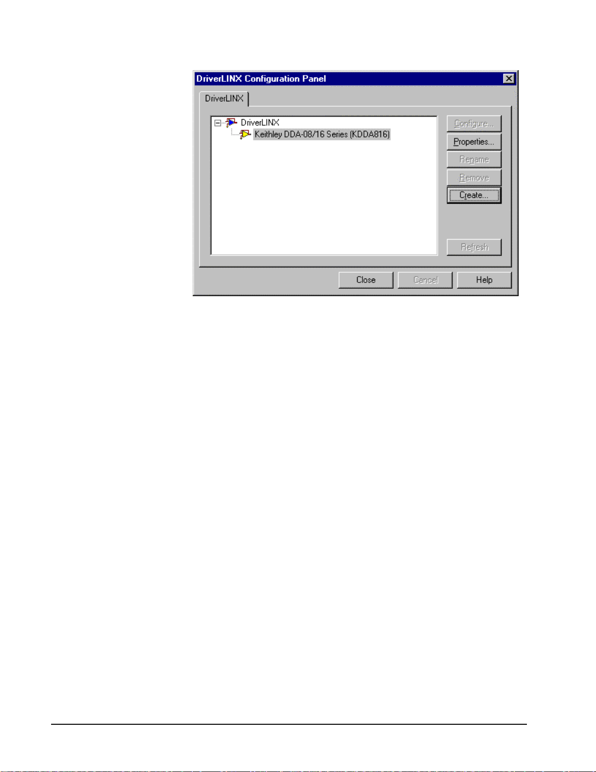
When you click the Configure… button on the DriverLINX Configuration Panel,
DriverLINX displays the Configure DriverLINX Device dialog. The dialog has a
page for each subsystem on a Keithley DDA-08/16 model. The following sections
describe your choices in configuring Dr iverLINX to work with your board.
12 • Configuring the DDA-08/16 Using DriverLINX With Your Hardware
Page 13
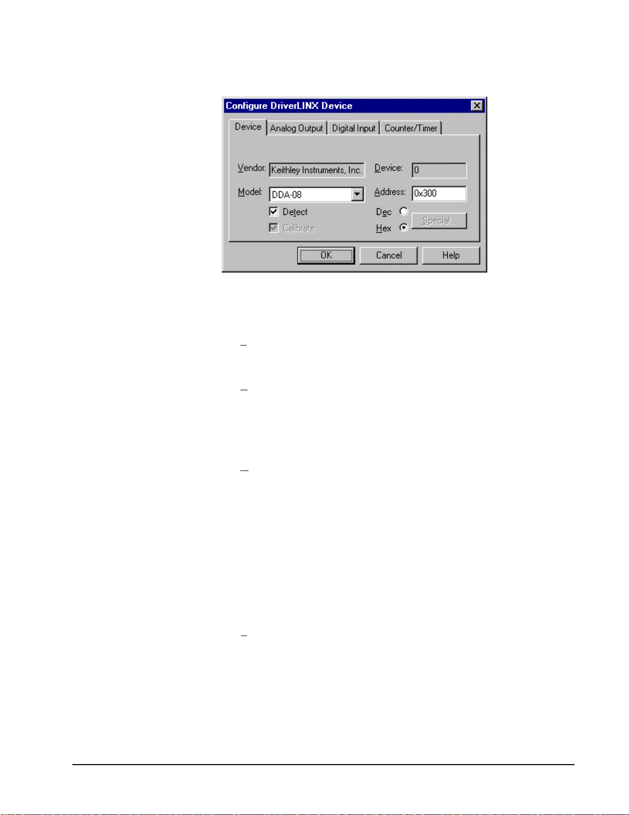
Device Subsystem Page
Use the Device Subsystem page to tell DriverLINX the model name and address of
your DDA-08/16 board.
Vendor
The Vendor property displays “Keithley Instruments, Inc.” It is a read-only property.
Device
Windows NT
Windows 95/98
Windows NT
The Device property designates the Logical Device you are configuring. It is a readonly property. To change it, first save (OK) or quit (Cancel) the current
configuration. Then select or create a new Logical Device using the DriverLINX
Configuration Panel.
Model
The Model property selects or indicates the hardware model of the board you’re
configuring.
Select one of the following models:
DDA-08
DDA-16
Under Windows 95/98, DriverLINX displays the model you chose during
installation. To install a different model, cancel the configuration and run Add New
Hardware from the Windows Control Panel.
Address
The Address property records the I/O port address for the board. The default address
used by DriverLINX is 768 decimal or 0x300 hex. If you have another peripheral
board at that address, select a different base address. Note: you need a block of eight
free addresses for a DDA-08/16 board.
Windows 95/98
Using DriverLINX With Your Hardware Configuring the DDA-08/16 • 13
Under Windows 95/98, Add New Hard ware automatically selects an appropriate
address. To change the address, see “Using the Windows 95/98 Device Manager” on
page 14.
Page 14
Detect
The Detect property enables and disables DriverLINX’s hardware detection and
testing algorithms. For maximum system reliability, always leave this check-box
marked.
Calibrate
The Calibrate property enables and disables hardware auto-calibration. This option is
grayed-out for the DDA-08/16 because it does not support automatic calibration.
Special…
The Special… button displays a dialog for configuring any special, hardware-specific
settings. For the DDA-08/16, Logical Device c onfiguration does not r equire any
special settings so DriverLINX disables the Special… button.
Using the Windows 95/98 Device Manager
Under Windows 95/98, DriverLINX uses the address and interrupt settings
maintained by the Windows Device Manager.
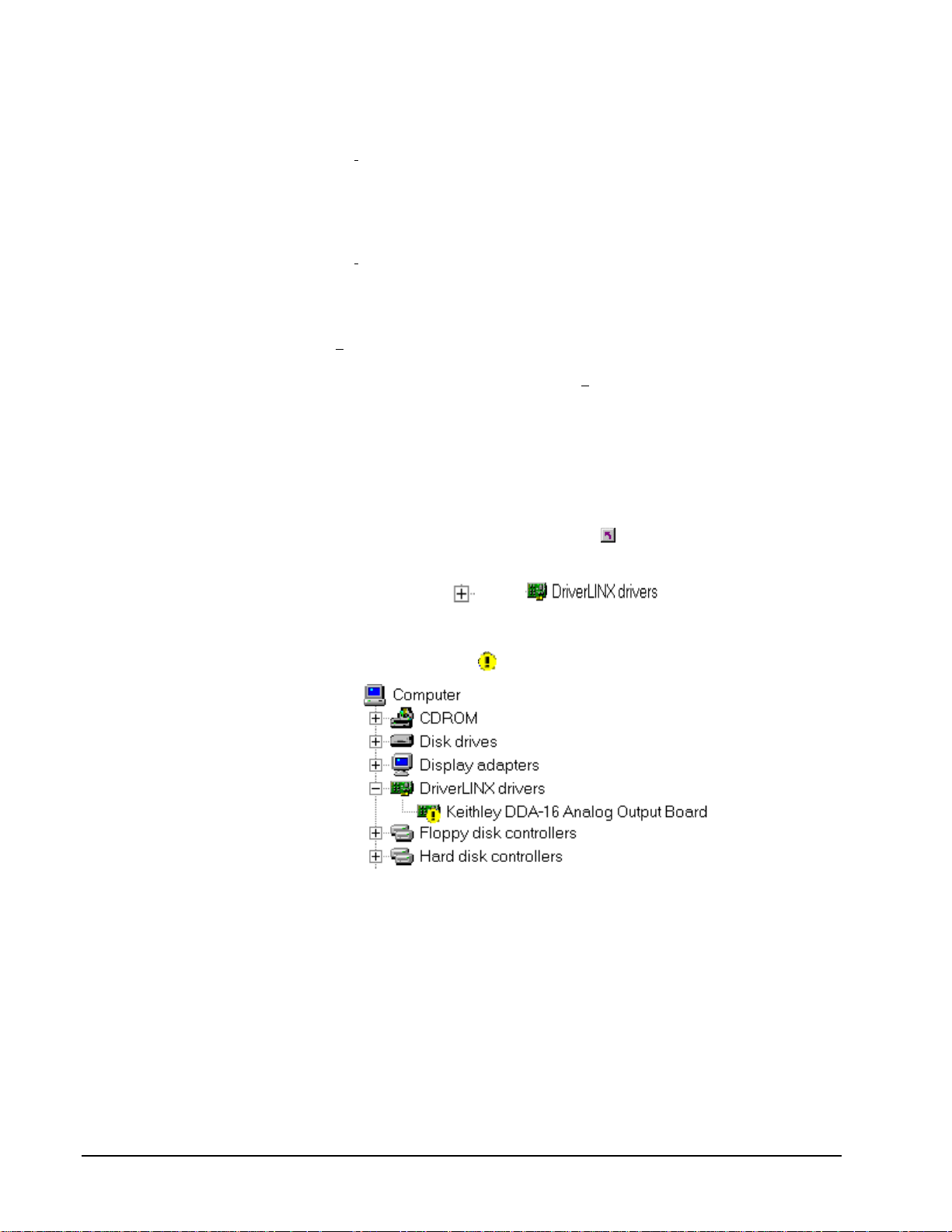
To view or change the settings for your board using the Device Manager:
1. Start the Device Manger by right-clicking on My Computer and
selecting Properties or click here
2. Click the Device Manger tab.
.
3. Click the
list.
4. Under DriverLINX drivers, select the entry for your board. (It may or
may not have
5. Click the Properties button.
6. On the board’s property page, click the Resources tab.
7. To configure the board with an interrupt, use Setting based on “Basic
configuration 0.” Or, to configure the board without an interrupt, use
Setting based on “Basic configuration 1. ”
8. To change a setting, select it under Resource Type and click the Change
Setting button. Windows will guide you in selecting an appropriate
value.
next to , if necessary to expand the
next to it.)
9. When you are done, click OK to close the board’s property page.
14 • Configuring the DDA-08/16 Using DriverLINX With Your Hardware
Page 15

10. The board’s address switches must match the address setting you select.
If necessary shut down your computer and reposition them as described
in your hardware manual.
11. Restart Windows to load the Logical Device for your board using the
new settings.
Using DriverLINX With Your Hardware Configuring the DDA-08/16 • 15
Page 16

Analog Output Subsystem Page
Use the Analog Output Subsystem page to change the default D/A initialization
voltage or current values.
Channels
The Channels property allows you to select a Logical Channel for individual
configuration of its initialization voltage or current value.
Range
Windows NT
Windows 95/98
The DDA-08/16 boards allow output range selections for each channel. DriverLINX
automatically determines the channel's range from the board’s switch settings.
Interrupt
For Windows NT, select a free interrupt request level to support interrupt mode
transfers. Valid IRQ levels are: 3, 5, 7, 10, 11, 15 and None.
Under Windows 95/98, Add New Hard ware automatically selects an appropriate
interrupt. To change the address, see “Using the Windows 95/98 Device Manager”
on page 14.
DMA level
The DDA-08/16 does not use system DMA channels. DriverLINX disables this
property.
Volts
The Volts property allows you to specify an output voltage or current (in mA) for
each channel that DriverLINX uses when it initializes the hardware. DriverLINX’s
default initialization value is zero. DriverLINX ignores this property unless you also
check the Initialize property.
Initialize
Checking the Initialize check box instructs DriverLINX to use the Volts property,
rather than the default value, for analog output initialization. The hardware initializes
all analog outputs to 0 V or 4 mA upon power up.
16 • Configuring the DDA-08/16 Using DriverLINX With Your Hardware
Page 17

Calibrate
The Calibrate property enables and disables hardware auto-calibration. DriverLINX
disables this property as the DDA-08/16 DACs don’t support auto-calibration.
Using DriverLINX With Your Hardware Configuring the DDA-08/16 • 17
Page 18

Digital Input Subsystem Page
Channels
DriverLINX defines the following Logical Channels for the DDA-08/16 digital
inputs:
Logical Channel DriverLINX Function DDA-08/16 External
Connector
0 External Trigger TRIGGER IN
1 External Clock CLOCK IN
The Channels proper t y allows you to select a Logical Channel for c onfiguration or
viewing the channel’s range. The digital input channels on the DDA-08/16 boards
have a fixed configuration.
Range
The Range property specifies the supported digital input range for the selected
Logical Channel. This is a read-only property.
Interrupt
The DDA-08/16 uses the same interrupt for digital input as for analog output. Go to
the Analog Output page to set it. DriverLINX disables this property and displays it as
blank.
DMA level
The DDA-08/16 does not use system DMA channels. DriverLINX disables this
property and displays it as blank.
Configuration
The digital input channels on the DDA-08/16 boards have a fixed configuration.
DriverLINX disable these Configuration properties.
18 • Configuring the DDA-08/16 Using DriverLINX With Your Hardware
Page 19

For the DDA-08/16, there are
no configurable options on
the Counter/Timer subsystem
page.
Counter/Timer Subsystem Page
Resolution
The Resolution property specifies the clock frequency of the master oscillator. All
models have a 1 MHz clock source for pacing output tasks.
Interrupt
The DDA-08/16 does not support interrupts from counter/timers. DriverLINX
disables this property and displays it as blank.
Using DriverLINX With Your Hardware Configuring the DDA-08/16 • 19
Page 20

Using the DDA-08/16 with
DriverLINX
Introduction
This chapter shows you how to set up and use DDA-08/16 hardware features with
DriverLINX. See the Analog I/O Programming Guide for an overview of
DriverLINX programming.
The descrip tions here use the Edit Service Request dialogs for language and API
independence. For the correct syntax with the language you’re using, please see the
DriverLINX Technical Reference Manuals. For DriverLINX examples in your
programming language, please see the source cod e examples in the subfolders of
your DriverLINX installation directory or on the original distribution media.
DriverLINX Hardware Model for DDA-08/16
DriverLINX provides a portable, hardware-independent API for data-acquisition
boards while still allowing applications to access unique or proprietary hardware
features of specific products. To achieve this goal, DriverLINX maps a hardwareindependent, or abstract, data-acquisition model onto DDA-08/16 hardware
capabilities.
The following sections describe how DriverLINX implements DDA-08/16 hardware
features as Subsystems, Modes, Operations, Events, Logical Channels, Buffers, and
Messages.
DriverLINX Subsystems
The DDA-08/16 supports four DriverLINX Logical Subsystems:
1. Device—refers to a DDA-08/16 model as a whole.
2. Analog Output—refers to the analog output channels, clocks, and
control signals.
3. Digital Input—refers to the 8-bit digital input/output port as well as 1-
bit digital input (TTL) control signals, such as CLOCK IN, etc.
20 • Using the DDA-08/16 with DriverLINX Using DriverLINX With Your Hardware
Page 21

4. Counter/Timer—refers to the internal clock channel for pacing
input/output tasks.
DriverLINX Modes
Applications use modes in Service Requests to advise DriverLINX on their preferred
hardware data-transfer technique. The DriverLINX modes fall into two general
classes:
•
Foreground or synchronous modes. The calling application doe sn’t
regain control until DriverLINX completes the Service Request.
DriverLINX supports this mode for simple, single-value I/O operations
or software housekeeping functions that DriverLINX can complete
without a significant delay.
•
Background or asynchronous modes. The calling application regains
control as soon as DriverLINX initiates the task. The calling application
must synchronize with the data-acquisition task using status polling or
DriverLINX’s messages (preferred). DriverLINX supports this mode
for buffered data-transfers or for commands that require a significant
time to complete.
DriverLINX supports three modes with the DDA-08/16 for its commands (Service
Requests).
•
Polled Mode—This is a foreground or synchronous operation.
DriverLINX supports this mode for simple, single-value I/O operations
that the data-acquisition board can complete without significant delay.
•
Interrupt Mode—T his is a background or asynchronous operation.
DriverLINX transfers data between the computer’s memory and the
data-acquisition board using hardware interrupts and programmed I/O
transfers.
•
Other Mode—This is a fo reground or synchrono us operation.
DriverLINX supports this mode for initialization, configuration,
calibration, data conversion, and timebase operations.
The following table summarizes the data acquisition modes that DriverLINX
supports for each subsystem with the Keithley DDA-08/16.
Subsystem Polled Interrupt DMA Other
Analog Input
Analog Output
Digital Input
Digital Output
Counter/Timer
Device
√√ √
√
√√
√
DDA-08/16 Supported DriverLINX Modes.
Using DriverLINX With Your Hardware Using the DDA-08/16 with DriverLINX • 21
Page 22

DriverLINX Operations and Events
Applications construct DriverLINX data-acquisition tasks by combining a small
number of DriverLINX operations and events in many possible ways. The following
table summarizes the operations and events that DriverLINX supports for the
Keithley DDA-08/16. Later sections for each DriverLINX subsystem will describe
the operations and events in more detail.
Note: All subsystems allow the MESSAGE operation and the Analog Output
Subsystem allows the CONVERT operation, which are not shown in the table.
DriverLINX allows any Mode setting for these operations.
Subsystem Operation Events
Mode Timing Start Stop
Analog Input
Analog Output
Polled Start null null, cmd null, TC
Interrupt Start, Stop, Status dig, rate cmd, dig cmd, TC
Other Initialize
Digital Input
Other Initialize
Digital Output
Counter/Timer
Polled Start, Stop, Status null, rate,
CTSetup
Interrupt
Other Initialize,
Configure
Device
Other Initialize,
Configure,
Capabilities
null, cmd null, TC
Allowed Operations and Events for DDA-08/16 Subsystems and Modes.
22 • Using the DDA-08/16 with DriverLINX Using DriverLINX With Your Hardware
Page 23

The following list explains the Event abbreviations in the preceding table:
•
null—Null or None Event when a Service Request doesn’t require an
event
•
cmd—Command Event when DriverLINX starts or stops a task on
software command
•
TC—Terminal Count Event when DriverLINX processes all data
buffers once
•
rate—Rate Event specifies how DriverLINX paces or clocks data
transfer
•
dig—Digital Event specifies a trigger, clock, or other control signal to
pace, start, or stop a task
Logical Channels
DriverLINX designates the individually addressable hardware channels for each
subsystem as “Logical Channels.” Generally, the zero-based Logical Channel
numbering sequence closely follows the hardware manufacturer’s channel numbering
scheme.
In some cases, however, DriverLINX assigns Logic al Channel numbers to hard ware
features that users don’t commonly think of as “channels.” For instance, DriverLINX
commonly models external hardware clock input lines, external hardware trigger
input lines, and external interrupt inputs as 1-bit digital Logical Channels. In other
cases, DriverLINX models subsystem-specific features, such as internal pacer clocks,
as members of a more general purpose set of counter/timer channels.
For a list of DriverLINX assigned Logical Channel numbers, see the notes on each
supported subsystem.
Buffers
Applications usually use data buffers to exchange data between the application and
the data-acquisition hardware. When using data buffers, please note the following
points about DriverLINX’s data buffers:
•
DriverLINX supports data-acquisition tasks with 1 to 255 data buffers
per task.
•
DriverLINX imposes no size limits on a single buffer, although the
operating system or some hardware products may have size restrictions.
•
User applications must allow DriverLINX to allocate all data buffers to
guarantee application portability to different hardware and operating
systems and to insure that the hardware can physically access the buffer
memory.
• User applications usually don’t have concurrent or immediate access to
the in-use data buffer while DriverLINX is executing a data-acquisition
task.
Using DriverLINX With Your Hardware Using the DDA-08/16 with DriverLINX • 23
Page 24

Connecting Signals to the DDA-08/16
The Keithley hardware manual describes the data and control signals for the DDA08/16 and the connector pinouts for these signals. This section summarizes how
DriverLINX numbers the I/O data signals and how DriverLINX uses several of these
control connections for external clock and trigger inputs.
Analog Output Subsystem Signals
Keithley’s DDA-08/16 has eight or sixteen 12-bit analog output DACs. DriverLINX
maps these signals to Logical Channels as shown in the following table:
Number of D/A
Channels
8 D/A 0 OUT, GND – D/A 7 OUT, GND 0 - 7
16 D/A 0 OUT, GND – D/A 15 OUT, GND 0 - 15
How DriverLINX maps analog output hardware channels to Logical Channels.
The Analog Output Subsystem has an internal pacer clock, which DriverLINX
designates as Logical Channel 0 of the Counter/Timer subsystem.
Connector Name Logical
Channels
Digital Input Subsystem Signals
The Digital Input Subsystem has a trigger and an external clock which DriverLINX
models as 1-bit logical digital input ports. DriverLINX maps these signals to Logical
Channels as shown in the following table:
Port Connector Name Logical Channels
External trigger alias TRIGGER IN 0
External clock alias CLOCK IN 1
How DriverLINX maps digital input hardware channels to Logical Channels.
24 • Using the DDA-08/16 with DriverLINX Using DriverLINX With Your Hardware
Page 25

Counter/Timer Subsystem Signals
The Counter/Timer subsystem has a single 8-bit internal hardware timer to pace tasks
on the analog output subsystem. The DDA-08/16 also has an output clock, which
provides a delayed pulse each time the board updates a D/A channel. DriverLINX
maps the timers to Logical Channels as shown in the following table:
Timer Connector Name Logical Channels
Pacer Clock GATE IN, CLOCK IN,
Output Clock CLOCK OUT 1
How DriverLINX maps counter/timer hardware channels to Logical Channels.
Applications can operate these timers in tandem to generate a frequency output while
the analog output subsystem is idle.
Device Subsystem
The following sections describe how DriverLINX implements Device Subsystem
features for the DDA-08/16.
0
TRIGGER IN
If another application is using
the same data-acquisition
board, DriverLINX will
prevent Device Initialization
from interfering with the
other application’s dataacquisition tasks.
Device Modes
The Device Subsystem only supports DriverLINX’s Other mode for all operations.
Device Operations
The DDA-08/16 Device Subsystem supports the following DriverLINX operations:
•
Initialize—DriverLINX aborts all data-acquisition tasks for every
subsystem controlled by the current application. DriverLINX then
performs an initialization for each supported subsystem.
•
Configure—DriverLINX displays the Configure DriverLINX Device
dialog for the current Logical Device. Please use the DriverLINX
Configuration Panel rather than this operation to configure
DriverLINX.
•
Capabilities—DriverLINX provides hardware-specific and
configuration information in the form of a Logical Device Descriptor
database.
Using DriverLINX With Your Hardware Using the DDA-08/16 with DriverLINX • 25
Page 26

Analog Output Subsystem
The following sections describe how DriverLINX implements Analog Output
Subsystem features for the DDA-08/16.
Analog Output Modes
The Analog Output Subsystem supports the following modes:
•
Polled—For single-value analog output samples.
•
Interrupt—For buffered transfers using programmed I/O.
•
Other—For subsystem initialization and data conversion.
Analog Output Operations
The DDA-08/16 Analog Output Subsystem supports the following DriverLINX
operations:
•
Initialize—aborts all active analog output data-acquisition tasks.
However, DriverLINX prevents one application from interfering with
another application’s data-acquisition tasks.
•
Start—initiates a data-acquisition task using the Mode, Timing, Start,
and Stop Events, the Logical Channels, and the Buffers the application
specified in the Service Request.
•
Status—reports the buffer position of the next sample that DriverLINX
will write into a buffer.
•
Stop—terminates an analog output data-acquisition task.
•
Message—DriverLINX displays a pop-up dialog box for the user
containing the text for the current DriverLINX error message.
Analog Output Initialization
By default, the Analog Output Subsystem loads zero into all D/A channels forcing
the initial output level to 0 V or 4 mA.
Analog Output Timing Events
Timing Events specify how the hardware paces or clocks the sample output.
DriverLINX uses the Timing Event to program when the DDA-08/16 writes the next
analog output sample to the DACs.
The DDA-08/16 supports the following Timing Events:
• None—Output requires no pacing as DriverLINX is writing only a
single value.
• Rate—The DDA-08/16 supports only fixed rate analog output using
internal and external clocks.
• Digital—DriverLINX uses an external digital input signal to pace the
output of each sample.
26 • Using the DDA-08/16 with DriverLINX Using DriverLINX With Your Hardware
Page 27

None or Null Event
The Null Event specifies that the task does not need a clock to determine when to
write the next sample.
Rate Event
The DDA-08/16 supports one type of Rate Event for analog output:
•
Rate Generator—Generates a fixed rate clock with equal time
intervals between tics.
Rate Generator: Internal Clocking
An internally clocked Rate Generator produces a fixed rate clock with equal time
intervals between tics.
Period
Use an internally clocked rate generator when you want to write analog output
samples at equally spaced time intervals. Note, the DDA-08/16 hardware can write
the selected analog output channels simultaneously at each timing event, or
individually, with one channel per timing event.
How to set up the DDA-08/16 for fixed rate sampling using an internal clock.
Using DriverLINX With Your Hardware Using the DDA-08/16 with DriverLINX • 27
Page 28

For hardware independence,
specify the clock channel
using the symbolic constant,
DEFAULTTIMER, which
always maps to the default
Logical Channel for analog
output timing.
•
Specify internal clocking using a Rate Generator on Channel 0 with
an Internal 1 Clock source.
•
The Period property specifies the time interval between samples in tics,
where a tic is 1 µs, or 1 MHz. The minimum period is 20 tics, or 50
kHz. The maximum period is 25500 tics, or 0.004 Hz. See
“Counter/Timer Subsystem” on page 38 for details on the counter/timer
channels.
•
The Gate property specifies how the GATE IN signal affects sampling.
See “Counter/Timer Subsystem” on page 38 for details on the gate
modes.
Rate Generator: External Clocking
An externally clocked Rate Generator produces a rate clock with unknown time
intervals between tics.
Period (ext clk)
Use an externally clocked rate generator when you want to synchronize analog output
samples with a recurrent external signal. Note, the DDA-08/16 hardware can write
the selected analog output channels simultaneously at each timing event, or
individually, with one channel per timing event.
How to set up the DDA-08/16 for fixed rate sampling using an external clock.
BE SURE that the external
clock source is TTL
compatible, 0 V minimum to
+5 V maximum!
28 • Using the DDA-08/16 with DriverLINX Using DriverLINX With Your Hardware
• Specify external clocking using a Rate Generator on Channel 0 with
an External, External+ or External- Clock source. External and
External+ both specify sampling on the rising, or positive, edge of the
external clock signal.
• Users should connect the external clock signal to the CLOCK IN line.
Page 29

•
The Period may be any va lue ≥ 1 tic, or 1 µs. The period value doesn’t
affect the external clock frequency, but DriverLINX requires a valid
hardware value in case the application requests a timebase operation
and to optimize data transfer between the driver and the application.
•
The Gate property specifies how the GATE IN signal affects sampling.
See “Counter/Timer Subsystem” on page 38 for details on the gate
modes.
Digital Event
DriverLINX supports Digital Events as aliases for externally clocked Rate
Generators. Use this technique for compatibility with data-acquisition boards that
only support external clock sources. Note, the DDA-08/16 hardware can write the
selected analog output channels simultaneously at each timing, or individually, with
one channel per timing event.
How to set up the DDA-08/16 for external rate sampling using a digital event.
Digital Timing Events contain mask, pattern, and match fields. The mask is logically
ANDed with the digital input data on the Logical Channel and then compared against
the pattern for a match/mismatch.
BE SURE that the external
clock source is TTL
compatible, 0 V minimum to
+5 V maximum!
Using DriverLINX With Your Hardware Using the DDA-08/16 with DriverLINX • 29
•
Specify external clocking using Channel 1. For hardware-
independence, you can specify the hardware external trigger channel by
the symbolic constant, DI_EXTCLK.
• Users should connect the external clock signal to the CLOCK IN line.
• Specify the Mask property as 1, or Bit 0, to indicate that DriverLINX
should only compare a 1-bit digital input value against the Pattern
property.
• Specify the Match property as Not equals.
• Specify the Pattern property as 0 for a rising, or positive, edge clock
(≠1), or 1 for a falling, o r negative, edge clock (≠0).
Page 30

Analog Output Start Events
Start Events specify when the DDA-08/16 hardware starts writing analog output data.
The DDA-08/16 supports the following Start Events for analog output:
•
None—Use this event when the DriverLINX operation does not require
a Start Event.
•
Command—DriverLINX starts the task on software command, i.e., as
soon as DriverLINX finishes programming the DDA-08/16 hardware
for the task.
•
Digital—The DDA-08/16 starts writing analog output samples when
the hardware detects that the digital input satisfies the condition
specified in the Start Event.
None or Null Event
The Null Event specifies that the task does not need a Start Event to begin the task.
Command Event
The Command Event starts data acquisition as soon as DriverLINX has completed
programming the data-acquisition hardware with the task parameters.
Digital Event or Post-Triggering
The DDA-08/16 can write analog output samples after the hardware detects a digital
trigger condition. Use post-triggering when you want to synchronize the start of data
acquisition with an external signal.
How to set up the DDA-08/16 for post-triggered analog output.
Digital Start Events contain mask, pattern, and match fields. The mask is logically
ANDed with the digital input data on the Logical Channel and then compared with
the pattern for a match/mismatch.
30 • Using the DDA-08/16 with DriverLINX Using DriverLINX With Your Hardware
Page 31

•
Specify the Channel as 0. For hardware-independence, you can specify
the hardware external trigger channel by the symbolic constant,
DI_EXTTRG.
•
Specify the Mask and Pattern properties to 1 to specify the bit position
of the 1-bit trigger input.
•
Specify the Match property as Not equals to trigger on the edge of the
trigger input.
•
Specify the Delay property as any number of samples from 0 to
•
Connect the signal to the TRIGGER IN line.
Analog Output Stop Events
Stop Events specify when the hardware stops writing analog output data.
The DDA-08/16 supports the following Stop Events for analog output:
•
None—Use this event when the DriverLINX operation doesn’t require
a Stop Event.
•
Command—DriverLINX stops the task on software command, i.e.,
when the application issues a Service Request with a Stop operation.
•
Terminal count—DriverLINX stops the task after the data-acquisition
hardware has written all the data buffers once.
32
21
− .
None or Null Event
The Null Event specifies that the task does not need a Stop Event to end the task.
Command Event
The Command Event stops data acquisition when the user application changes the
Operation property in the Service Request to Stop and resubmits the Service Request
to DriverLINX.
In Stop-on-Command mode, DriverLINX continuously cycles through all the data
buffers, writing them to the DACs on the DDA-08/16.
Terminal Count Event
The Terminal Count Event stops data acquisition after DriverLINX has written the
analog output data in all the data buffers once. Use Terminal Count when you want to
write a fixed amount of data.
Using DriverLINX With Your Hardware Using the DDA-08/16 with DriverLINX • 31
Page 32

Analog Output Channels
The DDA-08/16 allows applications to specify the analog channels using three
techniques:
•
Start Channel—Write analog data to a single channel.
•
Start/Stop Channel Range—Write analog data to a consecutive range
of channels.
•
Channel List—Write analog data to a list of channels.
The DDA-08/16 boards have individual gain switches for each channel. DriverLINX
uses a gain code of zero for all switch settings. Consequently, the Gain2Code
function always returns zero.
Analog Output Logical Channels
The DDA-08/16 has eight or sixteen 12-bit digital-to-analog converter channels.
DriverLINX maps these physical channels to Logical Channels as follows:
Number of D/A
Channels
8 D/A 0 OUT, GND – D/A 7 OUT, GND 0 - 7
16 D/A 0 OUT, GND – D/A 15 OUT, GND 0 - 15
Connector Name Logical
Channels
Single Channel Analog Output
In single channel mode, the DDA-08/16 writes all data to one channel.
How to set up the DDA-08/16 to write to a single DAC Channel.
32 • Using the DDA-08/16 with DriverLINX Using DriverLINX With Your Hardware
Page 33

Multi-channel Analog Output Range
In multi-channel range mode, the DDA-08/16 writes all data to a consecutive range
of analog channels.
•
If the Start Channel is greater than the Stop Channel, the channel
sequence is [Start Channel,…, Last Channel, 0, …, Stop Channel],
where Last Channel is the highest numbered channel for the DDA08/16 model the application is using.
•
The DDA-08/16 can optionally output to all DACs in the range
simultaneously, or write to one DAC in the range at each timing event.
How to set up the DDA-08/16 using a start/stop range to write to multiple DACs.
Multi-channel Analog Output List
In multi-channel list mode, the DDA-08/16 acquires all data to a random list of
analog channels.
•
The channel-gain list may contain channels in any order but only with
unity gain. In simultaneous mode, the list may not repeat the same
channel.
•
The DDA-08/16 can optionally output to all DACs in the list
simultaneously, or write to one DAC in the list at each timing event.
Using DriverLINX With Your Hardware Using the DDA-08/16 with DriverLINX • 33
Page 34

How to set up the DDA-08/16 using a channel list to write to multiple DACs.
Analog Output Buffers
DriverLINX supports both single-value analog output and buffered analog output.
•
For single-value output, specify the Number of buffers as 0 and the
number of Samples as 1. Use Polled mode and store the data in the
ioValue Service Request property.
•
For buffered output, specify the Number of buffers from 1 to 256 and
the number of Samples as desired.
34 • Using the DDA-08/16 with DriverLINX Using DriverLINX With Your Hardware
Page 35

How to set up the DDA-08/16 for analog output using buffers.
For example, 500 samples/2
channels = 250 is ok, but 500
samples/3 channels = 166.67
is incorrect.
An individual DriverLINX buffer may have any size as long as the buffer length
holds an integral number of channel scans (i.e., a multiple of the number of analog
output channels you are using). This restriction enforces the requirement that all
channels have the same number of samples.
Analog Output Data Coding
The DDA-08/16 offers both a bipolar and unipolar analog output ranges. Bipolar
ranges encode D/A output values using a 12-bit binary offset integer. Unipolar ranges
encode D/A output va lues using a 12-bit true binary (unsigned) integer. Driver LINX
refers to these coding schemes as the “native” format for the channel data.
D/A Resolution Range A/D Hardware
Code
12 bits ±2.5 V 0 - 4095
12 bits ±5 V 0 - 4095
12 bits ±10 V 0 - 4095
12 bits 4 –20 mA 0 - 4095
12 bits 0 –5 V 0 - 4095
12 bits 0 - 10 V 0 - 4095
Native hardware codes for the DDA-08/16 DACs.
10
8
6
4
2
0
0 4095
-2
-4
-6
DDA-08/16 native D/A Codes versus Voltage for the 0-10V and ±5V Ranges.
Unipolar
Bipolar
DriverLINX refers to the default hardware analog coding scheme as the “native”
format. For computer a rithmetic in a higher level language, the integer, or two’s
complement, format is generally easier to use. For unipolar data, native and integer
formats are identical.
For bipolar data, DriverLINX automatically converts A/D codes to integer format, if
you specify integer for the Format property. Or, applications can use DriverLINX’s
data conversion operations to transform an entire data buffer from native format to
many common integer and floating-point formats.
Because the DDA-08/16 boards have gain switches for each channel, applications
should use buffer conve rsions instead of the single-value functions, Volts2Code and
Code2Volts.
Using DriverLINX With Your Hardware Using the DDA-08/16 with DriverLINX • 35
Page 36

Analog Output Messages
For analog output operations, DriverLINX can report the following messages to the
application:
DriverLINX Message Explanation
Service Start DriverLINX has started the acqu i sition task.
Service Done DriverLINX has completed the acquisition task.
Buffer Filled DriverLINX has finished writing from the data buffer.
Start Event DriverLINX has processed the interrupt for a hardware start
event
Stop Event DriverLINX has processed the interrupt for a hardware stop
event
Data Lost DriverLINX has detected an analog output data underrun
condition.
Critical Error DriverLINX has encountered an unexpected hardware or
software condition.
DriverLINX Event messages for analog output.
36 • Using the DDA-08/16 with DriverLINX Using DriverLINX With Your Hardware
Page 37

Digital Input Subsystem
The following sections describe how DriverLINX implements Digital Input
Subsystem features for the DDA-08/16.
Digital Input Modes
The Digital Input Subsystem supports the following mode:
•
Other—For subsystem initialization.
Digital Input Operations
The DDA-08/16 Digital Input Subsystem supports the following DriverLINX
operations:
•
Initialize—aborts any active interrupt data-acquisition tasks and stops
•
Message—DriverLINX displays a pop-up dialog box for the user
Digital Port Configuration
The DDA-08/16 has only two fixed-configuration input signals. Therefore,
DriverLINX does not allow the application to configure the DDA-08/16’s Digital
Input Subsystem channels.
the clock. However, DriverLINX prevents one application from
interfering with another application’s data-acquisition tasks.
containing the text for the current DriverLINX error message.
Digital Input Timing Events
Timing Events specify how the hardware paces or clocks the reading of Digital Input
samples. Because the DDA-08/16 does not have any digital input data channels,
DriverLINX does not allow application to create any independent tasks with the
Digital Input Subsystem.
Digital Input Channels
The DDA-08/16 has only two input signals that DriverLINX assigns to the Digital
Input Subsystem: TRIGGER IN and CLOCK IN. Application can use these external
clock and trigger signals to control analog output or co unter/timer tasks but
applications cannot directly read their values.
Logical Channel DriverLINX Function DDA-08/16 External
Connector
0 External Trigger TRIGGER IN
1 External Clock CLOCK IN
Using DriverLINX With Your Hardware Using the DDA-08/16 with DriverLINX • 37
Page 38

Counter/Timer Subsystem
The DDA-08/16 has a simple counter/timer subsystem. It allows analog output
pacing at rates from 0.004 Hz to 50 kHz. In addition, it can perform independent
counter/timer tasks while the analog output subsystem is idle, such as frequency
division and strobe generation.
The following table lists the Counter/Timer Subsystem’s Logical Channels and shows
their allowable clock sources, modes and gates.
Logic a l Channels Modes Gates
0 — P acer Clock Internal 1 1 µs (1 M Hz) Rate Gen Enabl ed
Internal 2 10 µs (100 kHz) Freq Divider Disabled
Internal 3 100 µs (10 k Hz ) No Connect
Internal 4 1 ms (1 k Hz ) Low Level
Internal 5 10 ms (100 Hz ) High Level
Source 1 100 ms (10 Hz)
Source 2 1 s (1 Hz)
External
External+
External
1 — Output Clock Internal 1 1 µs (1 MHz ) Ret ri g One -S hot Enabled
Internal 2 10 µs (100 kHz) No Connect
Internal 3 100 µs (10 kHz)
Internal 4 1 ms (1 kHz)
Internal 5 10 ms (100 Hz )
Source 1 100 ms (10 Hz)
Source 2 1 s (1 Hz)
External
External+
External
Source Tic Period
Clocks
Counter/Timer Subsystem Logical Channels and Allowed Clocks, Modes and Gates.
Pacer Clock
The Pacer Clock (Logical Channel 0) is an 8-bit counter combined with a 7-range
prescaler that supports both internal and external clock sources.
Internal Clocking
The DDA-08/16 has a master oscillator with seven prescaler outputs to pace
input/output tasks. DriverLINX defines the following internal clock sources for the
Pacer Clock:
•
Internal 1—specifies a clock source that allows the full range of
output frequencies, from 0.004 Hz to 1 MHz. With this clock source
each tic is 1 µs.
• Internal 2—specifies the 100 kHz clock source, which allows output
frequencies from 393 Hz to 100 kHz. With this clock source each tic is
10 µs.
• Internal 3—specifies the 10 kHz clock source, which allows output
frequencies from 40 Hz to 10 kHz. With this clock source each tic is
100 µs.
• Internal 4—specifies the 1 kHz clock source, which allows output
frequencies from 4 Hz to 1 kHz. With this clock source each tic is 1 ms.
38 • Using the DDA-08/16 with DriverLINX Using DriverLINX With Your Hardware
Page 39

•
Internal 5—specifies the 100 Hz clock source, which allows output
frequencies from 0.4 Hz to 100 Hz. With this clock source each tic is
10 ms.
•
Source 1—specifies the 10 Hz clock source, which allows output
frequencies from 0.04 Hz to 10 Hz. With this clock source each tic is
100 ms.
•
Source 2—specifies the 1 Hz clock source, which allows output
frequencies from 0.004 Hz to 1 Hz. With this clock source each tic is
1 s.
Applications that wish to control the prescaler selection should choose a clock source
from Internal 1 through Source 2 to specify a specific prescaler and use a tic count
from 1 to 256.
External Clocking
The DDA-08/16 allows an external clock source to pace input/output tasks.
DriverLINX defines the following external clock sources for the Pacer Clock:
•
External, External+ —specify sampling on the rising, or positive,
edge of the external clock signal.
•
External- —specifies sampling on the falling, or negative, edge of the
external clock signal.
Clocking Modes
The Pacer Clock can operate in either of two modes. DriverLINX defines the
following clock modes for this Logical Channel:
•
Rate Generator—specifies sampling of one channel (or all channels
simultaneously) in the scan list at each tic of an internal or external
clock source.
•
Frequency Divider—provides a waveform output at the input
frequency divided by a specified value. The Pacer Clock must have an
internal clock source in this mode.
Gating
The Pacer Clock has a level-active gate input, GATE IN, that enables and disables its
operation. The gate control has the following modes:
•
Enabled—specifies that the application needs the gate enabled. A
signal at the gate connection enables or disables the counter/timer with
a default active state. For the DDA-08/16, DriverLINX uses High Level
for the active state.
• Disabled—specifies that the application needs the gate disabled. Any
signal present at the connection does not affect the counter/timer.
• No Connect—specifies that the application does not need a gate
input. For the DDA-08/16, DriverLINX disables the gate for this mode.
• High Level—specifies that the application needs the gate enabled with
a High Level active state. A signal at the gate connection enables the
counter/timer when it is high and disables the counter/timer when it is
low.
• Low Level—specifies that the application needs the gate enabled with
a Low Level active state. A signal at the gate connection enables the
Using DriverLINX With Your Hardware Using the DDA-08/16 with DriverLINX • 39
Page 40

counter/timer when it is low and disables the counter/timer when it is
high.
Output Clock
The Output Clock (Logical Channel 1) is an 8-bit counter combined with a 7-range
prescaler that supports both internal and external clock sources.
Internal Clocking
The DDA-08/16 has a master oscillator with seven prescaler outputs to pace
input/output tasks. DriverLINX defines the following internal clock sources for the
Output Clock:
•
Internal 1—specifies a clock source that allows the full range of
output frequencies, from 0.004 Hz to 1 MHz. With this clock source
each tic is 1 µs.
•
Internal 2—specifies the 100 kHz clock source, which allows output
frequencies from 393 Hz to 100 kHz. With this clock source each tic is
10 µs.
•
Internal 3—specifies the 10 kHz clock source, which allows output
frequencies from 40 Hz to 10 kHz. With this clock source each tic is
100 µs.
•
Internal 4—specifies the 1 kHz clock source, which allows output
frequencies from 4 Hz to 1 kHz. With this clock source each tic is 1 ms.
•
Internal 5—specifies the 100 Hz clock source, which allows output
frequencies from 0.4 Hz to 100 Hz. With this clock source each tic is
10 ms.
•
Source 1—specifies the 10 Hz clock source, which allows output
frequencies from 0.04 Hz to 10 Hz. With this clock source each tic is
100 ms.
•
Source 2—specifies the 1 Hz clock source, which allows output
frequencies from 0.004 Hz to 1 Hz. With this clock source each tic is
1 s.
Applications that wish to control the prescaler selection should choose a clock source
from Internal 1 through Source 2 to specify a specific prescaler and use a tic count
from 1 to 256.
External Clocking
The DDA-08/16 allows an external clock source for Output Clock tasks. DriverLINX
defines the following external clock sources for the Output Clock:
• External, External+ —specify counting on the rising, or positive,
edge of the external clock signal.
• External- —specifies counting on the falling, or negative, edge of the
external clock signal.
40 • Using the DDA-08/16 with DriverLINX Using DriverLINX With Your Hardware
Page 41

Clocking Modes
The Output Clock can operate in only one mode. DriverLINX defines the following
clock mode for this Logical Channel:
•
Retriggerable One-Shot—specifies a single pulse after detecting a
gate signal. The pulse starts after a delay period. A subsequent gate
signal triggers another pulse. For the DDA-08/16 the length of the pulse
is one-half the prescaler output period.
Gating
The Output Clock has an edge active gate input that triggers its operation. The gate
source is output of the Pacer Clock. It triggers the Output Clock at same time it
causes a DAC update. The DDA-08/16 does not allow any software control over the
gate. However, for compatibility with other boards, DriverLINX defines the
following gate control modes:
•
Enabled—specifies that the application needs the gate enabled. A
signal at the gate connection enables or disables the counter/timer with
a default active state. The DDA-08/16 always uses Low Edge for the
active state.
•
No Connect—specifies that the application does not need a gate
input. The DDA-08/16 always uses Low Edge for the active state.
•
Low Edge—specifies that the application needs the gate enabled with
a Low Level active state. A signal at the gate connection enables the
counter/timer when it is low and disables the counter/timer when it is
high. The DDA-08/16 always uses Low Edge for the active state.
Using DriverLINX With Your Hardware Using the DDA-08/16 with DriverLINX • 41
Page 42

Page 43

Glossary of Terms
A/D
Abbreviation for Analog-to-Digital, a process that converts a continuous analog
signal into a discrete digital approximation of the analog signal.
ADC
Abbreviation for Analog-to-Digital Converter, the hardware that performs the A/D
conversion.
API
Abbreviation for Application Programming Interface. An API defines the syntax of
the data structures and functions of software services.
Buffer
A block of memory used to receive data from a data-acquisition device or to write
data to a data-acquisition device.
Clocking
A periodic pulse or signal that data-acquisition hardware uses to read or write the
next sample or block of samples. Also referred to as “pacing”.
D/A
Abbreviation for digital-to-analog, a process that converts a discrete digital value into
a continuous analog voltage representing that value.
DAC
Abbreviation for digital-to-analog converter, the hardware that performs the D/A
conversion.
Using DriverLINX With Your Hardware Glossary of Terms • 43
Page 44

DMA
Abbreviation for Direct Memory Access, a technique where the system board can
transfer data between a device and memory without using the CPU. In the PC, a
standard chip on the system board controls the transfer.
Event
For DriverLINX, an event is the occurrence of a signal that clocks, starts, or stops a
data-acquisition task.
Gating
A signal that enables and disables another signal or data-acquisition task depending
on the value of the gate signal.
IRQ
Abbreviation for interrupt request. Peripheral hardware signals the CPU that it is
ready to transfer data.
ISA
Abbreviation for Industry Standard Architecture. A standard for the original IBM AT
bus specification that defines the bus structure, CPU and support chip architecture,
and the clock frequency of the ISA bus.
ISR
Abbreviation for interrupt service routine, the software function inside a device
driver that handles interrupt requests.
Logical Device
DriverLINX’s designation for a specific data-acquisition board inside your computer.
Messages
In Windows and DriverLINX, a message notifies the application about the state of a
process.
Modes
DriverLINX data-acquisition techniques.
Operations
Allowed DriverLINX data-acquisition commands.
44 • Glossary of Terms Using DriverLINX With Your Hardware
Page 45

Pacing
A periodic pulse or signal that data-acquisition hardware uses to read or write the
next sample or block of samples. Also referred to as “clocking”.
Process
Refers to the collection of data and code segments and hardware resources that the
operating system assigns to one application.
Service Request
A DriverLINX object or data structure that completely defines a data-acquisition
task.
Subsystem
DriverLINX subdivides a general-purpose data-acquisition device into six
subsystems—Device, Analog Input, Analog Output, Digital Input, Digital Output,
and Counter/Timer.
Triggering
The technique of using a pulse or signal to start or stop a d a ta-acquisition task.
TTL
Abbreviation for transistor-transistor logic, a family of digital logic elements.
Using DriverLINX With Your Hardware Glossary of Terms • 45
 Loading...