

Page 1

Keithley DAS-TC/B
Using DriverLINX with Your
Hardware
Page 2

Information in this document is subject to change without notice. The software
described is this document is furnished under a license agreement. The software may
be used or copied only in accordance with the terms of the agreement.
SCIENTIFIC SOFTWARE TOOLS, INC. SHALL NOT BE LIABLE FOR ANY
SPECIAL, INCIDENTAL, OR CONSEQUENTIAL DAMAGES RELATED TO
THE USE OF THIS PRODUCT. THIS PRODUCT IS NOT DESIGNED WITH
COMPONENTS OF A LEVEL OF RELIABILITY SUITABLE FOR USE IN LIFE
SUPPORT OR CRITICAL APPLICATIONS.
This document may not, in whole or in part, be copied, photocopied, reproduced,
translated or reduced to any electronic medium or machine readable form without
prior written consent from Scientific Software Tools, Inc.
Keithley DAS-TC/B: Using DriverLINX with Your Hardware
Copyright 1999 by Scientific Software Tools, Inc.
All rights reserved.
First Printing.
SST 22-0599-1
DriverLINX, SSTNET, and LabOBJX are registered trademarks and
DriverLINX/VB is a trademark of Scientific Software Tools, Inc.
MetraByte is a trademark of Keithley Instruments, Inc.
Microsoft and Windows are registered trademarks and Visual C++ and Visual Basic
are trademarks of Microsoft Corporation.
Borland is a registered trademark and Borland C++ and Delphi are trademarks of
Borland International, Inc.
All other brand and product names are trademarks or registered trademarks of their
respective companies.
2
Page 3

Contents
Preface 5
Software License and Software Disclaimer of Warranty............................................................5
About DriverLINX.....................................................................................................................7
About This User’s Guide...........................................................................................................7
Conventions Used in This Manual.............................................................................................9
Configuring the DAS-TC/B 11
Introduction..............................................................................................................................11
Configure DriverLINX Device Dialog.....................................................................................11
Using the DAS-TC/B with DriverLINX 19
Introduction..............................................................................................................................19
DriverLINX Hardware Model for DAS-TC/B.........................................................................19
Connecting Signals to the DAS-TC/B......................................................................................23
Device Subsystem....................................................................................................................24
Analog Input Subsystem ..........................................................................................................25
Counter/Timer Subsystem........................................................................................................43
Device Subsystem Page.............................................................................................13
Analog Input Subsystem Page ...................................................................................17
Counter/Timer Subsystem Page.................................................................................18
DriverLINX Subsystems............................................................................................19
DriverLINX Modes ...................................................................................................20
DriverLINX Operations and Events..........................................................................21
Logical Channels.......................................................................................................21
Buffers.......................................................................................................................22
Analog Input Subsystem Signals................................................................................23
Device Modes............................................................................................................24
Device Operations .....................................................................................................24
Analog Input Modes..................................................................................................25
Analog Input Operations............................................................................................25
Analog Input Timing Events......................................................................................26
Analog Input Start Events..........................................................................................31
Analog Input Stop Events..........................................................................................31
Analog Input Channels...............................................................................................33
Analog Input Buffers .................................................................................................40
Analog Input Data Coding.........................................................................................40
Analog Input Messages..............................................................................................42
Uninstalling DriverLINX 45
How do I uninstall DriverLINX? .............................................................................................45
Keithley DAS-TC/B Contents • 3
Page 4

Troubleshooting 47
Solving Problems.....................................................................................................................47
Solving Problems Installing Drivers..........................................................................47
Solving Problems Configuring the Drivers................................................................47
Solving Problems Loading Drivers............................................................................48
Generating a DriverLINX Configuration Report.....................................................................51
What is in the Report? ...............................................................................................51
How do I Generate the Report?.................................................................................51
Glossary of Terms 52
4 • Contents Keithley DAS-TC/B
Page 5

Preface
Software License and Software Disclaimer of Warranty
This is a legal document which is an agreement between you, the Licensee, and S cientific Software Tools, Inc. By opening this
sealed diskette pack age, Licensee agrees to become bound by t he terms of this Agreement , which include the Software License and
Software Disclaimer of Warranty.
This Agreement constitutes the c omplete Agreement between Licensee and Scientific S oftware Tools, Inc. If Licensee does not
agree to the terms of this Agreement, do not open the diskette pack age. Promptly return t he unopened diskette pac kage and the other
items (including writt en materials, binders or ot her containers, and hardware, if any ) that are part of this product to Sc ientific Software
Tools, Inc. for a full refund. No ref unds will be given for products that have opened disk packages or missing components.
Licensing Agreement
Copyright. The software and documentation is owned by Scientific Software Tools, Inc . and is protected by both United States
copyright laws and internati onal treaty provisions. Scientif ic Software Tools, Inc. authorizes the original purchaser only (Licensee) to
either (a) make one copy of the s oftware solely f or backup or archival purpos es, or (b) transfer t he software to a single hard disk only.
The written materials acc om panying the software may not be duplicated or copied for any reason.
Trade Secret. Licensee understands and agrees that t he software is the proprietary and conf idential property of Scienti fic Soft ware
Tools, Inc. and a valuable trade secret. Licensee agrees t o use the soft ware only for the int ended use under this Lic ense, and shall not
disclose the soft ware or i t s contents to any third part y.
Copy Restrictions. The Licensee may not modify or translate the program or relat ed documentation without the prior written
consent of Scientific Software Tools, Inc. All modifications, adaptat ions, and merged porti ons of the sof tware consti tute the s oftware
licensed to the Licensee, and the terms and condit ions of this agreem ent apply to sam e. Licensee may not distribute c opies, inc luding
electronic transfer of copies, of the m odified, adapt ed or merged sof tware or accom panying writt en material s to others . Licens ee agrees
not to reverse engineer, decompil e or di sassemble any part of the s of tware.
Unauthorized copying of the s oftware, incl uding software that has been modified, merged, or included wit h other software, or of the
written materials is expressly forbidden. Licensee may not rent, trans fer or lease the software to any t hird parties. Licensee agrees to
take all reasonable steps to protect Scientific Software Tools’ software from theft, disclosure or use contrary to the terms of the Licens e.
License. Scientific Software Tools, Inc. grants the Licensee only a non-exclus ive right t o use the serializ ed copy of t he software on
a single terminal connected t o a single computer. The Licensee may not net work the software or use it on more than one com puter or
computer terminal at the s ame time.
Term. This License is eff ective until terminated. This License will terminate automatically without not ice from Scientific Software
Tools, Inc. if Lic ensee f ails to c ompl y wit h any t erm or c onditi on of thi s Lic ense. The Lic ens ee agrees upon s uch t erminat ion to ret urn or
destroy the written materials and all copies of the sof tware. The Licensee may t erminate the agreement by returning or des troying the
program and documentation and all copies thereof.
Keithley DAS-TC/B Preface • 5
Page 6

Limited Warranty
Scientific Software Tools, Inc. warrants that the s oftware will perform subst antially in accordance wit h the written materials and t hat
the program disk, instruc tional manuals and ref erence materials are free f rom defects in materials and workmanship under normal use
for 90 days from the date of receipt. All express or im pl i ed warranties of the software and related materials are limited to 90 days.
Except as specifical ly set forth herein, the sof tware and accom panying writ ten material s (incl uding inst ructions for use) are prov ided
“as is” without warranty of any kind. Further, Sci entific Software Tools , Inc. does not warrant, guarantee, or make any represe ntations
regarding the use, or the results of the use, of the soft ware or writt en mat erials in t erms of correc tnes s , ac curac y, reliabi lit y, current ness ,
or otherwise. The entire risk as to the results and performance of the soft ware is assumed by Licens ee and not by Scientifi c Software
Tools, Inc. or its distributors, agents or employees.
EXCEPT AS SET FORTH HEREIN, THE RE ARE NO OTHER WARRANT IE S, EI THER EXPRESS OR IMPLIED, INCLUDING BUT
NOT LIMITED TO IMPLIED WARRANTIES OF MERCHANTABILITY AND FITNESS FOR A PARTICULAR PURPOSE, WITH
RESPECT TO THE SOFTWARE, THE ACCOMPANYING WRITTEN MATERIALS, AND ANY ACCOMP ANYING HARDWARE.
Remedy. Scientific Soft ware Tools’ ent ire liability and t he Licens ee’s ex clus ive remedy s hall be, at Sc ientific S oftware Tools’ opt ion,
either (a) return of the price paid or (b) repair or replacement of the software or accompanying materials . In the event of a defect in
material or workmanship, t he item may be returned within the warranty period to S cientific Software Tools f or a replacement without
charge, provided the licensee prev iously sent in the limited warranty registration board to Sc ientific S oftware Tools, Inc ., or can furnish
proof of the purchase of the program. This remedy is void if failure has resulted from accident, abuse, or misapplication. Any
replacement will be warranted for the remainder of the original warranty period.
NEITHER SCIENTIFIC SOFTWARE TOOLS, INC. NOR ANYONE ELSE WHO HAS BEEN INVOLVED IN THE CREATION,
PRODUCTION, SALE OR DELIV ERY OF THIS PRODUCT SHALL BE LIABLE FOR ANY DIRECT, INDIRECT, CONSEQUENTI AL,
OR INCIDENTAL DAMAGES (INCLUDING DAMAGES FOR LOSS OF BUSINESS PROFITS, BUSINESS INTERRUPTION, LOSS OF
BUSINESS INFORMATION AND THE LIKE) ARISING OUT OF THE USE OF OR THE INABILITY TO US E SUCH PRODUCT EVEN
IF SCIENTIFIC SOFTWARE TOOLS HAS BEEN ADVISED OF THE POSSIBILITY OF SUCH DAMAGES. BECAUSE SOME
JURISDICTIONS DO NOT ALLOW THE EXCLUSION OR LIMITATION OF LIABILITY FOR CONSEQUENTIAL OR INCIDENTAL
DAMAGES, OR LIMITATIONS ON DURATION OF AN IMPLI ED WARRANTY, THE ABOVE LIMITATIONS MAY NOT APPLY TO
LICENSEE.
This agreement is governed by the laws of the Commonwealth of Pennsylvania.
6 • Preface Keithley DAS-TC/B
Page 7

About DriverLINX
Welcome to DriverLINX for Microsoft Windows, the high-performance realtime data-acquisition device drivers for Windows application development.
DriverLINX is a language- and hardware-indepe ndent applic ation programming
interface designed to support hardware manufacturers’ high-speed analog, digital,
and counter/timer data-acquisition boards in Windows. DriverLINX is a multi-user
and multitasking data-acquisition resource manager providing more than 100 services
for foreground and background data acquisition tasks.
Included with your DriverLINX package are the following items:
•
The DriverLINX API DLLs and drivers supporting your dataacquisition hardware
•
Analog I/O Panel, a DriverLINX program that verifies the installation
and configuration of DriverLINX for your analog input/output board
and demonstrate s several virtual bench-top instruments
•
Learn DriverLINX, an interactive learning and demonstration program
for DriverLINX that includes a Digital Storage Oscilloscope
•
Source code for the sample programs
•
The DriverLINX Application Programming Interface files for your
compiler
•
DriverLINX On-line Help System
•
DriverLINX 4.0 Installation and Configuration Guide
•
DriverLINX Analog I/O Programming Guide
•
DriverLINX Technical Reference Manual
•
Supplemental documentation on DriverLINX and your data acquisition
hardware
About This User’s Guide
The purpose of this manual is to help you quickly learn how to configure and use t he
hardware features of Keithley’s DAS-TC/B with DriverLINX.
•
For help instal l ing and configuring your ha rdware and DriverLINX,
please see the manual that accompanied your hardware and the
DriverLINX 4.0 Installation and Configuration Guide for your version
of Windows.
•
For more information on the DriverLINX API, please see the
DriverLINX Technical Reference Manual.
•
For additional help programming your board, please examine the source
code examples on the Distribution Disks.
This manual contains the following chapters:
Configuring the DAS-TC/B
Shows how to configure the DAS-TC/B using the Configure DriverLINX Device
dialog box. All users need to understand this information.
Keithley DAS-TC/B Preface • 7
Page 8

Using the DAS-TC/B with DriverLINX
Shows how to set up DriverLINX with the Edit Service Request dialog box to use
DAS-TC/B hardware features. Only developers need this information but should first
be familiar with programming DriverLINX in general. See the DriverLINX
Technical Reference Manual or DriverLINX/VB Technical Reference Manual.
Uninstalling DriverLINX
Describes how to remove DriverLINX hardware drivers and other files.
Troubleshooting
Gives troubleshooting tips for installing, configur ing, and loading D riverLINX
drivers.
8 • Preface Keithley DAS-TC/B
Page 9

Conventions Used in This Manual
The following notational conventions are used in this manual:
•
A round bullet identifies itemized lists (•).
•
Numbered lists indicate a step-by-step procedure.
•
DriverLINX Application Programming Interface and Windows macro
and function names are set in bold when mentioned in the text.
• DriverLINX indicates the exported function name of the device driver
DLL while DriverLINX indicates the product as a whole.
•
DriverLINX Application Programming Interface identifiers, menu
items, and Dialog Box names are italicized when mentioned in the text.
•
Italics are used for emphasis.
•
Source code and data structure examples are displayed in Courier
typeface and bounded by a box with a single line.
Code
•
A box with a double line bound tables of information.
Tables
Concept
•
Important concepts and notes are printed in the left margin.
Keithley DAS-TC/B Preface • 9
Page 10

Page 11

Configuring the DAS-TC/B
Introduction
The installation program provides general instructions for installing and configuring
DriverLINX. This manual explains the steps and special features that apply to
Keithley’s DAS-TC/B.
Installing and configuring DriverLINX for the Keithley DAS-TC/B requires three
steps:
1. Install DriverLINX. Follow the instructions given by the installation
program. The Read Me First instructions explain the components and
drivers you can install.
2. Configure DriverLINX. See “Configure DriverLINX Device Dialog”
on page 11 for configuration options specific to a Keithley DAS-TC/B
board.
3. Install your DAS-TC/B hardware, read and follow the instructions in
your hardware manual.
Configure DriverLINX Device Dialog
DriverLINX uses a standardized configuration protocol for all data-acquisition
hardware. Configuration assigns a port address, interrupt resources a nd a
DriverLINX Logical Device number to a specific DAS-TC/B board in your
computer.
The installation program automatically starts the DriverLINX Configuration Panel.
To start it again later, use the shortcut on the Windows Start Menu or click here
.
Keithley DAS-TC/B Configuring the DAS-TC/B • 11
Page 12

When you click the Configure… button on the DriverLINX Configuration Panel,
DriverLINX displays the Configure DriverLINX Device dialog. The dialog has a
page for each subsystem on a Keithley DAS-TC/B board. The following sections
describe your choices in configuring DriverLINX to work with your board.
12 • Configuring the DAS-TC/B Keithley DAS-TC/B
Page 13

Device Subsystem Page
Use the Device subsystem page to tell DriverLINX the address and, optionally,
configure the channels on your DAS-TC/B board.
Vendor
The Vendor property displays “Keithley Instruments, Inc.” It is a read-only property.
Device
The Device property designates the Logical Device you are configuring. It is a readonly property. To change it, first save (OK) or quit (Cancel) the current configuration. Then select or create a new Logical Device using the DriverLINX
Configuration Panel.
Model
The Model property indicates the hardware model of the board you’re configuring. The DAS-TC/B driver supports only the following model:
DAS-TC/B
Address
The Address property records the I/O port address for the board. The default address
used by DriverLINX is 0x300 hexadecimal or 768 decimal.
The DAS-TC/B has a 7-bit dipswitch that sets its base address. Each switch
corresponds to a binary digit in the address. When a switch is up, or in the ON
position, its digit is 0. When it’s down, its digit is 1.
The switches select the value of the 1
address are 0. That is, there are three zeros to the right of the bits represented by the
switches.
For example, the following dipswitch shows the setting for 11 0000 0000
(0x300 hexadecimal or 768 decimal).
st
to the 7th digits. The 8th to the 10th digits of the
Keithley DAS-TC/B Configuring the DAS-TC/B • 13
Page 14

Windows NT
Enter your board’s base I/O address. Note: you need a block of four free addresses.
Windows 95/98
Under Windows 95/98, Add New Hardware automatically selects an appropriate
address. To change the setting, see “Using the Windo ws 95/98 Device Ma nager” on
page 16.
Detect
The Detect property enables and disables DriverLINX’s hardware detection and testing algorithms. For maximum system reliability, always leave this check-box marked.
Calibrate
The Calibrate property enables and disables hardware auto-calibration. The DASTC/B can automatically calibrate its analog-to-digital converter—Use the setting on the Analog Input page.
Special…
The Special… button displays the following dialog box of DAS-TC/B-specific
configuration options:
14 • Configuring the DAS-TC/B Keithley DAS-TC/B
Page 15

Normal Mode Rejection Frequency
You can select a Normal Mode Rejection Frequency for your DAS-TC/B.
DriverLINX uses this NMRF for all sampling unless an application requests a
different frequency for its tasks. Select one of the following NMRFs:
•
50 Hz
•
60 Hz
•
400 Hz
You would usually select t he NMRF to match you power supply frequency to reduce
the effects of some types of noise. See your DAS-TC/B User’s Guide for more
information.
Channel Configuration
You can configure your DAS-TC/B board with default settings for the analog input
channels. Each voltage/thermocouple channel has default settings for type,
engineering units, cold-junctio n compensation, and gain or thermocouple type. The
CJC channel has a fixed default setting of Volts at unity gain.
To change a channel’s default configuration:
1. Under Type, select the type of data you want from the channel:
•
VOLTS—the board returns channel data in Volts
•
TC—the board returns channel data in degrees using linearization
parameters for the thermocouple’s type
2. Under Gain, select the voltage gain or thermocouple type.
3. Under C/F, select the units for a thermocouple channel:
•
C—the board returns channel data in degrees Celsius
•
F—the board returns channel data in degrees Fahrenheit
4. Under AVG, enter the number of samples you want the board to average
for each data value it returns for the channel. See “Sample Averaging
on the DAS-TC/B” on page 39 or your hardware manual for more
information.
5. Under CJC, enable or disable cold-junction compensation:
•
ON—the board offsets the channel data to account for the voltage
produced by the connection at the screw terminals
•
OFF—the board returns uncompensated channel data
6. Click OK to save these settings or Cancel to quit.
Any application can use these configuration defaults. Applications designed
specifically for the DAS-TC/B can select other settings using special gain codes (see
“Analog Input Gain Codes” on page 36).
Keithley DAS-TC/B Configuring the DAS-TC/B • 15
Page 16

Using the Windows 95/98 Device Manager
Under Windows 95/98, DriverLINX uses the address and interrupt settings
maintained by the Windows Device Manager.
To view or change the settings for your board using the Devi ce Manager:
1. Start the Device Manger by right-clic king on My Computer and
selecting Properties or click here
2. Click the Device Manger tab.
.
3. Click the
list.
4. Under DriverLINX drivers, select the entry for your board. (It may or
may not have
5. Click the Properties button.
6. On the board’s property page, click the Resources tab.
7. To configure the board with an interrupt, use Setting based on “Basic
configuration 0.” Or, to configure the board without an interrupt, use
Setting based on “Basic configuration 1.”
8. To change a setting, select it under Resource Type and click the Change
Setting button. Windows will guide you in selecting an appropriate
value.
9. When you are done, click OK to close the board’s property page.
10. The board’s a ddress switches must match the address setting you select.
If necessary shut down your computer and reposition them as described
in “Address” on page 13.
next to , if necessary to expand the
next to it.)
11. Restart Windows to load the Logical Device for your board using the
new settings.
16 • Configuring the DAS-TC/B Keithley DAS-TC/B
Page 17

Analog Input Subsystem Page
Use the Analog Input subsystem page to set or view your board’s interrupt request
level. To configure individual Analog Input channels, use the “Special…” button on
the “Device Subsystem Page.”
Channels
The DAS-TC/B has 16 voltage/thermocouple channels and one CJC channel. Each
channel has a programmable range.
Windows NT
Windows 95/98
Range
The analog input ranges for the DAS-TC/B are fully software programmable.
DriverLINX grays out this property in the configuration dialog. Use the “Special…”
button on the “Device Subsystem Page” to configure individual Analog Input
channels.
Interrupt
For Windows NT, select a free interrupt request level to support interrupt-mode
transfers. Valid IRQ settings are: 3, 5, 7, 10, 11, 12, 15 and None.
Under Windows 95/98, Add New Hardware automatically selects an appropriate
interrupt. To change the sett ing, see “Using the Wind ows 95/98 Device Manager” on
page 16.
DMA
The DAS-TC/B does not support DMA. DriverLINX disables this property and
displays it as blank.
Calibrate
The Calibrate property enables and disables hardware auto-calibration.
Keithley DAS-TC/B Configuring the DAS-TC/B • 17
Page 18
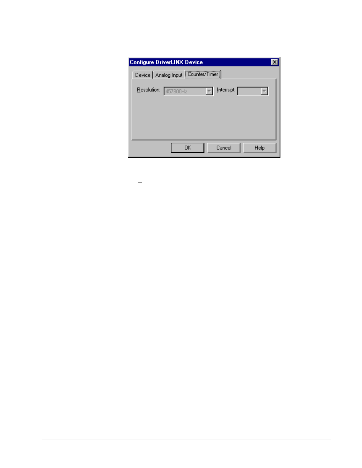
For the DAS-TC/B, there are
no configurable options on
the Counter/Timer subsystem
page.
Counter/Timer Subsystem Page
Resolution
The Resolution property specifies the clock frequency of the master oscillator. The
DAS-TC/B’s master oscillator has a fixed frequency.
Interrupt
The DAS-TC/B does not support interrupts from counter/timers. DriverLINX
disables this property and displays it as blank.
18 • Configuring the DAS-TC/B Keithley DAS-TC/B
Page 19

Using the DAS-TC/B with DriverLINX
Introduction
This chapter shows you how to set up and use DAS-TC/B hardware features with
DriverLINX. See the Analog I/O Programming Guide for an overview of
DriverLINX programming.
The descriptions here use the Edit Service Request dialogs for language and API
independence. For the correct syntax with the language you’re using, please see the
DriverLINX Technical Reference Manuals. For DriverLINX examples in your
programming language, p lease see the sourc e code examples in the subdirectories of
your DriverLINX installation directory or on the original distribution media.
DriverLINX Hardware Model for DAS-TC/B
DriverLINX provides a portable, hardware-independent API for data-acquisition
boards while still allowing applications to access unique or proprietary hardware
features of specific products. To achieve this goal, DriverLINX maps a hardwareindependent, or abstract, data-acquisition model onto DAS-TC/B hardware
capabilities.
The following sections describe how DriverLINX implements DAS-TC/B hardware
features as Subsystems, Modes, Operations, Events, Logical Channels, Buffers, and
Messages.
DriverLINX Subsystems
The DAS-TC/B supports the following DriverLINX’s subsystems:
1. Device—refers to a DAS-TC/B board as a whole.
2. Analog Input—refers to the analog input channels, clocks, and control
signals.
3. Counter/Timer—refers to the internal clock channel for pacing analog
input.
Keithley DAS-TC/B Using the DAS-TC/B with DriverLINX • 19
Page 20

DriverLINX Modes
Applications use modes in Service Requests to advise DriverLINX on their preferred
hardware data transfer technique. The DriverLINX modes fall into two general
classes:
•
Foreground or synchronous modes. The calling application doesn’t
regain control until DriverLINX completes the Service Request.
DriverLINX supports this mode for simple, single-value or single-scan
I/O operations or software housekeeping functions that DriverLINX can
complete without a significant delay.
•
Background or asynchronous modes. The calling application regains
control as soon as DriverLINX initiates the task. The calling application
must synchronize with the data-acquisition task using status polling or
DriverLINX’s messages (preferred). DriverLINX supports this mode
for buffered data transfers or for commands that require a significant
time to complete.
DriverLINX supports three modes with the DAS-TC/B for its commands (Service
Requests).
•
Polled Mode—T his is a foreground or synchronous operation.
DriverLINX supports this mode for simple, single-value I/O operations
that the data-acquisition board can complete without significant delay.
•
Interrupt Mode—Thi s is a background or asynchronous operation.
DriverLINX transfers data between the computer’s memory and the
data-acquisition board using hardware interrupts and programmed I/O
transfers.
•
Other Mode—This is a foreground or synchronous opera tion.
DriverLINX supports this mode for initialization, configuration,
calibration, data conversion, and timebase operations.
The following table summarizes the data acquisition modes that DriverLINX
supports for each subsystem with the Keithley DAS-TC/B.
Subsystem Polled Interrupt Other
Analog Input
Counter/Timer
Device
√√√
√
√
DAS-TC/B Supported DriverLINX Modes.
20 • Using the DAS-TC/B with DriverLINX Keithley DAS-TC/B
Page 21

DriverLINX Operations and Events
Applications construct DriverLINX data-acquisition tasks by combining a small
number of DriverLINX operations and events in many possible ways. The following
table summarizes the operations and events that DriverLINX supports for the
Keithley DAS-TC/B. Later sections for each DriverLINX subsystem describe the
operations and events in more detail.
Note: All subsystems allow the MESSAGE operation and the Analog Input
subsystem allows the CONVERT operation, which are not shown in the table.
DriverLINX allows any Mode setting for these operations.
Subsystem Operation Events
Mode Timing Start Stop
Analog Input
Polled Start null null, cmd null, TC
Interrupt Start, Stop,
Status
Other Initialize
Counter/Timer
Other Initialize
rate cmd cmd, TC
Device
Other Initialize,
Configure,
Capabilities
The following list explains the Event abbreviations in the preceding table:
Logical Channels
DriverLINX designates the individually addressable hardware channels for each
subsystem as “Logical Channels.” Generally, the zero-based Logical Channel
numbering sequence closely follows the hardware manufacturer’s cha nnel numbering
scheme.
Allowed Operations and Events for DAS-TC/B Subsystems and Modes.
•
null—Null or None Event when a Service Request doesn’t require an
event
•
cmd—Command Event when DriverLINX starts or stops a task on
software command
•
TC—Terminal Count Event when DriverLINX processes all data
buffers once
•
rate—Rate Event specifies how DriverLINX paces or clocks data
transfer
In some cases, however, DriverLINX assigns Logical Channel numbers to hardware
features that users don’t commonly think of as “channels.” For instance, on the DAS-
Keithley DAS-TC/B Using the DAS-TC/B with DriverLINX • 21
Page 22

TC/B, DriverLINX models the cold-junction compensation channel as an additional
Logical Channel in the Analog Input Subsystem. In other cases, DriverLINX models
subsystem-specific features, such as internal pacer clocks, as members of a more
general purpose set of counter/timer channels.
For a list of DriverLINX assigned Logical Channel numbers, see the notes on each
supported subsystem.
Buffers
Applications usually use data buffers to exchange data between the application and
the data-acquisition hardware. When using data buffers, please note the following
points about DriverLINX’s data buffers:
•
DriverLINX supports data-acquisition tasks with 1 to 255 data buffers
per task.
•
DriverLINX i mposes no size limits o n a single buffer, alt hough the
operating system or some hardware products may have size restrictions.
•
User applications must allow DriverLINX to allocate all data buffers to
guarantee application portability to different hardware and operating
systems and to insure that the hardware can physically access the buffer
memory.
•
User applications usually don’t have concurrent or immediate access to
the in-use data buffer while DriverLINX is executing a data-acquisition
task.
22 • Using the DAS-TC/B with DriverLINX Keithley DAS-TC/B
Page 23

Connecting Signals to the DAS-TC/B
The Keithley hardware manual describes the data and control signals for the DASTC/B and the connector pinouts for these signals. This section summarizes how
DriverLINX numbers the data signals.
Analog Input Subsystem Signals
The Analog Input subsystem has connections for 16 voltage/thermocouple channels
and one CJC channel.
DriverLINX maps these connections to Logical Channels as shown in the following
table:
Physical Channel Connector Names Logical
Channel
0 – 15
Voltage/Thermocouple
CJC Channel CJC Voltage Input, CJC Return 16
How DriverLINX maps analog input hardware channels to Logical Channels.
Channel 0 – 15 Low, High Inputs 0 – 15
Keithley DAS-TC/B Using the DAS-TC/B with DriverLINX • 23
Page 24

Device Subsystem
The following sections describe how DriverLINX implements Device Subsystem
features for the DAS-TC/B.
Device Modes
The Device Subsystem only supports DriverLINX’s Other mode for all operations.
Device Operations
The DAS-TC/B Device Subsystem supports the following DriverLINX operations:
If another application is using
the same data-acquisition
board, DriverLINX will
prevent Device Initialization
from interfering with another
application’s data-acquisition
tasks.
•
Initialize—DriverLINX aborts all data-acquisition tasks for every
subsystem controlled by the current application. DriverLINX then
performs an initialization for each supported subsystem.
•
Configure—DriverLINX displays the Configure DriverLINX Device
dialog for the current Logical Device. Please use the DriverLINX
Configuration Panel rather than this operation to configure
DriverLINX.
•
Capabilities—DriverLINX provides hardware-specific and
configuration information in the form of a Logical Device Descriptor
database.
24 • Using the DAS-TC/B with DriverLINX Keithley DAS-TC/B
Page 25

Analog Input Subsystem
The following sections describe how DriverLINX implements Analog Input
Subsystem features for the DAS-TC/B.
Analog Input Modes
The Analog Input Subsystem supports the following modes:
•
Polled—For single-value or scan analog-input samples.
•
Interrupt—For buffered transfers using programmed I/O.
•
Other—For subsystem initialization and data conversion.
Analog Input Operations
The DAS-TC/B Analog Input Subsystem supports the following DriverLINX
operations:
•
Initialize—aborts all active analog input data-acquisition tasks.
However, DriverLINX prevents one application from interfering with
another application’s data-acquisition tasks.
•
Start—initiates a data-acquisition task using the Mode, Timing, Start,
and Stop Events, the Logical Channels, and the Buffers the application
specified in the Service Request.
•
Status—reports the buffer position of the next sample that DriverLINX
will write into a buffer.
•
Stop—terminates an analog input data-acquisition task.
•
Message—DriverLINX displays a pop-up dialog box for the user
containing the text for the current DriverLINX error message.
Keithley DAS-TC/B Using the DAS-TC/B with DriverLINX • 25
Page 26

Analog Input Timing Events
Timing Events specify how the hardware paces or clocks the acquisition of analog
input samples. DriverLINX uses the Timing Event to program when the DAS-TC/B
acquires the next analog input sample.
The DAS-TC/B supports the following Timing Events:
•
None—Sampling requires no pacing as DriverLINX is acquiring only a
single value or scan.
•
Rate—The DAS-TC/B supports fixed rate and burst mode sampling
using an internal clock in interrupt mode.
None or Null Event
The Null Event specifies that the task does not need a clock to determine when to
acquire the next sample. Such tasks include:
•
Single Value—Acquires a single sample from a single channel.
•
Single Scan—Acquires one sample from each channel in the channel
list or range and stores them in a buffer.
Rate Event
The DAS-TC/B supports two types of Rate Events for analog input:
•
Rate Generator—Generates a fixed rate clock with equal time
intervals between tics.
•
Burst Generator—Generates a dual frequency clock with a fixed
number of tics at a high frequency separated by a time interval at a
lower frequenc y.
26 • Using the DAS-TC/B with DriverLINX Keithley DAS-TC/B
Page 27

Null Event: Single Value
The Null Event specifies that the task does not need a clock to determine when to
acquire the next sample.
Use a Null Event to acquire a single sample from one channel in Polled mode.
How to set up the DAS-TC/B to acquire a single sample using a Null Timing Event.
•
Specify Polled Mode.
•
Specify a Null Timing Event by selecting None under Timing.
•
Select the channel to acquire—see “Analog Input Channels” on page
33.
•
Select the buffer for the sample—see “Analog Input Buffers” on page
40.
Keithley DAS-TC/B Using the DAS-TC/B with DriverLINX • 27
Page 28

Null Event: Single Scan
The Null Event specifies that the task does not need a clock to determine when to
acquire the next sample.
Use a Null Event to acquire a single scan (one sample each from a number of
channels) in Polled mode.
How to set up the DAS-TC/B to acquire a single scan using a Null Ti ming E vent.
•
Specify Polled Mode.
•
Specify a Null Timing Event by selecting None under Timing.
•
Select the channels to acquire—see “Analog Input Channels” on page
33.
•
Select the buffer for the samples. The buffer must hold exactly one
scan. See “Analog Input Buffers” on page 40.
28 • Using the DAS-TC/B with DriverLINX Keithley DAS-TC/B
Page 29

Rate Generator: Internal Clocking
An internally clocked Rate Generator produces a fixed rate clock with equal time
intervals between tics.
Period
Use an internally clocked rate generator when you want to acquire all analog input
samples at equally spaced time intervals.
For hardware independence,
specify the clock channel
using the symbolic constant,
DEFAULTTIMER, which
always maps to the default
Logical Channel for analog
input timing.
How to set up the DAS-TC/B for fixed rate sampling using an int ernal clock.
•
Specify Interrupt Mode.
•
Specify internal cl ocking using a Rate Generator on Channel 0 with
the Internal 1, 2, 3 or 4 Clock source. See “Counter/Timer
Subsystem” on page 43 for a description of clock sources.
•
The Period property specifies the time interval between samples in tics,
where a tic is 2.18436 µs, or 458 kHz. The minimum period is 228900
tics (0.5 seconds). The maximum period is 65535 tics (27.3 minutes).
The minimum period may be increased by the DAS-TC/B’s sample
averaging feature (see “Sample Averaging on the DAS-TC/B” on page
39).
•
Specify the Gate property as Disabled. The DAS-TC/B does no t have
hardware gating.
•
The channel Simultaneous property determines whether the DAS-TC/B
samples a single channel or an entire scan in each Period. If you select
simultaneous, the DAS-TC/B samples the channels in the scan at the
rate determined by the Clock source. See “Counter/Timer Subsystem”
on page 43 for details on clock sources.
Keithley DAS-TC/B Using the DAS-TC/B with DriverLINX • 29
Page 30
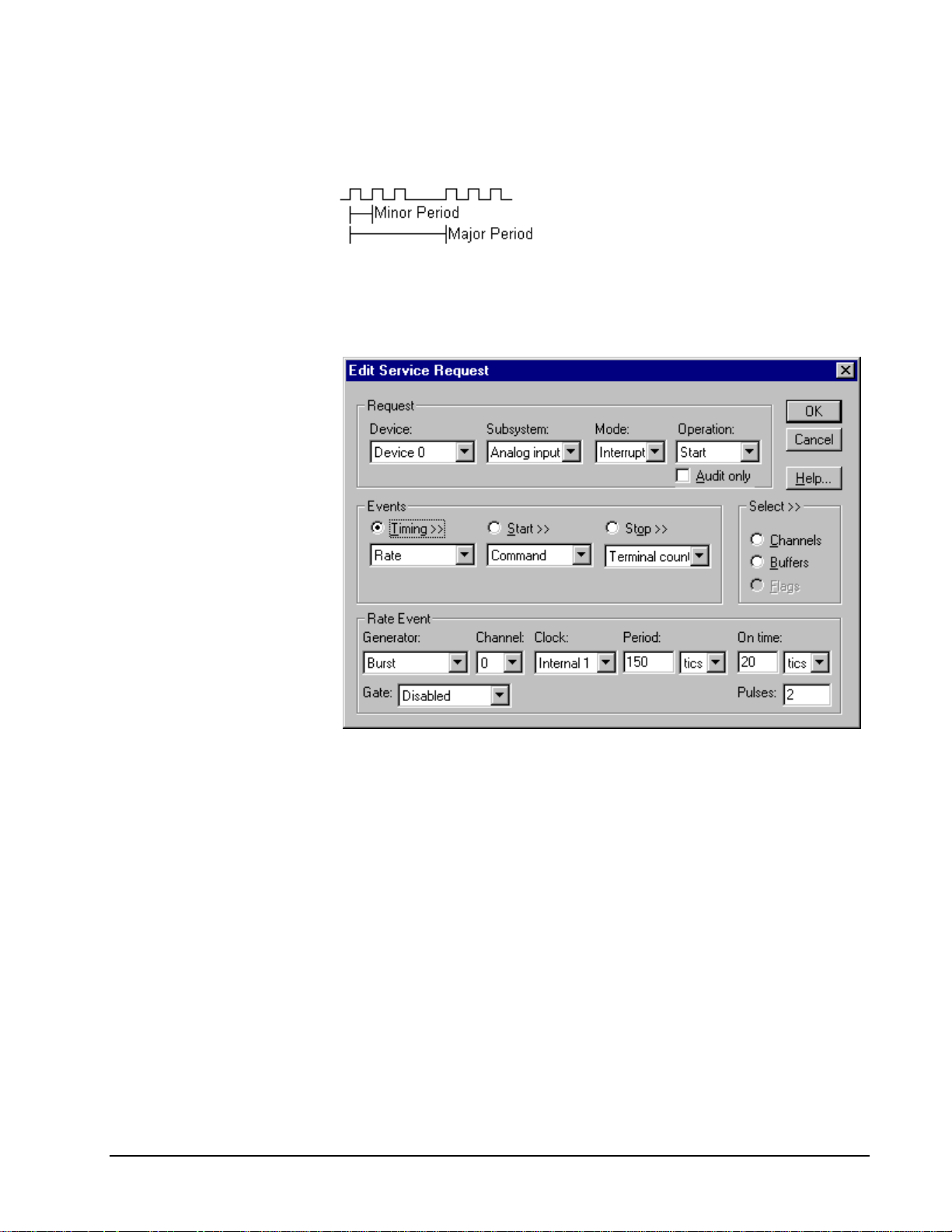
Burst Generator: Internal Clocking
An internally clocked Burst Generator produces a dual frequency clock with a fixed
number of tics at a high frequency repeated at a lower frequency.
Use an internally clocked rate generator when you want to acquire analog input
samples from a several channels at closely spaced time intervals and then repeat at
longer intervals.
How to set up the DAS-TC/B for burst mode sampling using an internal cl ock.
For hardware independence,
specify the clock channel
using the symbolic constant,
DEFAULTTIMER, which
always maps to the default
Logical Channel for analog
input timing.
•
Specify Interrupt Mode.
•
Specify internal cl ocking using a Burst Generator on Channel 0 with
the Internal 1 Clock source. See “Counter/Timer Subsystem” on page
43 for a description of clock sources.
•
The Period property specifies the time interval between bursts in tics,
where a tic is 2.18436 µs, or 458 kHz. The minimum period is 228900
tics (0.5 seconds). The maximum period is 65535 tics (27.3 minutes).
•
The On time property specifies the time interval between samples. It
must be within the range of 18312 tics minimum to 2289 tics
maximum. The driver rounds values in the valid range to the nearest
hardware value: 18312, 15260, 2289. Also On time × SUM AVG + 2
must be less than or equal to Period, where SUM AVG is the sum of
the AVG settings for all the channels in the scan list. (See “Sample
Averaging on the DAS-TC/B” on page 39.)
30 • Using the DAS-TC/B with DriverLINX Keithley DAS-TC/B
Page 31

•
Specify the Gate property as Disabled. The DAS-TC/B does not have
hardware gating.
•
The Pulses property specifies how many channels the board samples in
each Period. Pulses must be equal the number of channels in the
channel list.
Analog Input Start Events
Start Events specify when the DAS-TC/B hardware starts acquiring analog input
data.
The DAS-TC/B supports the following Start Events:
•
None—Use this event when the DriverLINX operation does not require
a Start Event.
•
Command—DriverLINX starts the task on software command, i.e., as
soon as DriverLINX finishes programming the DAS-TC/B hardware for
the task.
None or Null Event
The Null Event specifies that the task does not need a Start Event to begin the task.
Command Event
The Command Event starts data acquisition as soon as DriverLINX has completed
programming the data-acquisition hardware with the task parameters.
Analog Input Stop Events
Stop Events specify when the hardware stops acquiring analog input data.
The DAS-TC/B supports the following Stop Events:
•
None—Use this event when the DriverLINX operation doesn’t require
a Stop Event.
•
Command—Dr iverLINX stops the task on software command, i.e.,
when the application issues a Service Request with a Stop operation.
•
Terminal count—DriverLINX stops the task after the data-acquisition
hardware has filled all the data buffers once.
None or Null Event
The Null Event specifies that the task does not need a Stop Event to end the task.
Command Event
The Command Event stops data acquisition when the user application changes the
Operation property in the Service Request to Stop and resubmits the Service Request
to DriverLINX.
In Stop-on-Command mode , DriverLINX continuously cycles through al l the data
buffers filling them with analog input data from the data-acquisition hardware.
Keithley DAS-TC/B Using the DAS-TC/B with DriverLINX • 31
Page 32

Terminal Count Event
The Terminal Count Event stops data acquisition after DriverLINX has filled all the
data buffers once with analog input data. Use Terminal Count when you want to
acquire a single scan or fixed amount of data.
32 • Using the DAS-TC/B with DriverLINX Keithley DAS-TC/B
Page 33

Analog Input Channels
Channel specifications include channel numbers as well as a gain code for each
channel. DriverLINX defines a specialized gain code format to support the DAS-
TC/B’s voltage, thermocouple and CJC channels.
The DAS-TC/B allows applications to specify the analog channels and gains using
three techniques:
•
Start Channel—Acquire data from a single channel.
•
Start/Stop Channel Range—Acquire data from a consecutive range of
channels.
•
Channel List—Acquire data from a list of channels.
Single Channel Analog Input
In single channel mode, the DAS-TC/B acquires all data from one channel at the
specified gain.
How to set up the DAS-TC/B for sampling on a single channel.
Multi-channel Analog Input Range
In multi-channel range mode, the DAS-TC/B acquires data from a consecutive range
of analog channels.
•
The Start Channel’s gain only applies to the first channel.
•
The Stop Channel’s gain applies to all the other analog channels in the
range.
•
The Start Channel must be less than or equal to the Stop Channel.
Setting the Start Channel equal to the Stop Channel specifies a single
channel.
Keithley DAS-TC/B Using the DAS-TC/B with DriverLINX • 33
Page 34

How to set up the DAS-TC/B for sampling on a consecutive range of channels.
Multi-channel Analog Input List
In multi-channel list mode, the DAS-TC/B acquires data from a arbitrary list of
analog channels.
•
The channel-gain list may contain up to 16 channels (17 if it ends with
the CJC channel) in any order and with any allowed gain.
•
The list may repeat the same channel with the same gain.
•
The list can contain the CJC channel (Logical Channel 16) but only
once and it must be last.
34 • Using the DAS-TC/B with DriverLINX Keithley DAS-TC/B
Page 35

How to set up the DAS-TC/B to sample on a arbitrary list of channels.
Keithley DAS-TC/B Using the DAS-TC/B with DriverLINX • 35
Page 36

Analog Input Gain Codes
The DAS-TC/B supports a variety of voltage and thermocouple gains. Applications
can select the channel type, sample averaging, cold-junction compensation and, gain
or temperature units using the channel ga i n code. However, by using a gain code o f
zero, applications can default to the user-assigned settings in Configure DriverLINX
Device dialog.
The following tables show the correspondence between DriverLINX gains, the
maximum input signal range, and the gain code for each input range. You can use
either a Voltage gain or a Thermocouple gain with Logical Channels 0 to 15. The
CJC channel (Logical Channel 16) supports only two specialized gain codes.
Voltage Gains
Gain Multiplier Range Gain Code
-1 -2.5 to + 10 V 1
-125 -20 to +80 mV 2
-166.7 -15 to +60 mV 3
-400 -6.25 to +25 mV 4
Voltage Gain Multipliers, Ranges, and Gain Codes.
Note: DriverLINX uses a negative (-) gain value to signify a bipolar (±) range.
For each voltage channel, you can select the gain multiplier, sample averaging, and
cold-junction compensation using the channel gain code. Use a gain code of zero to
default to the user-assigned settings in Configure DriverLINX Device dialog.
To set up a voltage gain code :
1. Use the DriverLINX Gain2Code method to convert a gain multiplier to
the corresponding gain code.
2. Add the constant CJCon if you want cold-junction c ompensation.
3. Add the number of measurements times the constant SampleAveraging
if you want to obtain an averaged sample rather than an instantaneous
sample.
Thermocouple Gains
TC Type Range Gain Code
TCTypeB 400 to 1700 C 5
TCTypeE -200 to 1000 C 6
TCTypeJ -200 to 750 C 7
TCTypeK -200 to 1250 C 8
TCTypeR 0 to 1768 C 9
TCTypeS 0 to 1450 C 10
TCTypeT -200 to 400 C 11
TCTypeN 246 to 1300 C 13
Thermocouple Types, Ranges, and Gain Codes.
36 • Using the DAS-TC/B with DriverLINX Keithley DAS-TC/B
Page 37

For each thermocouple channel, you can select the thermocouple type, degree units,
sample averaging, and cold-junct ion compensation using t he channel gain code. Use
a gain code of zero to default to the user-assigned settings in Configure DriverLINX
Device dialog.
To set up a thermocouple gain code:
1. Select the TC Type constant for the type of thermocouple attached to
the channel.
2. Add the constant CJCon if you want cold-junction c ompensation.
3. Add a number times the constant SampleAveraging if you want to
obtain an averaged sample rather than an instantaneous sample.
4. Add either the constant Fahrenheit or the constant Celsius to select a
temperature unit.
CJC Channel Gains
Gain Gain Code
CJCVolts 0
CJCCelsius -32768
CJC Channel Gains and Gain Codes.
For the CJC channel, you can select volts or degree Celsius using the channel gain
code.
To set up a CJC channel gain code:
Select either the constant CJCVolts or the constant CJCCelsius.
Keithley DAS-TC/B Using the DAS-TC/B with DriverLINX • 37
Page 38

The following table lists constants that will assist you in constructing gain codes.
Constants for Constructing Gain Codes
Constant Value
CJCoff
CJCon
SampleAveraging
TCTypeB
TCTypeE
TCTypeJ
TCTypeK
TCTypeR
TCTypeS
TCTypeT
TCTypeN
Celsius
Fahrenheit
CJCVolts
CJCCelsius
13
20×
13
21×
6
2
532768+−
632768+−
732768+−
832768+−
932768+−
1032768+−
1132768+−
1332768+−
14
20×
14
21×
0
32768−
38 • Using the DAS-TC/B with DriverLINX Keithley DAS-TC/B
Page 39

Sample Averaging on the DAS-TC/B
Using its onboard microprocessor, the DAS-TC/B can take multiple measurements of
the signal on a channel and return their average as the sample value. This sampling
technique reduces the effect of some types of noise on the data. However, it does
change the timing of the samples, increasing the time between sampling each channel
and potentially reducing the maximum sample frequency. Both the user, through
configuration, and the develo per, through the application, can specify sample
averaging. Whether you are a user or developer, you should be aware of how to set
up sample averaging and its effects on timing.
Users can set up sample averaging for a Logical Device from the DriverLINX
Configuration Panel
See “Special…” on page 14 for more information.
Developers can accept or override a channel’s configured setting for sample
averaging in an application’s service request. If the channel’s gain code equals zero
then DriverLINX uses the configured setting for that channel. Otherwise, the gain
code includes the number of measurements to average for each same value. See
“Analog Input Gain Codes” on page 36 for details on constructing gain codes for the
DAS-TC/B.
Each channel sampled by a data-acquisition task has a setting for the number of
measurements to average, whether specified in the service request or taken from the
configuration. In each sample interval (DriverLINX’s period setting), the board
attempts to obtain all the measurements of the task’s channels and return the
averaged sample values. The period should be long enough to meet he board’s timing
requirements.
. Each channel has a separate setting for sample averaging.
The figure below illustrates the timing requirements by showing samples from two
channels. Samples from the first channel are the average of four measurements;
samples from the second channel are the average of six measurements. The DASTC/B takes measurements at a rate of NMRF / 2 (DriverLINX’s onCount or On time
setting) and requires at least two extra cycles in each period.
If the period is not long enough, the DAS-TC/B simply delays the next sa mpl e period
until it is done taking all the requested measurements. This can cause an application
to receive samples at a rate different than requested. If an application is not behaving
as expected, users can try configuring the AVG setting for each channel to one.
Developers should see “Analog Input Messages” on page 42 for tips on determining
the actual timing of samples.
Keithley DAS-TC/B Using the DAS-TC/B with DriverLINX • 39
Page 40

Analog Input Buffers
DriverLINX supports both single-value analog input and buffered analog input.
•
For single-value input, specify the Number of buffers as 0. The buffer
for a single value is the ioValue property.
•
For single-scan input, specify the Number of buffers as 1 and the
number of Samples equal to the number of channels.
•
For buffered input, specify the Number of buffers from 1 to 256 and
the number of Samples as desired.
For example, 500 samples/2
channels = 250 is ok, but 500
samples/3 channels = 166.67
is incorrect.
How to set up the DAS-TC/B to store samples in buffers.
An individual DriverLINX buffer may have any size as long as the buffer length
holds an integral number of channel scans (i.e., a multiple of the number of analog
input channels you’re acquiring). This restriction enforces the requirement that all
acquired channels have the same number of sample s.
Analog Input Data Coding
The DAS-TC/B returns analog-to-digital values in either of two formats,
automatically applying offsets and gains for the selected engineering units:
•
Standard 32-bit, single-precision floating-point number. Values are in
degrees or volts
•
Scaled 32-bit two’s complement integer. Values are in thousandths of
degrees or millionths of volts
DriverLINX refers to the floating-point format as the “native” format and the integer
format as “long.” The native format is the same as DriverLINX’s “single” format.
Applications can request data in any of the three formats using the channel Format
property of the service request.
40 • Using the DAS-TC/B with DriverLINX Keithley DAS-TC/B
Page 41

DriverLINX’s data conversion operations can transform an entire data buffer from
native format to many common intege r and floating-point formats. For the DASTC/B, applications can request a conversion from “single” to “long” or “double.” See
the DriverLINX Technical Reference Manuals for more information.
Keithley DAS-TC/B Using the DAS-TC/B with DriverLINX • 41
Page 42

Analog Input Messages
For analog input operations, DriverLINX can report the following messages to the
application:
DriverLINX
Explanation
Message
Service Start DriverLINX has started the acquisition task.
Service Done DriverLINX has completed the acquisition task.
Buffer Filled DriverLINX has filled an analog input buffer.
Data Lost DriverLINX has detected an analog input data overrun
condition.
Critical Error DriverLINX has encountered an unexpected hardware
or software condition.
DriverLINX Event mess ages for analog input.
Data Lost
DriverLINX notifies applications that a buffer overrun has occurred by posting an
event message, DL_DATALOST. DriverLINX posts this message only the first time
the board detects an overrun during an acquisition task and then stops the task.
Most data-acquisition models attempt to obtain samples at strictly timed intervals and
report “Data Lost” when they cannot obtain or buffer a sample value. The DASTC/B, however, can take multiple measurements from a channel, returning their
average as the sample value. It does not report “Data Lost” if it still is obtaining
measurements for one interval when the next interval should begin—it simply
extends the sampling interval as necessary to obtain all the requested measurements.
(See “Sample Averaging on the DAS-TC/B” on page 39 for more information on
sample timing.)
As a result of the DAS-TC/B’s flexible timing, DriverLINX cannot provide a
definitive timebase that gives the relative time of samples. Applications should use
the system time upon receipt of a Buffer Filled message to determine if the sample
timing meets the application’s requirements.
42 • Using the DAS-TC/B with DriverLINX Keithley DAS-TC/B
Page 43

Counter/Timer Subsystem
Clocks
Tic Period
The DAS-TC/B has a counter/timer for analog input pacing only.
The following table lists the Counter/Timer Subsystem’s Logical Channels and shows
their allowable clock sources, modes and gates:
Logical
Modes Gates
Channels Source
0Internal12.189141856392 µs Rate Gen* Disabled
Burst Gen No Connect
Internal2 2.189141856392 µs Rate Gen*
Internal3 2.189141856392 µs
Internal4 2.189141856392 µs
Counter/Timer Subsystem Logical Channels and Allowed Clocks, Modes and Gates.
*A Rate Gen with “simultaneous” sampling is an alias for a burst generator. The
Clock Source selects the implicit minor period as follows:
•
Internal1—2/NMRF configuration setting (equivalent to one of the
following)
•
Internal2—2/50Hz = 25Hz= 40 ms = 18272 tics
•
Internal3—2/60Hz = 30 Hz = 33.333 ms = 15227 tics
•
Internal4—2/400Hz = 200 Hz = 5 ms = 2284 tics
Keithley DAS-TC/B Using the DAS-TC/B with DriverLINX • 43
Page 44

Page 45

Uninstalling DriverLINX
How do I uninstall DriverLINX?
DriverLINX consists of three separate component installations:
•
DriverLINX for Keithley DAS-TC/B
•
DriverLINX Programming Interfaces
•
DriverLINX Documentation
You can uninstall the last two installations at any time without interfering with
compiled applications that require DriverLINX drivers. To uninstall the latter
components, run the “Add/Remove Programs” tool in the Windows Control Panel.
To uninstall DriverLINX drivers for the Keithley DAS-TC/B, you must
•
Disable the DriverLINX driver.
•
Shut down your computer to remove the hardware.
•
Reboot your computer to unload the driver.
•
Run the DriverLINX uninstall program.
How to Disable a DriverLINX Driver in Windows NT
1. From the Windows Start menu, select “Settings”, then “Control Panel”.
Left click on the DriverLINX Configuration icon in the Control Panel.
2. Select the DAS-TC/B devices you want to disable.
3. Right click on each device and select “Disabled” on the popup menu.
4. Repeat steps 2-3 for each DAS-TC/B card that you are uninstalling.
5. Close the DriverLINX Configuration Panel.
6. When finished, shut down your computer and physically remove any
installed DAS-TC/B hardware.
7. Reboot Windows.
8. To finish uninstalling, see “How to Remove DriverLINX for Keithley
DAS-TC/B” on page 46.
Keithley DAS-TC/B Uninstalling DriverLINX • 45
Page 46

How to Disable a DriverLINX Driver in Windows 95/98
1. From the Windows Start menu, select “Settings”, then “Control Panel”.
Left click on the System icon in the Control Panel. Select the “Device
Manager” tab in the System Properties dialog.
2. Left click the “+” icon next to “DriverLINX drivers” to display the
installed Keithley DAS-TC/B devices.
3. Select the DAS-TC/B device you want to disable.
4. Click the “Remove” button.
5. In the “Confirm Device Removal” dialog, select “OK”.
6. Repeat steps 3-5 for each DAS-TC/B card or driver that you
uninstalling.
7. When finished, click “Close”, shut down your computer, and physically
remove any installed DAS-TC/B hardware.
8. Reboot Windows.
9. To finish uninstalling, see “How to Remove DriverLINX for Keithley
DAS-TC/B” on page 46.
How to Remove DriverLINX for Keithley DAS-TC/B
1. From the Windows Start menu, select “Settings”, then “Control Panel”.
Left click on the Add/Remove Programs icon in the Control Panel.
2. Select “DriverLINX for Keithley DAS-TC/B” in the Add/Remove
Programs Properties dialog.
3. Click the “Add/Remove…” button.
4. Answer “Yes” to “Are you sure you want to remove ‘DriverLINX for
Keithley DAS-TC/B’ and all of its components?” in the Confirm File
Deletion dialog.
5. The DriverLINX uninstall program will proceed.
The uninstall program will not remove the folder, “\DrvLINX4\System”. This folder
contains copies of any \Windows\System or \Windows\System32 files that the
original DriverLINX installation updated.
46 • Uninstalling DriverLINX Keithley DAS-TC/B
Page 47

Troubleshooting
Solving Problems
Correct operation of your DAS-TC/B hardware requires successful completion of
four steps.
1. Windows finds free resources for the DAS-TC/B board.
2. The DAS-TC/B address switches are set to the assigned address
resource.
3. You configure the DAS-TC/B drivers using the DriverLINX
Configuration Panel.
4. Windows loads the DAS-TC/B drivers into memory.
If you are having a problem installing or configuring your DAS-T C/B product,
review the following notes. If these notes do not solve your problem, or your problem
is not described, then contact technical support and fully describe your problem.
Solving Problems Installing Drivers
On Windows NT, the DriverLINX installation program reliably installs and registers
the DriverLINX drivers. On Windows 95/98, the DriverLINX installation program
runs a wizard that guides you through installing the DriverLINX drivers. If the
wizard did not complete all steps, click here
to run it again.
Solving Problems Configuring the Drivers
Windows 95/98 assigns hardware resources for the DAS-TC/B, but you must still
configure the DAS-TC/B drivers before using them. The DriverLINX configuration
requires that you select the hardware model of your DAS-TC/B board. And, on
Windows NT, you must manually enter the address and interrupt resource
assignments. See “Configur i ng the DAS-TC/B” on page 11 for more information.
Keithley DAS-TC/B Troubleshooting • 47
Page 48

Solving Problems Loading Drivers
Before the DAS-TC/B drivers can load, you must
1. Install the DriverLINX software.
2. Install the DAS-TC/B hardware into your computer.
3. Configure Drive rLINX.
4. Reboot your computer.
If you have not completed the above steps, please do so before proceeding.
On Windows NT you must determine free hardware resources for the DAS-TC/B
using Windows NT Diagnostics
automatically assign hardware resources to the DAS-TC/B cards. Automatic resource
assignment can fail sometimes on
•
Older PCI computers.
•
Computers with ISA cards installed.
•
Computers with no free hardware resources .
Sorting through all possibilities can be a challenge due to the she e r number of
combinations of hardware designs, PC plug-in boards, and versions of Windows. The
following sections will help you gather information about why a driver may have
failed to load. This information is essential for you or technical support to solve your
problem.
. On Windows 95/98, the operating system will
Did the DriverLINX Driver Load?
1. Run “DriverLINX Configuration” from Windows Control P anel.
2. Select the “DriverLINX” tab.
3. Click the “+” icon next to DriverLINX to expand the list of drivers, if
necessary.
4. Select “Keithley DAS-TC/B”. Click “+”, if necessary, to expand the
list.
5. Select the line with the number of the Logical Device you configured. If
the number does not exist, you did not configure the driver. See
“Configuring the DAS-TC/B” on page 11.
6. Click the “Properties…” button and then select the “General” tab.
7. Do you see “Status: Device Loaded”? If not, did you reboot the
computer after configuring? If not, reboot now and repeat the above
steps.
48 • Troubleshooting Keithley DAS-TC/B
Page 49

8. If you rebooted the computer after configuring and Windows did not
load your device, see “Checking for Device Errors” on page 49.
Checking for Device Errors
When a DriverLINX kernel driver cannot load, it usually writes an explanation into
the system event log. You can view this log under Windows 95/98 or Windows NT
using the DriverLINX Event Viewer.
Windows 95/98 maintains additional driver information in the Device Manager. Also
see “Getting More Driver Information on Windows 95/98” on page 49.
1. Run “DriverLINX Event Viewer” from the DriverLINX folder.
2. Click on the “+” icon next to “DriverLINX” in the left panel.
3. Select the abbreviation for your driver.
4. Does the first line in the right panel show a current error?
5. Double click on the error line to see more detail and an explanatory
message.
6. If you cannot resolve the problem yourself, please provide this error
information when contacting technical support.
Getting More Driver Information on Windows 95/98
Windows 95/98 reports additional information about device status using the Device
Manager. To access this utility,
1. Right click on “My Computer” and then select “Properties”.
2. Select “Device Manager” and “View devices by type”.
3. Does “DriverLINX drivers” appear in the list? If not, see “Solving
Problems Installing Drivers” on page 47.
4. Click the “+” next to “DriverLINX drivers”.
5. Does your DAS-TC/B product appear in the list? If not, see “Solving
Problems Installing Drivers” on page 47.
6. Does the icon next to your DAS-TC/B product display an exclamation
point (!)? If no, Windows has loaded your DAS-TC/B driver.
7. Select the line with the “!” and then click “Properties”.
Keithley DAS-TC/B Troubleshooting • 49
Page 50

8. The General tab will show the reason why the driver did not load.
9. The Resources tab will show if Windows detected an unresolvable
hardware conflict.
Getting More Driver Information on Windows NT
On Windows NT, the only reasons that a driver does not load are
•
You did not install the driver software.
•
You did not correctly configure the driver.
•
You changed the driver startup parameters.
An incorrectly configured driver will report the reasons that it failed to load into the
Windows Event Log. See “Checking for Device Errors” on page 49 for more
information.
On Windows NT, DriverLINX drivers load automatically during system boot. An
administrator can change the startup command for any NT driver to either “manual”
or “disabled”.
1. Run “DriverLINX Configuration” from Windows Control P anel.
2. Select the “DriverLINX” tab.
3. Click the “+” icon next to DriverLINX to expand the list of drivers, if
necessary.
4. Select “Keithley DAS-TC/B”. Click “+”, if necessary, to expand the
list.
5. Select the line with the number of the Logical Device that did not load.
6. Right click the mouse to see a popup menu.
7. Select “Automatic” to instruct Windows to load the driver the next time
you reboot.
50 • Troubleshooting Keithley DAS-TC/B
Page 51

Generating a DriverLINX Configuration Report
Your DriverLINX installation includes a troubleshooting tool that generates a report
of your DriverLINX configuration. If you call Technical Support, after reading
“Solving Problems” on page 47, they may ask you to generate and e-mail this report
to help you solve installation and configuration problems.
What is in the Report?
The troubleshooting tool analyzes your computer to obtain information about
DriverLINX and operating system software that would assist Technical Support in
troubleshooting a problem you are having. It i ncludes information on DriverLIN X
files, environment variables, registry entries, hardware and the operating system.
How do I Generate the Repor t?
You can easily generate the report by clicking this shortcut . Once the
troubleshooting tool generates the report, you will have the opportunity to review it
and make deletions, if desired, before e-mailing it to Technical Support. If you do not
have direct access to e-mail, you can save the report to a disk file and send a copy
later. A Technical Support engineer will guide you through these steps when you are
asked to send a report.
Keithley DAS-TC/B Troubleshooting • 51
Page 52

Glossary of Terms
A/D
Abbreviation for Analog-to-Digital, a process that converts a continuous analog
signal into a discrete digital approximation of the analog signal.
ADC
Abbreviation for Analog-to-Digital Converter, the hardware that performs the A/D
conversion.
API
Abbreviation for Application Programming Interface. An API defines the syntax of
the data structures and functions of software services.
Buffer
A block of memory used to receive data from a data-acquisition device or to write
data to a data-acquisition device.
Clocking
A periodic pulse or signal that data-acquisition hardware uses to read or write the
next sample or block of samples. Also referred to as “pacing”.
D/A
Abbreviation for digital-to-analog, a process that converts a discrete digital value into
a continuous analog voltage representing that value.
DAC
Abbreviation for digital-to-analog converter, the hardware that performs the D/A
conversion process.
DMA
Abbreviation for Direct Memory Access, a technique where the system board can
transfer data between a device and memory without using the CPU. In the PC, a
standard chip on the system board controls the transfer.
F-52 • Generating a DriverLINX Configuration Report How do I Generate the Report?
Page 53

Event
For DriverLINX, an event is the occurrence of a signal that clocks, starts, or stops a
data-acquisition task.
Gating
A signal that enables and disables another signal or data-acquisition task depending
on the value of the gate signal.
IRQ
Abbreviation for interrupt request. Peripheral hardware signals the CPU that it is
ready to transfer data.
ISA
Abbreviation for Industry Standard Architecture. A standard for the original IBM AT
bus specification that defines the bus structure, CPU and support chip architecture,
and the clock frequency of the ISA bus.
ISR
Abbreviation for interrupt service routine, the software function inside a device
driver that handles interrupt requests.
Logical Device
DriverLINX’s designation for a specific data-acquisition board inside your computer.
Messages
In Windows and DriverLINX, a message notifies the application about the state of a
process.
Modes
DriverLINX data-acquisition techniques.
Operations
Allowed DriverLINX data-acquisition commands.
Pacing
A periodic pulse or signal that data-acquisition hardware uses to read or write the
next sample or block of samples. Also referred to as “clocking”.
Process
Refers to the collection of data and code segments and hardware resources that the
operating system assigns to one application.
Scan
One sample for each entry in a data-acquisition task’s scan, or channel, list.
Glossary of Terms Generating a DriverLINX Configuration Report • F-53
Page 54

Service Request
A DriverLINX object or data structure that completely defines a data-acquisition
task.
Subsystem
DriverLINX subdivides a general purpose data-acquisition device into six
subsystems—Device, Analog Input, Analog Output, Digital Input, Digital Output,
and Counter/Timer.
Triggering
The technique of using a pulse or signal to start or stop a data-acquisition task.
TTL
Abbreviation for transistor-transistor logic, a family of digital logic elements.
F-54 • Generating a DriverLINX Configuration Report How do I Generate the Report?
 Loading...