

Page 1

Keithley DAS-800 Series
Using DriverLINX with Your
Hardware
Page 2

Information in this document is subject to change without notice. The software
described is this document is furnished under a license agreement. The software may
be used or copied only in accordance with the terms of the agreement.
SCIENTIFIC SOFTWARE TOOLS, INC. SHALL NOT BE LIABLE FOR ANY
SPECIAL, INCIDENTAL, OR CONSEQUENTIAL DAMAGES RELATED TO
THE USE OF THIS PRODUCT. THIS PRODUCT IS NOT DESIGNED WITH
COMPONENTS OF A LEVEL OF RELIABILITY SUITABLE FOR USE IN LIFE
SUPPORT OR CRITICAL APPLICATIONS.
This document may not, in whole or in part, be copied, photocopied, reproduced,
translated or reduced to any electronic medium or machine readable form without
prior written consent from Scientific Software Tools, Inc.
Keithley DAS-800 Series: Using DriverLINX with Your Hardware
Copyright 1998-2000 by Scientific Software Tools, Inc.
All rights reserved.
Third Printing.
SST 18-0300-1
DriverLINX, SSTNET, and LabOBJX are registered trademarks and
DriverLINX/VB is a trademark of Scientific Software Tools, Inc.
MetraByte is a trademark of Keithley Instruments, Inc.
Microsoft and Windows are registered trademarks and Visual C++ and Visual Basic
are trademarks of Microsoft Corporation.
Borland is a registered trademark and Borland C++ and Delphi are trademarks of
Borland International, Inc.
All other brand and product names are trademarks or registered trademarks of their
respective companies.
Page 3

Contents
Preface 5
Software License and Software Disclaimer of Warranty............................................................5
About DriverLINX.....................................................................................................................7
About This User’s Guide...........................................................................................................7
Conventions Used in This Manual.............................................................................................9
Configuring the DAS-800 Series 11
Introduction..............................................................................................................................11
Configure DriverLINX Device Dialog.....................................................................................11
Using the DAS-800 Series with DriverLINX 23
Introduction..............................................................................................................................23
DriverLINX Hardware Model for DAS-800 Series.................................................................23
Connecting Signals to the DAS-800 Series..............................................................................27
Device Subsystem....................................................................................................................30
Analog Input Subsystem ..........................................................................................................31
Device Subsystem Page.............................................................................................13
Analog Input Subsystem Page ...................................................................................17
Digital Input Subsystem Page....................................................................................18
Digital Output Subsystem Page .................................................................................20
Counter/Timer Subsystem Page.................................................................................22
DriverLINX Subsystems............................................................................................23
DriverLINX Modes ...................................................................................................24
DriverLINX Operations and Events..........................................................................25
Logical Channels.......................................................................................................26
Buffers.......................................................................................................................26
Analog Input Subsystem Signals................................................................................27
Digital Input Subsystem Signals................................................................................28
Digital Output Subsystem Signals..............................................................................28
Counter/Timer Subsystem Signals.............................................................................29
Device Modes............................................................................................................30
Device Operations .....................................................................................................30
Analog Input Modes..................................................................................................31
Analog Input Operations............................................................................................31
Analog Input Timing Events......................................................................................31
Analog Input Start Events..........................................................................................34
Analog Input Stop Events..........................................................................................37
Analog Input Channels...............................................................................................38
Analog Input Expansion Channels.............................................................................42
Analog Input Buffers .................................................................................................45
Analog Input Data Coding.........................................................................................45
Analog Input Messages..............................................................................................47
Keithley DAS-800 Series Contents • 3
Page 4

Digital Input Subsystem...........................................................................................................48
Digital Input Modes...................................................................................................48
Digital Input Operations.............................................................................................48
Digital Input Timing Events.......................................................................................48
Digital Input Start Events...........................................................................................51
Digital Input Stop Events...........................................................................................52
Digital Input Channels...............................................................................................52
Digital Input Buffers..................................................................................................54
Digital Input Messages...............................................................................................55
Digital Output Subsystem.........................................................................................................56
Digital Output Modes ................................................................................................56
Digital Output Operations..........................................................................................56
Digital Output Timing Events....................................................................................56
Digital Output Start Events........................................................................................59
Digital Output Stop Events........................................................................................60
Digital Output Channels.............................................................................................60
Digital Output Buffers...............................................................................................62
Digital Output Messages............................................................................................62
Counter/Timer Subsystem........................................................................................................ 63
Uninstalling DriverLINX 65
How do I uninstall DriverLINX? .............................................................................................65
Troubleshooting 67
Solving Problems.....................................................................................................................67
Solving Problems Installing Drivers ..........................................................................67
Solving Problems Configuring the Drivers................................................................67
Solving Problems Loading Drivers............................................................................68
Generating a DriverLINX Configuration Report......................................................................71
What is in the Report?................................................................................................71
How do I Generate the Report?..................................................................................71
Glossary of Terms 72
4 • Contents Keithley DAS-800 Series
Page 5

Preface
Software License and Software Disclaimer of Warranty
This is a legal document which is an agreement between you, the Licensee, and S cientific Software Tools, Inc. By opening this
sealed diskette pack age, Licensee agrees to become bound by t he terms of this Agreement , which include the Software License and
Software Disclaimer of Warranty.
This Agreement constitutes the c omplete Agreement between Licensee and Scientific S oftware Tools, Inc. If Licensee does not
agree to the terms of this Agreement, do not open the diskette pack age. Promptly return t he unopened diskette pac kage and the other
items (including writt en materials, binders or ot her containers, and hardware, if any ) that are part of this product to Sc ientific Software
Tools, Inc. for a full refund. No ref unds will be given for products that have opened disk packages or missing components.
Licensing Agreement
Copyright. The software and documentation is owned by Scientific Software Tools, Inc . and is protected by both United States
copyright laws and internati onal treaty provisions. Scientif ic Software Tools, Inc. authorizes the original purchaser only (Licensee) to
either (a) make one copy of the s oftware solely f or backup or archival purpos es, or (b) transfer t he software to a single hard disk only.
The written materials acc om panying the software may not be duplicated or copied for any reason.
Trade Secret. Licensee understands and agrees that t he software is the proprietary and conf idential property of Scienti fic Soft ware
Tools, Inc. and a valuable trade secret. Licensee agrees t o use the soft ware only for the int ended use under this Lic ense, and shall not
disclose the soft ware or i t s contents to any third part y.
Copy Restrictions. The Licensee may not modify or translate the program or relat ed documentation without the prior written
consent of Scientific Software Tools, Inc. All modifications, adaptat ions, and merged porti ons of the sof tware consti tute the s oftware
licensed to the Licensee, and the terms and condit ions of this agreem ent apply to sam e. Licensee may not distribute c opies, inc luding
electronic transfer of copies, of the m odified, adapt ed or merged sof tware or accom panying writt en material s to others . Licens ee agrees
not to reverse engineer, decompil e or di sassemble any part of the s of tware.
Unauthorized copying of the s oftware, incl uding software that has been modified, merged, or included wit h other software, or of the
written materials is expressly forbidden. Licensee may not rent, trans fer or lease the software to any t hird parties. Licensee agrees to
take all reasonable steps to protect Scientific Software Tools’ software from theft, disclosure or use contrary to the terms of the Licens e.
License. Scientific Software Tools, Inc. grants the Licensee only a non-exclus ive right t o use the serializ ed copy of t he software on
a single terminal connected t o a single computer. The Licensee may not net work the software or use it on more than one com puter or
computer terminal at the s ame time.
Term. This License is eff ective until terminated. This License will terminate automatically without not ice from Scientific Software
Tools, Inc. if Lic ensee f ails to c ompl y wit h any t erm or c onditi on of thi s Lic ense. The Lic ens ee agrees upon s uch t erminat ion to ret urn or
destroy the written materials and all copies of the sof tware. The Licensee may t erminate the agreement by returning or des troying the
program and documentation and all copies thereof.
Keithley DAS-800 Series Preface • 5
Page 6

Limited Warranty
Scientific Software Tools, Inc. warrants that the s oftware will perform subst antially in accordance wit h the written materials and t hat
the program disk, instruc tional manuals and ref erence materials are free f rom defects in materials and workmanship under normal use
for 90 days from the date of receipt. All express or im pl i ed warranties of the software and related materials are limited to 90 days.
Except as specifical ly set forth herein, the sof tware and accom panying writ ten material s (incl uding inst ructions for use) are prov ided
“as is” without warranty of any kind. Further, Sci entific Software Tools , Inc. does not warrant, guarantee, or make any represe ntations
regarding the use, or the results of the use, of the soft ware or writt en mat erials in t erms of correc tnes s , ac curac y, reliabi lit y, current ness ,
or otherwise. The entire risk as to the results and performance of the soft ware is assumed by Licens ee and not by Scientifi c Software
Tools, Inc. or its distributors, agents or employees.
EXCEPT AS SET FORTH HEREIN, THE RE ARE NO OTHER WARRANT IE S, EI THER EXPRESS OR IMPLIED, INCLUDING BUT
NOT LIMITED TO IMPLIED WARRANTIES OF MERCHANTABILITY AND FITNESS FOR A PARTICULAR PURPOSE, WITH
RESPECT TO THE SOFTWARE, THE ACCOMPANYING WRITTEN MATERIALS, AND ANY ACCOMP ANYING HARDWARE.
Remedy. Scientific Soft ware Tools’ ent ire liability and t he Licens ee’s ex clus ive remedy s hall be, at Sc ientific S oftware Tools’ opt ion,
either (a) return of the price paid or (b) repair or replacement of the software or accompanying materials . In the event of a defect in
material or workmanship, t he item may be returned within the warranty period to S cientific Software Tools f or a replacement without
charge, provided the licensee prev iously sent in the limited warranty registration board to Sc ientific S oftware Tools, Inc ., or can furnis h
proof of the purchase of the program. This remedy is void if failure has resulted from accident, abuse, or misapplication. Any
replacement will be warranted for the remainder of the original warranty period.
NEITHER SCIENTIFIC SOFTWARE TOOLS, INC. NOR ANYONE ELSE WHO HAS BEEN INVOLVED IN THE CREATION,
PRODUCTION, SALE OR DELIV ERY OF THIS PRODUCT SHALL BE LIABLE FOR ANY DIRECT, INDIRECT, CONSEQUENTI AL,
OR INCIDENTAL DAMAGES (INCLUDING DAMAGES FOR LOSS OF BUSINESS PROFITS, BUSINESS INTERRUPTION, LOSS OF
BUSINESS INFORMATION AND THE LIKE) ARISING OUT OF THE USE OF OR THE INABILIT Y TO USE SUCH PRODUCT EVEN
IF SCIENTIFIC SOFTWARE TOOLS HAS BEEN ADVISED OF THE POSSIBILITY OF SUCH DAMAGES. BECAUSE SOME
JURISDICTIONS DO NOT ALLOW THE EXCLUSION OR LIMITATION OF LIABILITY FOR CONSEQUENTIAL OR INCIDENTAL
DAMAGES, OR LIMITATIONS ON DURATION OF AN IMPLI ED WARRANTY, THE ABOVE LIMITATIONS MAY NOT APPLY TO
LICENSEE.
This agreement is governed by the laws of the Commonwealth of Pennsylvania.
6 • Preface Keithley DAS-800 Series
Page 7

About DriverLINX
Welcome to DriverLINX for Microsoft Windows, the high-performance realtime data-acquisition device drivers for Windows application development.
DriverLINX is a language- and hardware-indepe ndent applic ation programming
interface designed to support hardware manufacturers’ high-speed analog, digital,
and counter/timer data-acquisition boards in Windows. DriverLINX is a multi-user
and multitasking data-acquisition resource manager providing more than 100 services
for foreground and background data acquisition tasks.
Included with your DriverLINX package are the following items:
•
The DriverLINX API DLLs and drivers supporting your dataacquisition hardware
•
Analog I/O Panel, a DriverLINX program that verifies the installation
and configuration of DriverLINX for your analog input/output board
and demonstrate s several virtual bench-top instruments
•
Learn DriverLINX, an interactive learning and demonstration program
for DriverLINX that includes a Digital Storage Oscilloscope
•
Source code for the sample programs
•
The DriverLINX Application Programming Interface files for your
compiler
•
DriverLINX On-line Help System
•
DriverLINX 4.0 Installation and Configuration Guide
•
DriverLINX Analog I/O Programming Guide
•
DriverLINX Technical Reference Manual
•
Supplemental Documentation on DriverLINX and your data acquisition
hardware
About This User’s Guide
The purpose of this manual is to help you quickly learn how to configure and use t he
hardware features of Keithley’s DAS-800 Series boards with DriverLINX.
•
For help instal l ing and configuring your ha rdware and DriverLINX,
please see the manual that accompanied your hardware and the
DriverLINX 4.0 Installation and Configuration Guide for your version
of Windows.
•
For more information on the DriverLINX API, please see the
DriverLINX Technical Reference Manual.
•
For additional help programming your board, please examine the source
code examples on the Distribution Disks.
This manual contains the following chapters:
Configuring the DAS-800 Series
Shows how to configure the DAS-800 Series using the Configure DriverLINX Device
dialog box.
Keithley DAS-800 Series Preface • 7
Page 8

Using the DAS-800 Series with DriverLINX
Shows how to set up DriverLINX with the Edit Service Request dialog box to use
DAS-800 Series hardware features.
8 • Preface Keithley DAS-800 Series
Page 9

Conventions Used in This Manual
The following notational conventions are used in this manual:
•
Itemized lists are identified by a round bullet (•).
•
Numbered lists indicate a step-by-step procedure.
•
DriverLINX Application Programming Interface and Windows macro
and function names are set in bold when mentioned in the text.
• DriverLINX indicates the exported function name of the device driver
DLL while DriverLINX indicates the product as a whole.
•
DriverLINX Application Programming Interface identifiers, menu
items, and Dialog Box names are italicized when mentioned in the text.
•
Italics are used for emphasis.
•
Source code and data structure examples are displayed in Courier
typeface and bounded by a box with a single line.
Code
•
Tables of information are bounded by a box with a double line.
Tables
Concept
•
Important concepts and notes are printed in the left margin.
Keithley DAS-800 Series Preface • 9
Page 10

Page 11

Configuring the DAS-800 Series
Introduction
The installation program provides general instructions for installing and configuring
DriverLINX. This manual explains the steps and special features that apply to
Keithley’s DAS-800 Series boards.
Installing and configuring DriverLINX for the Keithley DAS-800 Series boards
requires three steps:
1. Install DriverLINX. Follow the instructions given by the installation
program. The Read Me First instructions explain the components and
drivers you can install.
2. Configure DriverLINX. See “Configure DriverLINX Device Dialog”
on page 11 for configuration options specific to a Keithley DAS-800
Series model.
3. Install your DAS-800 hardware, read and follow the instructions in
your hardware manual.
Configure DriverLINX Device Dialog
DriverLINX uses a standardized configuration protocol for all data-acquisition
hardware. Configuration assigns a port address, interrupt resources a nd a
DriverLINX Logical Device number to a specific DAS-800 Series board in your
computer.
The installation program automatically starts the DriverLINX Configuration Panel.
To start it again later, use the shortcut on the Windows Start Menu or click here
.
Keithley DAS-800 Series Configuring the DAS-800 Series • 11
Page 12
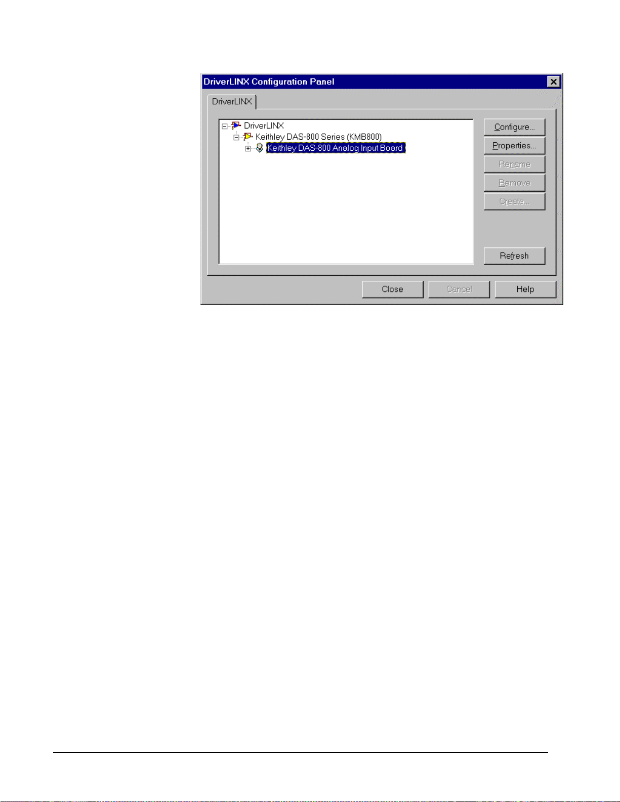
When you click the Configure… button on the DriverLINX Configuration Panel,
DriverLINX displays the Configure DriverLINX Device dialog. The dialog has a
page for each subsystem on a Keithley DAS-800 Series model. The following
sections describe your choices in configuring DriverLINX to work with your board.
12 • Configuring the DAS-800 Series Keithley DAS-800 Series
Page 13

Device Subsystem Page
Use the Device subsystem page to tell DriverLINX the model name, address and,
optionally, the expansion accessories connected to your DAS-800 Series board.
Vendor
The Vendor property displays “Keithley Instruments, Inc.” It is a read-only property.
Device
Windows NT
Windows 95/98
Windows NT
The Device property designates the Logical Device you are configuring. It is a readonly property. To change it, first save (OK) or quit (Cancel) the current
configuration. Then select or create a new Logical Device using the DriverLINX
Configuration Panel.
Model
The Model property selects or indicates the hardware model of the board you’re
configuring.
Select one of the following models:
DAS-800
DAS-801
DAS-802
Under Windows 95/98, DriverLINX displays the model you chose during
installation. To install a different model, cancel the configuration and run Add New
Hardware from the Windows Control Panel.
Address
The Address property records the I/O port address for the board. The default address
used by DriverLINX is 768 decimal or 0x300 hex. If you have another peripheral
board at the same address, select a different base address. Note: you need a block of
eight free addresses.
Keithley DAS-800 Series Configuring the DAS-800 Series • 13
Page 14
Windows 95/98
Under Windows 95/98, Add New Hardware automatically selects an appropriate
address. To change the address, see “Using the Windows 95/98 Device Manager” on
page 15.
Detect
The Detect property enables and disables DriverLINX’s hardware detection and
testing algorithms. For maximum system reliability, always leave this check-box
marked.
Calibrate
The Calibrate property enables and disables hardware auto-calibration. This option is
grayed-out for the DAS-800 Series because it does not support autocalibration.
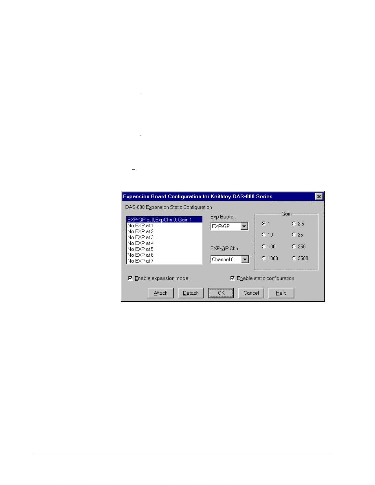
Special…
The Special… button displays the following dialog box of DAS-800 Series-specific
configuration options:
The Expansion Board Configuration for Keithley DAS-800 Series dialog allows you
to enable analog input expansion channels. By enabling analog input expansion
channels, you can run tasks that sample Analog Input Expansion Channels from an
add-on multiplexer. (See Enable expansion mode.)
The Expansion Board Configuration for Keithley DAS-800 Series dialog also allows
you to record the gain selections for each multiplexer attached to an analog input
channel. (See Enable static configuration.)
Note: On models DAS-801 and 802, using a multiplexer requires setting the
associated base channel’s switch to single-ended.
14 • Configuring the DAS-800 Series Keithley DAS-800 Series
Page 15

•
Enable expansion mode
Checking Enable expansion mode allows you to run tasks with Analog Input
Expansion Channels in the task’s Channel/Gain list.
•
Enable static configuration
Checking Enable static configuration allows you to record the gain
selections for each multiplexer attached to the analog input channels.
DriverLINX uses this information to correctly convert A/D codes to
volts. Checking Enable static configuration enables the following
controls, which you will use to record information about your
multiplexers.
•
DAS-800 Expansion Static Configuration
Select the analog input channel that you want to configure. DriverLINX
records gain selections for an expansion accessory attached to each base
channel. To record your Exp Board and Gain setting for the selected
channel, click Attach. To clear previous settings for the selected
channel, click Detach.
•
Exp Board
Select an expansion accessory type in the list. DriverLINX supports the
following expansion accessory types:
EXP-800
EXP-16/16A
EXP-GP
•
EXP-GP Chn
If you selected the EXP-GP from the Exp Board list, select each EXP-GP
channel and record its gain setting. Note: The gains for all channels on
an EXP-GP must be from one of two sets of gains: (1, 10, 100, 1000) or
(2.5, 25, 250, 2500).
•
Gain
Select the gain that matches the settings of your multiplexer’s gain switches.
The gains listed change with your Exp Board selection.
Note: With static configuration disabled, you must perform gain correction in your
application.
Note: You can disable expansion mode and/or static configuration without losing
existing gain settings.
Using the Windows 95/98 Device Manager
Under Windows 95/98, DriverLINX uses the address and interrupt settings
maintained by the Windows Device Manager.
To view or change the settings for your board using the Devi ce Manager:
1. Start the Device Manger by right-clic king on My Computer and
selecting Properties or click here
2. Click the Device Manger tab.
.
3. Click the
list.
Keithley DAS-800 Series Configuring the DAS-800 Series • 15
next to , if necessary to expand the
Page 16

4. Under DriverLINX drivers, select the entry for your board. (It may or
may not have
next to it.)
5. Click the Properties button.
6. On the board’s property page, click the Resources tab.
7. To configure the board with an interrupt, use Setting based on “Basic
configuration 0.” Or, to configure the board without an interrupt, use
Setting based on “Basic configuration 1.”
8. To change a setting, select it under Resource Type and click the Change
Setting button. Windows will guide you in selecting an appropriate
value.
9. When you are done, click OK to close the board’s property page.
10. The board’s a ddress switches must match the address setting you select.
If necessary shut down your computer and reposition them as described
in your hardware manual.
11. Restart Windows to load the Logical Device for your board using the
new settings.
16 • Configuring the DAS-800 Series Keithley DAS-800 Series
Page 17

Analog Input Subsystem Page
Use the Analog Input subsystem page to set or view your board’s interrupt request
level.
Channels
All DAS-800 Series boards have 8 analog input channels. On DAS-801 and 802
models, you can switch each channel to differential or single-ended. The switch
setting affects only the connections for the channel.
DriverLINX grays out this property in the configuration dialog.
Windows NT
Windows 95/98
Range
The analog input ranges for the DAS-800 Series are fully software programmable.
DriverLINX grays out this property in the configuration dialog.
Interrupt
For Windows NT, select a free interrupt request level to support interrupt mode
transfers. Valid IRQ levels are: 2, 3, 4, 5, 6, 7 and None.
Under Windows 95/98, Add New Hard ware automatically selects an appropriate
interrupt. To change the address, see “Using the Windows 95/98 Device Manager”
on page 15.
DMA level
The DAS-800 Series does not use system DMA channels. DriverLINX disables this
property.
Keithley DAS-800 Series Configuring the DAS-800 Series • 17
Page 18

For the DAS-800 Series, there
are no configurable options
on the Digital Input
subsystem page.
Digital Input Subsystem Page
Channels
The Channels prop erty allows you to select a Logical Channel for configuration or
viewing the channel’s range. The DAS-800 Series digital input channels have fixed
configurations.
DriverLINX defines the following Logical Channels for the DAS-800 Series digital
inputs:
Logical Channel DriverLINX Function DAS-800 Series External
Connector
0 Standard Digital Input IP1 … IP3
1 External Tri gger IP1/TRIG
2 External Clock INT_IN/XCLK
Range
The Range property specifies the supported digital input range for the selected
Logical Channel. This is a read-only property.
Interrupt
The DAS-800 Series uses the same interrupt for digital input as for analog input. Go
to the Analog Input page to set it. DriverLINX grays out this property and displays it
as blank.
DMA level
The DAS-800 Series does not use system DMA channels. DriverLINX disables this
property and displays it as blank.
Configuration Setup
The Configuration Setup property specifies the hardware configuration of the digital
I/O ports. The DAS-800 Series has a fixed digital I/O configuration. Therefore,
DriverLINX disables this field.
18 • Configuring the DAS-800 Series Keithley DAS-800 Series
Page 19

Initialize
Checking the Initialize check box instructs DriverLINX to use the Configuration
Setup property to configure the digital I/O ports. The DAS-800 Series has a fixed
digital I/O configuration. Therefore, DriverLINX disables this field.
Keithley DAS-800 Series Configuring the DAS-800 Series • 19
Page 20

Digital Output Subsystem Page
Use the Digital Output subsystem page to change the default digital output port
initialization values.
Channels
The Channels property allows you to select a Logical Channel for initialization or
viewing the channel’s range. DAS-800 Series boards only have a single digital output
channel.
Range
The Range property specifies the supported digital output range for the selected
Logical Channel. This is a read-only property.
Interrupt
The DAS-800 Series uses the same interrupt for digital output as for analog input. Go
to the Analog Input page to set it. DriverLINX grays out this property and displays it
as blank.
DMA level
The DAS-800 Series does not use system DMA channels. DriverLINX disables this
property and displays it as blank.
Initialization Value
The Initialization Value property specifies the digital output value DriverLINX will
write to the selected Logical Channel on hardware initialization. DriverLINX only
writes this value if you enable the Initialize check box. By default, DriverLINX uses
the hardware-defined initialization values if the Initialize check box is not checked.
For the DAS-800 Series, the default digital output value is zero.
Initialize
Checking the Initialize check box instructs DriverLINX to use the Initialization
Value property, rather than the default value, for digital output port initialization.
20 • Configuring the DAS-800 Series Keithley DAS-800 Series
Page 21

Dec
This check box converts the Initialization Value property to decimal.
Hex
This check box converts the Initialization Value property to hexadecimal.
Keithley DAS-800 Series Configuring the DAS-800 Series • 21
Page 22

For the DAS-800 Series, there
are no configurable options
on the Counter/Timer
subsystem page.
Counter/Timer Subsystem Page
Resolution
The Resolution property specifies the clock frequency of the master oscillator. All
models have a 1.0 MHz clock source for pacing I/O and count/timer operations.
Interrupt
The DAS-800 Series does not support interrupts from counter/timers. DriverLINX
disables this property and displays it as blank.
22 • Configuring the DAS-800 Series Keithley DAS-800 Series
Page 23

Using the DAS-800 Series with
DriverLINX
Introduction
This chapter shows you how to set up and use DAS-800 Series hardware features
with DriverLINX. See the Analog I/O Programming Guide for an overview of
DriverLINX programming.
The descriptions here use the Edit Service Request dialogs for language and API
independence. For the correct syntax with the language you’re using, please see the
DriverLINX Technical Reference Manuals. For DriverLINX examples in your
programming language, p lease see the sourc e code examples in the subdirectories of
your DriverLINX installation directory or on the original distribution media.
DriverLINX Hardware Model for DAS-800 Series
DriverLINX provides a portable, hardware-independent API for data-acquisition
boards while still allowing applications to access unique or proprietary hardware
features of specific products. To achieve this goal, DriverLINX maps a hardwareindependent, or abstract, data-acquisition model onto DAS-800 Series hardware
capabilities.
The following sections describe how DriverLINX implements DAS-800 Series
hardware features as Subsystems, Modes, Operations, Events, Logical Channels,
Buffers, and Messages.
DriverLINX Subsystems
The DAS-800 Series supports five of the six of DriverLINX’s subsystems:
1. Device—refers to a DAS-800 model as a whole.
2. Analog Input—refers to the analog input channels, clocks, and control
signals.
3. Analog Output—refers to the analog output channels, clocks, and
control signals. The DAS-800 Series does not support Analog Output.
Keithley DAS-800 Series Using the DAS-800 Series with DriverLINX • 23
Page 24

4. Digital Input—refers to the 4-bit digital input port as well as 1-bit
digital input (TTL) control signals, such as INT_IN/XCLK, etc.
5. Digital Output—refers to the 4-bit digital output port.
6. Counter/Timer—refers to the input/output subsystem-specific internal
clock channels as well as independent counter/timers.
DriverLINX Modes
Applications use modes in Service Requests to advise DriverLINX on their preferred
hardware data transfer technique. The DriverLINX modes fall into two general
classes:
•
Foreground or synchronous modes. The calling application doesn’t
regain control until DriverLINX completes the Service Request.
DriverLINX supports this mode for simple, single value I/O operations
or software housekeeping functions that DriverLINX can complete
without a significant delay.
•
Background or asynchronous modes. The calling application regains
control as soon as DriverLINX initiates the task. The calling application
must synchronize with the data-acquisition task using status polling or
DriverLINX’s messages (preferred). DriverLINX supports this mode
for buffered data transfers or for commands that require a significant
time to complete.
DriverLINX supports three modes with the DAS-800 Series for its commands
(Service Requests).
•
Polled Mode—T his is a foreground or synchronous operation.
DriverLINX supports this mode for simple, single-value I/O operations
that the data-acquisition board can complete without significant delay.
•
Interrupt Mode—Thi s is a background or asynchronous operation.
DriverLINX transfers data between the computer’s memory and the
data-acquisition board using hardware interrupts and programmed I/O
transfers.
•
Other Mode—This is a foreground or synchronous opera tion.
DriverLINX supports this mode for initialization, configuration,
calibration, data conversion, and timebase operations.
The following table summarizes the data acquisition modes that DriverLINX
supports for each subsystem with the Keithley DAS-800 Series.
Subsystem Polled Interrupt DMA Other
Analog Input
Analog Output
Digital Input
Digital Output
Counter/Timer
Device
¥¥ ¥
¥¥ ¥
¥¥ ¥
¥¥
¥
DAS-800 Series Supported DriverLINX Modes.
24 • Using the DAS-800 Series with DriverLINX Keithley DAS-800 Series
Page 25

DriverLINX Operations and Events
Applications construct DriverLINX data-acquisition tasks by combining a small
number of DriverLINX operations and events in many possible ways. The following
table summarizes the operations and events that DriverLINX supports for the
Keithley DAS-800 Series. Later sections for each DriverLINX subsystem will
describe the operations and events in more detail.
Note: All subsystems allow the MESSAGE operation and the Analog Input
subsystem allows the CONVERT operation, which are not shown in the table.
DriverLINX allows any Mode setting for these operations.
Subsystem Operation Events
Mode Timing Start Stop
Analog Input
Polled Start null null, cmd null, TC
Interrupt Start, Stop,
Status
Other Initialize
Digital Input
Polled Start null null, cmd null, cmd, TC
Interrupt Start, Stop,
Status
Other Initialize
rate, dig cmd, dig, ana cmd, TC
rate, dig cmd cmd, TC
Digital Output
Polled Start null null, cmd null, cmd, TC
Interrupt Start, Stop,
Status
Other Initialize
Counter/Timer
Polled Start, Stop,
Status
Other Initialize,
Configure
Device
Other Initialize,
Configure,
Capabilities
Allowed Operations and Events for DAS-800 Series Subsystems and Modes.
rate, dig cmd cmd, TC
null, rate null, cmd null, cmd, TC
CT Setup
The following list explains the Event abbreviations in the preceding table:
•
null—Null or None Event when a Service Request doesn’t require an
event
•
cmd—Command Event when DriverLINX starts or stops a task on
software command
Keithley DAS-800 Series Using the DAS-800 Series with DriverLINX • 25
Page 26

•
TC—Terminal Count Event when DriverLINX processes all data
buffers once
•
rate—Rate Event specifies how DriverLINX paces or clocks data
transfer
•
dig—Digital Event specifies a trigger, clock, or other control signal to
pace, start, or stop a task
•
ana—Analog Event specifies an analog input signal to pace, start, or
stop a task
Logical Channels
DriverLINX designates the individually addressable hardware channels for each
subsystem as “Logical Channels.” Generally, the zero-based Logical Channel
numbering sequence closely follows the hardware manufacturer’s cha nnel numbering
scheme.
In some cases, however, DriverLINX assigns Logical Channel numbers to hardware
features that users don’t commonly think of as “channels.” For instance, DriverLINX
commonly models external hardware clock input lines, external hardware trigger
input lines, and external interrupt inputs as 1-bit digital Logical Channels. In other
cases, DriverLINX models subsystem-specific features, such as internal pacer clocks,
as members of a more general purpose set of counter/timer channels.
For a list of DriverLINX assigned Logical Channel numbers, see the notes on each
supported subsystem.
Buffers
Applications usually use data buffers to exchange data between the application and
the data-acquisition hardware. When using data buffers, please note the following
points about DriverLINX’s data buffers:
•
DriverLINX supports data-acquisition tasks with 1 to 255 data buffers
per task.
•
DriverLINX i mposes no size limits o n a single buffer, alt hough the
operating system or some hardware products may have size restrictions.
•
User applications must allow DriverLINX to allocate all data buffers to
guarantee application portability to different hardware and operating
systems and to insure that the hardware can physically access the buffer
memory.
•
User applications usually don’t have concurrent or immediate access to
the in-use data buffer while DriverLINX is executing a data-acquisition
task.
26 • Using the DAS-800 Series with DriverLINX Keithley DAS-800 Series
Page 27

Connecting Signals to the DAS-800 Series
The Keithley hardware manual describes the data and control signals for the DAS800 Series and the connector pinouts for these signals. This section summarizes how
DriverLINX numbers the I/O data signals and how DriverLINX uses several of these
control connections for ext ernal clock, trigger, and gating inputs.
Analog Input Subsystem Signals
The Analog Input subsystem has 8 analog input single-ended or differential signal
connections depending on the model of your DAS-800 board. DriverLINX maps
these signals to Logical Channels as shown in the following table:
A/D Channels Connector Name Logical Channels
Channel 0-7 DAS-800 IN0 – IN7/LLCOM 0–7
Channel 0-7 DAS-801/802 IN0+/IN0- – IN7+/IN7- 0–7
How DriverLINX maps analog input hardware channels to Logical Channels.
Analog Input Pacing, Trigger ing and Gating Signals
Analog input tasks can use the internal pacer clock, which DriverLINX designates as
Counter/Timer Logical Channels 2 (single) or 3 (cascaded). Analog input tasks can
also use an external pacer clock, which DriverLINX designates as Counter/Timer
Logical Channel 5.
The Analog Input subsystem uses two control signals that DriverLINX defines as
external clocks, gates, and triggers as shown in the following table:
Connector Name DriverLINX Usage
INP1/TRIG External trigger/External Gate
INT_IN/XCLK External pacer clock
How DriverLINX uses analog input control signals.
Keithley DAS-800 Series Using the DAS-800 Series with DriverLINX • 27
Page 28
Digital Input Subsystem Signals
The Digital Input subsystem has one 3-bit digital input port and two control inputs
which DriverLINX models as 1-bit logical digital input ports. DriverLINX maps
these signals to Logical Channels as shown in the following table:
Port Connector Name Logical Channels
3-bit digital input INP0 … INP2 0
External trigger alias INP1/TRIG 1
External clock alias INT_IN/XCLK 2
How DriverLINX maps digital input hardware channels to Logical Channels.
Digital Input Pacing Signals
Digital input tasks can use the internal pacer clock, which DriverLINX designates as
Counter/Timer Logical Channels 2 (single) or 3 (cascaded). Digital input tasks can
also use an external pacer clock, which DriverLINX designates as Counter/Timer
Logical Channel 5.
Digital Output Subsystem Signals
The Digital Output subsystem has one 4-bit digital output port. DriverLINX maps
these signals to Logical Channels as shown in the following table:
Port Connector Name Logical Channels
4-bit digital output OP0 … OP3 0
How DriverLINX maps digital output hardware channels to Logical Channels.
Digital Output Pacing Signals
Digital output tasks can use the internal pacer clock, which DriverLINX designates as
Counter/Timer Logical Channels 2 (single) or 3 (cascaded). Digital output tasks can
also use an external pacer clock, which DriverLINX designates as Counter/Timer
Logical Channel 5.
28 • Using the DAS-800 Series with DriverLINX Keithley DAS-800 Series
Page 29

Counter/Timer Subsystem Signals
The Counter/Timer subsystem has several internal and external hardware timers. The
DAS-800 Series boards have three sixteen-bit timers and an external clock input. The
three timers can operate independently or in combination. DriverLINX maps these
internal and external timers to Logical Channels as shown in the following table:
Timer Connector Name Logical Channels
C/T 0 CLK 0, GATE 0, O UT 0 0
C/T 1 CLK 1, GATE 1, O UT 1 1
C/T 2 GATE 2*, IP1/TRIG*,
OUT 2
C/T 1 & C/T 2 GATE 2*, IP1/TRIG*,
OUT 1
C/T 0 & C/T 2** GATE 2, OUT 0 4
External Clock INT_IN/XCLK, IP1/TRIG 5
How DriverLINX maps counter/timer hardware channels to Logical Channels.
* The DAS-800 Series uses the IP1/TRIG signal to gate input/output tasks and the
GATE 2 signal to gate counter/timer tasks on Logical Channels 2 and 3.
** To use C/T 0 & C/T 2 together, make an external connection between OUT 2 and
CLK 0.
2
3
Keithley DAS-800 Series Using the DAS-800 Series with DriverLINX • 29
Page 30

Device Subsystem
The following sections describe how DriverLINX implements Device Subsystem
features for the DAS-800 Series.
Device Modes
The Device Subsystem only supports DriverLINX’s Other mode for all operations.
Device Operations
The DAS-800 Series Device Subsystem supports the following DriverLINX
operations:
If another application is using
the same data-acquisition
board, DriverLINX will
prevent Device Initialization
from interfering with another
application’s data-acquisition
tasks.
•
Initialize—DriverLINX aborts all data-acquisition tasks for every
subsystem controlled by the current application. DriverLINX then
performs an initialization for each supported subsystem.
•
Configure—DriverLINX displays the Configure DriverLINX Device
dialog for the current Logical Device. Please use the DriverLINX
Configuration Panel rather than this operation to configure
DriverLINX.
•
Capabilities—DriverLINX provides hardware-specific and
configuration information in the form of a Logical Device Descriptor
database.
30 • Using the DAS-800 Series with DriverLINX Keithley DAS-800 Series
Page 31

Analog Input Subsystem
The following sections describe how DriverLINX implements Analog Input
Subsystem features for the DAS-800 Series.
Analog Input Modes
The Analog Input Subsystem supports the following modes:
•
Polled—For single value analog input samples.
•
Interrupt—For buffered transfers using programmed I/O.
•
Other—For subsystem initialization and data conversion.
Analog Input Operations
The DAS-800 Series Analog Input Subsystem supports the following DriverLINX
operations:
•
Initialize—aborts all active analog input data-acquisition tasks.
However, DriverLINX prevents one application from interfering with
another application’s data-acquisition tasks.
•
Start—initiates a data-acquisition task using the Mode, Timing, Start,
and Stop Events, the Logical Channels, and the Buffers the application
specified in the Service Request.
•
Status—reports the buffer position of the next sample that DriverLINX
will write into a buffer.
•
Stop—terminates an analog input data-acquisition task.
•
Message—DriverLINX displays a pop-up dialog box for the user
containing the text for the current DriverLINX error message.
Analog Input Timing Events
Timing Events specify how the hardware paces or clocks the acquisition of analog
input samples. DriverLINX uses the Timing Event to program when the DAS-800
Series acquires the next analog input sample.
The DAS-800 Series supports the following Timing Events:
•
None—Sampling requires no pacing as DriverLINX is acquiring only a
single value.
•
Rate—The DAS-800 Series supports fixed rate sampling using internal
and external clocks.
•
Digital—DriverLINX uses an external digital input signal to pace the
acquisition of the next sample.
None or Null Event
The Null Event specifies that the task does not need a clock to determine when to
acquire the next sample.
Keithley DAS-800 Series Using the DAS-800 Series with DriverLINX • 31
Page 32

Rate Event
The DAS-800 Series supports a single Rate Event for analog input:
•
Rate Generator—Generates a fixed rate clock with equal time
intervals between tics.
Rate Generator: Internal Clocking
An internally clocked Rate Generator produces a fixed rate clock with equal time
intervals between tics.
Period
Use an internally clocked rate generator when you want to acquire all analog input
samples at equally spaced time intervals.
How to set up the DAS-800 Series for fixed rate sampling using an internal clock.
For hardware independence,
specify the clock channel
using the symbolic constant,
DEFAULTTIMER, which
always maps to the default
Logical Channel for analog
input timing.
•
Specify internal cl ocking using a Rate Generator on Channel 2 or 3
with the Internal 1 Clock source. See “Counter/Timer Subsystem” on
page 63 for a description of clock sources.
•
The Period property specifies the time interval between samples in tics,
where an Internal 1 tic is 1 µs, or 1 MHz. The minimum period is 25
tics, or 40 kHz. The maximum period is 4294967295 tics (
32
21
− ), or
0.000233 Hz.
32 • Using the DAS-800 Series with DriverLINX Keithley DAS-800 Series
Page 33
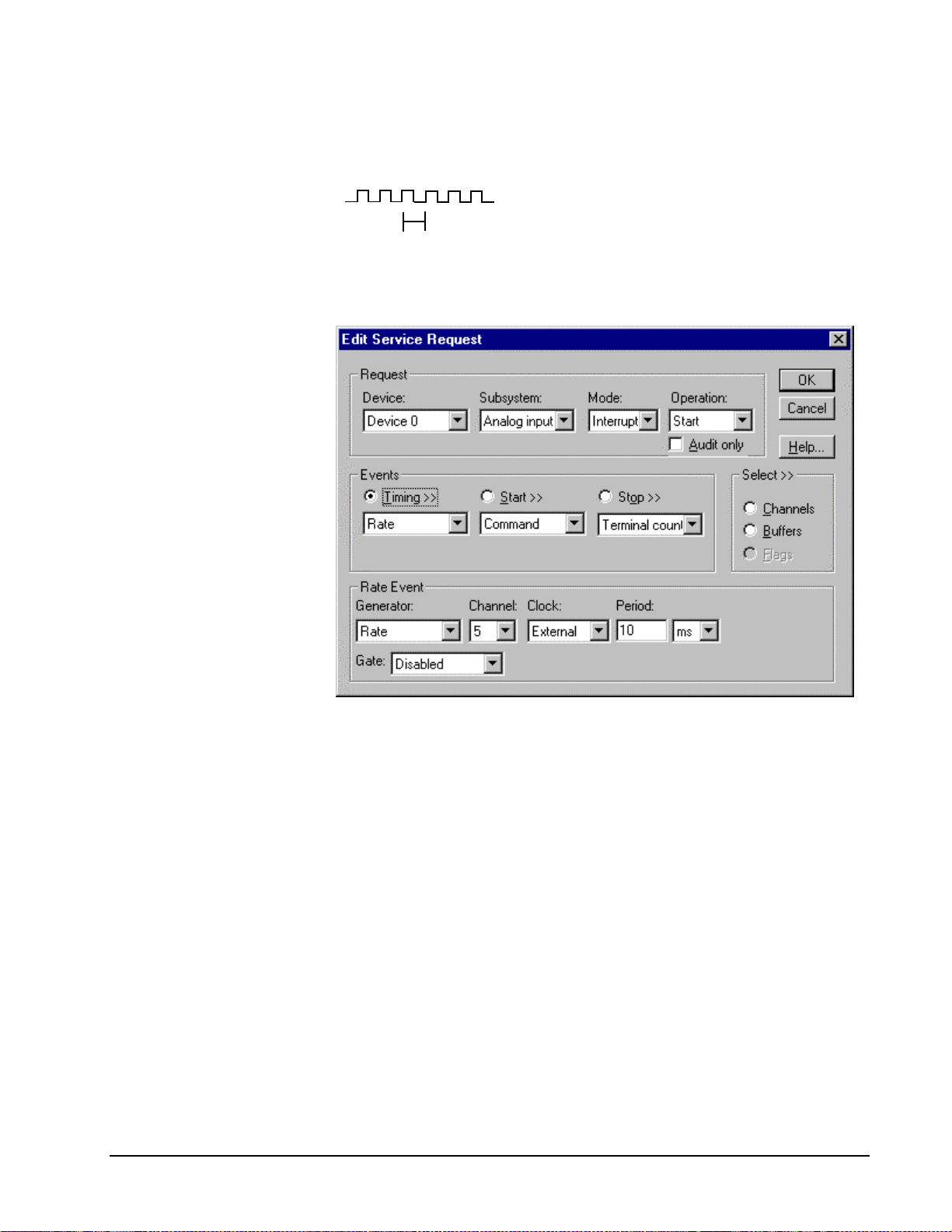
Rate Generator: External Clocki ng
An externally clocke d Rate Generator produces a rate clock with unknown time
intervals between tics.
Period (ext clk)
Use an externally clocked rate generator when you want to synchronize analog input
samples with a recurrent external signal. In this mode you will need a separate
external clock tic for each analog sample you want to acquire.
BE SURE that the external
clock source is TTL
compatible, 0 V minimum to
+5 V maximum!
How to set up the DAS-800 Series for fixed rate sampling using an external clock.
•
Specify external clocking using a Rate Generator on Channel 5 with
an External, or External- Clock source. See “Counter/Timer
Subsystem” on page 63 for a description of clock sources.
•
Users should connect the external clock signal to the INT_IN/XCLK
line.
•
The Period may be any va lue ≥ 50 tics, or 10 µs. The period value
doesn’t affect the external clock frequency, but DriverLINX requires a
valid hardware value in case the application requests a timebase
operation and to optimize data transfer between the driver and the
application.
•
The frequency of the external clock must not exceed 40 kHz.
Keithley DAS-800 Series Using the DAS-800 Series with DriverLINX • 33
Page 34

Digital Event
DriverLINX supports Digital Events as aliases for externally clocked Rate
Generators. Use this technique for compatibility with data-acquisition products that
only support external clock sources.
How to set up the DAS-800 Series for external rate sampling using a digital event.
•
Specify external cl ocking using Channel 2. For hardware-
independence, you can specify the hardware external trigger channel by
the symbolic constant, DI_EXTCLK.
•
Users should connect the external clock signal to the INT_IN/XCLK
line.
•
Specify the Mask property as 1, or Bit 0, to indicate that DriverLINX
should only compare a 1-bit digital input value against the Pattern
property.
•
Specify the Match property as Not equals.
•
Specify the Pattern property as 1 for a falling, or negative , edge clock
(≠1).
Analog Input Start Events
Start Events specify when the DAS-800 hardware starts acquiring analog input data.
The DAS-800 Series supports the following Start Events:
•
None—Use this event when the DriverLINX operation does not require
a Start Event.
•
Command—DriverLINX starts the task on software command, i.e., as
soon as DriverLINX finishes programming the DAS-800 hardware for
the task.
34 • Using the DAS-800 Series with DriverLINX Keithley DAS-800 Series
Page 35

•
Digital—The DAS-800 starts acquiring analog input samples when the
hardware detects the digital Logical Channel input satisfies the
condition specified in the Start Event.
•
Analog—The DAS-800 starts acquiring analog input samples when the
hardware detects the analog Logical Channel input satisfies the
condition specified in the Start Event.
None or Null Event
The Null Event specifies that the task does not need a Start Event to begin the task.
Command Event
The Command Event starts data acquisition as soon as DriverLINX has completed
programming the data-acquisition hardware with the task parameters.
Digital Event or Post Triggering
The DAS-800 can acquire analog input samples after the hardware detects a digital
trigger condition. Use post-triggering when you want to synchronize the start of data
acquisition with an external signal.
How to set up the DAS-800 Series for post-triggered analog input.
Digital Start Events contain mask, pattern, and match fields. The mask is logically
ANDed with the digital input data on the Logical Channel and then compared with
the pattern for a match/mismatch.
•
Specify the Channel as 1. For hardware-independence, you can specify
the hardware external trigger channel by the symbolic constant,
DI_EXTTRG.
•
Users should connect the external trigger signal to the INP1/TRIG line.
Keithley DAS-800 Series Using the DAS-800 Series with DriverLINX • 35
Page 36

•
Specify the Mask property as 1, or Bit 0, to indicate that DriverLINX
should only compare a 1-bit digital input value against the Pattern
property.
•
Specify the Match property as Not equals.
•
Specify the Pattern property as 0 for a rising, or positive, edge trigger
(≠0).
32
21
•
Specify the Delay property as any integer from 0 to
− .
DriverLINX discards this number of samples after the trigger.
Analog Event or Post-Triggering
The DAS-800 can acquire analog input samples after the hardware detects an analog
trigger condition. Use post-triggering when you want to synchronize the start of data
acquisition with an external signal.
How to set up the DAS-800 Series for post-triggered analog input.
Analog Start Events contain Channel, Gain, Polarity and Limit fields. The limits
determine the type of analog event (Level, Edge, Limit, Band). DriverLINX samples
data from the Logical Channel and compares it against the High and Low Limits. The
trigger occurs when a sequence of samples is in the relationship specified by Polarity
and Limits.
•
Specify the Channel from the analog input subsystem. For the DAS-800
Series, the analog event channel must be a channel in scan list.
•
Specify the Gain property for the analog event channel.
•
Specify the Polarity (or Slope) property as Pos or Neg. For a Level
event, Pos means the trigger occurs when a sample is above the (high)
threshold. For a Limit event, Pos means the occurs when a sample is
between the limits.
•
Specify the Limit properties in hardware A/D codes as follows:
36 • Using the DAS-800 Series with DriverLINX Keithley DAS-800 Series
Page 37

Type High Limit Low Limit
Level, above Maximum AI code Threshold
Level, below Threshold Minimum AI code
Limits, inside or outside Upper Threshold Lower Threshold
Edge, positive or negative
crossing
Band, positive or negative
crossing
Threshold Threshold
Upper Threshold Lower Threshold
Use the DriverLINX Volts2Code method to easily convert volts to
hardware A/D codes for the threshold properties.
•
Specify the Delay property as any integer from 0 to
32
21
− .
DriverLINX discards this number of samples after the trigger.
Analog Input Stop Events
Stop Events specify when the hardware stops acquiring analog input data.
The DAS-800 Series supports the following Stop Events:
•
None—Use this event when the DriverLINX operation doesn’t require
a Stop Event.
•
Command—Dr iverLINX stops the task on software command, i.e.,
when the application issues a Service Request with a Stop operation.
•
Terminal count—DriverLINX stops the task after the data-acquisition
hardware has filled all the data buffers once.
None or Null Event
The Null Event specifies that the task does not need a Stop Event to end the task.
Command Event
The Command Event stops data acquisition when the user application changes the
Operation property in the Service Request to Stop and resubmits the Service Request
to DriverLINX.
In Stop-on-Command mode , DriverLINX continuously cycles through al l the data
buffers filling them with analog input data from the data-acquisition hardware.
Terminal Count Event
The Terminal Count Event stops data acquisition after DriverLINX has filled all the
data buffers once with analog input data. Use Terminal Count when you want to
acquire a single scan or fixed amount of data.
Keithley DAS-800 Series Using the DAS-800 Series with DriverLINX • 37
Page 38

Analog Input Channels
The DriverLINX allows applications to specify analog input channels using three
techniques:
•
Start Channel—Acquire data from a single channel.
•
Start/Stop Channel Range—Acquire data from a consecutive range of
channels.
•
Channel List—Acquire data from a list of channels.
The DAS-800 Series models support a variety of channel gains. The DAS-800 has a
fixed bipolar range (-5 to +5 V). The DAS-801 and 802 have five programmable
bipolar gains and four programmable unipolar gains.
The following tables show the correspondence between DriverLINX gains, the
maximum input signal range, and the hardware gain code for each input range. Note:
DriverLINX uses a negative (-) gain value to signify a bipolar (±) range.
DAS-800
Gain Range (volts) Hardware Gain Code
-1 ±5 0
Gains, Ranges, and DriverLINX Gain Codes for Model DAS-800.
DAS-801
Gain Range (volts) Hardware Gain Code
-1 ±5 0
-0.5 ±10 1
1 0 … 10 2
-10 ±0.5 3
10 0 … 1 4
-100 ±0.05 5
100 0 … 0.1 6
-500 ±0.01 7
500 0 … 0.02 8
Gains, Ranges, and DriverLINX Gain Codes for Model DAS-801.
38 • Using the DAS-800 Series with DriverLINX Keithley DAS-800 Series
Page 39

DAS-802
Gain Range (volts) Hardware Gain Code
-1 ±5 0
-0.5 ±10 1
1 0 … 10 2
-2 ±2.5 3
20 … 54
-4 ±1.25 5
40 … 2.56
-8 ±0.00625 7
8 0 … 1.25 8
Gains, Ranges, and Gain Codes for Model DAS-802.
Use the DriverLINX Gain2Code method to easily convert between the gains in the
above tables and hardware Gain Codes.
The available gains for an expansion channel are the products of the expansion
board’s gain, set by jumpers, and the programmable gains of the DAS board.
For example, the gains available for a channel on an EXP-16, jumpered for a gain of
10 and attached to a DAS-802, are: -10, -5, 10, -20, 20, -40, 40, 80 and -80.
See “Special…” on page 14 for information on configuring expansion accessories or
"Analog Input Expansion Channels" on page 42 for information on selecting
expansion channel s .
Single Channel Analog Input
In single channel mode, the DAS-800 Series acquires all data from one channel at the
specified gain.
How to set up the DAS-800 Series for sampling on a single channel.
Keithley DAS-800 Series Using the DAS-800 Series with DriverLINX • 39
Page 40

Multi-channel Analog Input Range
In multi-channel range mode, the DAS-800 Series acquires data from a consecutive
range of analog channels.
•
The Start Channel and Stop Channel gains must be the same as the
DAS-800 Series does not support changing gains while acquiring a
channel range.
•
If the Start Channel is greater than the Stop Channel, the channel
sequence is [Start Channel, …, 7, 0, …, Stop Channel].
How to set up the DAS-800 Series for sampling on a consecutive range of channels.
40 • Using the DAS-800 Series with DriverLINX Keithley DAS-800 Series
Page 41
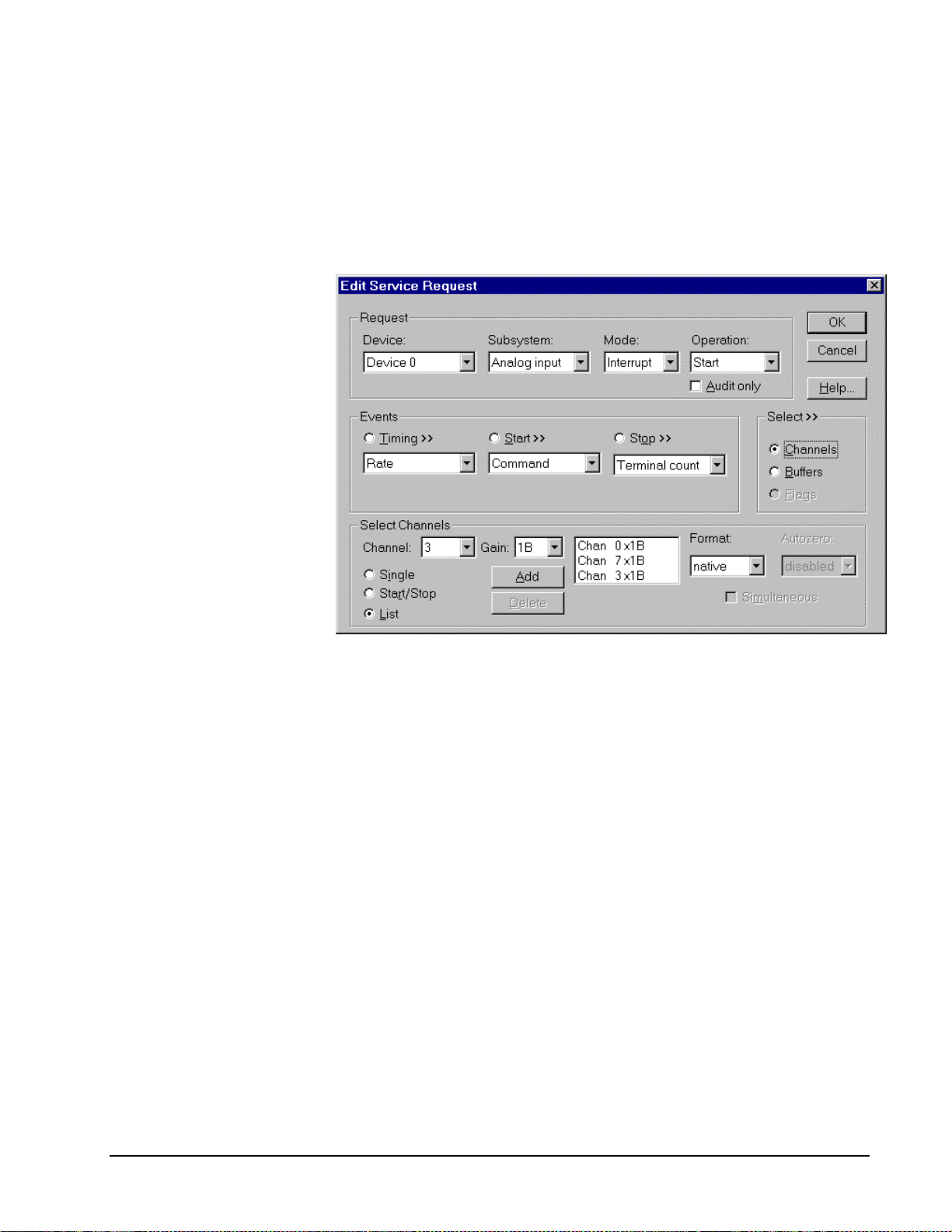
Multi-channel Analog Input List
In multi-channel list mode, the DAS-800 Series acquires data from a random list of
analog channels.
•
The channel-gain list may contain up to 256 channels in any order and
with any supported gain. The list may repeat a channel with the same or
different gains. See “Using a Channel/Gai n List on the DAS-800
Series” below for special considerations when using a channel-gain list.
How to set up the DAS-800 Series to sample on a random list of channels.
Using a Channel/Gain List on the DAS-800 Series
The DAS-800 hardware supports sampling only a single channel or a consecutive
range of channels at constant gain. DriverLINX simulates a hardware channel/gain
list for the DAS-800 in software by changing the board’s channel, gain, and
expansion multiplexer settings during an interrupt service routine.
When DriverLINX reprograms the DAS-800 with the next entry in the channel-gain
list, the hardware needs a minimum settling time for the multiplexers and
programmable gain amplifiers to acquire the signal on the new channel and/or at the
new gain. Due to the wide statistical distribution of interrupt latencies in a non-real
time operating system, software reprogramming of the DAS-800 hardware may occur
too late to satisfy the hardware’s minimum settling time before the start of the next
A/D conversion cycle.
DriverLINX’s software channel-gain list reprogramming algorithm can insure the
DAS-800 hardware’s minimum settling time requirements are satisfied only if the
data-acquisition task satisfies two requirements.
1. The task must use an internal clock. When an application uses an
external clock, DriverLINX cannot measure the time interval to the next
clock pulse which starts A/D conversion to insure minimum settling
time.
Keithley DAS-800 Series Using the DAS-800 Series with DriverLINX • 41
Page 42

2. The channel-gain list gain entries do not contain a gain of 500. At a
gain of 500, the DAS-800 settling and conversion times increase. See
below for a technique to compensate for the longer settling time at a
gain of 500.
If the task satisfies the above restrictions, DriverLINX will detect when the operating
system called the interrupt service routine too late to meet the minimum settling time
specification. In this situation, DriverLINX will report a “data lost” message to the
application and terminate the task. The maximum sustainable data-acquisition rate
will depend on the speed of the host computer and the peak CPU utilization caused
by all processes and threads running on the host computer.
If the task does not satisfy the above restrictions, sampling using a channel-gain list
may have the following effects:
•
The hardware acquires a sample from the wrong channel due to
insufficient settling time of a channel or expansion multiplexer.
•
The hardware acquires an inaccurate sample value due to insufficient
settling time of a programmable gain amplifier.
You can significantly reduce, but not eliminate, the probability of incorrect channels
or inaccurate values by using the following techniques:
•
Acquire data at slower sampling rates. Slower rates allow more time for
the software to reprogram the hardware for the next channel. Use an
internal clock to empirically determine the maximum sustainable
sampling rate on your computer and limit sampling rates accordingly.
•
Run your application in the foreground and do not start other
applications. This reduces the probability of an occasional occurrence
of an unusually long interrupt latency.
•
Avoid high gain settings. The DAS-800 Series’ programmable gain
amplifier settles faster at lower gains. If the channel-gain list uses a gain
of 500 with an internal clock, sample the channel with a gain of 500
twice and ignore the first value. Repeat this double-sampling technique
with the entry in the channel-gain list that follows a channel with a gain
of 500.
•
Minimize interrupts from other devices during data-acquisition.
For maximum data throughput when sampling multiple channels, scan consecutive
channels at const ant gain rather than using a random, varia ble-gain channel list .
Analog Input Expansion Channels
Multiplexers can expand the number of analog input channels from the 8 base
channels up to 128 differential analog input channels. The DAS-800 Series hardware
automatically switches the multiplexer channels, allowing you to specify expansion
channels along with base channels in a channel list.
To enable DriverLINX to use multiplexers, enable expansion mode in the Expansion
Board Configuration for Keithley DAS-800 Series dialog (see “Special…” on page
14). With expansion mode enabled, DriverLINX considers the board to have the
original 8 base channels followed by 128 expansion channels.
DriverLINX uses a static numbering scheme for attaching multiplexers. Attaching or
removing a mux from a base channel doesn’t cha nge the Logical Channel number of
42 • Using the DAS-800 Series with DriverLINX Keithley DAS-800 Series
Page 43

any other channel. DriverLINX r eserves a fixed numbe r of expansion cha nnels for
each potential mux, whether it is attached or not.
To determine the DriverLINX Logical Channel number for a multiplexer channel,
use the following formula or refer to the table that follows it. Note that DriverLINX
uses 0-based numbering for all channels .
<logical chan#> = <num base chan> + <base chan#> × <num mux chan> + <mux chan#>
Term Description
<logical chan#> Logical Channel number to use in channel lists.
<num base chan> Number of base channels on the DAS-800 board. All DAS-800
models have 8 base channels.
<base chan#> Base channel on the DAS-800 board where you attached the mux.
<num mux chan> Number of expansion channels DriverLINX reserves for the mux.
(16 for DAS-800 expansion accessories).
<mux chan#> Channel on the expansion board where you attached the signal.
Mux channels are numbered from 0 to 15.
For example, the Logical Channel address for channel 4 on a mux attached to base
channel 3 is
8 + 3 × 16 + 4 = 60.
To specify multiplexer input channels 0, 1, and 2 on an expansion board connected to
base channel 0, add 8, 9, and 10 to the channel/gain list.
Keithley DAS-800 Series Using the DAS-800 Series with DriverLINX • 43
Page 44

Mux Base Chan #
Input
Chan
#
0
1
2
3
4
5
6
7
8
9
10
11
01234567
8 2440567288104120
9 2541577389105121
10 26 42 58 74 90 106 122
11 27 43 59 75 91 107 123
12 28 44 60 76 92 108 124
13 29 45 61 77 93 109 125
14 30 46 62 78 94 110 126
15 31 47 63 79 95 111 127
16 32 48 64 80 96 112 128
17 33 49 65 81 97 113 129
18 34 50 66 82 98 114 130
19 35 51 67 83 99 115 131
12
13
14
15
20 36 52 68 84 100 116 132
21 37 53 69 85 101 117 133
22 38 54 70 86 102 118 134
23 39 55 71 87 103 119 135
Table of logical channel numbers for DAS-800 expansion boards.
44 • Using the DAS-800 Series with DriverLINX Keithley DAS-800 Series
Page 45
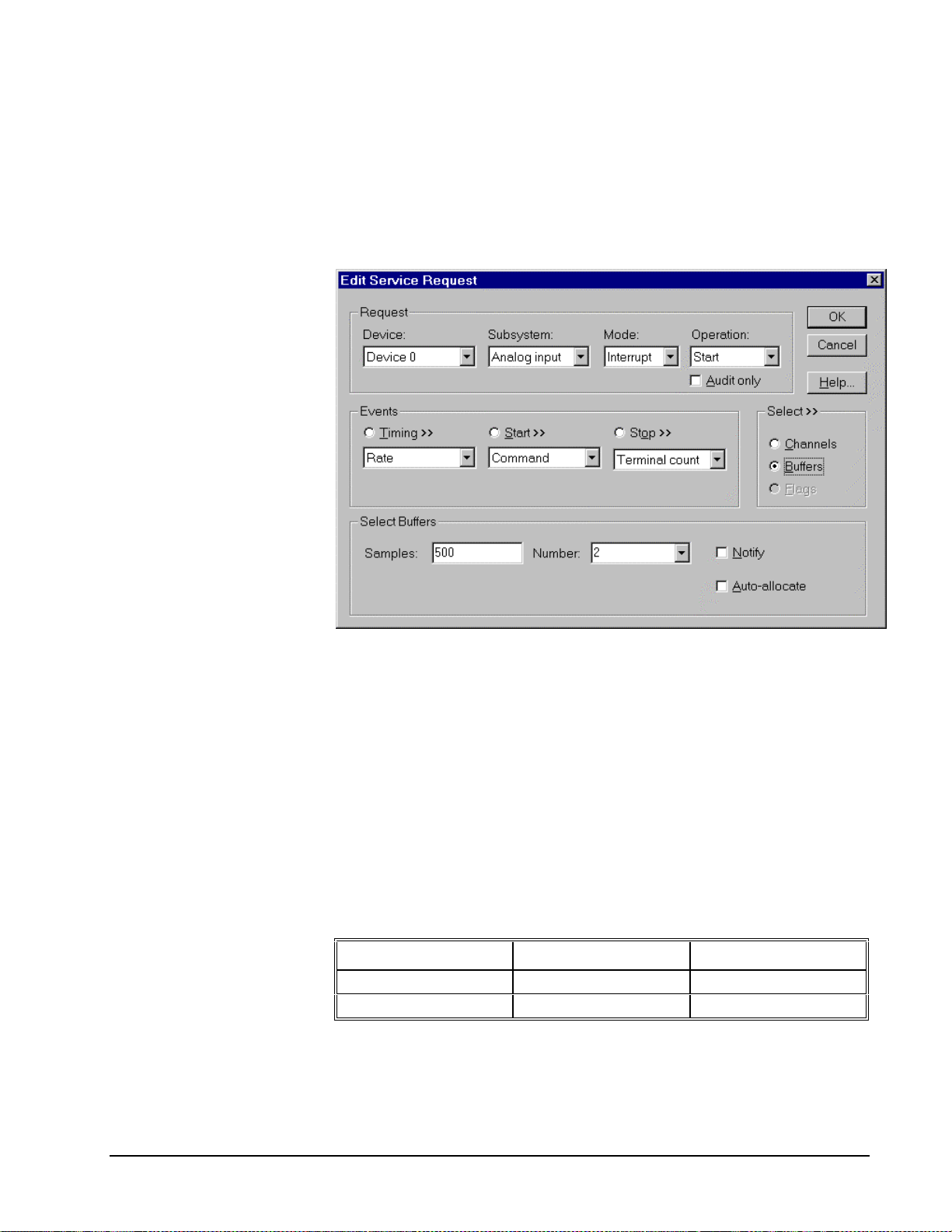
Analog Input Buffers
DriverLINX supports both single-value analog input and buffered analog input.
•
For single-value input, specify the Number of buffers as 0 and the
number of Samples as 1.
•
For buffered input, specify the Number of buffers from 1 to 256 and
the number of Samples as desired.
For example, 500 samples/2
channels = 250 is ok, but 500
samples/3 channels = 166.67
is incorrect.
How to set up the DAS-800 Series to store samples in buffers.
An individual DriverLINX buffer may have any size as long as the buffer length
holds an integral number of channel scans (i.e., a multiple of the number of analog
input channels you’re acquiring). This restriction enforces the requirement that all
acquired channels have the same number of sample s.
Analog Input Data Coding
DAS-800 Series models return A/D hardware codes using binary integers for
unipolar ranges and offset binary for bipolar ranges. DriverLINX refers to this coding
scheme as the “native” format.
For any programmable gain, the DAS-800 models return hardware codes with the
ranges in the following table:
A/D Resolution Polarity A/D Hardware Code
12 bits Unipolar 0 to 4095
12 bits Bipolar -2048 to 2047
Native A/D hardware codes for each DAS-800 Series polarity.
Keithley DAS-800 Series Using the DAS-800 Series with DriverLINX • 45
Page 46

6
4
2
0
-2048 2047
-2
-4
-6
10
8
Bipolar
6
4
2
0
0 4095
Unipolar
DAS-800 Series native A/D Codes versus Voltage Range
DriverLINX refers to the default hardware analog coding scheme as the “native”
format. For computer arithmetic in a higher level language, the integer, or two’s
complement, format is generally easier to use. For unipolar data, native and integer
formats are identical.
For bipolar data, DriverLINX automatically converts A/D codes to integer format, if
you specify integer for the Format property. Or, applications can use DriverLINX’s
data conversion operations to transform an entire data buffer from native format to
many common integer and floating-point formats.
46 • Using the DAS-800 Series with DriverLINX Keithley DAS-800 Series
Page 47

Analog Input Messages
For analog input operations, DriverLINX can report the following messages to the
application:
DriverLINX Message Explanation
Service Start DriverLINX has started the acquisition task.
Service Done DriverLINX has completed the acquisition task.
Buffer Filled DriverLINX has filled an analog input buffer.
Start Event DriverLINX has processed the interrupt for a hard ware start
event.
Data Lost DriverLINX has detected an analog input data overrun
condition.
Critical Error DriverLINX has encountered an unexpected hardware or
software condition.
DriverLINX Event messages for analog input.
Keithley DAS-800 Series Using the DAS-800 Series with DriverLINX • 47
Page 48

Digital Input Subsystem
The following sections describe how DriverLINX implements Digital Input
Subsystem features for the DAS-800 Series.
Digital Input Modes
The Digital Input Subsystem supports the following modes:
•
Polled—For single value digital input samples.
•
Interrupt—For buffered transfers using programmed I/O.
•
Other—For subsystem initialization and data conversion.
Digital Input Operations
The DAS-800 Series Digital Input Subsystem supports the following DriverLINX
operations:
•
Initialize—aborts any active interrupt data-acquisition tasks and stops
•
Start—initiates a data-acquisition task using the Mode, Timing, Start,
the clock. DriverLINX prevents one application from interfering with
another application’s data-acquisition tasks.
and Stop Events, the Logical Channels, and the Buffers the application
specified in the Service Request.
•
Status—reports the buffer position of the next sample that DriverLINX
will read into a buffer.
•
Stop—terminates a digital input data-acquisition task.
•
Message—DriverLINX displays a pop-up dialog box for the user
containing the text for the current DriverLINX error message.
Digital Port Configuration
The DAS-800 Series has separate, dedicated digital input and output ports and
doesn’t require the application to configure its digital I/O ports.
Digital Input Timing Events
Timing Events specify how the hardware paces or clocks the reading of Digital Input
samples. DriverLINX uses the Timing Event to program when the DAS-800 Series
reads the next digital input sample from the port.
The DAS-800 Series supports the following Timing Events:
•
None—Input requires no pacing as DriverLINX i s reading only a single
value.
•
Rate—The DAS-800 Series supports only fixed rate digital input using
an internal hardware clock.
•
Digital—DriverLINX uses an external digital input signal to pace the
acquisition of the next sample.
48 • Using the DAS-800 Series with DriverLINX Keithley DAS-800 Series
Page 49

None or Null Event
The Null Event specifies that the task does not need a clock to determine when to
read the next sample.
Rate Event
The DAS-800 Series supports one type of Rate Event for digital input:
•
Rate Generator—Generates a fixed rate clock with equal time
intervals between tics.
Rate Generator: Internal Clocking
An internally clocked Rate Generator produces a fixed rate clock with equal time
intervals between tics.
Period
How to set up the DAS-800 Series for fixed rate sampling using an internal clock.
For hardware independence,
specify the clock channel
using the symbolic constant,
DEFAULTTIMER, which
always maps to the default
Logical Channel for digital
input timing.
Keithley DAS-800 Series Using the DAS-800 Series with DriverLINX • 49
•
Specify internal cl ocking using a Rate Generator on Channel 2 or 3
with the Internal 1 Clock source. See “Counter/Timer Subsystem” on
page 63 for a description of clock sources.
•
The Period property specifies the time interval between samples in tics,
where an Internal 1 tic is 1 µs, or 1 MHz. The minimum period is 25
tics, or 40 kHz. The maximum period is 4294967295 tics (
0.000233 Hz.
32
21
− ), or
Page 50

Rate Generator: External Clocki ng
An externally clocke d Rate Generator produces a rate clock with unknown time
intervals between tics.
Period (ext clk)
Use an externally clocked rate generator when you want to synchronize digital input
samples with a recurrent external signal. In this mode, you will need a separate
external clock tic for each digital sample you want to acquire.
How to set up the DAS-800 Series for fixed rate sampling using an external clock.
BE SURE that the external
clock source is TTL
compatible, 0 V minimum to
+5 V maximum!
50 • Using the DAS-800 Series with DriverLINX Keithley DAS-800 Series
•
Specify external clocking using a Rate Generator on Channel 5 with
an External, or External- Clock source. See “Counter/Timer
Subsystem” on page 63 for a description of clock sources.
•
Users should connect the external clock signal to the INT_IN/XCLK
line.
•
The Period may be any va lue ≥ 50 tics, or 10 µs. The period value
doesn’t affect the external clock frequency, but DriverLINX requires a
valid hardware value in case the application requests a timebase
operation and to optimize data transfer between the driver and the
application.
Page 51

Digital Event
DriverLINX supports Digital Events as aliases for externally clocked Rate
Generators. Use this technique for compatibility with data-acquisition products that
only support external clock sources.
How to set up the DAS-800 Series for external rate sampling using a digital event.
•
Specify external clocking using Channel 2. For hardware-
independence, you can specify the hardware external trigger channel by
the symbolic constant, DI_EXTCLK.
•
Users should connect the external clock signal to the INT_IN/XCLK
line.
•
Specify the Mask property as 1, or Bit 0, to indicate that DriverLINX
should only compare a 1-bit digital input value against the Pattern
property.
•
Specify the Match property as Not equals.
•
Specify the Pattern property as 1 for a falling, or negative , edge clock
(≠1).
Digital Input Start Events
Start Events specify when the DAS-800 Series hardware starts reading digital input
data.
The DAS-800 Series supports the following Start Events for digital input:
•
None—Use this event when the DriverLINX operation doesn’t require
a Start Event.
•
Command—DriverLINX starts the task on software command, i.e., as
soon as DriverLINX finishes programming the DAS-800 hardware for
the task.
Keithley DAS-800 Series Using the DAS-800 Series with DriverLINX • 51
Page 52

None or Null Event
The Null Event specifies that the task does not need a Start Event to begin the task.
Command Event
The Command Event starts data acquisition as soon as DriverLINX has completed
programming the DAS-800 Series hardware with the task parameters.
Digital Input Stop Events
Stop Events specify when the DAS-800 Series hardware stops reading digital input
data.
The DAS-800 Series supports the following Stop Events for digital input:
•
None—Use this event when the DriverLINX operation doesn’t require
a Stop Event.
•
Command—Dr iverLINX stops the task on software command, i.e.,
when the application issues a Service Request with a Stop operation.
•
Terminal count—DriverLINX stops the task after the DAS-800 Series
hardware has filled all the data buffers once.
None or Null Event
The Null Event specifies that the task does not need a Stop Event to end the task.
Command Event
The Command Event stops data acquisition when the user application changes the
Operation property in the Service Request to Stop and resubmits the Service Request
to DriverLINX.
In Stop-on-Command mode , DriverLINX continuously cycles through al l the data
buffers, reading from the digital port on the DAS-800 Series.
Terminal Count Event
The Terminal Count Event stops data acquisition after DriverLINX has read the
digital input data into all the data buffers once. Use terminal count when you want to
read a fixed amount of data.
Digital Input Channels
The DAS-800 Series allows applications to specify the digital channels using three
techniques:
•
Start Channel—Acquire data from a single channel.
•
Start/Stop Channel Range—Acquire data from a consecutive range of
channels.
•
Channel List—Acquire data from a list of channels.
52 • Using the DAS-800 Series with DriverLINX Keithley DAS-800 Series
Page 53

Digital Input Logical Channels
The DAS-800 Series has a single digital input port that DriverLINX designates as
Logical Channel 0. DriverLINX defines two additional Logical Channels for the
external clock and trigger signals but applications cannot directly read their values.
Logical Channel DriverLINX Function DAS-800 Series External
Connector
0 Standard Digital Input IP1 … IP3
1 External Tri gger IP1/TRIG
2 External Clock INT_IN/XCLK
Single Channel Digital Input
In single channel mode, the DAS-800 Series acquires all data from one channel.
How to set up the DAS-800 Series to read from a single channel.
Multi-channel Digital Input Range
Even though the DAS-800
Series has only one digital
input channel, DriverLINX
supports specifying a channel
range for compatibility with
applications that use this
method.
Keithley DAS-800 Series Using the DAS-800 Series with DriverLINX • 53
In multi-channel range mode, the DAS-800 Series acquires all data from a
consecutive range of digital channels.
•
The Start and Stop Channel must specify channel 0.
Page 54

Multi-channel Digital Input List
Even though the DAS-800
Series has only one digital
input channel, DriverLINX
supports specifying a channel
range for compatibility with
applications that use this
method
In multi-channel list mode, the DAS-800 Series acquires all data from a random list
of digital channels.
•
The channel list may contain only one channel.
•
As the DAS-800 Series only has a single digital input channel available
for reading, this technique is equivalent to Single Cha nnel Digital
Input.
Digital Input Buffers
DriverLINX supports both single-value digital input and buffered digital input.
•
For single-value input, specify the Number of buffers as 0 and the
number of Samples as 1.
•
For buffered input, specify the Number of buffers from 1 to 256 and
the number of Samples as desired.
How to set up the DAS-800 Series to read digital samples using data buffers.
An individual DriverLINX buffer may have any size as long as the buffer length
holds an integral number of channel scans (i.e., a multiple of the number of digital
input channels you’re acquiring). This restriction enforces the requirement that all
input channels have the same number of samples.
54 • Using the DAS-800 Series with DriverLINX Keithley DAS-800 Series
Page 55

Digital Input Messages
For digital input operations, DriverLINX can report the following messages to the
application:
DriverLINX Message Explanation
Service Start DriverLINX has started the acquisition task.
Service Done DriverLINX has completed the acquisition task.
Buffer Filled DriverLINX has filled a data buffer with digital input
Data Lost DriverLINX has detected a digital input data overrun
condition.
Critical Error DriverLINX has encountered an unexpected hardware or
software condition.
DriverLINX Event message for digital input
Keithley DAS-800 Series Using the DAS-800 Series with DriverLINX • 55
Page 56

Digital Output Subsystem
The following sections describe how DriverLINX implements Digital Output
Subsystem features for the DAS-800 Series.
Digital Output Modes
The Digital Output Subsystem supports the following modes:
•
Polled—For single value digital output samples.
•
Interrupt—For buffered transfers using programmed I/O.
•
Other—For subsystem initialization and data conversion.
Digital Output Operations
The DAS-800 Series Digital Output Subsystem supports the following DriverLINX
operations:
•
Initialize—aborts any active interrupt data-acquisition tasks and stops
the clock. DriverLINX prevents one application from interfering with
another application’s data-acquisition tasks.
•
Start—initiates a data-acquisition task using the Mode, Timing, Start,
and Stop Events, the Logical Channels, and the Buffers the application
specified in the Service Request.
•
Status—reports the buffer position of the next sample that DriverLINX
will write from a buffer.
•
Stop—terminates a digital output data-acquisition task.
•
Message—DriverLINX displays a pop-up dialog box for the user
containing the text for the current DriverLINX error message.
Digital Output Initialization
By default, the Digital Output subsystem writes zero into the digital output port. You
can specify a different initial output value using the Configure DriverLINX Device
dialog. See “Digital Output Subsystem Page” on page 20.
Digital Output Timing Events
Timing Events specify how the hardware paces or clocks writing Digital Output
samples. DriverLINX uses the Timing Event to program when the DAS-800 Series
writes the next digital output sample from the port.
The DAS-800 Series supports the following Timing Events:
•
None—Output requires no pacing as DriverLINX is writing only a
single value.
•
Rate—The DAS-800 Series supports only fixed rate digital output
using an internal har dware clock.
•
Digital—DriverLINX uses an external digital input signal to pace the
acquisition of the next sample.
56 • Using the DAS-800 Series with DriverLINX Keithley DAS-800 Series
Page 57

None or Null Event
The Null Event specifies that the task does not need a clock to determine when to
write the next sample.
Rate Event
The DAS-800 Series supports one type of Rate Event for digital output:
•
Rate Generator—Generates a fixed rate clock with equal time
intervals between tics.
Rate Generator: Internal Clocking
An internally clocked Rate Generator produces a fixed rate clock with equal time
intervals between tics.
Period
How to set up the DAS-800 Series for fixed rate sampling using an internal clock.
For hardware independence,
specify the clock channel
using the symbolic constant,
DEFAULTTIMER, which
always maps to the default
Logical Channel for digital
output timing.
Keithley DAS-800 Series Using the DAS-800 Series with DriverLINX • 57
•
Specify internal cl ocking using a Rate Generator on Channel 2 with
an Internal 1 Clock source.
•
The Period property specifies the time interval between samples in tics,
where a system timer tic is 1 µs, or 1 MHz. The minimum period is 100
tics, or 10 kHz. The maximum period is 4,294,967,295 tics (
or 0.0002 Hz.
32
21
− ),
Page 58

Rate Generator: External Clocki ng
An externally clocke d Rate Generator produces a rate clock with unknown time
intervals between tics.
Period (ext clk)
Use an externally clocked rate generator when you want to synchronize digital output
samples with a recurrent external signal. In this mode you’ll need a separate external
clock tic for each digital sample you want to write.
How to set up the DAS-800 Series for fixed rate sampling using an external clock.
BE SURE that the external
clock source is TTL
compatible, 0 V minimum to
+5 V maximum!
58 • Using the DAS-800 Series with DriverLINX Keithley DAS-800 Series
•
Specify external clocking using a Rate Generator on Channel 5 with
an External, or External- Clock source. See “Counter/Timer
Subsystem” on page 63 for a description of clock sources.
•
Users should connect the external clock signal to the INT_IN/XCLK
line.
•
The Period may be any value as long as it is ≥ 50 tics, or 10 µs. The
period value doesn’t affect the external clock frequency, but
DriverLINX requires a valid hardware value in case the application
requests a timebase operation and to optimize data transfer between the
driver and the application.
Page 59

Digital Event
DriverLINX supports Digital Events as aliases for externally clocked Rate
Generators. Use this technique for compatibility with data-acquisition products that
only support external clock sources.
How to set up the DAS-800 Series for external rate sampling using a digital event.
•
Specify external clocking using Channel 2. For hardware-
independence, you can specify the hardware external trigger channel by
the symbolic constant, DI_EXTCLK.
•
Users should connect the external clock signal to the INT_IN/XCLK
line.
•
Specify the Mask property as 1, or Bit 0, to indicate that DriverLINX
should only compare a 1-bit digital input value against the Pattern
property.
•
Specify the Match property as Not equals.
•
Specify the Pattern property as 1 for a falling, or negative , edge clock
(≠1).
Digital Output Start Events
Start Events specify when the DAS-800 Series hardware starts writing digital output
data.
The DAS-800 Series supports the following Start Events for digital output:
•
None—Use this event when the DriverLINX operation doesn’t require
a Start Event.
•
Command—DriverLINX starts the task on software command, i.e., as
soon as DriverLINX finishes programming the DAS-800 hardware for
the task.
Keithley DAS-800 Series Using the DAS-800 Series with DriverLINX • 59
Page 60

None or Null Event
The Null Event specifies that the task does not need a Start Event to begin the task.
Command Event
The Command Event starts data acquisition as soon as DriverLINX has completed
programming the DAS-800 hardware with the task parameters.
Digital Output Stop Events
Stop Events specify when the DAS-800 Series hardware stops writing digital output
data.
The DAS-800 Series supports the following Stop Events for digital output:
•
None—Use this event when the DriverLINX operation doesn’t require
a Stop Event.
•
Command—Dr iverLINX stops the task on software command, i.e.,
when the application issues a Service Request with a Stop operation.
•
Terminal count—DriverLINX stops the task after the DAS-800 Series
hardware has written all the data buffers once.
None or Null Event
The Null Event specifies that the task does not need a Stop Event to end the task.
Command Event
The Command Event stops data acquisition when the user application changes the
Operation property in the Service Request to Stop and resubmits the Service Request
to DriverLINX.
In Stop-on-Command mode , DriverLINX continuously cycles through al l the data
buffers, writing to the digital port on the DAS-800 Series.
Terminal Count Event
The Terminal Count Event stops data acquisition after DriverLINX has written the
digital output data from all the data buffers once. Use terminal count when you want
to write a fixed amount of data.
Digital Output Channels
The DAS-800 Series allows applications to specify the digital channels using three
techniques:
•
Start Channel—Acquire data from a single channel.
•
Start/Stop Channel Range—Acquire data from a consecutive range of
channels.
•
Channel List—Acquire data from a list of channels.
Digital Output Logical Channels
The DAS-800 Series has a single digital output port that DriverLINX designates as
channel 0.
60 • Using the DAS-800 Series with DriverLINX Keithley DAS-800 Series
Page 61

Single Channel Digital Output
In single channel mode, the DAS-800 Series writes all data from one channel.
How to set up the DAS-800 Series to write a single digital output channel.
Even though the DAS-800
Series has only one digital
output channel, DriverLINX
supports specifying a channel
range for compatibility with
applications that use this
method.
Even though the DAS-800
Series has only one digital
output channel, DriverLINX
supports specifying a channel
range for compatibility with
applications that use this
method
Multi-channel Digital Output Range
In multi-channel range mode, the DAS-800 Series acquires all data from a
consecutive range of digital channels.
•
The Start and Stop Channel must specify channel 0.
Multi-channel Digital Output List
In multi-channel list mode, the DAS-800 Series acquires all data from a random list
of digital channels.
•
The channel list may contain only one channel.
•
As the DAS-800 Series only has a single digital output channel
available fo r writing, this technique i s equivalent to Single Channel
Digital Output.
Keithley DAS-800 Series Using the DAS-800 Series with DriverLINX • 61
Page 62

Digital Output Buffers
DriverLINX supports both single-value digital output and buffered digital output.
•
For single-value output, specify the Number of buffers as 0 and the
number or Samples as 1.
•
For buffered output, specify the Number of buffers from 1 to 256 and
number of Samples as desired.
How to set up the DAS-800 Series to write digital output using data buffers.
An individual DriverLINX buffer may have any size as long as the buffer length
holds an integral number of channel scans (i.e., a multiple of the number of digital
output channels you’re acquiring). This restriction enforces the requirement that all
output channels have the same number of samples.
Digital Output Messages
For digital output operations, DriverLINX can report the following messages to the
application:
DriverLINX Message Explanation
Service Start DriverLINX has started the acquisition task.
Service Done DriverLINX has completed the acquisition task.
Buffer Filled DriverLINX has written all data in the buffer.
Data Lost DriverLINX has detected a digital output data overrun
condition.
Critical Error DriverLINX has encountered an unexpected hardware or
software condition.
DriverLINX Event messages for digital output.
62 • Using the DAS-800 Series with DriverLINX Keithley DAS-800 Series
Page 63

Counter/Timer Subsystem
The DAS-800 Series has counter/timers for both input/output pacing and independent
counter/timer tasks. All models have an Intel 8254 Programmable Counter/Timer
chip. This chip has three 16-bit counter/timers. On the DAS-800, two of these
counter/timers have programmable interconnections to create a 32-bit clock to pace
input/output tasks. In addition, each counter/timer has external connectors that permit
external jumpers to create many complex counter/timer tasks. See “Counter/Timer
Subsystem Signals” on page 29 for connection details.
The following table lists the Counter/Timer Subsystem’s Logical Channels and shows
their allowable clock sources, modes and gates. See the DriverLINX Counter/Timer
User’s Guide for detailed information on programming the Intel 8254 chip.
Keithley DAS-800 Series Using the DAS-800 Series with DriverLINX • 63
Page 64

Logical Channels
Clocks
Tic Period
Freq Measurement
µ
s (1 MHz)
Rate Gen (counter/timer)
µ
s (1 MHz)
Rate Gen (counter/timer)
µ
0—C/T 0 External Rate Gen Enabled
1—C/T 1 External Rate Gen Enabled
2 — C/T 2 Internal 1 1
3 — C/T 1 & 2 Internal 1 1
4 — C/T 0 & 2 Internal 1 1
5 — INT_IN / XCLK External Rate Gen
Source
External- Square Wave No Connect
Divider High Level
Count
One-Shot Enabled
Retrig One-Shot No Connect
External- Square Wave No Connect
Divider Hi Level
Freq Measurement
Count
One-Shot Enabled
Retrig One-Shot No Connect
Rate Gen (pacer) Enabled
Square Wave No Connect
Divider High Level
One-Shot Enabled
Retrig One-Shot No Connect
Rate Gen (pacer) Enabled
Square Wave No Connect
VDC Gen High Level
Divider
s (1 MHz) Rate Gen Enabled
Square Wave No Connect
VDC Gen High Level
Divider
External- Disabled
Modes Gates
Low Edge
High Level
Low Edge
Hi Level
Disabled
No Connect
Hi Level
Enabled
High Level
Low Edge
Disabled
No Connect
Hi Level
Enabled
Enabled
No Connect
High Level
64 • Using the DAS-800 Series with DriverLINX Keithley DAS-800 Series
Counter/Timer Subsystem Logical Channels and Allowed Clocks, Modes and Gates.
Page 65

Uninstalling DriverLINX
How do I uninstall DriverLINX?
DriverLINX consists of three separate component installations:
•
DriverLINX for the Keithley DAS-800 Series
•
DriverLINX Programming Interfaces
•
DriverLINX Documentation
You can uninstall the last two installations at any time without interfering with
compiled applications that require DriverLINX drivers. To uninstall the latter
components, run the “Add/Remove Programs” tool in the Windows Control Panel.
To uninstall DriverLINX drivers for the Keithley DAS-800 Series, you must
•
Disable the DriverLINX driver.
•
Shut down your computer to remove the hardware.
•
Reboot your computer to unload the driver.
•
Run the DriverLINX uninstall program.
How to Disable a DriverLINX Driver in Windows NT
1. From the Windows Start menu, select “Settings”, then “Control Panel”.
Left click on the DriverLINX Configuration icon in the Control Panel.
2. Select the DAS-800 devices you want to disable.
3. Right click on each device and select “Disabled” on the popup menu.
4. Repeat steps 2-3 for each DAS-800 card that you are uninstalling.
5. Close the DriverLINX Configuration Panel.
6. When finished, shut down your computer and physically remove any
installed DAS-800 hardware.
7. Reboot Windows.
8. To finish uninstal ling, see “How to Remove D riverLINX for the
Keithley DAS-800 Series” on page 66.
Keithley DAS-800 Series Uninstalling DriverLINX • 65
Page 66

How to Disable a DriverLINX Driver in Windows 95/98
1. From the Windows Start menu, select “Settings”, then “Control Panel”.
Left click on the System icon in the Control Panel. Select the “Device
Manager” tab in the System Properties dialog.
2. Left click the “+” icon next to “DriverLINX drivers” to display the
installed Keithley DAS-800 devices.
3. Select the DAS-800 device you want to disable.
4. Click the “Remove” button.
5. In the “Confirm Device Removal” dialog, select “OK”.
6. Repeat steps 3-5 for each DAS-800 card or driver that you uninstalling.
7. When finished, click “Close”, shut down your computer, and physically
remove any installed DAS-800 hardware.
8. Reboot Windows.
9. To finish uninstal ling, see “How to Remove D riverLINX for the
Keithley DAS-800 Series” on page 66.
How to Remove DriverLINX for the Keithley DAS-800 Series
1. From the Windows Start menu, select “Settings”, then “Control Panel”.
Left click on the Add/Remove Programs icon in the Control Panel.
2. Select “DriverLINX for Keithley DAS-800” in the Add/Remove
Programs Properties dialog.
3. Click the “Add/Remove…” button.
4. Answer “Yes” to “Are you sure you want to remove ‘DriverLINX for
Keithley DAS-800 Series’ and all of its components?” in the Confirm
File Deletion dialog.
5. The DriverLINX uninstall program will proceed.
The uninstall program will not remove the folder, “\DrvLINX4\System”. This folder
contains copies of any \Windows\System or \Windows\System32 files that the
original DriverLINX installation updated.
66 • Uninstalling DriverLINX Keithley DAS-800 Series
Page 67

Troubleshooting
Solving Problems
Correct operation of your DAS-800 hardware requires successful completion of four
steps.
1. Windows finds free resources for the DAS-800 board.
2. The DAS-800 address switches are set to the assigned address resource.
3. You configure the DAS-800 drivers using the DriverLINX
Configuration Panel.
4. Windows loads the DAS-800 drivers into memory.
If you are having a problem installing or configuring your DAS-800 product, review
the following notes. If these notes do not solve your problem, or your problem is not
described, then contact technical support and fully describe your problem.
Solving Problems Installing Drivers
The DriverLINX installation program runs a wizard that assists you in installing,
registering and configuring the Dr iverLINX driver for your board. If you would like
to repeat any steps with the wizard, click here
.
Solving Problems Configuring the Drivers
Windows 95/98 assigns hardware resources for the DAS-800, but you must still
configure the DAS-800 drivers before using them. The DriverLINX configuration
requires that you select the hardware model of your DAS-800 board.
On Windows NT, you must, also, manually enter the address and interrupt resource
assignments. See “Configuring the DAS-800 Series” on page 11 for more
information.
Keithley DAS-800 Series Troubleshooting • 67
Page 68

Solving Problems Loading Drivers
Before the DAS-800 drivers can load, you must
1. Install the DriverLINX software.
2. Install the DAS-800 hardware into your computer.
3. Configure Drive rLINX.
4. Reboot your computer.
If you have not completed the above steps, please do so before proceeding.
On Windows NT you must determine free hardware resources for the DAS-800 using
Windows NT Diagnostics
automatically assign hardware resources to the DAS-800 cards. Automatic resource
assignment can fail sometimes on
•
Older PCI computers.
•
Computers with ISA cards installed.
•
Computers with no free hardware resources .
Sorting through all possibilities can be a challenge due to the she e r number of
combinations of hardware designs, PC plug-in boards, and versions of Windows. The
following sections will help you gather information about why a driver may have
failed to load. This information is essential for you or technical support to solve your
problem.
. On Windows 95/98, the operating system will
Did the DriverLINX Driver Load?
1. Run “DriverLINX Configuration” from Windows Control P anel.
2. Select the “DriverLINX” tab.
3. Click the “+” icon next to DriverLINX to expand the list of drivers, if
necessary.
4. Select “Keithley DAS-800”. Click “+”, if necessary, to expand the list.
5. Select the line with the number of the Logical Device you configured. If
the number does not exist, you did not configure the driver. See
“Configuring the DAS-800 Series” on page 11.
6. Click the “Properties…” button and then select the “General” tab.
7. Do you see “Status: Device is loaded”? If not, did you reboot the
computer after configuring? If not, reboot now and repeat the above
steps.
68 • Troubleshooting Keithley DAS-800 Series
Page 69

8. If you rebooted the computer after configuring and Windows did not
load your device, see “Checking for Device Errors” on page 69.
Checking for Device Errors
When a DriverLINX kernel driver cannot load, it writes an explanation into the
system event log. You can view this lo g under Windows 95/98 or Windows NT using
the DriverLINX Event Viewer.
Windows 95/98 maintains additional driver information in the Device Manager. Also
see “Getting More Driver Information on Windows 95/98” on page 69.
1. Run “DriverLINX Event Viewer” from the DriverLINX folder.
2. Click on the “+” icon next to “DriverLINX” in the left panel.
3. Select the abbreviation for your driver.
4. Does the first line in the right panel show a current error?
5. Double click on the error line to see more detail and an explanatory
message.
6. If you cannot resolve the problem yourself, please provide this error
information when contacting technical support.
Getting More Driver Information on Windows 95/98
Windows 95/98 reports additional information about device status using the Device
Manager. To access this utility,
1. Right click on “My Computer” and then select “Properties”.
2. Select “Device Manager” and “View devices by type”.
3. Does “DriverLINX drivers” appear in the list? If not, see “Solving
Problems Installing Drivers” on page 67.
4. Click the “+” next to “DriverLINX drivers”.
5. Does your DAS-800 product appear in the list? If not, see “Solving
Problems Installing Drivers” on page 67.
6. Does the icon next to your DAS-800 product display an exclamation
point (!)? If no, Windows has loaded your DAS-800 driver.
7. Select the line with the “!” and then click “Properties”.
Keithley DAS-800 Series Troubleshooting • 69
Page 70

8. The General tab will show the reason why the driver did not load.
9. The Resources tab will show if Windows detected an unresolvable
hardware conflict.
Getting More Driver Information on Windows NT
On Windows NT, the only reasons that a driver does not load are
•
You did not install the driver software.
•
You did not correctly configure the driver.
•
You changed the driver startup parameters.
An incorrectly configured driver will report the reasons that it failed to load into the
Windows Event Log. See “Checking for Device Errors” on page 69 for more
information.
On Windows NT, DriverLINX drivers load automatically during system boot. An
administrator can change the startup command for any NT driver to either “manual”
or “disabled”.
1. Run “DriverLINX Configuration” from Windows Control P anel.
2. Select the “DriverLINX” tab.
3. Click the “+” icon next to DriverLINX to expand the list of drivers, if
necessary.
4. Select “Keithley DAS-800”. Click “+”, if necessary, to expand the list.
5. Select the line with the number of the Logical Device that did not load.
6. Right click the mouse to see a popup menu.
7. Select “Automatic” to instruct Windows to load the driver the next time
you reboot.
70 • Troubleshooting Keithley DAS-800 Series
Page 71

Generating a DriverLINX Configuration Report
Your DriverLINX installation includes a troubleshooting tool that generates a report
of your DriverLINX configuration. If you call Technical Support, after reading
“Solving Problems” on page 67, they may ask you to generate and e-mail this report
to help you solve installation and configuration problems.
What is in the Report?
The troubleshooting tool analyzes your computer to obtain information about
DriverLINX and operating system software that would assist Technical Support in
troubleshooting a problem you are having. It i ncludes information on DriverLIN X
files, environment variables, registry entries, hardware and the operating system.
How do I Generate the Repor t?
You can easily generate the report by clicking this shortcut . Once the
troubleshooting tool generates the report, you will have the opportunity to review it
and make deletions, if desired, before e-mailing it to Technical Support. If you do not
have direct access to e-mail, you can save the report to a disk file and send a copy
later. A Technical Support engineer will guide you through these steps when you are
asked to send a report.
Keithley DAS-800 Series Troubleshooting • 71
Page 72

Glossary of Terms
A/D
Abbreviation for Analog-to-Digital, a process that converts a continuous analog
signal into a discrete digital approximation of the analog signal.
ADC
Abbreviation for Analog-to-Digital Converter, the hardware that performs the A/D
conversion.
API
Abbreviation for Application Programming Interface. An API defines the syntax of
the data structures and functions of software services.
Buffer
A block of memory used to receive data from a data-acquisition device or to write
data to a data-acquisition device.
Clocking
A periodic pulse or signal that data-acquisition hardware uses to read or write the
next sample or block of samples. Also referred to as “pacing”.
D/A
Abbreviation for digital-to-analog, a process that converts a discrete digital value into
a continuous analog voltage representing that value.
DAC
Abbreviation for digital-to-analog converter, the hardware that performs the D/A
conversion process.
72 • Glossary of Terms Keithley DAS-800 Series
Page 73

DMA
Abbreviation for Direct Memory Access, a technique where the system board can
transfer data between a device and memory without using the CPU. In the PC, a
standard chip on the system board controls the transfer.
Event
For DriverLINX, an event is the occurrence of a signal that clocks, starts, or stops a
data-acquisition task.
Gating
A signal that enables and disables another signal or data-acquisition task depending
on the value of the gate signal.
IRQ
Abbreviation for interrupt request. Peripheral hardware signals the CPU that it is
ready to transfer data.
ISA
Abbreviation for Industry Standard Architecture. A standard for the original IBM AT
bus specification that defines the bus structure, CPU and support chip architecture,
and the clock frequency of the ISA bus.
ISR
Abbreviation for interrupt service routine, the software function inside a device
driver that handles interrupt requests.
Logical Device
DriverLINX’s designation for a specific data-acquisition board inside your computer.
Messages
In Windows and DriverLINX, a message notifies the application about the state of a
process.
Modes
DriverLINX data-acquisition techniques.
Operations
Allowed DriverLINX data-acquisition commands.
Keithley DAS-800 Series Glossary of Terms • 73
Page 74

Pacing
A periodic pulse or signal that data-acquisition hardware uses to read or write the
next sample or block of samples. Also referred to as “clocking”.
Process
Refers to the collection of data and code segments and hardware resources that the
operating system assigns to one application.
Service Request
A DriverLINX object or data structure that completely defines a data-acquisition
task.
Subsystem
DriverLINX subdivides a general purpose data-acquisition device into six
subsystems—Device, Analog Input, Analog Output, Digital Input, Digital Output,
and Counter/Timer.
Triggering
The technique of using a pulse or signal to start or stop a data-acquisition task.
TTL
Abbreviation for transistor-transistor logic, a family of digital logic elements.
74 • Glossary of Terms Keithley DAS-800 Series
 Loading...