

Page 1

x
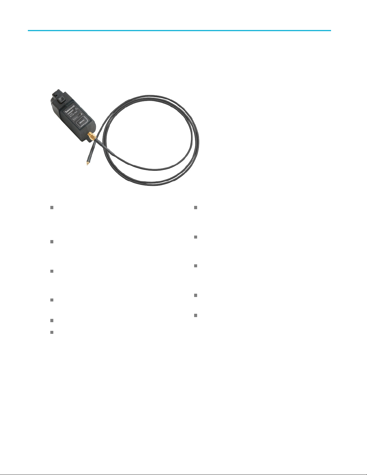
TPR1000 and TPR4000
Active Power Rail Probes
ZZZ
User Manual
*P077154200*
077-1542-00
Page 2

Page 3

xx
TPR1000 and TPR4000
Active Power Rail Probes
ZZZ
User Manual
www.tek.com
077-1542-00
Page 4

Copyright © Tektronix. All rights reserved. Licensed software products are owned by Tektronix or its subsidiaries or suppliers, and are
protected by na
tional copyright laws and international treaty provisions.
Tektronix pro
previously published material. Specifications and price change privileges reserved.
TEKTRONIX and TEK are registered trademarks of Tektronix, Inc.
TekVPI is a trademark of Tektronix, Inc.
ducts are covered by U.S. and foreign patents, issued and pending. Information in this publication supersedes that in all
Contacting Tektronix
Tektronix, Inc.
14150 SW Karl Braun Drive
P.O. Box 500
Beaverton, OR 97077
USA
For product information, sales, service, and technical support:
In North America, call 1-800-833-9200.
Worldwide, visit www.tek.com to find contacts in your area.
Page 5

Warranty
Tektronix warrants that this product will be free from defects in materials and workmanship for a period of one (1) year from the date of
shipment. If any such product proves defective during this warranty period, Tektronix, at its option, either will repair the defective
product without charge for parts and labor, or will provide a replacement in exchange for the defective product. Parts, modules and
replacement products used by Tektronix for warranty work may be new or reconditioned to like new performance. All replaced
parts, modules and products become the property of Tektronix.
In order to obtain service under this warranty, Customer must notify Tektronix of the defect before the expiration of the warranty period
and make suitable arrangements for the performance of service. Customer shall be responsible for packaging and shipping the
defective product to the service center designated by Tektronix, with shipping charges prepaid. Tektronix shall pay for the return of the
product to Customer if the shipment is to a location within the country in which the Tektronix service center is located. Customer shall
be responsible for paying all shipping charges, duties, taxes, and any other charges for products returned to any other locations.
This warranty shall not apply to any defect, failure or damage caused by improper use or improper or inadequate maintenance and
care. Tektronix shall not be obligated to furnish service under this warranty a) to repair damage resulting from attempts by personnel
other than Tektronix representatives to install, repair or service the product; b) to repair damage resulting from improper use or
connection to incompatible equipment; c) to repair any damage or malfunction caused by the use of non-Tektronix supplies; or
d) to service a product that has been modified or integrated with other products when the effect of such modification or integration
increases the time or difficulty of servicing the product.
THIS WARRANTY IS GIVEN BY TEK TR ON IX WITH RESPECT TO THE PRODUCT IN LIEU O F ANY OTHER WARRANTIES,
EXPRESS OR IMPLIED. TEKTRONIX AND ITS VENDORS DISCLAIM ANY IMPLIED WARRANTIES OF MERCHANTABILITY OR
FITNESS FOR A PARTICULAR PURPOSE. TEKTRONIX' RESPONSIBILITY TO REPAIR OR REPLACE DEFECTIVE PRODUCTS
IS THE SOLE AND EXCLUSIVE REMEDY PROVIDED TO THE CUSTOMER FOR BREACH OF THIS WARRANTY. TEKTRONIX
AND ITS VENDORS WILL NOT BE LIABLE FOR ANY INDIRECT, SPECIAL, INCIDENTAL, OR CONSEQUENTIAL DAMAGES
IRRESPECTIVE OF WHE THER TEKTRONIX OR THE VENDOR HAS ADVANCE NOTICE OF THE POSSIBILITY OF SUCH
DAMAGES.
[W2 – 15AUG04]
Page 6

Page 7

Table of Contents
Important Safety information .......................................................................................................... iii
General safety summary... . .. . . .. . . .. . ... . .. . . .. . . .. . ... . ... . ... . .. . . .. . . .. . ... . .. . . .. . . .. . . .. . ... . .. . . .. . . .. . ... . ... . ... . .. . . .. iii
Service safety summary ......................................................................................................... iii
Terms in this manual .. . . .. . ... . .. . . ... . .. . . .. . . .. . ... . ... . .. . . .. . . .. . . .. . . .. . ... . .. . . .. . . .. . . .. . ... . ... . ... . .. . . .. . . .. . ... . ... . .. iv
Symbols and terms on the product . ... . .. . . .. . . .. . ... . ... . ... . .. . . .. . . .. . ... . ... . .. . . .. . . .. . ... . ... . ... . .. . . .. . . .. . ... . ... . .. . . . iv
Compliance information ............................................................................................................... v
Environmental considerations ................................................................................................... v
Preface................................................................................................................................. vi
Documentation ...................................................................................................................vi
Conventions used in this manual. . . .. . ... . .. . . .. . . .. . ... . ... . ... . .. . . .. . . .. . ... . .. . . .. . . .. . ... . ... . .. . . .. . . .. . ... . .. . . .. . . .. . . .. vi
Returning the probe for servicing................................................................................................ vi
Why use a power-rail probe? ... . ... . .. . . ... . .. . . .. . . .. . . .. . . .. . . .. . . .. . . .. . . .. . . .. . ... . . .. . . .. . ... . . .. . ... . ... . ... . ... . ... . .. . . v
Theory of operation . . ... . ... . ... . .. . . .. . . .. . ... . .. . . .. . . .. . . .. . ... . .. . . .. . . .. . ... . ... . ... . .. . . .. . . .. . ... . .. . . .. . . .. . ... . ... . .. . . vii
Key features.................................................................................................................... viii
Installation.............................................................................................................................. 1
Operating considerations........................................................................................................ 1
Connecting to the host instrument. . ... . .. . . .. . . .. . ... . .. . . .. . . .. . ... . .. . . .. . ... . .. . . .. . . .. . ... . .. . . .. . . .. . ... . .. . . .. . ... . .. . . .. . 2
Probe controls and indicators.................................................................................................... 2
Functional check. .. . ... . ... . .. . . .. . . .. . ... . . .. . ... . ... . .. . . .. . . .. . ... . . .. . ... . ... . .. . . .. . . .. . ... . . .. . ... . .. . . .. . . .. . . .. . ... . . .. . ....... 4
Required equipment ... . .. . . .. . . .. . . .. . ... . . .. . ... . ... . .. . . ... . .. . . .. . . .. . . .. . ... . . .. . ... . ... . .. . . ... . .. . . .. . . .. . . .. . ... . . .. . ... . 4
Basic operation . . ... . .. . . .. . . .. . .. . . .. . ... . .. . . .. . ... . .. . . .. . . .. . .. . . .. . ... . .. . . .. . ... . .. . . .. . . .. . .. . . .. . ... . .. . . .. . ... . .. . . .. . . ....... 6
Required oscilloscope software versions . . .. . ... . .. . . .. . . .. . ... . .. . . .. . . .. . ... . .. . . .. . . .. . ... . .. . . .. . . .. . ... . ... . .. . . .. . ... . ... 6
Probe input . .. . ... . ... . .. . . ... . .. . . .. . . .. . . .. . ... . ... . ... . .. . . .. . . .. . . .. . ... . . .. . ... . ... . .. . . .. . . .. . . .. . . .. . ... . ... . .. . . ... . .. . . .. 6
Probe offset....................................................................................................................... 7
Connect MMCX accessories ... . ... . ... . ... . ... . .. . . ... . .. . . .. . . .. . . .. . . .. . . .. . . .. . ... . . .. . ... . ... . ... . ... . ... . .. . . ... . .. . . .. . . . 7
Connect solder-in accessories .. . . .. . . .. . ... . .. . . .. . . .. . . .. . . .. . ... . ... . .. . . .. . . .. . ... . . .. . ... . .. . . .. . . .. . . .. . ... . ... . ... . .. . . .. 7
Using the solder-pin installation tool............................................................................................. 8
Using the tripod ..................................................................................................................9
Using the optional browser . . .. . . .. . ... . ... . ... . .. . . .. . . .. . . .. . ... . ... . ... . .. . . .. . . .. . . .. . ... . ... . ... . .. . . .. . . .. . . .. . ... . ... . ... . 9
Accessories and options ............................................................................................................. 11
Standard accessories . .. . . .. . . .. . . .. . . .. . ... . ... . .. . . .. . . .. . ... . ... . ... . .. . . .. . . .. . . .. . ... . .. . . .. . . .. . . .. . . .. . ... . ... . .. . . .. . . .. 11
Optional accessories.. . . .. . ... . .. . . .. . . .. . ... . .. . . .. . . .. . ... . ... . .. . . .. . . .. . ... . ... . .. . . .. . . .. . ... . .. . . .. . . .. . ... . .. . . .. . . .. . ... 12
Options .......................................................................................................................... 14
Probing principles..................................................................................................................... 15
Ground lead length. .. . . .. . ... . ... . .. . . .. . . .. . ... . ... . ... . .. . . .. . . .. . . .. . ... . .. . . ... . .. . . .. . . .. . ... . ... . .. . . .. . . .. . ... . . .. . ... . .. 15
Ground lead inductance . .. . . .. . ... . ... . .. . . .. . . .. . ... . ... . ... . .. . . .. . . .. . . .. . ... . .. . . ... . .. . . .. . . .. . ... . ... . .. . . .. . . .. . ... . . .. . ... ... 16
Specifications .........................................................................................................................17
Warranted characteristics....................................................................................................... 17
Typical characteristics........................................................................................................... 18
Nominal characteristics ......................................................................................................... 21
Accessory characteristics....................................................................................................... 21
Table of Content
s
ii
TPR1000 and TPR4000 User Manual i
Page 8

Table of Content
Performance verification.............................................................................................................. 26
Maintenance ... . .. . . .. . . .. . ... . .. . . .. . ... . .. . . .. . . .. . ... . .. . . .. . . .. . ... . .. . . .. . . .. . ... . .. . ... . .. . . .. . . .. . ... . .. . . .. . . .. . ... . .. . . ...... 35
Index
s
Equipment requ
Equipment setup ................................................................................................................ 27
Check the DCgain accuracy ................................................................................................... 29
Check the DC in
Check the input offset range and scale accuracy.. . . .. . . .. . . .. . . .. . ... . ... . ... . ... . .. . . .. . . .. . . .. . . .. . . .. . ... . ... . ... . ... . .. . . 32
Check the analog bandwidth ... . ... . . .. . ... . .. . . .. . . .. . . .. . ... . . .. . ... . .. . . .. . . .. . . .. . ... . ... . ... . .. . . .. . . .. . . .. . ... . ... . ... . .. 33
Test record....................................................................................................................... 3
Error c ondition . ... . .. . . .. . . .. . . .. . ... . .. . . .. . . .. . ... . ... . ... . .. . . .. . . .. . ... . .. . . .. . . .. . ... . ... . .. . . .. . . .. . ... . .. . . .. . . .. . . .. . . . .. 35
Replacemen
Cleaning . . .. . ... . ... . ... . .. . . .. . . .. . ... . ... . .. . . .. . . .. . ... . ... . ... . .. . . .. . . .. . ... . ... . .. . . .. . . .. . ... . ... . ... . .. . . .. . . .. . ... . ... .. 35
ired ............................................................................................................. 26
put dynamic range ... . .. . . .. . . .. . . .. . . .. . ... . ... . ... . ... . .. . . .. . . .. . . .. . ... . ... . ... . .. . . .. . . .. . . .. . . .. . . .. . ... 31
t parts.............................................................................................................. 35
4
ii TPR1000 and TPR4000 User Manual
Page 9
Important Safet
y information
Important Saf
This manual contains information and warnings that must be followed by the user for safe operation and to keep the
product in a safe condition.
To safely perform service on this product, additional information is provided at the end of this section in the Service safety
summary.
ety information
General safety summary
Use the prod
or any products connected to it. Carefully read all instructions. Retain these instructions for future reference.
Probes and test leads
Before connecting probes or test leads, connect the power cord from the power connector to a properly grounded power
outlet.
Inspect the probe and accessories.
defects in the probe body, accessories, or cable jacket). Do not use if damaged.
High tem
uct only as specified. Review the following safety precautions to avoid injury and prevent damage to this product
perature probe tips
Before each use, inspect probe and accessories for damage (cuts, tears, or
WARNING. To prevent a burn injury, when using a solder micro-coax or flex tip in a high temperature application, be
sure to allow the tip to cool down before handling the tip.
Servicesafetysummary
The Service safety summary section contains additional information required to safely perform service on the product. Only
qualified personnel should perform service procedures. Read this Service safety summary and the General safety summary
before performing any service procedures.
Do not service alone.
rendering fi
rst aid and resuscitation is present.
Do not perform internal service or adjustments of this product unless another person capable of
TPR1000 and TPR4000 User Manual iii
Page 10
Important Safet
y information
Terms in this manual
These terms may appear in this manual:
WARNING. Warning statements identify conditions or practices that could result in injury or loss of life.
CAUTION. Caution statements identify conditions or practices that could result in damage to this product or other property.
Symbols and terms on the product
When this symbol is marked on the product, be sure to consult the manual to find out the nature of the
potential hazards and any actions which have to be taken to avoid them. (This symbol may also be used to
refer the user to ratings in the manual.)
The following symbol(s) may appear on the product:
iv TPR1000 and TPR4000 User Manual
Page 11

Compliance info
rmation
Compliance in
This product is intended for use by professionals and trained personnel only; it is not designed for use in households or
by children.
Questions about the following compliance information may be directed to the following address:
Te ktronix, Inc.
PO Box 500, MS 19-045
Beaverton, OR 97077, USA
www.tek.com
formation
Environmental considerations
This section provides information about the environmental impact of the product.
Restrict
Complies with RoHS2 Directive 2011/65/EU.
Product end-of-life handling
Observe
ion of hazardous substances
the following guidelines when recycling an instrument or component:
Equipment recycling.
may contain substances that could b e harmful to the environment or human health if improperly handled at the product’s
end of life. To avoid release of such substances into the environment and to reduce the use of natural resources, we
encourage you to recycle this product in an appropriate system that will ensure that most of the materials are reused
or recycled appropriately.
This symbol indicates that this product complies with the applicable European Union requirements according
to Directives 2012/19/EU and 2006/66/EC on waste electrical and electronic equipment (WEEE) and batteries.
For information about recycling options, check the Tektronix Web site (www.tek.com/productrecycling).
Production of this equipment required the extraction and use of natural resources. The equipment
TPR1000 and TPR4000 User Manual v
Page 12
Preface
Preface
This manual describes the installation and operation of the TPR1000 and TPR4000 active power rail probes. Basic probe
operations and concepts are presented in this manual. The 6 Series MSO oscilloscope and the TPR4000 probe is used
in all illustrations in this manual, unless noted otherwise. You can access this document and other related information
from the Tektronix website (www.tek.com).
Documentation
To read about Use these documents
TPR1000 and TPR4000 Probes: First Time Operation, Functional Check,
Operating Basics, Specifications, Performance Verification
Conventions used in this manual
The following icon is used throughout this manual to indicate a step sequence.
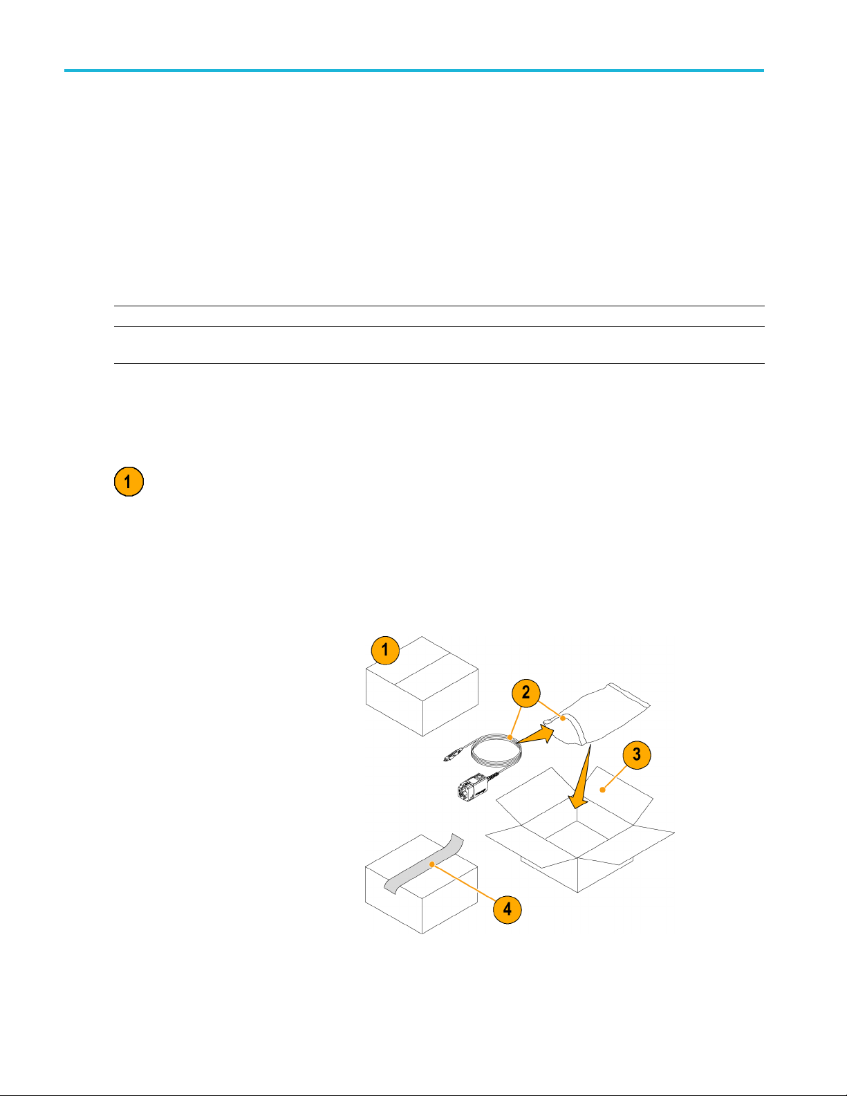
Returning the probe for servicing
If your probe requires servicing, you must return the probe to Tektronix. If the original packaging is un fit for use or not
available, use the following packaging guidelines:
Preparation for shipment
1. Use a corrugated cardboard shipping
carton having inside dimensions at
least one inch greater than the probe
dimensions. The box should have a
carton test strength of at least 200
pounds.
Read this Instruction Manual.
2. Put the probe into an antistatic bag or
wrap it to protect it from dampness.
3. Place the probe into the box and stabilize
it with light packing material.
4. Seal the carton with shipping tape.
5. Refer to Contacting Tektronix at the
beginning of this manual for the shipping
address.
vi TPR1000 and TPR4000 User Manual
Page 13
Whyuseapower-railprobe?
The added functionality, higher density, and faster switching speeds of modern electronic products drive the need for lower
supply voltages. Designers need to zoom-in on power rails to look for high-frequency intruder signals, measure ripple and
analyze coupling effects with tighter tolerances. Oscilloscopes often do not have enough offset to shift the noise and ripple
on DC rails to the center of the screen to make the needed measurements.
The TPR1000 and TPR4000 probes provide a low-noise measurement solution (oscilloscope and probe), which is critical to
not confuse the noise of the oscilloscope and probe with the noise and ripple of the DC supply being measured. The higher
input impedance in the probes minimize the oscilloscope loading effect on DC rails (50 kΩ at DC). The probes provide higher
bandwidth to see more signal content (harmonics, faster ripples, e tc.) on DC rails that could affect data signals, clocks, etc.
The TPR1000 and TPR4000 provide a best-in-class solution for power integrity and validation engineers in the high speed
(μP), low power (mobile) and switched-mode power supply markets. The probes are designed to offer the lowest noise
with high bandwidth at 60 V offset, flexible connectivity options to cover customers challenges, and software packages to
cover the digital power management market.
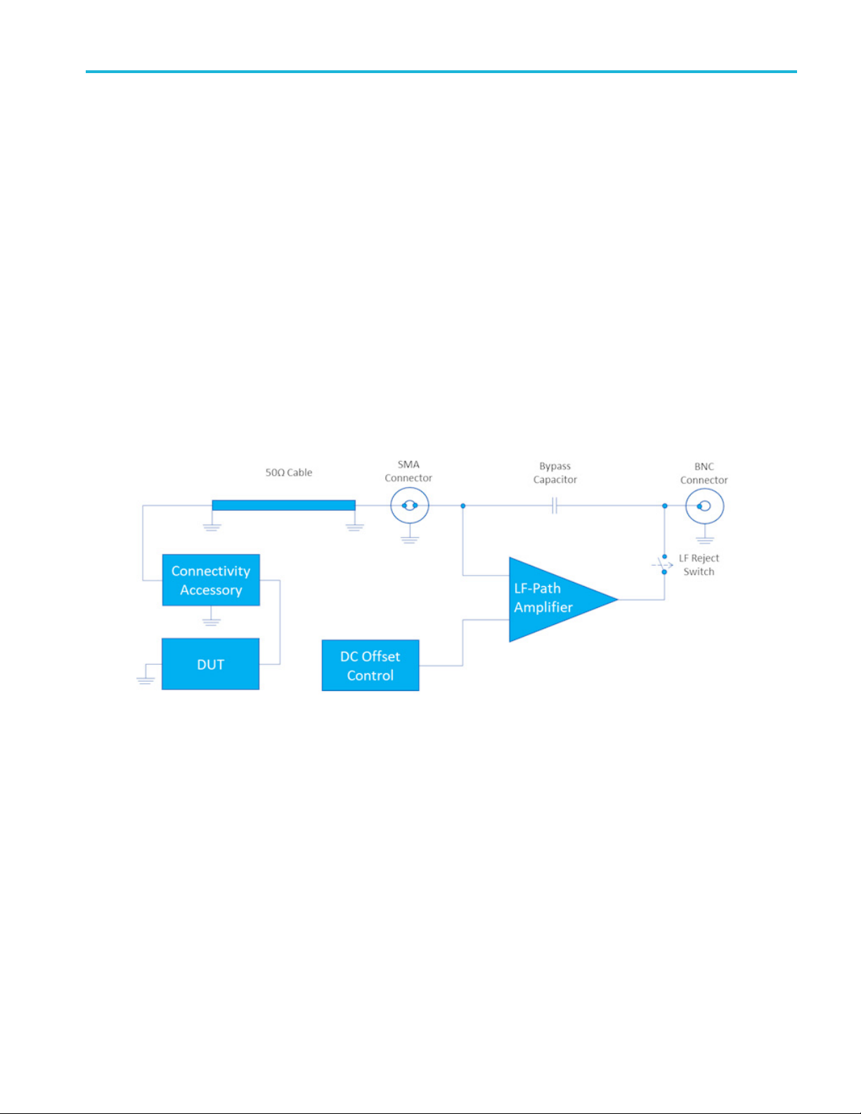
Theory of operation
The block diagram shows the major circuit blocks or modules in the TPR1000 and TPR4000 probes.
Preface
Figure i: TPR1000 and TPR4000 clock diagram
The TPR1000 and TPR4000 function by extending the oscilloscopes offset capability while maintaining a low noise signal
path into the instrument. The linear dynamic range can be moved around the offset voltage operating window using the
DC offset control into the LF amplifier. The LF amplifier can be disconnected when DC offset is not needed by setting the
coupling mode to DC reject in the instrument vertical menu. The bypass capacitor acts as a low impedance path for high
frequency components while blocking low frequency components. Because the TPR1000 and TPR4000 are designed for
measuring the low source impedances of power distribution planes it is not recommended to measure devices with source
impedances >1 Ω as it may cause distortion of the waveform.
TPR1000 and TPR4000 User Manual vii
Page 14
Preface
Key features
The TPR1000 and TPR4000 probes provide a low noise, large offset range solution for measurement of ripple on DC power
rails ranging from –60 to +60 VDC. Tektronix’s power rail probes offer industry leading low noise and high offset range
required to measure AC ripple between 200 μVp-p and 1 Vp-p at up to 4 GHz. Key features include:
Oscilloscope compatibility
6 series MSO, 5 series MSO, 4 series MSO, 3 series
MDO, MDO3000
DPO7000C, and DPO70000C/DX/SX
Bandwidth (DC coupling mode)
1
, MDO4000C1, MSO/DPO5000B,
2
34
TPR1000: DC to 1 GHz
Noise
<200 μVp-p noise on 6 Series MSO (20 MHz BW Limit)
<1 mVp-p noise on 6 Series MSO (Full Bandwidth)
Input impedance
50 kΩ DC to 10 Hz
50 Ω AC > 100 kHz
TPR4000: DC to 4 GHz
6
Bandwidth (DC reject mode)
TPR1000: 10 kHz to 1 GHz
34
Temperature range at tip
–40 to +85 °C (standard accessories)
–40 to +155 °C (high temperature cable option)
TPR4000: 10 kHz to 4 GHz
Offset
Linear dynamic range
Up to 60 V DC, 1 Vp-p to bandwidth
Attenuation: 1.25x
3
Measurement accuracy
5
±60 V offset range
Offset setting error
Max: ±(2% of setting value + 2.5 mV)
Typical: ±(0.1% + 2.5 mV) after SPC and Probe Zero
DC linearity: <0.1%
Step response long-term aberrations: <±1%
1
Due to software incompatibilities between the TPR1000 and TPR4000 probes and the MDO3000 and MDO4000C oscilloscopes, the accuracy
of probe measurements is reduced when these oscilloscopes are used in vertical scale settings less than 2 mV/division. For all other vertical
scale settings, the specified accuracy of the probe is maintained.
2
DPO70000 oscilloscopes require the optional TCA-VPI50 adapter.
3
Frequency response optimized for <1 Ω source impedance.
4
Through SMA-to-SMA cable or Solder Micro-Coax tip.
5
Max AC RMS of 1 V.
6
The comp box and oscilloscope temperature range is limited to the oscilloscope operating conditions. Please refer to the oscilloscope specifications.
viii TPR1000 and TPR4000 User Manual
Page 15

Installation
Operating considerations
TPR1000 and TPR4000 power rail probe operating considerations.
Table 1 : Environmental characteristics
Characteristic Description
Temperature (comp box) Operating: 0 to +50 °C (+32 to +122 °F)
Temperature (standard accessories)
Temperature (optional high temperature
accessories)
Humidity (operating and nonoperating) 5-95% RH, tested up to +40 °C (+104 °F)
Altitude
Dynamics (random vibration) Operating: 5 to 500 Hz, 2.66 gRMS
1
Operation temperature when using the standard accessory kit (TPR4KIT).
2
Operation temperature when using the optional high temperature accessory kit (TPR4KITHT).
2
Nonoperating: -20 to +85 °C (-4 to +185 °F)
1
Operating: -40 to +125 °C (-40 to +257 °F)
Operating: -55 to +155 °C (-67 to +311 °F)
5-85% RH, tested above +40 °C (+104 °F)
Operating: Up to 3000 meters (9,843 feet),
Nonoperating: Up to 12,000 meters (39,370 feet)
Nonoperating: 5 to 500 Hz, 3.48 gRMS
Installation
TPR1000 and TPR4000 User Manual 1
Page 16

Installation
Connecting to the host instrument
1. Slide the probe body into the FlexChannel
or VPI receptacle. The probe clicks into
place when fully engaged.
When the probe is connected, the host
instrument reads information from the
probe and identifies the device.
NOTE. Allow the probe to warm up for at
least 20 minutes to achieve guaranteed
specifications.
2. Attach one of the following probe cables
to the SMA connector on the probe body.
Limit SMA nut torque to 8 in-lbs for either
attachment or removal:
SMA-to-SMA standard cable (standard
accessory)
SMA-to-MMCX standard cable (standard
accessory)
SMA-to-MMCX high-temperature cable
(optional accessory)
1 GHz browser probe cable (optional
accessory)
3. To disconnect, press the latch release
button and pull away from the instrument.
Probe controls and indicators
Status LED
When the probe is powered on, the multicolor
Status LED:
A solid green LED indicates t
probe has initialized and is in the normal
operating mode.
A flashing green LED indicates that
the probe is connected, but
initialized.
hat the
has not
A red LED in any state indicates an error
condition exists. (See page 35, Error
condition.)
2 TPR1000 and TPR4000 User Manual
Page 17

Menu button
1. Press the probe Menu button to display
the Probe Control screen on the
oscilloscope.
2. Use the touch-screen buttons on the
instrument to set the probe parameters.
3. Press the probe Menu button again to
close the Probe Control screen.
AutoZero
We recommend that you run the probe
AutoZero r
outine:
Installation
After the
When the o
probe changes by ±5 °C
1. Press the probe Menu button to display
the Probe Control screen on the
oscillo
2. Short th
3. Press th
instrument to execute the AutoZero
routine.
20 minute warm-up period
perating temperature of the
scope.
e probe tip to ground.
e AutoZero buttononthe
TPR1000 and TPR4000 User Manual 3
Page 18

Functional chec
k
Functional check
Use the following procedure to check that your probe is functioning properly. To verify that your probe meets the warranted
specifications, refer to the Performance Verification procedures. (See page 26.)
Required equipment
Description and quantity Performance requirement Recommended example
Oscilloscope TekVP I Interface Tektronix DPO7000 Series
SMA cable 1.3 m cable, SMA male-to-SMA male,
Sine wave generator
50 Ω
Frequency: 10 Mhz
Amplitude: 1 Vpp, Offset 1 Vpp
Tektronix 3 Series MDO
Tektronix 4 Series MSO
Tektronix 5 Series MSO
Tektronix 6 Series MSO
Cable included in standard accessory
kit (TPR4KIT)
Figure 1: Functional check connection diagram
1. Connect the probe to the oscilloscope and a function generator as detailed in the connection diagram. (See Figure 1.)
2. If the function generator allows load impedance scaling, set the load impedance to high-Z. Otherwise, place a 50 Ω feed
through terminator between the SMA cable and the probe.
4 TPR1000 and TPR4000 User Manual
Page 19

3. Set the probes offset to 1 V and the vertical scale to 200 mV/div.
4. Set the function generator to 1 Vpp amplitude 1 V offset and the function to a 10 MHz sine wave.
5. The instrument should show a 1 Vpp sine wave on the screen centered around 1 V.
6. Open the vertical channel menu and change the coupling mode to DC reject.
7. Set the vertical offset to 0 V.
8. Confirm that the signal is centered around 0 V.
Functional chec
k
TPR1000 and TPR4000 User Manual 5
Page 20

Basic operation
Basic operation
Follow these operating guidelines to get the best performance from your probe.
Required oscilloscope software versions
Oscilloscope Required software version
3 series MDO, 4 Series MSO, 5 Series MSO and 6 Series
MSO
MDO3000
MDO4000C
MSO/DPO5000B
DPO7000C
DPO70000C/DX/SX
1
The probe may operate with older versions of oscilloscope software. However, older software versions than those listed are not guaranteed to
provide full probe functionality.
Probe input
The probe is electrically protected against static voltage. However, applying voltages above its design limits may damage the
probe tip amplifier. (See Figure 2 on page 6.)
Input Linear Dynamic Range
The probe head amplifier used by the probe has a limited linear operating range. To keep the input linearity error within
specification, you m ust limit the signal input voltage to ±1 V.
1
1.12.5
1.27462
1.09354
10.8.3.3
10.8.3.3
10.9.1
Figure 2: Dynamic and Offset Limitations
6 TPR1000 and TPR4000 User Manual
Page 21

Probe offset
The probe offset is adjustable for operation within the linear range of the probe, and to increase the sensitivity of the probe at
higher DC measurement voltages. Using the offset to cancel DC signal components enables optimal probe performance.
(See Figure 2 on page 6.)
NOTE. See your oscilloscope manual for specific instructions on using the offset control.
To set the probe offset, follow these steps:
1. Set the probe offset equal to the expected nominal DC value of the source you are connecting to.
2. Set the vertical scale to 500 mV/div.
3. Connect the probe to the circuit.
4. Change the volts/div setting to the desired range, adjusting the offset as needed to keep the signal in the center of
the screen.
The probe has a ±60 V offset range. The linear operating r ange is ±1 V. (See Figure 2 on page 6.) When you adjust the
probe offset with no signal applied to the probe input, the output range is ±1 V, (the linear operating range of the probe),
not the ±60 V offset range of the probe. However, when you apply up to ±60 V to the probe input, the probe offset control
canzerothisoffset.
Basic operation
NOTE. If the signal on the screen displays an offset that is either 1 Volt higher or lower than expected, check to make sure
the DUT is connected and operating. This is a result of the input to the LF amplifier being clamped at one extreme of
the dynamic range when no input is present.
Connect MMCX accessories
Gently insert the MMCX end of the cable into one of the following accessories: micro-coax tip, solder flex tip, u.fl adapter or
MMCX to square pin Y-lead adapter, until you feel the connector engage. To remove an accessory, gently pull from the
MMCX connection point, being careful to only grip the knurled metal area of the connector.
Connect solder-in accessories
Micro-coax tip.
soldered to the test point. You can reuse a tip by removing the tip from the solder joint and then trimming the wire insulation
back to expose the center pin and ground shield on the tip cable.
For convenient first-time use, the solder micro-coax tips are shipped pre-trimmed and ready to be
TPR1000 and TPR4000 User Manual 7
Page 22

Basic operation
Flex tip.
point. Feed the
attach the wire to the tip.
To attach the solder flex tip, first solder the enameled self-fluxing copper wire (standard accessory) to the test
wire through the vias on the end of the flex tip, and then apply a small amount of solder to the vias to
Using the solder-pin installation tool
The supplied set of solder pins are intended to be installed on DUT circuit boards and used with the supplied
MMCX-to-square-pin adapter. To install the solder pins, use the supplied soldering-aide tool as described below
NOTE. The solder pins are extremely small and can be challenging to handle. It is recommended to use tweezers and
a magnifying tool when installing pins on a circuit board.
1. Carefully insert the solder pins into the soldering aide tool as shown below.
2. Use the soldering aide tool to hold the solder pins in place while soldering the pins to the circuit board.
3. If necessary, apply a small amount of adhesive to further strengthen the connection to the circuit board. However, keep
the height of the adhesive to a minimum to provide good electrical contact for the adapter.
8 TPR1000 and TPR4000 User Manual
Page 23

Using the tripod
The tripod probe support adds stability to square-pin mounted test points. For m ore stability, use glue to attach the tripod legs
to the DUT circuit board.
Using the optional browser
Basic operation
The optional browser kit contains the following parts: up to 1 GHz browser probe, square pin Y-lead adapter, micro-SMD clip,
three ground leads (alligator, blade, spring), and four replacement probe-tip pins (two rigid, two spring loaded).
WARNING. To prevent injury to the operator or damage to the probe, oscilloscope and device under test, do not touch the
probe ground to any point that is not at the same potential as the chassis ground of the oscilloscope. The probe ground must
be connected to the same potential as the chassis ground of the oscilloscope.
Installing ground leads.
measurements. It is recommended that you use the shortest ground lead that will function in your electrical application. The
following illustration shows the browser probe tip, the tip cover and the three types of grounds leads supplied with the browser.
To install the ground leads:
To obtain accurate m easurements, always attach a ground lead to the probe tip before making
Spring: Slide the ground lead over the probe tip until it seats around the metal part of the probe-tip housing.
Alligator: Slide the ground lead prongs over the exposed metal between the plastic probe-tip sections.
Blade: Locate the slot in the probe-tip housing as shown below. Slide the ground lead over the probe tip until the
blade slides into the slot.
TPR1000 and TPR4000 User Manual 9
Page 24

Basic operation
Connecting the Y-lead adapter and micro-SMD clip.
clip that co
Replacing browser-tip pins.
housi
use pliers to gently insert the pin into the browser-tip housing until you feel the pin press against the bottom of the housing.
nnect as shown below. The Y-lead adapter can also connect to square pins.
To remove the browser-tip pin, use pliers to grasp the pin and gently pull it out of the tip
ng. To install a new browser-tip pin, select between a solid (silver colored) or spring-loaded (gold colored) pin, and then
The browser kit includes a Y-lead adapter and a micro-SMD
10 TPR1000 and TPR4000 User Manual
Page 25

Accessories and options
This section lists the standard accessories and provides information on how to use the accessories. Specifications are
provided where appropriate so that you can choose the accessory that best fits your needs. In some cases, reorder kit
quantities differ from the actual number of accessories included with the probe.
Standard accessories
Each probe is shipped with one TPR4KIT accessory kit containing the following items:
Item
1.3 m cable, SMA male-to-MMCX male, 50 Ω
1.3 m cable, SMA male-to-SMA male, 50 Ω
Accessories and
options
Y-lead adapter, MMCX female-to-0.8 mm sockets
Adapter cable, MMCX female-to-U.FL female, 50 Ω
Adapter, MMCX female-to-square pin (0.062 centers)
DUT interface solder pins, set of 20
Soldering aide tool, 0.062 solder pins over SMT
TPR1000 and TPR4000 User Manual 11
Page 26

Accessories and
Item
Solder-in c able adapter, MMCX female-to-solder micro-coax tip, 50 Ω, set of 3
Solder-in c able adapter, MMCX female-to-solder flex-paddle tip, 50 Ω, set of 3
Wire card, solderable enameled self-fluxing copper wire (for use with the solder-in tips)
Probe tip tripod support (with living hinge)
options
Marker ban
ds, set of 5 (for probe identification)
Optional accessories
This section lists the optional accessories that you can purchase to help you with your probing tasks.
onal TPR4KITHT high-temperature accessory kit i ncludes the following items:
The opti
Item
2 m high
Solder-in c able adapter, MMCX female-to-solder micro-coax tip, 50 Ω, set of 3
Solder-in c able adapter, MMCX female-to-solder flex-paddle tip, 50 Ω, set of 3
-temperature cable, SMA male-to-MMCX male, 50 Ω
12 TPR1000 and TPR4000 User Manual
Page 27

The optional TPRBRWSR1G browser accessory kit includes the following items:
Item
Browser
Ground leads (blade, 0.5 mm spring, 15 cm alligator)
Y-lead adapter, browser tip-to-0.8 mm sockets
Micro-SMD clip
Accessories and
options
Replacem
ent 0.5 mm browser tips (2 solid tips, 2 spring tips)
The optional TPR4SIACOAX accessory kit includes the following items:
Item
Solder-in cable adapter, MMCX female-to-solder micro-coax tip, 50 Ω, set of 3
The optional TPR4SIAFLEX accessory kit includes the following items:
Item
Solder-in cable adapter, MMCX female-to-solder flex-paddle tip, 50 Ω, set of 3
TPR1000 and TPR4000 User Manual 13
Page 28

Accessories and
Options
Service Options
Option CA1. Provides coverage for a single Calibration Event
Option C3. Calibration Service 3 years
Option C5. Calibration Service 5 years
Option D1. Calibration Data Report
Option D3. Calibration Data Report, 3 years (with Option C3)
Option D5. Calibration Data Report, 5 years (with Option C5)
Option R3. Repair Service 3 years
Option R5. Repair Service 5 years
options
Manual Op
Option L0. English language Instruction Manual
Option L5. Japanese language Instruction Manual
Option L7. Simplified Chinese language Instruction Manual
tions
14 TPR1000 and TPR4000 User Manual
Page 29

Probing principles
Follow these helpful hints to make probing easier and noise free.
Ground lead length
When you are probing a circuit, you should
always use as short a ground lead as
possible between the probe head and circuit
ground. (See the illustration for the effects of
lead length on waveform distortion.)
The series inductance added by the probe
tip and ground lead can result in a resonant
circuit; this circuit may cause parasitic ringing
within the bandwidth of your oscilloscope.
Probing princip
les
TPR1000 and TPR4000 User Manual 15
Page 30

Ground lead indu
ctance
Ground lead in
When you touch your probe tip to a circuit element, you are introducing a new resistance, capacitance, and inductance
into the circuit.
You can determine if ground lead effects may
be a problem in your application if you know
the self-inductance (L) and capacitance (C)
of your probe and ground lead. Calculate the
approximate resonant frequency (f
this parasitic circuit will resonate with the
following formula:
The equation shows that reducing the ground
lead inductance will raise the resonant
frequency. If your measurements are
affected by ringing, your goal is to lower
the inductance of your ground path until the
resulting resonant frequency is well above
the frequency of your measurements.
The low-inductance ground contacts
described in Accessories can help you
reduce the effects of ground lead inductance
on your measurements.
ductance
)atwhich
0
16 TPR1000 and TPR4000 User Manual
Page 31

Specifications
Specification
The specifications are valid under the following conditions:
The probe has been calibrated at an ambient temperature of 23 °C ±5 °C.
The probe is connected to a host instrument with an input impedance of 50 Ω.
The probe and oscilloscope must have a warm-up period of at least 20 minutes and be in an environment that does not
exceed the limits described. (See Table 1.)
The Signal Path Compensation (SPC) has been run on the oscilloscope before testing the probe specifications.
Specifications for the TPR1000 and TPR4000 power rail probes fall into three categories: warranted, typical, and nominal
characteristics. The warranted, typical, and mechanical characteristics apply to the TPR1000 and TPR4000 probes unless
noted otherwise. Environmental characteristics are in the Operating considerations section. (See Table 1.)
s
Warranted characteristics
Warranted characteristics describe guaranteed performance within tolerance limits or certain type-tested requirements.
Warranted characteristics that have checks in the Performance Verification section are marked with the
Table 2: Warranted electrical characteristics
Characteristic Description
DC attenuation
DC attenuation accuracy
Analog b
configuration)
DC input dynamic range
Offset scale accuracy
andwidth (SMA
symbol.
1.25x
<±1% within 80% of DC dynamic range
1 GHz (TPR1000)
4 GHz (TPR4000)
>±1 V
±(2% of setting value + 2.5 mV max)
Typical value is ±(0.1% + 2.5 mV) after SPC and Probe Zero
TPR1000 and TPR4000 User Manual 17
Page 32

Specifications
Typical characteristics
Typical characteristics describe typical but not guaranteed performance.
Table 3: Typical electrical characteristics
Characteristic Description
DC input resistance 50 kΩ
Return loss
DC to AC impedance crossover
frequency
DC to AC gain matching ±1%
Risetime (small signal, 20% to 80%) 282 pS (TPR1000)
Risetime (small signal, 10% to 90%) 408 pS (TPR1000)
Step Response Long Term Aberrations <1% of final value after 50 μS
Delay time (comp box only) 565 ps ±20% (TPR1000)
Delay time for each accessory 6.19 ns ±10% (1.3 m MMCX cable)
Delay time (default configuration)
Maximum: -12 dB between 10 MHz and 1 GHz (TPR1000)
Maximum: -12 dB between 10 MHz and 4 GHz (TPR4000)
300 Hz
88 pS (TPR4000)
128 pS (TPR4000)
475 ps ±20% (TPR4000)
9.47 ns ±10% (2 m MMCX cable)
494 pS ±20% (10 cm blue coax solder-in)
500 pS ±20% (10 cm Flex Paddle Adapter)
484 pS ±20% (U.FL to MMCX Adapter)
5.2 nS ±10% (Browser)
7.12 nS
1
1
NOTE. Base configuration consists of
1.3 m SMA to MMCX cable + MMCX
micro coax tip (TRPSIACOAX)
Noise
Noise (probe only, DC to 20 MHz )
Typical: <25% RMS additive to oscilloscope at full bandwidth
Maximum: 220 μVp-p
Typical: 165 μV p-p into 6-series MS O
Input common mode rejection -20 dB 20 Hz up to probe bandwidth
1
50 Ω reference impedance
18 TPR1000 and TPR4000 User Manual
Page 33

Figure 3: TPR1000 frequency response
Specifications
e 4: TPR4000 frequency response
Figur
TPR1000 and TPR4000 User Manual 19
Page 34

Specifications
Figure 5: TPR1000 and TPR4000 input impedance and phase versus frequency
Table 4: Probe typical mechanical characteristics
Characteristic Description
Dimensions, compensation box
Packaged weight
85.1 mm × 40.6 mm × 30.5 mm (3.4 in × 1.6 i n × 1.2 in)
1.24 kg (2.7 lbs)
20 TPR1000 and TPR4000 User Manual
Page 35

Nominal characteristics
Nominal characteristics describe guaranteed traits, but the traits do not have tolerance limits.
Table 5: Nominal electrical characteristics
Characteristic Description
Compatibility Oscilloscopes equipped with the TekVPI interface
Instrument coupling
Input offset requestable range
Non-destructive input voltage range (AC
frequency above 10 kHz)
Specifications
DC, LF‐Reject
±60 V
2.5 VRMS, with peaks ≤±20 V (DF 6.25%)
Input connector on Comp box SMA-female jack
Output connector on cable SMA-male plug
DUT connector on standard cable
DUT connector on optional cable
Insulation voltage rating
Accessory characteristics
Specifications for the TPR1000 and TPR4000 accessories fall into two categories: warranted and typical characteristics.
Table 6: Accessory electrical characteristics
Characteristic Description
TPR4SIAFLEX and TPRSIACOAX
(typical)
SMA to SMA cable (warranted) 1 GHz (TPR1000)
MMCX to U.FL adapter (typical) 1 GHz (TPR1000)
MMCX to square pin adapter (typical) 1 GHz (TPR1000)
MMCX-male plug
SMA-male plug
SMP-female jack
±30 V RMS (AC)
±42 V Peak (pk-pk)
±60 V DC (DC)
1 GHz (TPR1000)
>3.5 GHz (TPR4000)
4 GHz (TPR4000)
>2 GHz(TPR4000)
1 GHz (TPR4000)
TPR1000 and TPR4000 User Manual 21
Page 36

Specifications
Table 6: Accessory electrical characteristics (cont.)
Characteristic Description
2 M high temperature SMA to MMCX
cable (typical)
TPR4BRWSR1G (typical)
TPR4BRWSR1G (typical) 1 GHz with barrel adapter
Table 7: Accessory typical mechanical characteristics
Item number Dimensions
Rigid Browser
Tip
Pogo Browser
Tip
1 GHz (TPR1000)
>2 GHz (TPR4000)
>350 MHz with short ground
Browser
Browser
Spring Ground
22 TPR1000 and TPR4000 User Manual
Page 37

Table 7: Accessory typical mechanical characteristics (cont.)
Item number Dimensions
Browser Blade
Ground
Browser
Alligator
Ground
TPRSIACOAX
Specifications
TPRSIAFLEX
MMCX to U.FL
adapter
TPR1000 and TPR4000 User Manual 23
Page 38

Specifications
Table 7: Accessory typical mechanical characteristics (cont.)
Item number Dimensions
1.3 m SMA to
MMCX Cable
1.3 m SMA to
SMA Cable
2mSMAto
Cable
MMCX
Browser to
Square-pin
adapter
24 TPR1000 and TPR4000 User Manual
Page 39

Table 7: Accessory typical mechanical characteristics (cont.)
Item number Dimensions
MMCX to
Square-pin
adapter
SMT
Component
Clip
Specifications
TPR1000 and TPR4000 User Manual 25
Page 40

Performance ver
ification
Performance v
The procedures that follow verify the warranted specifications of the probe. The recommended calibration interval is one
year. Perform the verification procedures in the order listed.
erification
Equipment required
The following equipment is required for the performance verification procedures.
Table 8: Test equipment
Description and quantity Performance requirement Recommended example
Oscilloscope TekVP I Interface Tektronix 6 Series MSO
DC calibr
Digital m
Network Analyzer Tektronix VNA TTR506A
TekVPI Calibration Verification adapter TekVP I Interface
SMA to BNC adapter SMA male to BNC female
SMA to BNC adapter SMA female to BNC male
SMA to SMA adapter SMA male to SMA male
BNC-to-dual banana adapter (2)
BNC cable (2) 50 Ω, 0.76 m (30 in) length
Fee
SMA cable for network analyzer N to SMA-M 5 foot cable
SMA adapter for network analyzer Type-N male to Type-SMA female
SMA torque wrench 5/16-in, 7 in-lb.
SMA adapter wrench 7/32-in
1
ation source
ultimeter (DMM)
d-thru termination
Nine-digit part numbers (xxx-xxxx-xx) are Tektronix part numbers.
Resistan
50 Ω,1GHz,±0.5Ω
ce, 0.1% accuracy
8 Hz bandwi
Keithley
Keithley 2700 DMM
067-170
BN533828
015-05
015-0
015-0
103-
012-
-0049-XX
011
-1774-XX
012
3-0406-XX
01
dth option
2400 SMU
1-XX with Calibration kit
54-XX
572-XX
551-XX
0090-XX
0117-XX
1
26 TPR1000 and TPR4000 User Manual
Page 41

Equipment setup
Use the following procedures to set up and warm up the equipment to test the probe.
DC setup connection diagram
Use the DC setup diagram for the following performance checks.
DC gain accuracy (See page 29.)
DC input dynamic range (See page 31.)
Input offset range and scale accuracy (See page 32.)
Performance ver
ification
Figure 6: DC setup connection diagram
TPR1000 and TPR4000 User Manual 27
Page 42

Performance ver
Analyzer setup connection diagram
Use the analyzer setup diagram for the analog bandwidth performance check. (See page 33.)
ification
Figure 7: Analyzer setup connection diagram
28 TPR1000 and TPR4000 User Manual
Page 43

Warm up the test equipment
1. Turn on the TekVPI oscilloscope.
2. Connect the TekVPI Calibration/Verification adapter to the oscilloscope.
3. Connect the probe to the TekVPI Calibration Verification adapter and verify that the Status LED on the probe turns green.
4. Turn on the remaining test equipment.
5. Allow 20 m inutes for the equipment to warm up.
6. Use the test record template to record the test results.(S ee page 34, Te st r e co r d .)
Check the DC gain accuracy
Use the following test to check the DC gain accuracy of the probe.
1. Connect the test equipment as shown in the DC setup diagram. (See Figure 6.)
2. Before attaching the probe to the TekVPI Calibration Verification adapter, measure the resistance of the feed-thru
termination with the DMM.
3. Record its value. If it is out of specification, replace the precision terminator before continuing the test.
Performance ver
ification
4. Attach the probe to the TekVPI Calibration Verification adapter.
5. Ensure the probe offset is set to 0 V.
6. Set the digital multimeter (DMM) to the following settings.
DC Volts auto ranging
Filter mode on
Measurement rate slow
7. Set the DC source current limit to 3 mA.
8. Set the DC source to the first voltage level listed below. ( See Table 9.)
NOTE. When using the DMM function in a Keithley S MU, turn on FILTER to reduce transient output values.
9. On the DMM measure the probe response and record the level in the Vout (measured) column in the following table.
Table 9: DC source voltage levels
Index DC source voltage Vout (measured) Vout (linear fit)
–2 –640 mV –512 mV
–1 –320 mV –256 mV
00mV 0mV
1 320 mV 256 mV
2 640 mV 512 mV
10. Repeat steps 8 and 9 for each voltage level listed in the table. (See page 30, DC gain measurement example.)
TPR1000 and TPR4000 User Manual 29
Page 44

Performance ver
11. Perform a linear fit of the measured data points in the preceding table and record the linear fit values in the table.
12. Divide the measured linear fit slope by the slope of the DC source voltage points. (See page 30, DC gain measurement
example.)
ification
13. Record the Mea
sured Gain value in the test record. (See page 34.)
DC gain measurement example
1. The following table lists example measured values.
Table 1 0: Example DC gain measurements
Index DC source voltage Vout (measured) Vout (linear fit)
–2 –640 mV –513 mV –514 mV
–1 –320 mV –256 mV –257 mV
0 0 mV 0.0009 mV 0 mV
1 320 mV 258 mV 257 mV
2 640 mV 515 mV 514 mV
2. The graph below show the plotted example values.
Figure 8: Example plot of measured values
The gain slope can either be obtained by using a spreadsheet to calculate the linear regression of the points, or graphically
by hand. To obtain the gain slope graphically, carefully plot each measurement point on a rectangular coordinate system,
the X axis is the DC source voltage and the Y axis is the measured DC output value. Using a straight edge, draw a line
through the points, minimizing the error between the line and each point. The gain slope is taken by the slope of the
drawn line (rise in Y divided by run in X), and the zero point error taken at the point at which the line crosses the Y axis.
The DC output value can be predicted by the following equation:
3. The following table shows the measured gain as calculated from the slopes of the plotted measured values.
30 TPR1000 and TPR4000 User Manual
Page 45

Table 11: Example calculation of measured gain
Performance ver
ification
Vout (linear fit
)slope
Vin slope Measured gain
0.257 0.320 0.803125
Check the D C input dynamic range
Use the following test to check the DC input dynamic range of the probe.
1. Connect the test equipment as shown in the DC setup diagram. (See Figure 6.)
2. Before attaching the probe to the TekVPI Calibration Verification adapter, measure the resistance of the feed-thru
termination with the DMM.
3. Record its value. If it is out of specification, replace it before continuing the test.
4. Attach the probe to the TekVPI Calibration Verification adapter.
5. Ensure the probe offset is set to 0 V.
6. Set the DMM to DC Volts autoranging.
NOTE. When using the DMM function in a Keithley SMU, turn on FILTER to reduce transient output values.
7. Set the DC source current limit to 3 mA.
8. Set the source measure unit (SMU) to +1 V and record the output voltage on the D MM.
9. Set the source measure unit (SMU) to –1 V and record the output voltage on the DMM.
10. Using the readings taken in steps 8 and 9, apply the following equation to calculate the gain of the probe:
Gain
probe=Vsource÷Vmeasured
11. Verify that the gain is at l east 90% of the nominal gain range for each input by dividing it by the nominal expected gain
and multiplying by 100:
100 x Gain
measured
÷Gain
nominal
12. If the value is >90%, then that limit of the dynamic range is verified.
13. Record results in test record.
14. Switch the probe to DC Reject mode.
15. While measuring the output, apply +1 V and –1 V to the input of the probe.
16. Ensure that output does not shift by more than 0.01 V during the test. Result is reported as Pass or Fail.
17. Return the probe to DC Coupling mode.
18. Record the result in the test record. (See page 34.)
TPR1000 and TPR4000 User Manual 31
Page 46

Performance ver
ification
Check the input offset range and scale accuracy
Use the following test to check the input offset range and scale accuracy of the probe.
1. Connect the test equipment as shown in the DC setup diagram. (See F igure 6.)
2. Before attaching the probe to the TekVPI Calibration Verification adapter, measure the resistance of the feed-thru
termination with the DMM.
3. Record its value. If it is out of specification, replace it before c ontinuing the test.
4. Attach the probe to the TekVPI Calibration Verification adapter.
5. Set the DMM to DC Volts autoranging.
6. Set the DC source current limit to 3 mA.
7. Sweep the DC source through the discrete points listed in the following table and set the probe offset range to the same
set point using the Probe Setup window on the oscilloscope. Measure the probe response at each point with the D MM.
DC source voltage Probe vertical offset setting
+12 V +12 V
+1 V +1 V
–1 V –1 V
–12 V –12 V
8. Record the result of each setting in the test record. (See page 34.)
32 TPR1000 and TPR4000 User Manual
Page 47

Check the analog bandwidth
Use the following test to check the analog bandwidth of the probe.
1. Connect the test equipment as shown in the Analyzer setup diagram. (See Figure 7.)
2. Set the network analyzer to measure insertion loss (S21) in dB. Set the network analyzer to the following settings:
Power Level: –10 dBm
IF Bandwidth: 1 kHz
Sweep Type: Linear
Start Frequency: 300 kHz
Stop Frequency: 6 GHz
Number of points: 201
Set scale factor: 1 dB
For more information on setting up a network analyzer, use the following links:
tek.com/how/making-basic-2-port-measurements-using-ttr500-vna
tek.com/how/how-calibrate-ttr500-vector-network-analyzer
Performance ver
ification
3. Set up the network analyzer with a fresh 2-port SOLT calibration to the reference planes of the SMA side of network
analyzer cable (port 2) and the SMA side of the SMA-to-N adapter (port 1).
4. Place a marker on the S21 trace at the start frequency (300 kHz).
5. Place a marker on the S21 trace at the probe bandwidth (1 GHz for TPR1000 or 4 GHz for TPR4000).
6. Verify that the amplitude is greater than -3.97 dB (subtracting the 0.97 dB of probe attenuation range from the 3.97 dB
target value yields the 3 dB limit).
7. Record the result in the test record. (See page 34.)
TPR1000 and TPR4000 User Manual 33
Page 48

Performance ver
ification
Test record
Probe Model/Serial Number: _____________________ Certificate Number: __________________________
Temperature: _________________________________ RH %: ____________________________________
Date of Calibration: ____________________________ Technician: ________________________________
Performanc
DC gain a ccu
DC input dy
DC reject function Pass/Fail
Input offset range and scale accuracy
+12 V offset
+1 V offs
–1 V offset
–12 V offset
Analog
TPR1000
TPR4000
e test
racy
namic range
et
bandwidth
Minimum Measured / c
0.792 0.808
–1 V NA
NA +1 V
-194 mV 194 mV
-18mV 18mV
-194 mV 194 mV
-18mV 18mV
-3 dB NA
-3 dB NA
alculated
Maximum
34 TPR1000 and TPR4000 User Manual
Page 49

Maintenance
This section contains maintenance information for your probe.
Error condition
The TPR1000 and TPR4000 power rail probes are designed to work with all TekVPI-interface oscilloscopes and adapters.
However, the
re may be some cases where all of the probe features may not work properly.
Maintenance
If the Statu
and reconnect the probe to restart the power-on diagnostic s equence. If the Status LED continues to be red or fl ashing
for more than 30 seconds when the oscilloscope application is running, the probe is defective and must be returned to
Tektronix f
s LED is red or flashing during or after probe power on, an internal probe diagnostic fault exists. Disconnect
or repair.
Replacement parts
There are no user replaceable parts within the probe. Refer to Accessories for a list of replaceable accessories for your probe.
Cleaning
Protect the probe from adverse weather conditions. T he probe is not waterproof.
CAUTION. To prevent damage to the probe, do not expose it to sprays, liquids, or solvents. Avoid getting moisture inside
the prob
Do not use chemical cleaning agents; they may damage the probe. Avoid using chemicals that contain benzine, benzene,
toluene, xylene, acetone, or similar solvents.
Clean the exterior surfaces of the probe with a dry, lint-free cloth or a soft-bristle brush. If dirt remains, use a soft cloth or
swab dampened
enough solution to dampen the swab or c loth. Do not use abrasive compounds on any part of the probe.
e during exterior cleaning.
with a 75% isopropyl alcohol solution. A swab is useful for cleaning narrow spaces on the probe, use only
TPR1000 and TPR4000 User Manual 35
Page 50

Maintenance
36 TPR1000 and TPR4000 User Manual
Page 51

Index
Index
A
Accessories
connect MMCX accessories, 7
connect solder-in
accessories
optional, 12
standard, 11
using the op
browse, 9
using the solder-pin installation
tool, 8
using the tripod, 9
Analog bandwidth
performan
AutoZero, 3
,7
tional 1 GHz
ce check, 33
C
Cleaning the probe, 35
Connecti
ng the probe, 2
D
DC gain accuracy
performance check, 29
t dynamic range
DC inpu
performance check, 31
Documentation, vi
E
condition, 35
Error
F
Features, vii
Functional check, 4
i
G
Ground lead
inductance
selecting length, 15
,16
I
Indicators, 2
Input offs
et range and scale accuracy
performance check, 32
L
LED
Status,
2
M
Maintenance, 35
Menu Button, 3
O
t, 7
Offse
Operating considerations, 1
Options, 14
P
Performance v
equipment required, 26
equipment setup, 27
Probe contro
erification, 26
ls and indicators, 2
R
Related documentation, vi
Replacement parts, 35
S
Specificat
Status LED, 2, 35
ions, 17
accessories, 21
nominal, 21
18
typical,
warranted, 17
T
TekVPI,
Test record, 34
2
TPR1000 and TPR4000 User Manual 37
 Loading...