

Page 1
xx
5. On MDO3000 and MDO/MSO/DPO4000B instruments:
Press the Channel Menu front panel button for the
channel that
you connected the probe to.
Optional accessories
NOTE. The accessories shown below are available for the
probes and are rated ≤30 V unless indicated otherwise.
Push the More button until Probe Setup is selected.
Push the Calibrate Probe button and follow the
on-screen instructions.
If the probe
compensation fails, verify that the signal and
ground connections are secure at the Probe Comp connections.
Also check t
hat the ground connection is secure at the probe
head, the rigid, MMCX or pogo tip is secured tightly in the
probe head,
and the hook tip is securely connected to the tip.
Standard accessories
WARNING. To avoid electric shock when using the probe or
accessories, keep fingers behind the finger guard of probe
body and accessories.
Accessory Part number
MMCX probe tip (gold)
MMCX to 0.1-inch
(2.54 mm) square pin
adapter (blue), 0.025-inch
(0.635 mm) sq. pins
MMCX to 0.06
(1.57 mm) square
pin adapter (white),
0.016 - 0.018 inch
(0.4 - 0.46 mm) sq. pins
Electrical Y-Lead 196-3434-xx
1
2inch
206-0663-xx
131-9717-xx
131-9677-xx
TPP1000
1 GHz 10X Pas sive Probe
Instruct
*P0712
071-2809-03
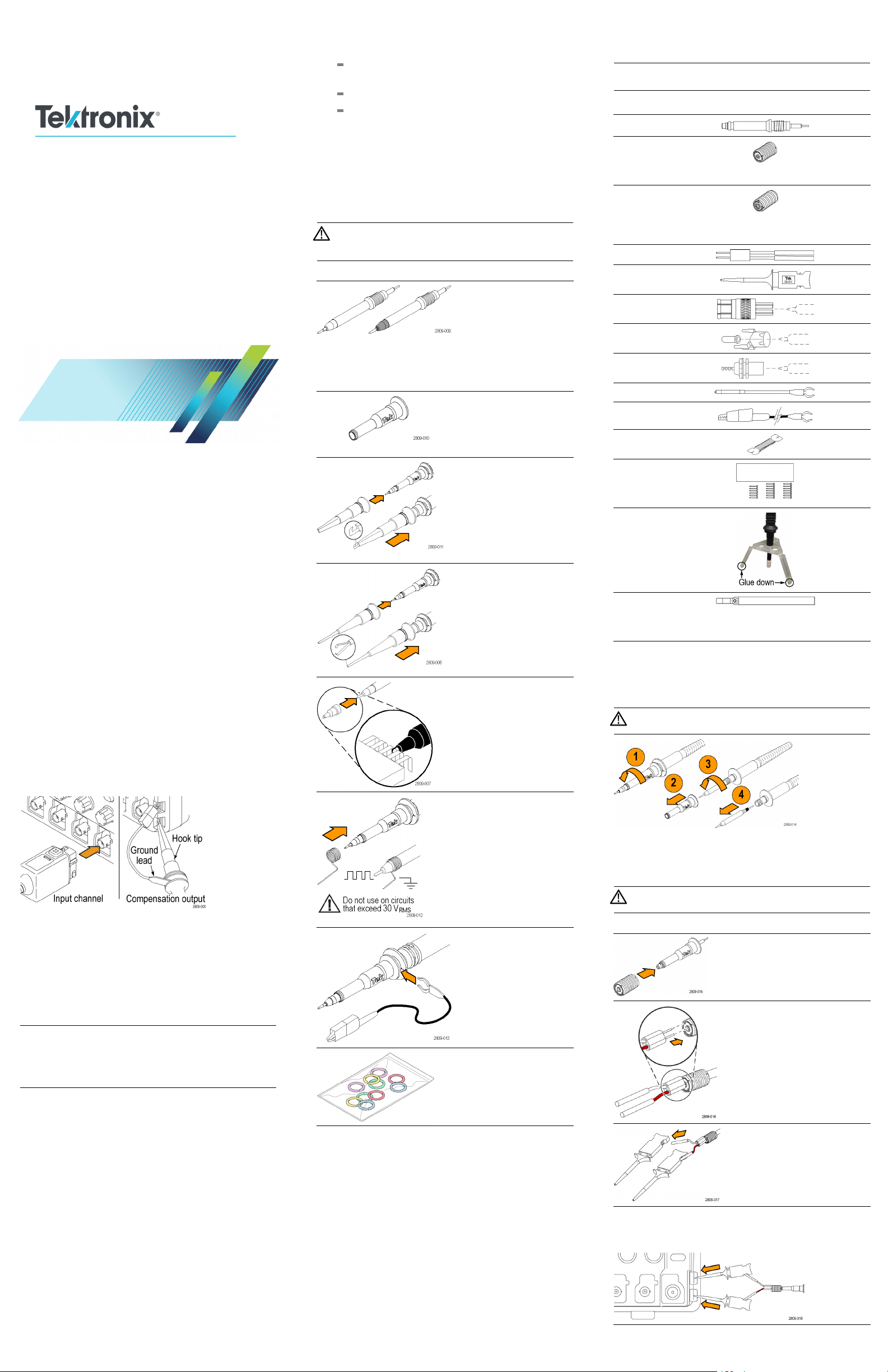
Operating information
The TPP1000 10X Passive Probe is a high impedance probe
with 10X attenuation that is designed for use with Tektronix
5 Series MSO and MDO3000, MDO/MSO/DPO4000B,
MSO/DPO5000 series ground-referenced oscilloscopes.
Connect the probe as shown in the illustrations below.
Comp
You should compensate the probe after you attach it to an
lloscope for the first time, or after you have changed the
osci
probe tip cartridge.
1. Connect the probe to an oscilloscope channel.
2. Connect the probe tip and ground to the probe
compensation terminals on the oscilloscope.
NOTE. When using the MMCX tip (206-0663-xx), the following
part numbers are required to connect the tip to the Probe
Comp connections: 131-9717-xx (1), 196-3434-xx (1),
and 206-0569-xx (2). See Connecting the MMCX tip to the
oscilloscope Probe Comp.
3. On 5 Series MSO instruments:
a. Doub
b. Select the Probe Setup.
c. Select Compensate Probe.
d. Sele
4. On MSO/DPO5000 instruments:
a. Select Vertical > Probe Cal....
b. Select the tab of the channel for the connected probe.
c. In the Calibration section, click Calibrate Probe.
ions
80903*
ensating the Probe
le tap the Channel Badge for the connected
probe.
ct Compensate Probe in the pop up window.
Item Description
Probe tips – pogo (white) and
rigid (gray)
The white pogo tip is
pre-installed on the probe, and
is spring-loaded for compliant
testing of circuit boards.
Reorder Tektronix part numbers:
206-0610-xx (rigid tip)
206-0611-xx (pogo tip)
Insulator sleeve
Unscrew this sleeve to replace
the probe tips.
Reorder Tektronix part number
342-1194-xx
Hook tip
Press the hook tip onto the probe
tip and then clamp the hook onto
the circuit.
Rating: 300 V CAT II
Reorder Tektronix part number
013-0362-xx
Micro hook tip
Use this tip to access test points
in tight spaces. Press the hook
tip onto the probe tip and then
extend the pincers around the
circuit.
Rating: 300 V CAT II
Reorder Tektronix part number
013-0363-xx
Universal IC cap
Use this cap to prevent shorting
the probe tip between IC pins.
Press the cap on the probe tip
until it snaps on, and then spin
o expose the probe tip
the cap t
toward the IC lead.
Reorder Tektronix part number
013-0366-xx
springs
Ground
To limit aberrations on high
frequency signals caused by
ground path inductance, bend
the spring to reach nearby
ground connections (<0.75 in,
0.25 in, short).
long; <
Reorder Tektronix part numbers:
016-2028-xx (long, 2 ea.)
016-2034-xx (short, 2 ea.)
Ground lead, with alligator clip
Secure the lead to the probe
head ground and then to your
circuit ground.
Reorder Tektronix part number
196-3521-xx
Color bands
Use these bands to identify the
oscilloscope channel at the probe
head.
Reorder Tektronix part number
016-0633-xx (5 pairs)
MicroCKT
Test T i p
BNC to Tip Adapter,
Unterminated
Circuit Board Test
Point/PCB Adapter
Chassis-Mount Probe
Test Jack
6” Clip-on Ground Lead
12” Alligator
Ground Lead
Wire, spool,
32 AWG
DUT Interface pin kit
with (qty. 20) 0.018 inch
(0.46 mm) round
solder-in pins
Probe tip tripod support
with living hinge, 2 each
Solder aid for 0.062-inch
(1.57 mm) pitch square
pins, 0.016 - 0.018-inch
(0.4 - 0.46 mm) sq. pins
1
See Connecting the MMCX tip to the oscilloscope Probe Comp for connection
instructions.
2
The tripod probe tip support is pictured with the probe tip and adapter attached.
changing the Probe Tip
Inter
2
206-0569-xx
013-0367-xx
016-2016-xx
131-4210-xx
196-3198-xx
196-3512-xx
020-3045-xx
020-3169-xx
352-1170-xx
003-1946-xx
WARNING. To reduce the risk of shock, disconnect the
before changing the probe tips.
probe
For optimal performance, do a probe compensation after the
tip has been replaced.
Connecting the MMCX tip to the oscilloscope Probe Comp
ING. To reduce the risk of shock, disconnect the
WARN
probe before connecting accessories.
Item Description
Connect the MMCX tip to
1
adapter
The MMCX adapter
(131-9717-xx) snaps onto
the MMCX tip.
Connect the Y–lead to MMCX
1
adapter
Push the Y–lead (196-3434-xx)
adapter into the MMCX adapter
until it is seated.
The signal input (red) connects
to the center of the MMCX
adapter.
Connect the MicroCKT test
tips to Y-lead
Push the Y-lead into the handles
of the MicroCKT test tips
(206-0569-xx).
Connect the MicroCKT test tips to Probe Comp terminals
Attach the two MicoCKT test tips to the Probe Comp terminals on the
ocsilloscope front panel.
1
MMCX tip, adapter, and Y-lead is limited to 30 vrms, 42 Vpk, 60 VDC, and
OVT <500 Vpk.
x
Page 2
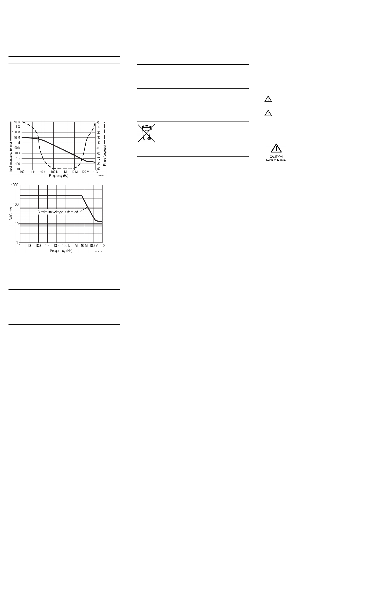
Electrical and mechanical specifications
Characteristic Specification
Bandwidth (–3 dB) 1 GHz
System rise time (typical)
System inpu
System attenuation accuracy 10:1 ±2.2%
Probe series resistance @DC 9.75 MΩ ±0.5%
System input resistance @DC 10 MΩ ±2%
Propagation delay ~5.67 ns
Maximum input voltage
Cable length
1
t capacitance
MMCX tip, adapter, and Y-lead is limited to 30 vrms, 42 Vpk, 60 VDC, and
OVT <500 Vpk.
<450 ps
Rigid and MM
Pogo pin tip: 5.1 pF ±0.5 pF
300 V
1.3 m ±3 cm
CX tip: 3.9 pF ±0.3 pF
1
CAT II
RMS
Performance graphs
Certifications and compliances
Characteristics Description
EU
Directives
Measuremen
Category
Product
Examples
Pollution
Degree 2
Additional
Safety
Standards
Compliance was demonstrated to the following
specification as listed in the Official Journal of the
European Communities:
Low Voltage
EN61010-031/A1: 2008
RoHS Directive 2011/65/EU
t
CAT III: Distribution-level mains, fixed installation
CAT II: Local-level mains, appliances, portable
equipment
CAT I: Circuits not directly connected to mains.
Do not operate in environments where conductive pollutants may be present (as defined in
IEC 61010-1). Rated for indoor use only.
UL61010-031;2010
CAN/CSA C22.2 No. 61010-031:07/A1:2010
IEC61010-031; IEC 61010-031/A1:2008
Equipment Recycling. This product complies
with the European Union’s requirements
according to Directive 2012/19/EU on waste
electrical and electronic equipment (WEEE). For
more information about recycling options, check
the Support/Service section of the Tektronix Web
site (www.tek.com/productrecycling).
Directive 2014/35/EU:
Avoid Exposed Circuitry a nd Do not Operate Without Covers. Do
not touch exposed connections and components when power
is present.
Inspect The Probe And Accessories. Before each use, inspect
probe and accessories for damage (cuts, tears, defects in the
probe body, accessories, cable jacket, etc.). Do not use if
damaged.
Do Not Operate in Wet/Damp Conditions.
Do Not Operate in an Explosive Atmosphere.
Keep Product Surfaces C lean and Dry.
Safety Terms and Symbols Terms in This Manual.
These terms may appear in this manual:
WARNING. Warning statements identify conditions or
practices that could result in injury or loss of life.
CAUTION. Caution statements identify conditions or
practices that could result in damage to this product or
other property.
Symbols on the Product. These symbols may appear on the
product:
onmental specifications
Envir
Characteristics Description
Temperature
Operating
perating
Nono
Humidity
Operating 5% to 95% relative humidity (%RH) up to
Nonoperating
Altitude
Operating
Nonoperating
–15°Cto+65°C(+5°Fto+149°F)
C to +85 °C (–80 °F to +185 °F)
–62 °
+30°C,5%to75%RHabove+30°Cupto
+65 °C. Noncondensing
5% to 45% RH above +65 °C up to +85 °C.
Noncondensing
3.0 km (9,842 ft) maximum
12.2 km (40,000 ft) maximum
Safety summary
Review the following safety precautions to avoid injury and
prevent damage to this product or any products connected to it.
To avoid potential hazards, use this product only as specified.
Using the probe or accessories in a manner not specified could
result in a shock or fire hazard.
To av oid fire or personal injury
Ground-Referenced Oscilloscope Use. Do not float the
reference lead of this probe when using with ground referenced
oscilloscopes (for example, MDO, MSO, and DPO series
oscilloscopes). The reference lead must be connected to earth
potential (0 V).
Connect and Discon nect Properly. Connect the probe output to
the measurement instrument before connecting the probe to the
circuit under test. Disconnect the probe input and the probe
reference lead from the circuit under test before disconnecting
the probe from the measurement instrument.
Avoid Electric Shock. To avoid injury or loss of life, do not
connect or disconnect probes or test leads while they are
connected to a voltage source.
Observe All Terminal Ratings. To avoid fi re or shock hazard,
observe all ratings and markings on the product. Consult the
product manual for further ratings information before making
connections to the product.
Avoid Electric Shock. When using probe accessories, never
exceed the lowest rating of the probe or its accessory, whichever
is less, including the measurement category and voltage rating.
Avoid Electric Overload. To avoid injury or fire hazard, do not
apply potential to any input, including the reference inputs,
that varies from ground by more than the maximum rating for
that input.
Contactin
Web site: www.tektronix.com
Phone: 1-800-833
Address: Tektronix, Inc.
Email:
g Tektronix
-9200
Department or name (if known)
14200 SW K
P.O . Box 5 0 0
Beaverton, OR 97077 USA
techsupport@tektronix.com
arl Braun Drive
Warranty information
For warranty information, go to http://www.tek.com/warranty.
Copyright © Tektronix, Inc. All rights reserved. www.tek.com
 Loading...