

Page 1

Instructions
TLA 7F1
TLA 700 Series Logic Analyzer DRAM and
Hard Disk Drive Upgrade Installation
070-9838-00
Warning
The servicing instructions are for use by qualified
personnel only. To avoid personal injury, do not
perform any servicing unless you are qualified to
do so. Refer to all safety summaries prior to
performing service.
Page 2

Copyright T ektronix, Inc. All rights reserved.
T ektronix products are covered by U.S. and foreign patents, issued and pending. Information in this publication supercedes
that in all previously published material. Specifications and price change privileges reserved.
Printed in the U.S.A.
T ektronix, Inc., P.O. Box 1000, Wilsonville, OR 97070–1000
TEKTRONIX and TEK are registered trademarks of T ektronix, Inc.
Page 3

Service Safety Summary
Only qualified personnel should perform service procedures. Read this Service
Safety Summary and the safety summaries in your product manual before
performing any service procedures.
Do Not Service Alone. Do not perform internal service or adjustments of this
product unless another person capable of rendering first aid and resuscitation is
present.
Disconnect Power. To avoid electric shock, disconnect the main power by means
of the power cord or, if provided, the power switch.
Use Care When Servicing With Power On. Dangerous voltages or currents may
exist in this product. Disconnect power, remove battery (if applicable), and
disconnect test leads before removing protective panels, soldering, or replacing
components.
To avoid electric shock, do not touch exposed connections.
TLA 700 Series DRAM and Hard Disk Drive Upgrade Installation
1
Page 4
Kit Description
This kit includes parts and instructions to upgrade the memory and hard disk
drive in the instrument.
Instruments
TLA 704 All Serial Numbers
TLA 711 All Serial Numbers
Minimum Tool and Equipment List
T able 1: Tools required for installing upgrade
Item
number
1 Torx-drive screwdriver with a T-9 tip Standard tool
2 Small flat-bladed screwdriver Standard tool
3 #0 Phillips screwdriver Standard tool
4 #1 Phillips screwdriver Standard tool
5 Diagonal cutters (to remove cable ties) Standard tool
6 Three-sixteenth (3/16) inch nut driver Standard tool
7 Needle nose plier Standard tool
8 Torx-drive screwdriver with a T-10 tip Standard tool
9 Torx-drive screwdriver with a T-15 tip Standard tool
Name Description
Kit Parts List
Quantity Part number Description
2 156-7503-00 16 MB SIMMs
1 119-5607-00 2.16 GB Hard Disk Drive
1 342-1027-00 Lexan Insulator
1 070-9838-00 TLA 7F1 Installation Instructions
1 TLA 7F1 Kit Label
1 TLA 7F1 Shipping List
TLA 700 Series DRAM and Hard Disk Drive Upgrade Installation
3
Page 5
Installation Instructions for the TLA 704 Color Portable Mainframe
These instructions direct you to replace the existing hard disk drive with a
greater capacity, but unformatted, hard disk drive. Prior to performing these
procedures, use the Windows 95 Back Up tool to back up any user files stored on
the hard disk drive. Use the backup media that was shipped with the instrument
to reinstall the operating system and applications. For further information on
software backup and installation, refer to the TLA 700 Series Logic Analyzer
Installation Manual.
NOTE. The following instructions are for upgrading the TLA 704 Color Portable
Mainframe. If you are upgrading a TLA 711 Color Benchtop Controller, proceed
to page 15.
These instructions assume that you are familiar with servicing the instrument. If
you need further details for disassembling or reassembling the instrument, refer
to the TLA 704 Color Portable Mainframe Service Manual. Contact your nearest
Tektronix, Inc., Service Center or Tektronix Factory Service Center for installation assistance.
CAUTION. To prevent static discharge damage, service the instrument only in a
static-free environment. Observe standard handling precautions for static-sensitive devices while installing this kit. Always wear a grounded wrist strap,
grounded foot strap, and static-resistant apparel while installing this kit.
These instructions must be performed in the sequence in which they are
presented; they include the following procedures:
H Disassembly, which removes the external parts needed to access the SIMM
boards and hard disk drive inside the portable mainframe.
H RAM SIMM Replacement, which removes the existing SIMM boards and
installs the upgrade SIMM boards.
H Hard Disk Drive Replacement, which removes the existing hard disk drive
and installs the upgrade hard disk drive.
H Reassembly, which reinstalls parts removed in Disassembly.
H Verify Operation, which reinstalls the software on the new hard disk drive
and runs some verification tests of the new memory and hard disk drive.
TLA 700 Series DRAM and Hard Disk Drive Upgrade Installation
5
Page 6

Installation Instructions
Disassembly
You will need a screwdriver with a size T-15 Torx tip to perform this procedure.
1. Disconnect the power cord from the mainframe.
2. Remove the modules and probes from the mainframe.
3. Set the mainframe on your work surface with the cord wrap feet facing down
and with the bottom facing you. (See Figure 1 on page 7.)
4. Remove the four screws that attach the bottom cover to the mainframe.
5. Lift the bottom cover off.
6. Grasp the front cover by its left and right edges and snap it off the front
panel. (See Figure 1 on page 7.)
7. Grasp the trim ring by its bottom edge and pull toward you to detach the
three plastic snaps. (Alternatively, you can use a flat-bladed screwdriver or
other small prying tool to help you detach the snaps.) Then, swing the
bottom of the ring upward and work the rest of the ring off the front panel.
6
TLA 700 Series DRAM and Hard Disk Drive Upgrade Installation
Page 7
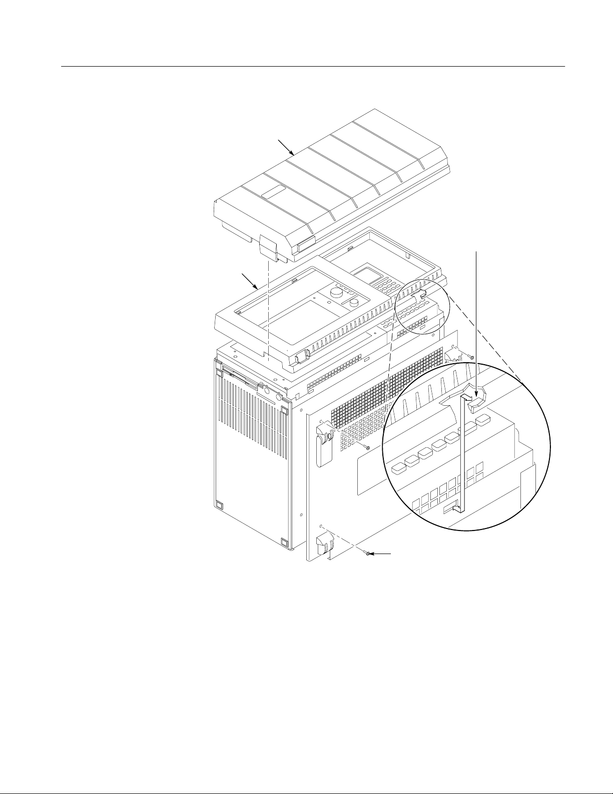
Trim ring
Installation Instructions
Cover
To remove the trim ring, grasp
its bottom edge and flex it
toward you before pulling
upward.
Figure 1: Front cover and trim ring removal
TLA 700 Series DRAM and Hard Disk Drive Upgrade Installation
Remove screws (4)
7
Page 8
Installation Instructions
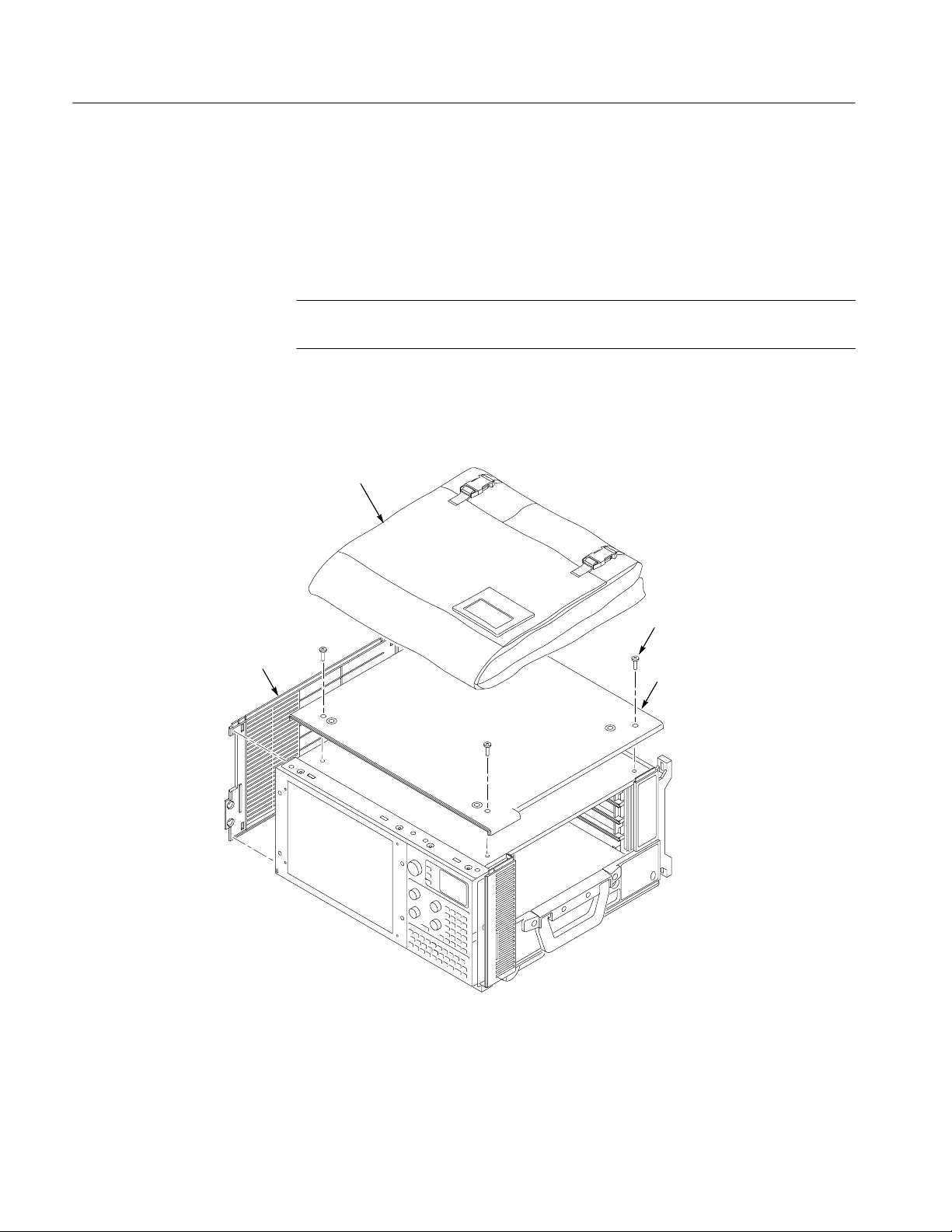
8. Set the mainframe on your work surface with the bottom facing down and
the front facing you. (See Figure 2.)
9. Remove the accessories pouch from the top cover. (It unsnaps.)
10. Remove the four screws that attach the top cover to the mainframe.
NOTE. Support the left side cover as you perform the following step. As you lift
off the top cover, the side cover will come free.
11. Lift the top cover off.
12. Remove the left side cover.
Accessories pouch
Left side
cover
Remove
screws (4)
Top cover
Figure 2: Pouch, top cover and left side cover removal
8
TLA 700 Series DRAM and Hard Disk Drive Upgrade Installation
Page 9

Installation Instructions
13. Remove the five screws that attach the flat panel display assembly to the
mainframe. (See Figure 3.)
14. Lift the bottom edge of the flat panel display assembly and rotate it upward
and off the front face of the mainframe.
15. Detach the cable connecting the flat panel display assembly to the interface
board.
Remove screws (5)
Figure 3: Flat panel display assembly removal
TLA 700 Series DRAM and Hard Disk Drive Upgrade Installation
Disconnect
the cable
Flat panel display
assembly
9
Page 10

Installation Instructions
RAM SIMMs Replacement
You will need a screwdriver with a size T-15 Torx tip to perform this procedure.
Removal
Installation
Use the following procedure to remove the RAM SIMMs:
1. Set the mainframe on your work surface with the bottom facing down and
with the left side facing you.
2. Remove the eight screws securing the EMI shield to the chassis and lift off
the EMI shield.
3. Locate the SIMM boards in Figure 4 on page 11. Note that there are two
SIMM boards, an upper and a lower.
4. Press outward on the clips holding each SIMM board to the controller board
and lift off the SIMM board. Remove both boards.
Use the following procedure to install the new SIMM boards:
NOTE. When installing the SIMM boards, make sure that both SIMM boards
contain RAM memory of the same size.
1. Install the new SIMM boards. Press down gently until the clips that hold the
SIMM boards to the controller board snap into place.
2. Reposition the EMI shield and install the eight screws that secure it to the
chassis.
10
TLA 700 Series DRAM and Hard Disk Drive Upgrade Installation
Page 11

Press
outward
Installation Instructions
Press
outward
Press
outward
SIMM boards (2)
Press
outward
Hard disk
drive,
bracket
Figure 4: SIMM boards and hard disk drive replacement
TLA 700 Series DRAM and Hard Disk Drive Upgrade Installation
11
Page 12

Installation Instructions
Hard Disk Drive Replacement
You will need screwdrivers with a size T-15 Torx tip and a size T-10 Torx tip to
perform this procedure.
Removal
Installation
Use the following procedure to remove the hard disk drive:
1. Locate the hard disk drive in Figure 4 on page 11.
2. Detach the cable at the bottom of the hard disk drive by pressing down
(away from the hard disk drive) on the connector.
3. Remove the four screws that attach the hard disk drive bracket to the chassis.
4. Lift the hard disk drive and bracket out of the chassis.
5. Remove the four screws that attach the hard disk drive to the bracket.
6. Lift out the hard disk drive.
Use the following procedure to install the hard disk drive:
1. Reposition the hard disk drive in the bracket.
2. Install the four screws that attach the hard disk drive to the bracket.
3. Reposition the hard disk drive and bracket in the chassis.
4. Install the four screws that attach the hard disk drive bracket to the chassis.
5. Reattach the cable at the bottom of the hard disk drive by carefully aligning
the pins on the hard disk drive to the cable connector.
Reassembly
12
6. Gently press the cable connector into the bottom of the hard disk drive.
Use the following procedure to reassemble the instrument:
1. Reattach the cable connecting the flat panel display assembly to the interface
board.
2. Reinstall the flat panel display assembly by first inserting the top edge and
then rotating it downward into position. (Be sure the tabs are engaged at the
top of the assembly.)
3. Install the five screws that attach the flat panel display assembly to the
mainframe. (See Figure 3 on page 9.)
TLA 700 Series DRAM and Hard Disk Drive Upgrade Installation
Page 13

Installation Instructions
4. Reposition the left side cover.
5. Reposition the top cover on the portable mainframe.
6. Install the four screws that attach the top cover to the mainframe.
7. Reattach the accessories pouch to the top cover. (It snaps on.)
8. Replace the trim ring on the front panel. Start at the top edge and work
around to the bottom (using care not to damage the light pipe or power
switch), until the three plastic snaps engage. Press the trim ring down all
around the edges until it is completely seated.
9. Press the front cover back onto the front panel until the left and right edges
snap into place.
10. Reposition the bottom cover on the portable mainframe.
11. Install the four screws that attach the bottom cover to the mainframe.
12. Reinstall the modules and probes that were removed during dissassembly.
Verify Operation
13. Connect the power cord to the mainframe.
Follow the steps below to ensure proper operation of the instrument:
1. Reinstall all software. For help on software installation, refer to the
TLA 700 Series Logic Analyzer Installation Manual.
2. Run memory and hard disk drive verification tests from the QAPlus
diagnostics.
NOTE. You must have Windows 95 running to run QAPlus.
a. Turn off all other applications.
b. Click Start in the Windows 95 tool bar.
c. Select Programs from the Start menu.
d. Select the QAPlus application from the Programs menu.
e. Run the memory and hard disk drive tests from the QAPlus menu. If
needed, refer to the QAPlus online help for more information on running
QAPlus.
TLA 700 Series DRAM and Hard Disk Drive Upgrade Installation
13
Page 14

Installation Instructions for the TLA 711 Color Benchtop Controller
These instructions direct you to replace the existing hard disk drive with a
greater capacity, but unformatted, hard disk drive. Prior to performing these
procedures, use the Windows 95 Back Up tool to back up any user files stored on
the hard disk drive. Use the backup media that was shipped with the instrument
to reinstall the operating system and applications. For further information on
software backup and installation, refer to the TLA 700 Series Logic Analyzer
Installation Manual.
NOTE. The following instructions are for upgrading the TLA 711 Color Benchtop
Controller. If you are upgrading a TLA 704 Color Portable Mainframe, proceed
to page 5. Otherwise, please read the following paragraph closely.
These instructions require you to be familiar with servicing the instrument,
because of the complexity of the Controller subassembly. If you are not familiar
with servicing the instrument, it is strongly recommended that you contact your
nearest Tektronix, Inc., Service Center or Tektronix Factory Service for
installation.
CAUTION. To prevent static discharge damage, service the instrument only in a
static-free environment. Observe standard handling precautions for static-sensitive devices while installing this kit. Always wear a grounded wrist strap,
grounded foot strap, and static-resistant apparel while installing this kit.
These instructions must be performed in the sequence in which they are
presented; they include the following procedures:
H Disassembly, which removes the external parts needed to remove the
Controller subassembly from its enclosure to access the SIMM boards and
hard disk drive.
H RAM SIMM Replacement, which removes the existing SIMM boards and
installs the upgrade SIMM boards.
H Hard Disk Drive Replacement, which removes the existing hard disk drive
and installs the upgrade hard disk drive.
H Reassembly, which reinstalls parts removed in Disassembly.
H Verify Operation, which reinstalls the software on the new hard disk drive
and runs some verification tests of the new memory and hard disk drive.
TLA 700 Series DRAM and Hard Disk Drive Upgrade Installation
15
Page 15

Installation Instructions
Disassembly
Verify that the power cord has been disconnected from the mainframe. Remove
any connected cables or probes from the benchtop controller and remove the
benchtop controller from the mainframe.
You will need a T-9 Torx tip driver to remove the left side cover and rear panel.
1. Place the module on its right side as shown in Figure 5.
2. Remove the six screws from the top and bottom of the left side cover.
3. Remove the two screws from the rear panel. (See Figure 5.)
4. Remove the rear panel.
5. Remove the left side cover.
Remove screws (6)
Left side cover
Chassis
16
Remove screws (2)
Rear panel
Figure 5: Left side cover and rear panel removal
TLA 700 Series DRAM and Hard Disk Drive Upgrade Installation
Page 16

Installation Instructions
You will need a T-9 Torx tip driver, a small flat-bladed screwdriver, a #0 Phillips
screwdriver, a #1 Phillips screwdriver, a 3/16 inch nut driver, and a needle nose
plier to remove the Controller subassembly.
NOTE. The following steps remove the subassembly from the enclosure to gain
access to the internal parts. Note that subassembly removal is a two part
procedure: first you will remove the front panel hardware to relieve mechanical
stress on the soldered-on connectors. Second, you will remove the subassembly
from the enclosure.
6. Remove the four 3/16 inch standoffs from the SVGA OUT and COM
connectors. (See Figure 6.)
7. Remove the two screws from the LPT connector.
8. Remove the two Phillips screws, located to the right of the PC card slot.
9. DO NOT remove the 1/4 inch nuts on the SMB connectors.
Remove
screws (2)
Remove standoffs (4)
Figure 6: Front panel hardware removal
10. Remove the six Phillips screws that attach the subassembly to the chassis.
(See figure 7.)
TLA 700 Series DRAM and Hard Disk Drive Upgrade Installation
Remove screws (2)
17
Page 17

Installation Instructions
Remove screws (6)
Chassis
Figure 7: Subassembly removal
CAUTION. The subassembly is attached to the chassis by the four SMB connector
cable assemblies. To avoid damaging the subassembly, use care when lifting the
subassembly out.
11. Carefully lift the subassembly part way out of the chassis.
12. Carefully turn the subassembly over and disconnect the four SMB cable
assemblies on the Controller board. See Figure 9 and Table 2 for the color
code placement of the four SMB cable assemblies.
13. Pass the SMB cable assemblies through the space between the Controller
board and the Adapter board to remove the subassembly from the chassis.
18
TLA 700 Series DRAM and Hard Disk Drive Upgrade Installation
Page 18

RAM SIMMs Replacement
The RAM SIMMs are located on the Controller board of the subassembly that
you just removed. (See Figure 8.) Removal and installation of the SIMM boards
do not require the use of tools.
Removal
1. Press outward on the clips holding each SIMM board to the Controller board
Installation Instructions
and lift off the SIMM board. Remove both boards. (See Figure 8.)
Installation
Controller board
Figure 8: SIMM boards removal
NOTE. When installing the SIMM boards, make sure that both SIMM boards
contain RAM memory of the same size.
SIMM boards
1. Align the SIMM board with the socket and gently push the SIMM board into
the socket.
2. The tabs on each side of the SIMM board will engage and lock the SIMM
board into place. Install both SIMM boards.
TLA 700 Series DRAM and Hard Disk Drive Upgrade Installation
19
Page 19

Installation Instructions
Hard Disk Drive Replacement
You will need a #0 Phillips screwdriver and a #1 Phillips screwdriver.
Removal
The hard disk drive is mounted to the Adapter board, which must be separated
from the Controller board in order to replace the hard disk drive. Refer to
Figure 9 and follow these steps:
1. Disconnect the two ribbon cables from the component side of the Controller
board. Note the location of the ribbon cables for reassembly.
2. Remove the five Phillips screws that attach the Controller board to the
Adapter board.
3. Squeeze the two sides of the standoff located in the center of the Controller
board to unlatch the standoff while separating the two boards. You might feel
some mechanical resistance from the two 96-pin interconnections between
the two boards.
20
TLA 700 Series DRAM and Hard Disk Drive Upgrade Installation
Page 20

Installation Instructions
Squeeze to
remove
Disconnect
SMB cable
assemblies (4)
Remove screws (5)
Controller board
Brown
Orange
Red
White
Figure 9: Controller board and Adapter board interconnection
4. Remove the four Phillips screws securing the hard disk drive to the solder
side of the Adapter board. (See Figure 10.)
5. Carefully slide the hard disk drive away from the hard disk drive connector.
TLA 700 Series DRAM and Hard Disk Drive Upgrade Installation
Disconnect ribbon
cables (2)
Center standoff
Adapter board
21
Page 21

Installation Instructions
Hard disk drive
Installation
Remove screws (4)
Figure 10: Hard disk drive removal
To install the hard disk drive you will need a #0 Phillips screwdriver and a #1
Phillips screwdriver.
1. Peel the backing off of the Lexan insulator included in the kit and apply it to
the hard disk drive. (See Figure 11.)
22
TLA 700 Series DRAM and Hard Disk Drive Upgrade Installation
Page 22

Lexan insulator
Hard disk drive
Pins
Figure 11: Applying the Lexan insulator
Installation Instructions
Align with edge
Reassembly
2. Carefully align the connector pins on the back of the hard disk drive to the
socket on the Adapter board. Gently slide the hard disk drive into the socket.
Verify that all of the pins are fully engaged and that no pins are bent.
3. Install the four screws to secure the hard disk drive to the Adapter board.
4. Connect the Controller board to the Adapter board by aligning the two
connectors between the Controller board and the Adapter board. Locate the
center standoff (see Figure 9 on page 21) and center it on the hole on the
Controller board. Carefully apply pressure to both boards until the two
connectors engage.
5. Connect the two ribbon cables to the component side of the Controller board.
Note the location of the ribbon cables from the disassembly procedure,
step 1.
6. Install the five screws to secure the Controller board to the Adapter board.
To install the subassembly into the enclosure refer to Figures 6 and 7 as you
follow these steps:
1. Pass the four SMB cable assemblies through the space between the
Controller board and the Adapter board.
TLA 700 Series DRAM and Hard Disk Drive Upgrade Installation
23
Page 23

Installation Instructions
2. Carefully turn the subassembly over and connect the four SMB cable
assemblies to the four SMB connectors on the Controller board. Figure 9 on
page 21 shows the locations for plugging in the four connectors. Table 2
identifies each connector by color code and signal name.
T able 2: Signal wire identification
Signal wire color Signal identification
White SYSTEM TRIG IN
White / Brown stripe SYSTEM TRIG OUT
White / Red stripe EXTERNAL SIG IN
White / Orange stripe EXTERNAL SIG OUT
3. Carefully slide the subassembly into the chassis. Locate all of the front panel
connectors into the proper cut-outs on the front panel.
Verify Operation
4. Attach the six Phillips screws that hold the subassembly to the chassis. DO
NOT tighten the screws until the front panel hardware has been secured.
5. Install the two screws located to the right of the PC card slot.
6. Install the four standoffs on the SVGA OUT and COM connectors.
7. Install the two screws on the LPT connector.
8. Tighten the six screws that secure the subassembly to the chassis.
9. Install the module in the mainframe and connect any cables that were
removed during dissassembly, including the power cord.
Follow the steps below to ensure proper operation of the instrument:
1. Reinstall all software. For help on software installation, refer to the
TLA 700 Series Logic Analyzer Installation Manual.
2. Run memory and hard disk drive verification tests from the QAPlus
diagnostics.
24
NOTE. To run QAPlus you must have either a working keyboard or working
mouse (or other pointing device) and Windows 95 running.
a. Turn off all other applications.
TLA 700 Series DRAM and Hard Disk Drive Upgrade Installation
Page 24

Installation Instructions
b. Click Start in the Windows 95 tool bar.
c. Select Programs from the Start menu.
d. Select the QAPlus application from the Programs menu.
e. Run the memory and hard disk drive tests from the QAPlus menu. If
needed, refer to the QAPlus online help for more information on running
QAPlus.
TLA 700 Series DRAM and Hard Disk Drive Upgrade Installation
25
 Loading...