

Page 1

Service Manual
TLA 720
Color Benchtop Chassis and
TLA 7XM
Expansion Chassis
071-0699-00
Warning
The servicing instructions are for use by qualified
personnel only. To avoid personal injury, do not
perform any servicing unless you are qualified to
do so. Refer to all safety summaries prior to
performing service.
Page 2

Copyright © T ektronix, Inc. All rights reserved.
T ektronix products are covered by U.S. and foreign patents, issued and pending. Information in this publication supercedes
that in all previously published material. Specifications and price change privileges reserved.
T ektronix, Inc., 14200 SW Karl Braun Drive, Beaverton, OR 97077
TEKTRONIX and TEK are registered trademarks of T ektronix, Inc.
Page 3

HARDWARE WARRANTY
T ektronix warrants that the products that it manufactures and sells will be free from defects in materials and workmanship
for a period of one (1) year from the date of shipment. If a product proves defective during this warranty period, T ektronix,
at its option, either will repair the defective product without charge for parts and labor, or will provide a replacement in
exchange for the defective product.
In order to obtain service under this warranty, Customer must notify Tektronix of the defect before the expiration of the
warranty period and make suitable arrangements for the performance of service. Customer shall be responsible for
packaging and shipping the defective product to the service center designated by T ektronix, with shipping charges prepaid.
T ektronix shall pay for the return of the product to Customer if the shipment is to a location within the country in which the
T ektronix service center is located. Customer shall be responsible for paying all shipping charges, duties, taxes, and any
other charges for products returned to any other locations.
This warranty shall not apply to any defect, failure or damage caused by improper use or improper or inadequate
maintenance and care. T ektronix shall not be obligated to furnish service under this warranty a) to repair damage resulting
from attempts by personnel other than T ektronix representatives to install, repair or service the product; b) to repair
damage resulting from improper use or connection to incompatible equipment; c) to repair any damage or malfunction
caused by the use of non-T ektronix supplies; or d) to service a product that has been modified or integrated with other
products when the effect of such modification or integration increases the time or difficulty of servicing the product.
THIS WARRANTY IS GIVEN BY TEKTRONIX IN LIEU OF ANY OTHER WARRANTIES, EXPRESS OR
IMPLIED. TEKTRONIX AND ITS VENDORS DISCLAIM ANY IMPLIED WARRANTIES OF
MERCHANTABILITY OR FITNESS FOR A PARTICULAR PURPOSE. TEKTRONIX’ RESPONSIBILITY TO
REP AIR OR REPLACE DEFECTIVE PRODUCTS IS THE SOLE AND EXCLUSIVE REMEDY PROVIDED TO
THE CUSTOMER FOR BREACH OF THIS WARRANTY. TEKTRONIX AND ITS VENDORS WILL NOT BE
LIABLE FOR ANY INDIRECT , SPECIAL, INCIDENTAL, OR CONSEQUENTIAL DAMAGES IRRESPECTIVE
OF WHETHER TEKTRONIX OR THE VENDOR HAS ADVANCE NOTICE OF THE POSSIBILITY OF SUCH
DAMAGES.
Page 4

SOFTWARE WARRANTY
T ektronix warrants that the media on which this software product is furnished and the encoding of the programs on the
media will be free from defects in materials and workmanship for a period of three (3) months from the date of shipment.
If a medium or encoding proves defective during the warranty period, T ektronix will provide a replacement in exchange
for the defective medium. Except as to the media on which this software product is furnished, this software product is
provided “as is” without warranty of any kind, either express or implied. T ektronix does not warrant that the functions
contained in this software product will meet Customer’s requirements or that the operation of the programs will be
uninterrupted or error-free.
In order to obtain service under this warranty, Customer must notify Tektronix of the defect before the expiration of the
warranty period. If T ektronix is unable to provide a replacement that is free from defects in materials and workmanship
within a reasonable time thereafter, Customer may terminate the license for this software product and return this software
product and any associated materials for credit or refund.
THIS WARRANTY IS GIVEN BY TEKTRONIX IN LIEU OF ANY OTHER WARRANTIES, EXPRESS OR
IMPLIED. TEKTRONIX AND ITS VENDORS DISCLAIM ANY IMPLIED WARRANTIES OF
MERCHANTABILITY OR FITNESS FOR A PARTICULAR PURPOSE. TEKTRONIX’ RESPONSIBILITY TO
REPLACE DEFECTIVE MEDIA OR REFUND CUSTOMER’S PAYMENT IS THE SOLE AND EXCLUSIVE
REMEDY PROVIDED TO THE CUSTOMER FOR BREACH OF THIS WARRANTY. TEKTRONIX AND ITS
VENDORS WILL NOT BE LIABLE FOR ANY INDIRECT , SPECIAL, INCIDENTAL, OR CONSEQUENTIAL
DAMAGES IRRESPECTIVE OF WHETHER TEKTRONIX OR THE VENDOR HAS ADVANCE NOTICE OF
THE POSSIBILITY OF SUCH DAMAGES.
Page 5

Table of Contents
Specifications
Operating Information
General Safety Summary ix. . . . . . . . . . . . . . . . . . . . . . . . . . . . . . . . . . . .
Service Safety Summary xi. . . . . . . . . . . . . . . . . . . . . . . . . . . . . . . . . . . . .
Preface xiii. . . . . . . . . . . . . . . . . . . . . . . . . . . . . . . . . . . . . . . . . . . . . . . . . . .
Manual Structure xiii. . . . . . . . . . . . . . . . . . . . . . . . . . . . . . . . . . . . . . . . . . . . . . . . .
Manual Conventions xiii. . . . . . . . . . . . . . . . . . . . . . . . . . . . . . . . . . . . . . . . . . . . . .
Contacting T ektronix xiv. . . . . . . . . . . . . . . . . . . . . . . . . . . . . . . . . . . . . . . . . . . . . .
Introduction xv. . . . . . . . . . . . . . . . . . . . . . . . . . . . . . . . . . . . . . . . . . . . . . .
Adjustment Interval xv. . . . . . . . . . . . . . . . . . . . . . . . . . . . . . . . . . . . . . . . . . . . . . .
Strategy for Servicing xv. . . . . . . . . . . . . . . . . . . . . . . . . . . . . . . . . . . . . . . . . . . . .
Service Offerings xvi. . . . . . . . . . . . . . . . . . . . . . . . . . . . . . . . . . . . . . . . . . . . . . . . .
Benchtop Chassis Specifications 1–1. . . . . . . . . . . . . . . . . . . . . . . . . . . . . .
Product Description 1–1. . . . . . . . . . . . . . . . . . . . . . . . . . . . . . . . . . . . . . . . . . . . . . .
Characteristics T ables 1–3. . . . . . . . . . . . . . . . . . . . . . . . . . . . . . . . . . . . . . . . . . . . . .
Expansion Chassis Specifications 1–9. . . . . . . . . . . . . . . . . . . . . . . . . . . . . .
Product Description 1–9. . . . . . . . . . . . . . . . . . . . . . . . . . . . . . . . . . . . . . . . . . . . . . .
Characteristics T ables 1–10. . . . . . . . . . . . . . . . . . . . . . . . . . . . . . . . . . . . . . . . . . . . . .
Selecting the Correct Power Cord and Fuse 2–5. . . . . . . . . . . . . . . . . . . . . . . . . . . .
Reference 2–7. . . . . . . . . . . . . . . . . . . . . . . . . . . . . . . . . . . . . . . . . . . . . . . . .
Passive Monitor Connector 2–7. . . . . . . . . . . . . . . . . . . . . . . . . . . . . . . . . . . . . . . . .
Enhanced Monitor RS-232 Connector 2–11. . . . . . . . . . . . . . . . . . . . . . . . . . . . . . . . .
Backplane Connectors 2–12. . . . . . . . . . . . . . . . . . . . . . . . . . . . . . . . . . . . . . . . . . . . .
Enhanced Monitor 2–16. . . . . . . . . . . . . . . . . . . . . . . . . . . . . . . . . . . . . . . . . . . . . . . .
Syntax 2–19. . . . . . . . . . . . . . . . . . . . . . . . . . . . . . . . . . . . . . . . . . . . . . . . . . . .
SCPI 2–19. . . . . . . . . . . . . . . . . . . . . . . . . . . . . . . . . . . . . . . . . . . . . . . . . . . . . . . . . . .
Command Syntax 2–19. . . . . . . . . . . . . . . . . . . . . . . . . . . . . . . . . . . . . . . . . . . . . . . . .
Entering Commands 2–23. . . . . . . . . . . . . . . . . . . . . . . . . . . . . . . . . . . . . . . . . . . . . . .
Command Groups 2–25. . . . . . . . . . . . . . . . . . . . . . . . . . . . . . . . . . . . . . . . . .
Status Commands 2–25. . . . . . . . . . . . . . . . . . . . . . . . . . . . . . . . . . . . . . . . . . . . . . . . .
System Commands 2–27. . . . . . . . . . . . . . . . . . . . . . . . . . . . . . . . . . . . . . . . . . . . . . . .
T est Commands 2–29. . . . . . . . . . . . . . . . . . . . . . . . . . . . . . . . . . . . . . . . . . . . . . . . . .
TEST Subsystem 2–67. . . . . . . . . . . . . . . . . . . . . . . . . . . . . . . . . . . . . . . . . . .
TEST? 2–68. . . . . . . . . . . . . . . . . . . . . . . . . . . . . . . . . . . . . . . . . . . . . . . . . . . . . . . . .
TEST:NUMBer? 2–69. . . . . . . . . . . . . . . . . . . . . . . . . . . . . . . . . . . . . . . . . . . . . . . . .
TEST:RESults? 2–70. . . . . . . . . . . . . . . . . . . . . . . . . . . . . . . . . . . . . . . . . . . . . . . . . .
TEST:RESults:VERBose? 2–71. . . . . . . . . . . . . . . . . . . . . . . . . . . . . . . . . . . . . . . . . .
TLA 720 Benchtop Chassis and TLA 7XM Expansion Chassis Service Manual
i
Page 6

Table of Contents
Theory of Operation
Maintenance
IEEE 488.2 Common Commands 2–73. . . . . . . . . . . . . . . . . . . . . . . . . . . . .
*CLS 2–74. . . . . . . . . . . . . . . . . . . . . . . . . . . . . . . . . . . . . . . . . . . . . . . . . . . . . . . . . .
*ESE? 2–75. . . . . . . . . . . . . . . . . . . . . . . . . . . . . . . . . . . . . . . . . . . . . . . . . . . . . . . . . .
*ESR? 2–76. . . . . . . . . . . . . . . . . . . . . . . . . . . . . . . . . . . . . . . . . . . . . . . . . . . . . . . . . .
*IDN? 2–77. . . . . . . . . . . . . . . . . . . . . . . . . . . . . . . . . . . . . . . . . . . . . . . . . . . . . . . . . .
*OPC? 2–78. . . . . . . . . . . . . . . . . . . . . . . . . . . . . . . . . . . . . . . . . . . . . . . . . . . . . . . . .
*PSC? 2–79. . . . . . . . . . . . . . . . . . . . . . . . . . . . . . . . . . . . . . . . . . . . . . . . . . . . . . . . . .
*RST 2–80. . . . . . . . . . . . . . . . . . . . . . . . . . . . . . . . . . . . . . . . . . . . . . . . . . . . . . . . . .
*SRE? 2–81. . . . . . . . . . . . . . . . . . . . . . . . . . . . . . . . . . . . . . . . . . . . . . . . . . . . . . . . . .
*STB? 2–82. . . . . . . . . . . . . . . . . . . . . . . . . . . . . . . . . . . . . . . . . . . . . . . . . . . . . . . . . .
*TST? 2–83. . . . . . . . . . . . . . . . . . . . . . . . . . . . . . . . . . . . . . . . . . . . . . . . . . . . . . . . . .
*WAI 2–84. . . . . . . . . . . . . . . . . . . . . . . . . . . . . . . . . . . . . . . . . . . . . . . . . . . . . . . . . .
Benchtop Chassis 3–1. . . . . . . . . . . . . . . . . . . . . . . . . . . . . . . . . . . . . . . . . . . . . . . . .
Preparation 4–1. . . . . . . . . . . . . . . . . . . . . . . . . . . . . . . . . . . . . . . . . . . . . . . . . . . . . .
Preventing ESD 4–1. . . . . . . . . . . . . . . . . . . . . . . . . . . . . . . . . . . . . . . . . . . . . . . . . .
Inspection and Cleaning 4–2. . . . . . . . . . . . . . . . . . . . . . . . . . . . . . . . . . . . . . . . . . . .
Removal and Installation Procedures 4–3. . . . . . . . . . . . . . . . . . . . . . . . . .
Preparation 4–3. . . . . . . . . . . . . . . . . . . . . . . . . . . . . . . . . . . . . . . . . . . . . . . . . . . . . .
T ools Required 4–3. . . . . . . . . . . . . . . . . . . . . . . . . . . . . . . . . . . . . . . . . . . . . . . . . . .
Install Empty Slot Panel Fillers 4–4. . . . . . . . . . . . . . . . . . . . . . . . . . . . . . . . . . . . . .
Module Removal and Replacement 4–5. . . . . . . . . . . . . . . . . . . . . . . . . . . . . . . . . . .
Removing the Blower Assembly 4–5. . . . . . . . . . . . . . . . . . . . . . . . . . . . . . . . . . . . .
Removing the Enhanced Monitor Board 4–8. . . . . . . . . . . . . . . . . . . . . . . . . . . . . . .
Removing the Power Supply 4–9. . . . . . . . . . . . . . . . . . . . . . . . . . . . . . . . . . . . . . . .
Removing the Mainframe Cover 4–10. . . . . . . . . . . . . . . . . . . . . . . . . . . . . . . . . . . . .
Removing the Card Guides 4–11. . . . . . . . . . . . . . . . . . . . . . . . . . . . . . . . . . . . . . . . .
Removing the Nut Rails 4–13. . . . . . . . . . . . . . . . . . . . . . . . . . . . . . . . . . . . . . . . . . . .
Removing the T emperature Sense Board 4–14. . . . . . . . . . . . . . . . . . . . . . . . . . . . . . .
Removing the EMI DIN Shields 4–15. . . . . . . . . . . . . . . . . . . . . . . . . . . . . . . . . . . . .
Removing the Backplane 4–16. . . . . . . . . . . . . . . . . . . . . . . . . . . . . . . . . . . . . . . . . . .
Special Configuration Options 4–18. . . . . . . . . . . . . . . . . . . . . . . . . . . . . . . . . . . . . . .
Jumper Settings 4–21. . . . . . . . . . . . . . . . . . . . . . . . . . . . . . . . . . . . . . . . . . . .
Backplane Jumpers 4–21. . . . . . . . . . . . . . . . . . . . . . . . . . . . . . . . . . . . . . . . . . . . . . . .
Enhanced Monitor Board Jumpers 4–23. . . . . . . . . . . . . . . . . . . . . . . . . . . . . . . . . . . .
Enhanced Monitor Board Flash Jumper 4–24. . . . . . . . . . . . . . . . . . . . . . . . . . . . . . . .
Enhanced Monitor Board Logical Address Switch Settings 4–25. . . . . . . . . . . . . . . .
Hardware Troubleshooting 4–27. . . . . . . . . . . . . . . . . . . . . . . . . . . . . . . . . . .
Service Level 4–27. . . . . . . . . . . . . . . . . . . . . . . . . . . . . . . . . . . . . . . . . . . . . . . . . . . .
Check for Common Problems 4–28. . . . . . . . . . . . . . . . . . . . . . . . . . . . . . . . . . . . . . .
Troubleshoot the Benchtop Chassis 4–29. . . . . . . . . . . . . . . . . . . . . . . . . . . . . . . . . . .
Overview of Procedures 4–30. . . . . . . . . . . . . . . . . . . . . . . . . . . . . . . . . . . . . . . . . . . .
Mainframe Troubleshooting 4–35. . . . . . . . . . . . . . . . . . . . . . . . . . . . . . . . . .
Diagnostics 4–35. . . . . . . . . . . . . . . . . . . . . . . . . . . . . . . . . . . . . . . . . . . . . . . . . . . . . .
Software Problems 4–36. . . . . . . . . . . . . . . . . . . . . . . . . . . . . . . . . . . . . . . . . . . . . . . .
Hardware Problems 4–36. . . . . . . . . . . . . . . . . . . . . . . . . . . . . . . . . . . . . . . . . . . . . . .
ii
TLA 720 Benchtop Chassis and TLA 7XM Expansion Chassis Service Manual
Page 7

Check for Common Problems 4–37. . . . . . . . . . . . . . . . . . . . . . . . . . . . . . . . . . . . . . .
TLA 700 Startup Sequence 4–40. . . . . . . . . . . . . . . . . . . . . . . . . . . . . . . . . . . . . . . . .
Isolating System Problems 4–42. . . . . . . . . . . . . . . . . . . . . . . . . . . . . . . . . . . . . . . .
Expansion Mainframe Troubleshooting 4–44. . . . . . . . . . . . . . . . . . . . . . . . . . . . . . . .
Repackaging Instructions 4–47. . . . . . . . . . . . . . . . . . . . . . . . . . . . . . . . . . . .
Packaging 4–47. . . . . . . . . . . . . . . . . . . . . . . . . . . . . . . . . . . . . . . . . . . . . . . . . . . . . . .
Shipping to the Service Center 4–47. . . . . . . . . . . . . . . . . . . . . . . . . . . . . . . . . . . . . . .
Options
Service Options 5–1. . . . . . . . . . . . . . . . . . . . . . . . . . . . . . . . . . . . . . . . . . . . . . . . . .
Diagrams
Replaceable Mechanical Parts
Standard Accessories 7–1. . . . . . . . . . . . . . . . . . . . . . . . . . . . . . . . . . . . . . . . . . . . . .
Optional Accessories 7–2. . . . . . . . . . . . . . . . . . . . . . . . . . . . . . . . . . . . . . . . . . . . . .
Parts Ordering Information 7–2. . . . . . . . . . . . . . . . . . . . . . . . . . . . . . . . . . . . . . . . .
Using the Replaceable Parts List 7–3. . . . . . . . . . . . . . . . . . . . . . . . . . . . . . . . . . . . .
Table of Contents
Index
TLA 720 Benchtop Chassis and TLA 7XM Expansion Chassis Service Manual
iii
Page 8

Table of Contents
List of Figures
Figure 1–1: Front and side view of the benchtop chassis 1–7. . . . . . . . . .
Figure 1–2: Front and side view of the expansion chassis 1–14. . . . . . . . . .
Figure 2–1: Front view of the benchtop chassis with a
benchtop controller 2–1. . . . . . . . . . . . . . . . . . . . . . . . . . . . . . . . . . . . . .
Figure 2–2: Front view of the expansion chassis 2–2. . . . . . . . . . . . . . . . .
Figure 2–3: Rear view of the benchtop chassis 2–2. . . . . . . . . . . . . . . . . . .
Figure 2–4: Rear view of the enhanced monitor 2–4. . . . . . . . . . . . . . . . .
Figure 2–5: Power cord identification chart 2–5. . . . . . . . . . . . . . . . . . . . .
Figure 2–6: Passive monitor connector 2–8. . . . . . . . . . . . . . . . . . . . . . . . .
Figure 2–7: RS-232 connector pinout 2–11. . . . . . . . . . . . . . . . . . . . . . . . . .
Figure 2–8: Tree hierarchy 2–20. . . . . . . . . . . . . . . . . . . . . . . . . . . . . . . . . . .
Figure 2–9: Command header 2–20. . . . . . . . . . . . . . . . . . . . . . . . . . . . . . . .
Figure 2–10: Command header with parameter 2–20. . . . . . . . . . . . . . . . .
Figure 2–11: TEST subsystem hierarchy 2–67. . . . . . . . . . . . . . . . . . . . . . .
Figure 4–1: Installing the empty slot panel fillers 4–4. . . . . . . . . . . . . . . .
Figure 4–2: Location of blower assembly screws 4–6. . . . . . . . . . . . . . . . .
Figure 4–3: Removing the blower assembly 4–7. . . . . . . . . . . . . . . . . . . . .
Figure 4–4: Removing the blower 4–7. . . . . . . . . . . . . . . . . . . . . . . . . . . . .
Figure 4–5: Removing the enhanced monitor board 4–8. . . . . . . . . . . . . .
Figure 4–6: Removing the power supply 4–9. . . . . . . . . . . . . . . . . . . . . . . .
Figure 4–7: Removing the mainframe cover 4–10. . . . . . . . . . . . . . . . . . . .
Figure 4–8: Removing the top and bottom card guides 4–12. . . . . . . . . . . .
Figure 4–9: Replacing the top and bottom nut rails 4–13. . . . . . . . . . . . . .
Figure 4–10: Removing the temperature sense board 4–14. . . . . . . . . . . . .
Figure 4–11: Removing the backplane EMI DIN shields 4–15. . . . . . . . . .
Figure 4–12: Removing the backplane 4–17. . . . . . . . . . . . . . . . . . . . . . . . .
Figure 4–13: Power switch connectors 4–19. . . . . . . . . . . . . . . . . . . . . . . . .
Figure 4–14: Soft power down jumper setting 4–22. . . . . . . . . . . . . . . . . . .
Figure 4–15: Enhanced monitor board jumpers 4–23. . . . . . . . . . . . . . . . .
Figure 4–16: Enhanced monitor board flash jumper 4–24. . . . . . . . . . . . .
Figure 4–17: Logical address switches 4–25. . . . . . . . . . . . . . . . . . . . . . . . . .
Figure 4–18: Rear-panel connector diagram 4–29. . . . . . . . . . . . . . . . . . . .
Figure 4–19: Primary troubleshooting procedure 4–31. . . . . . . . . . . . . . . .
Figure 4–20: TLA 700 startup sequence 4–32. . . . . . . . . . . . . . . . . . . . . . . .
iv
TLA 720 Benchtop Chassis and TLA 7XM Expansion Chassis Service Manual
Page 9

Table of Contents
Figure 4–21: TLA 700 startup sequence 4–41. . . . . . . . . . . . . . . . . . . . . . . .
Figure 4–22: ResMan32 program output 4–43. . . . . . . . . . . . . . . . . . . . . . .
Figure 6–1: Interconnection block diagram 6–1. . . . . . . . . . . . . . . . . . . . .
Figure 6–2: Benchtop chassis block diagram 6–2. . . . . . . . . . . . . . . . . . .
Figure 7–1: Cabinet and chassis assembly 7–7. . . . . . . . . . . . . . . . . . . . . .
Figure 7–2: Circuit boards and chassis parts 7–10. . . . . . . . . . . . . . . . . . . .
Figure 7–3: Power supply, monitor, and fan assembly 7–13. . . . . . . . . . . .
Figure 7–4: Rackmount assembly 7–15. . . . . . . . . . . . . . . . . . . . . . . . . . . . .
TLA 720 Benchtop Chassis and TLA 7XM Expansion Chassis Service Manual
v
Page 10

Table of Contents
List of Tables
Table 1–1: AC power source 1–3. . . . . . . . . . . . . . . . . . . . . . . . . . . . . . . . .
Table 1–2: Secondary power 1–4. . . . . . . . . . . . . . . . . . . . . . . . . . . . . . . . . .
Table 1–3: Cooling 1–4. . . . . . . . . . . . . . . . . . . . . . . . . . . . . . . . . . . . . . . . .
Table 1–4: Certifications and compliances 1–5. . . . . . . . . . . . . . . . . . . . . .
Table 1–5: Environmental 1–5. . . . . . . . . . . . . . . . . . . . . . . . . . . . . . . . . . .
Table 1–6: Mechanical 1–6. . . . . . . . . . . . . . . . . . . . . . . . . . . . . . . . . . . . . .
Table 1–7: AC power source 1–10. . . . . . . . . . . . . . . . . . . . . . . . . . . . . . . . .
Table 1–8: Secondary power 1–11. . . . . . . . . . . . . . . . . . . . . . . . . . . . . . . . . .
Table 1–9: Cooling 1–11. . . . . . . . . . . . . . . . . . . . . . . . . . . . . . . . . . . . . . . . .
Table 1–10: Certifications and compliances 1–11. . . . . . . . . . . . . . . . . . . . .
Table 1–11: Environmental 1–12. . . . . . . . . . . . . . . . . . . . . . . . . . . . . . . . . .
Table 1–12: Mechanical 1–13. . . . . . . . . . . . . . . . . . . . . . . . . . . . . . . . . . . . .
Table 2–1: Passive monitor connector pinouts 2–9. . . . . . . . . . . . . . . . . .
Table 2–2: RS-232 pin connector 2–12. . . . . . . . . . . . . . . . . . . . . . . . . . . . .
Table 2–3: P1 connector pinouts 2–13. . . . . . . . . . . . . . . . . . . . . . . . . . . . . .
Table 2–4: P2 connector pinouts for slots 1 – 12 2–14. . . . . . . . . . . . . . . . .
Table 2–5: P2 connector pinouts for slot 0 2–15. . . . . . . . . . . . . . . . . . . . . .
Table 2–6: Messages 2–16. . . . . . . . . . . . . . . . . . . . . . . . . . . . . . . . . . . . . . . .
Table 2–7: Parameter types for syntax descriptions 2–21. . . . . . . . . . . . . .
Table 2–8: Status commands 2–25. . . . . . . . . . . . . . . . . . . . . . . . . . . . . . . . .
Table 2–9: System commands 2–27. . . . . . . . . . . . . . . . . . . . . . . . . . . . . . . .
Table 2–10: Test commands 2–29. . . . . . . . . . . . . . . . . . . . . . . . . . . . . . . . . .
Table 2–11: Mainframe self test 2–67. . . . . . . . . . . . . . . . . . . . . . . . . . . . . .
Table 2–12: IEEE 488.2 common commands 2–73. . . . . . . . . . . . . . . . . . . .
Table 4–1: Chassis backplane jumpers 4–21. . . . . . . . . . . . . . . . . . . . . . . . .
Table 4–2: Enhanced monitor board jumpers 4–24. . . . . . . . . . . . . . . . . . .
Table 4–3: Failure symptoms and possible causes 4–28. . . . . . . . . . . . . . . .
Table 4–4: T r oubleshooting overview 4–30. . . . . . . . . . . . . . . . . . . . . . . . . .
Table 4–5: Failure symptoms and possible causes 4–37. . . . . . . . . . . . . . . .
Table 4–6: Command line options for ResMan32 4–42. . . . . . . . . . . . . . . .
Table 5–1: Options 5–2. . . . . . . . . . . . . . . . . . . . . . . . . . . . . . . . . . . . . . . . .
vi
TLA 720 Benchtop Chassis and TLA 7XM Expansion Chassis Service Manual
Page 11

Table of Contents
Table 7–1: Standard accessories 7–1. . . . . . . . . . . . . . . . . . . . . . . . . . . . . .
Table 7–2: Standard accessories 7–2. . . . . . . . . . . . . . . . . . . . . . . . . . . . . .
TLA 720 Benchtop Chassis and TLA 7XM Expansion Chassis Service Manual
vii
Page 12

Table of Contents
viii
TLA 720 Benchtop Chassis and TLA 7XM Expansion Chassis Service Manual
Page 13

General Safety Summary
Review the following safety precautions to avoid injury and prevent damage to
this product or any products connected to it. To avoid potential hazards, use this
product only as specified.
Only qualified personnel should perform service procedures.
While using this product, you may need to access other parts of the system. Read
the General Safety Summary in other system manuals for warnings and cautions
related to operating the system.
To Avoid Fire or
Personal Injury
Use Proper Power Cord. Use only the power cord specified for this product and
certified for the country of use.
Connect and Disconnect Properly . Do not connect or disconnect probes or test
leads while they are connected to a voltage source.
Ground the Product. This product is grounded through the grounding conductor
of the power cord. To avoid electric shock, the grounding conductor must be
connected to earth ground. Before making connections to the input or output
terminals of the product, ensure that the product is properly grounded.
Observe All Terminal Ratings. To avoid fire or shock hazard, observe all ratings
and marking on the product. Consult the product manual for further ratings
information before making connections to the product.
The common terminal is at ground potential. Do not connect the common
terminal to elevated voltages.
Do not apply a potential to any terminal, including the common terminal, that
exceeds the maximum rating of that terminal.
Do Not Operate Without Covers. Do not operate this product with covers or panels
removed.
Use Proper Fuse. Use only the fuse type and rating specified for this product.
Avoid Exposed Circuitry. Do not touch exposed connections and components
when power is present.
Do Not Operate With Suspected Failures. If you suspect there is damage to this
product, have it inspected by qualified service personnel.
Do Not Operate in Wet/Damp Conditions.
Do Not Operate in an Explosive Atmosphere.
Keep Product Surfaces Clean and Dry .
TLA 720 Benchtop Chassis and TLA 7XM Expansion Chassis Service Manual
ix
Page 14
General Safety Summary
Provide Proper Ventilation. Refer to the manual’s installation instructions for
details on installing the product so it has proper ventilation.
Symbols and Terms
T erms in this Manual. These terms may appear in this manual:
WARNING. Warning statements identify conditions or practices that could result
in injury or loss of life.
CAUTION. Caution statements identify conditions or practices that could result in
damage to this product or other property.
T erms on the Product. These terms may appear on the product:
DANGER indicates an injury hazard immediately accessible as you read the
marking.
WARNING indicates an injury hazard not immediately accessible as you read the
marking.
CAUTION indicates a hazard to property including the product.
Symbols on the Product. The following symbols may appear on the product:
WARNING
High Voltage
x
TLA 720 Benchtop Chassis and TLA 7XM Expansion Chassis Service Manual
Protective Ground
(Earth) T erminal
CAUTION
Refer to Manual
Double
Insulated
Page 15

Service Safety Summary
Only qualified personnel should perform service procedures. Read this Service
Safety Summary and the General Safety Summary before performing any service
procedures.
Do Not Service Alone. Do not perform internal service or adjustments of this
product unless another person capable of rendering first aid and resuscitation is
present.
Disconnect Power. To avoid electric shock, disconnect the main power by means
of the power cord or, if provided, the power switch.
Use Caution When Servicing the CRT. To avoid electric shock or injury, use
extreme caution when handling the CRT. Only qualified personnel familiar with
CRT servicing procedures and precautions should remove or install the CRT.
CRTs retain hazardous voltages for long periods of time after power is turned off.
Before attempting any servicing, discharge the CRT by shorting the anode to
chassis ground. When discharging the CRT, connect the discharge path to ground
and then the anode. Rough handling may cause the CRT to implode. Do not nick
or scratch the glass or subject it to undue pressure when removing or installing it.
When handling the CRT, wear safety goggles and heavy gloves for protection.
Use Care When Servicing With Power On. Dangerous voltages or currents may
exist in this product. Disconnect power, remove battery (if applicable), and
disconnect test leads before removing protective panels, soldering, or replacing
components.
To avoid electric shock, do not touch exposed connections.
X-Radiation. To avoid x-radiation exposure, do not modify or otherwise alter the
high-voltage circuitry or the CRT enclosure. X-ray emissions generated within
this product have been sufficiently shielded.
TLA 720 Benchtop Chassis and TLA 7XM Expansion Chassis Service Manual
xi
Page 16

Service Safety Summary
xii
TLA 720 Benchtop Chassis and TLA 7XM Expansion Chassis Service Manual
Page 17

Preface
Manual Structure
Manual Conventions
Read this preface to learn how this manual is structured, what conventions are
used, and where you can find other information related to servicing this product.
Read the Introduction, which follows this preface for safety and other important
background information before using this manual for servicing this product.
This manual is divided into chapters, which are made up of related subordinate
topics. These topics can be cross referenced as sections.
Read the introductions to all procedures. These introductions provide important
information needed to do the service correctly, safely, and efficiently.
This manual uses certain conventions and terminology that you should become
familiar with before attempting service.
Benchtop Chassis
Benchtop Mainframe
Expansion Chassis
Expansion Mainframe
Modules
Safety
A benchtop chassis is a benchtop mainframe without a benchtop controller
installed.
A benchtop mainframe is a benchtop chassis with a benchtop controller installed.
An expansion chassis is an expansion mainframe without an expansion module
installed.
An expansion mainframe is an expansion chassis with an expansion module
installed.
Throughout this manual, the term module refers to an LA module or a DSO
module that plugs into a portable mainframe, benchtop mainframe, or expansion
mainframe. A module is composed of circuit cards, interconnecting cables, and a
user-accessible front panel.
Symbols and terms related to safety appear in the Service Safety Summary found
at the beginning of this manual.
TLA 720 Benchtop Chassis and TLA 7XM Expansion Chassis Service Manual
xiii
Page 18

Preface
Replaceable Parts
Contacting Tektronix
This manual refers to any field-replaceable assembly or mechanical part
specifically by its name or generically as a replaceable part. In general, a
replaceable part is any circuit board or assembly that is listed in the replaceable
parts list of Chapter 10.
Product
Support
Service
Support
For questions about using Tektronix measurement products, call
toll free in North America:
1-800-TEK-WIDE (1-800-835-9433 ext. 2400)
6:00 a.m. – 5:00 p.m. Pacific time
Or contact us by e-mail:
tm_app_supp@tek.com
For product support outside of North America, contact your
local Tektronix distributor or sales office.
Tektronix offers extended warranty and calibration programs as
options on many products. Contact your local Tektronix
distributor or sales office.
For a listing of worldwide service centers, visit our web site.
For other
information
To write us
Website
In North America:
1-800-TEK-WIDE (1-800-835-9433)
An operator will direct your call.
Tektronix, Inc.
14200 SW Karl Braun Drive
Beaverton, OR 97077
USA
Tektronix.com
xiv
TLA 720 Benchtop Chassis and TLA 7XM Expansion Chassis Service Manual
Page 19

Introduction
This manual contains information needed to properly service the benchtop
chassis and the expansion chassis. This introduction contains information critical
to safe and effective servicing.
To prevent personal injury or damage to the benchtop chassis or expansion
chassis, consider the following requirements before attempting service:
H The procedures in this manual should be performed only by a qualified
service person.
H Read the General Safety Summary and Service Safety Summary found at the
beginning of this manual.
H Read the Preface beginning on page xiii.
H Read Operating Information beginning on page 2–1.
When using this manual for servicing, be sure to follow all warnings, cautions,
and notes.
Adjustment Interval
Strategy for Servicing
There are no adjustments or certifiable parameters for the benchtop chassis or
expansion chassis.
This manual supports and contains all the information needed for periodic
maintenance of the benchtop chassis and expansion chassis. Examples of such
information are procedures for fault isolation of a failed circuit board or
assembly and for removal and replacement of the failed boards or assemblies.
This manual also:
H Supports isolation of faults to the failed circuit board or assembly level
shown in the replaceable parts list.
H Supports removal and replacement of those boards or assemblies.
H Supports removal and replacement of fuses, knobs, chassis, and other
mechanical parts listed in the replaceable parts list.
This manual does not support component-level fault isolation and replacement.
TLA 720 Benchtop Chassis and TLA 7XM Expansion Chassis Service Manual
xv
Page 20

Introduction
Service Offerings
Tektronix provides service to cover repair under warranty as well as other
services that are designed to meet your specific service needs.
Whether providing warranty repair service or any of the other services listed
below, Tektronix service technicians are equipped to service the benchtop chassis
and the expansion chassis. Services are provided at Tektronix Services Centers
and on-site at your facility, depending on your location.
Warranty Repair Service
Calibration and Repair
Service
Tektronix warrants this product for one year from date of purchase. The warranty
appears behind the title page in this manual. Tektronix technicians provide
warranty service at most Tektronix service locations worldwide. The Tektronix
product catalog lists all service locations worldwide.
In addition to warranty repair, Tektronix Service offers calibration and other
services which provide cost-effective solutions to your service needs and qualitystandards compliance requirements. Our instruments are supported worldwide by
the leading-edge design, manufacturing, and service resources of Tektronix to
provide the best possible service.
The following services can be tailored to fit your requirements for calibration
and/or repair of the benchtop chassis or expansion chassis.
Service Options. Tektronix Service Options can be selected at the time you
purchase your instrument. You select these options to provide the services that
best meet your service needs. These service options are listed on the Tektronix
Service Options page following the title page of this manual.
Service Agreements. If service options are not added to the instrument purchase,
then service agreements are available on an annual basis to provide calibration
services or post-warranty repair coverage for the benchtop chassis. Service
agreements may be customized to meet special turn-around time and/or on-site
requirements.
xvi
Service on Demand. Tektronix also offers calibration and repair services on a
per-incident basis that is available with standard prices for many products.
Self Service. Tektronix supports repair to the replaceable-part level by providing
for circuit board exchange.
Use this service to reduce down-time for repair by exchanging circuit boards for
remanufactured ones. Tektronix ships updated and tested exchange boards. Each
board comes with a 90-day service warranty.
For More Information. Contact your local Tektronix service center or sales
engineer for more information on any of the calibration and repair services just
described.
TLA 720 Benchtop Chassis and TLA 7XM Expansion Chassis Service Manual
Page 21

Specifications
Page 22

Page 23

Benchtop Chassis Specifications
This chapter provides a general description of the benchtop chassis. A selected
list of specification tables beginning on page 1–3 that will aid you in servicing.
Product Description
The benchtop chassis is designed to be used as part of the TLA 700 Series Logic
Analyzer family. The benchtop chassis is an intelligent 13-slot chassis, with
intelligent cooling for installed modules, and a high quality auto-configurable
backplane.
Power Supply
Intelligent Cooling
The power supply input line capacity is 1450 Watts, with 872 Watts usable by
the TLA 700 Series instrument modules at any given time.
The power supply plugs directly into the rear of the chassis and has no cables to
disconnect. Because of this design, you can replace the power supply in a short
amount of time. The power supply automatically accommodates for the
appropriate input voltage and frequency; therefore, their is no mechanical switch
required to select the correct line voltage and frequency.
The benchtop chassis accommodates both exclusively digital applications (using
the logic analyzer module), and exclusively analog applications (using the DSO
module), as well as combinations of both digital and analog.
The benchtop chassis provides optimal cooling for all installed modules. The
chassis uses an intelligent, adaptive cooling scheme to efficiently remove heat
while maintaining quiet operation. When you set the blower to variable speed
(default), the chassis automatically adjusts the blower speed to keep the
temperature rise above the modules to approximately 10° C or less. Using a rear
panel switch, you can set the blower to full speed to provide maximum cooling
at all times.
Air is exhausted at the sides of the chassis allowing you to stack the expansion
chassis with the benchtop chassis or other rackmount equipment. You do not
have to to worry about restricting any airflow out of the top of the chassis or
creating a chimney effect.
Card guides and airflow shutters automatically direct air to only those slots
containing modules and empty slots are shut off. The chassis directs airflow
across each installed module from the bottom to the top of each slot. Baffles
balance the airflow from the front to back and across occupied slots in the
chassis.
TLA 720 Benchtop Chassis and TLA 7XM Expansion Chassis Service Manual
1–1
Page 24

Benchtop Chassis Specifications
Backplane
The benchtop chassis has an autoconfigurable, solid-state backplane that uses
electronic jumpering of the IACK and BUS GRANT signal lines.
Full differential distribution of the CLK10 signals provide a clean timing source
for the instrument.
1–2
TLA 720 Benchtop Chassis and TLA 7XM Expansion Chassis Service Manual
Page 25

Characteristics Tables
This section lists only the specifications that are useful for servicing. All
specifications listed here should be considered “typical”. Typical characteristics
describe typical or average performance and provide useful reference information.
Refer to Appendix A in the User manual for a complete listing of all specifications.
T able 1–1: AC power source
Characteristic Description
Source Voltage 90–250 V
100–132 V
Maximum Power Consumption 1450 W line power
(The maximum power consumed by a fully loaded 13-slot instrument)
45–66 Hertz, continuous range CA T II
RMS,
360–440 Hertz, continuous range CAT II
RMS,
Benchtop Chassis Specifications
Fuse Rating
(Current and voltage ratings and type
of fuse used to fuse the source line
voltage)
90 V – 132 VAC
(High-power/Low Line
(159-0379-00)
Operation
RMS
Safety: UL198G
Size: 0.25 in × 1.25 in,
Style: Slow acting,
Rating: 20 A/250 V
103 V – 250 VAC
(159-0256-00)
Operation
RMS
Safety: UL198G
Size: 0.25 in × 1.25 in,
Style: No. 59/Fast acting,
Rating: 15 A/250 V
207 V – 250 VAC
(159-0381-00)
Operation
RMS
Safety: IEC 127/sheet 1
Size: 5 mm × 20 mm,
Style: Sheet 1, Fast acting “F”, high-breaking capacity,
Rating: 6.3 A/250 V
Inrush Surge Current 70 A maximum
Steady State Input Current 16.5 A RMS maximum at 90 VAC
6.3 Amps RMS maximum at 207 VAC
Power Factor Correction Yes
RMS
RMS
TLA 720 Benchtop Chassis and TLA 7XM Expansion Chassis Service Manual
1–3
Page 26

Benchtop Chassis Specifications
T able 1–2: Secondary power
Characteristic Description
DC Voltage Regulation
(Combined System, voltage
available at each slot) Voltage V
+24 V 23.28 V 24.24 V 25.20 V
+12 V 11.64 V 12.12 V 12.60 V
min
V
nom
V
max
+5 V
–2 V
–5.2 V
4.875 V 5.063 V 5.25 V
–2.1 V –2.000 V –1.9 V
–5.46 V –5.252 V –5.044 V
–12 V –12.60 V –12.12 V –11.64 V
–24 V –25.20 V –24.24 V –23.28 V
T able 1–3: Cooling
Characteristic Description
Cooling System Positive pressurization forced air circulation system utilizing a single low-noise squirrel cage
centripetal blower configuration with no removable filters.
Blower Speed Control Rear panel switch selects between full speed and variable speed. Slot exhaust temperature and
ambient air temperature are monitored so that a constant delta temperature is maintained
across the module with the highest exit air temperature at the minimum operational blower
speed.
Slot Activation Installing a module activates the cooling for the corresponding occupied slots by opening the air flow
shutter mechanism.
1–4
TLA 720 Benchtop Chassis and TLA 7XM Expansion Chassis Service Manual
Page 27

Benchtop Chassis Specifications
T able 1–4: Certifications and compliances
EC Declaration of Conformity – EMC Meets intent of Directive 89/336/EEC for Electromagnetic Compatibility . Compliance was
demonstrated to the following specifications as listed in the Official Journal of the European
Communities:
EN 61326–1 EMC requirements for Class A electrical equipment
for measurement, control and laboratory use.
IEC 1000–4–2 Electrostatic Discharge Immunity
(Performance Criterion B)
IEC 1000–4–3 RF Electromagnetic Field Immunity
(Performance Criterion A)
IEC 1000–4–4 Electrical Fast Transient / Burst Immunity
(Performance Criterion B)
IEC 1000–4–5 Power Line Surge Immunity
(Performance Criterion B)
IEC 1000–4–6 Conducted RF Immunity
(Performance Criterion A)
IEC 1000–4–11 Power Line Dips and Interruptions Immunity
(Performance Criterion B)
EN 61000–3–2 AC Power Line Harmonic Emissions
T able 1–5: Environmental
Characteristic Description
Classification
Atmospherics
Temperature
Operating +5° C to 50° C, 15 ° C/hr max gradient, non-condensing (derated 1° C per 1000 ft. above
5000 ft. altitude
Nonoperating –20° C to 60° C, 15° C/hr max gradient, non-condensing
Relative Humidity
Operating 20% to 80% relative humidity, non-condensing.
Max wet bulb temperature: +29°C
(derates relative humidity to approximately 22% @ 50°C).
Nonoperating 8% to 80% relative humidity, non-condensing.
Max wet bulb temperature: +29° C
(derates relative humidity to ~55% @ 50°C).
Altitude
Operating To 9,144 ft. (3,000 m)
(derated 1° C/1000 ft. (305m) above 5000 ft. (1524m) altitude)
Nonoperating 39,376 ft. (12,000 m)
TLA 720 Benchtop Chassis and TLA 7XM Expansion Chassis Service Manual
1–5
Page 28

Benchtop Chassis Specifications
T able 1–6: Mechanical
Characteristic Description
Overall Dimensions (See Figure 1–1 for overall chassis dimensions)
Standard Chassis
Height (with feet) 13.65 in (362.0 mm)
Width 17.6 in (425.5 mm)
Depth 26.5 in (673.1 mm)
Chassis with Rackmount
Height 13.25 in (355.6 mm)
Width 18.9 in (480.1 mm)
Depth 28.9 in (746.7 mm) min to 33.9 in (873.8 mm) max
Weight
Minimum mainframe configuration with benchtop controller and slot filler
panels installed
(5 dual wide and 1 single wide)
Typical configuration: same as as minimum above with the addition of
two TLA 7x4 LA’s and
one TLA 7x2 DSO at 5 lbs 10 oz each, and removal of 3 slot filler panels
Shipping weight: minimum configuration with benchtop controller module
(only) and all mainframe standard accessories (2 manuals, 5 dual wide,
1 single slot filler panels, power cord, empty pouch, front cover,
keyboard, software, and cables
Shipping weight: fully configured instrument. Same as minimum above
with the addition of 3 LA modules (TLA 7N4, TLA 7P2, and TLA 7P4)
and 2 DSO’s (TLA 7D1 and TLA 7E1), and all module standard
accessories (probes, clips)
Rackmount kit adder 20 lbs (9.07 kg)
Module Size 13 plug-in slots
48.5 lbs (22.1 kg)
63.7 lbs (28.9 kg)
104 lb (47.2 kg)
161 lb (73 kg)
1–6
TLA 720 Benchtop Chassis and TLA 7XM Expansion Chassis Service Manual
Page 29

Benchtop Chassis Specifications
16.7 in
(42.55 cm)
13.65 in
(35.00 cm)
13.25 in
(33.6 cm)
Figure 1–1: Front and side view of the benchtop chassis
26.5 in
(69.99 cm)
TLA 720 Benchtop Chassis and TLA 7XM Expansion Chassis Service Manual
1–7
Page 30

Benchtop Chassis Specifications
1–8
TLA 720 Benchtop Chassis and TLA 7XM Expansion Chassis Service Manual
Page 31

Expansion Chassis Specifications
This chapter provides a general description of the expansion chassis. A selected
list of specification tables beginning on page 1–3 that will aid you in servicing.
Product Description
The expansion chassis is designed to be used as part of the TLA 700 Series
Logic Analyzer family. The expansion chassis is an intelligent 13-slot chassis,
with intelligent cooling for installed modules, and a high quality auto-configurable backplane.
Power Supply
Intelligent Cooling
The power supply input line capacity is 1450 Watts, with 872 Watts usable by
the TLA 700 Series instrument modules at any given time.
The power supply plugs directly into the rear of the chassis and has no cables to
disconnect. Because of this design, you can replace the power supply in a short
amount of time. The power supply automatically accommodates for the
appropriate input voltage and frequency; therefore, their is no mechanical switch
required to select the correct line voltage and frequency.
The chassis accommodates both exclusively digital applications (using the logic
analyzer module), and exclusively analog applications (using the DSO module),
as well as combinations of both digital and analog.
The expansion chassis provides optimal cooling for all installed modules. The
chassis uses an intelligent, adaptive cooling scheme to efficiently remove heat
while maintaining quiet operation. When you set the blower to variable speed
(default), the chassis automatically adjusts the blower speed to keep the
temperature rise above the modules to approximately 10° C or less. Using a rear
panel switch, you can set the blower to full speed to provide maximum cooling
at all times.
Air is exhausted at the sides of the chassis allowing you to stack the expansion
chassis with the benchtop chassis or other rackmount equipment. You do not
have to to worry about restricting any airflow out of the top of the chassis or
creating a chimney effect.
Card guides and airflow shutters automatically direct air to only those slots
containing modules and empty slots are shut off. The chassis directs airflow
across each installed module from the bottom to the top of each slot. Baffles
balance the airflow from the front to back and across occupied slots in the
chassis.
TLA 720 Benchtop Chassis and TLA 7XM Expansion Chassis Service Manual
1–9
Page 32

Expansion Chassis Specifications
Backplane
The expansion chassis has an autoconfigurable, solid-state backplane that uses
electronic jumpering of the IACK and BUS GRANT signal lines.
Full differential distribution of the CLK10 signals provide a clean timing source
for the instrument.
Characteristics Tables
This section lists only the specifications that are useful for servicing. All
specifications listed here should be considered “typical”. Typical characteristics
describe typical or average performance and provide useful reference information.
Refer to Appendix A in the User manual for a complete listing of all specifications.
T able 1–7: AC power source
Characteristic Description
Source Voltage 90–250 V
100–132 V
Maximum Power Consumption 1450 W line power
(The maximum power consumed by a fully loaded 13-slot instrument)
45–66 Hertz, continuous range CA T II
RMS,
360–440 Hertz, continuous range CAT II
RMS,
Fuse Rating
(Current and voltage ratings and type
of fuse used to fuse the source line
voltage)
90 V – 132 VAC
(High-power/Low Line
(159-0379-00)
103 V – 250 VAC
(159-0256-00)
207 V – 250 VAC
(159-0381-00)
Inrush Surge Current 70 A maximum
Steady State Input Current 16.5 A RMS maximum at 90 VAC
Power Factor Correction Yes
Operation
RMS
RMS
RMS
Operation
Operation
Safety: UL198G
Size: 0.25 in × 1.25 in,
Style: Slow acting,
Rating: 20 A/250 V
Safety: UL198G
Size: 0.25 in × 1.25 in,
Style: No. 59/Fast acting,
Rating: 15 A/250 V
Safety: IEC 127/sheet 1
Size: 5 mm × 20 mm,
Style: Sheet 1, Fast acting “F”, high-breaking capacity,
Rating: 6.3 A/250 V
6.3 Amps RMS maximum at 207 VAC
RMS
RMS
1–10
TLA 720 Benchtop Chassis and TLA 7XM Expansion Chassis Service Manual
Page 33

T able 1–8: Secondary power
Characteristic Description
DC Voltage Regulation
(Combined System, voltage
available at each slot) Voltage V
+24 V 23.28 V 24.24 V 25.20 V
+12 V 11.64 V 12.12 V 12.60 V
min
Expansion Chassis Specifications
V
nom
V
max
+5 V
–2 V
–5.2 V
4.875 V 5.063 V 5.25 V
–2.1 V –2.000 V –1.9 V
–5.46 V –5.252 V –5.044 V
–12 V –12.60 V –12.12 V –11.64 V
–24 V –25.20 V –24.24 V –23.28 V
T able 1–9: Cooling
Characteristic Description
Cooling System Positive pressurization forced air circulation system utilizing a single low-noise squirrel cage
centripetal blower configuration with no removable filters.
Blower Speed Control Rear panel switch selects between full speed and variable speed. Slot exhaust temperature and
ambient air temperature are monitored so that a constant delta temperature is maintained
across the module with the highest exit air temperature at the minimum operational blower
speed.
Slot Activation Installing a module activates the cooling for the corresponding occupied slots by opening the air flow
shutter mechanism.
T able 1–10: Certifications and compliances
Category Standards or description
EC Declaration of Conformity – EMC Meets intent of Directive 89/336/EEC for Electromagnetic Compatibility when used with the
TLA 720 Benchtop Chassis.
Refer to the EMC published for the TLA 720 Benchtop Chassis.
Australia/New Zealand Declaration
of Conformity –
Complies with EMC provision of Radiocommunications Act when used with the
TLA 720 Benchtop Chassis.
EMC
Refer to the EMC published for the TLA 720 Benchtop Chassis.
TLA 720 Benchtop Chassis and TLA 7XM Expansion Chassis Service Manual
1–11
Page 34

Expansion Chassis Specifications
T able 1–10: Certifications and compliances (Cont.)
Category Standards or description
U.S. Nationally Recognized Testing
Laboratory Listing
Canadian Certification CAN/CSA C22.2 No. 1010.1 Safety requirements for electrical equipment for measurement,
Installation (Overvoltage) Category Terminals on this product may have different installation (overvoltage) category designations.
Pollution Degree A measure of the contaminates that could occur in the environment around and within a
Safety Certification Compliance
Altitude (maximum operating) 2000 meters
Equipment Type Test and measuring
Safety Class Class 1 (as defined in IEC 1010-1, Annex H) – grounded product
Pollution Degree Pollution Degree 2 (as defined in IEC 1010-1). Note: Rated for indoor use only.
UL31 11-1 Standard for electrical measuring and test equipment.
control, and laboratory use.
The installation categories are:
CA T III Distribution-level mains (usually permanently connected). Equipment at this level is
typically in a fixed industrial location.
CA T II Local-level mains (wall sockets). Equipment at this level includes appliances, portable
tools, and similar products. Equipment is usually cord-connected.
CA T I Secondary (signal level) or battery operated circuits of electronic equipment.
product. Typically the internal environment inside a product is considered to be the same as the
external. Products should be used only in the environment for which they are rated.
Pollution Degree 2 Normally only dry, nonconductive pollution occurs. Occasionally a
temporary conductivity that is caused by condensation must be
expected. This location is a typical office/home environment.
Temporary condensation occurs only when the product is out of
service.
T able 1–11: Environmental
Characteristic Description
Classification
Atmospherics
Temperature
Operating +5° C to 50° C, 15 ° C/hr max gradient, non-condensing (derated 1° C per 1000 ft. above
5000 ft. altitude
Nonoperating –20° C to 60° C, 15° C/hr max gradient, non-condensing
Relative Humidity
Operating 20% to 80% relative humidity, non-condensing.
Max wet bulb temperature: +29°C
(derates relative humidity to approximately 22% @ 50°C).
1–12
TLA 720 Benchtop Chassis and TLA 7XM Expansion Chassis Service Manual
Page 35

Expansion Chassis Specifications
T able 1–11: Environmental (Cont.)
Characteristic Description
Nonoperating 8% to 80% relative humidity , non-condensing.
Max wet bulb temperature: +29° C
(derates relative humidity to ~55% @ 50°C).
Altitude
Operating To 9,144 ft. (3,000 m)
(derated 1° C/1000 ft. (305m) above 5000 ft. (1524m) altitude)
Nonoperating 39,376 ft. (12,000 m)
T able 1–12: Mechanical
Characteristic Description
Overall Dimensions (See Figure 1–1 for overall chassis dimensions)
Standard Chassis
Height (with feet) 13.65 in (362.0 mm)
Width 17.6 in (425.5 mm)
Depth 26.5 in (673.1 mm)
Chassis with Rackmount
Height 13.25 in (355.6 mm)
Width 18.9 in (480.1 mm)
Depth 28.9 in (746.7 mm) min to 33.9 in (873.8 mm) max
Weight
Minimum mainframe configuration with expansion module and slot filler
panels installed.
Typical configuration: same as as minimum above with the addition of
two TLA 7x4 LA’s and
one TLA 7x2 DSO at 5 lbs 10 oz each, and removal of 3 slot filler panels
Shipping weight: minimum configuration with expansion module module
(only) and all mainframe standard accessories (2 manuals, 5 dual wide,
1 single slot filler panels, power cord, empty pouch, front cover,
keyboard, software, and cables
Shipping weight: fully configured instrument. Same as minimum above
with the addition of 3 LA modules (TLA 7N4, TLA 7P2, and TLA 7P4)
and 2 DSO’s (TLA 7D1 and TLA 7E1), and all module standard
accessories (probes, clips)
48.5 lbs (22.1 kg)
63.7 lbs (28.9 kg)
104 lb (47.2 kg)
161 lb (73 kg)
Rackmount kit adder 20 lbs (9.07 kg)
Module Size 13 plug-in slots
TLA 720 Benchtop Chassis and TLA 7XM Expansion Chassis Service Manual
1–13
Page 36

Expansion Chassis Specifications
16.7 in
(42.55 cm)
13.65 in
(35.00 cm)
13.25 in
(33.6 cm)
Figure 1–2: Front and side view of the expansion chassis
26.5 in
(69.99 cm)
1–14
TLA 720 Benchtop Chassis and TLA 7XM Expansion Chassis Service Manual
Page 37

Operating Information
Page 38

Page 39
Operating Information
This chapter contains information about operating the benchtop chassis. Refer to
the TLA 700 Series Installation Manual for information on how to install and
configure the benchtop chassis. For more detailed operating information, refer to
the TLA 700 Series Logic Analyzer User Manual and in the online help.
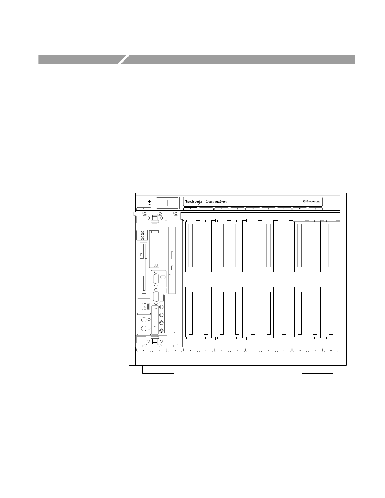
Figure 2–1 shows the front view of the benchtop chassis with a benchtop
controller installed. Figure 2–3 shows the rear view of the benchtop chassis.
Chassis slots 3 through 11 are labeled on the top and bottom of the chassis.
Slots 0, 1 and 2 are reserved for the three slot-wide controller, all other slots are
available for any other TLA 700 Series module.
Figure 2–1: Front view of the benchtop chassis with a benchtop controller
TLA 720 Benchtop Chassis and TLA 7XM Expansion Chassis Service Manual
2–1
Page 40

Operating Information
Fuse
AC Power
Figure 2–2: Front view of the expansion chassis (with out expansion module)
25-Pin PASSIVE
MONITOR connector
Fan speed switch
Figure 2–3: Rear view of the benchtop chassis
2–2
TLA 720 Benchtop Chassis and TLA 7XM Expansion Chassis Service Manual
Page 41

Operating Information
When you install a module, shutters on the bottom of each slot automatically
open to provide cooling.
On/Standby Switch
AC Power Connector
Chassis Ground Screw
Fan Speed Switch
The On/Standby switch on the top-left corner of the front panel applies DC
voltages to the chassis. The switch is a momentary contact switch. The switch is
lighted when DC voltages are applied to the benchtop chassis. The benchtop
chassis can also be remotely controlled.
You can configure the benchtop chassis to bypass the On/Standby switch. (Refer
to Remote Power Switch Configuration on page 4–18 of the Maintenance
chapter for information on configuring the power switch.) In this configuration,
the On/Standby switch remains lighted while power is applied, but the switch
itself no longer controls the benchtop chassis.
The AC power connector is located on the rear bottom left side of the benchtop
chassis. The AC fuse holder is located just above the power connector.
The chassis ground screw can be used to connect more than one benchtop chassis
to a common ground point.
The fan speed switch controls the speed of the blower. When the switch is set to
the VAR (variable) position, the mainframe automatically controls the speed of
the blower depending on the air temperature and amount of cooling required by
the modules. When the switch is in the FULL position, the blower operates at
full speed.
Enhanced Monitor
TLA 720 Benchtop Chassis and TLA 7XM Expansion Chassis Service Manual
The enhanced monitor, in addition to the DB25-pin connector and the fan switch,
includes an industry standard 9-pin RS-232 serial port, logical address switches, a
jumper for slot-1 or slot-12 MODID selection, an auxiliary power connection, a slot
for adding programming FLASH jumper, and status lights. Refer to Figure 2–4.
2–3
Page 42

Operating Information
RS-232C connector
MONITOR BACKUP
POWER SUPPLY
LOGICAL ADDRESS switches
READY light
ACCESSED light
MODID Jumper Selection
Figure 2–4: Rear view of the enhanced monitor
The logical address switches select the logical addresses for the enhanced
monitor. The top switch sets the most-significant digit, the bottom switch sets
the least-significant digit.
The green READY indicator lights after the power-on diagnostics are complete
and there are no failures. During normal operation, the light flashes if there is a
pending error message. Once all error messages have been retrieved, the READY
indicator stops flashing and remains on.
The amber ACCESSED indicator lights when the MODID line is accessed by
the slot 0 device. Refer to Enhanced Monitor Board Jumpers on page 4–23 for
information on the jumper MODID jumper positions.
An auxiliary power connector (MONITOR BACKUP POWER SUPPLY) allows
you to apply +5 V to the enhanced monitor board to provide RS-232 communication with the enhanced monitor while the mainframe is not powered on. The
jumper located just above the power connector determines whether you source
the +5 V standby voltage from the monitor backup power supply connector or
from the 25-pin connector.
For additional information on the enhanced monitor board jumpers, refer to the
Enhanced Monitor Board Jumpers section on page 4–23.
2–4
TLA 720 Benchtop Chassis and TLA 7XM Expansion Chassis Service Manual
Page 43
Selecting the Correct Power Cord and Fuse
The benchtop chassis comes standard with two power cords and three fuses.
Before installing the chassis you must determine the correct fuse and power cord
for your application. Use the following information to determine the appropriate
power cord and line fuse. This information is important to avoid overloading the
power distribution system and to comply with the National Electrical Code.
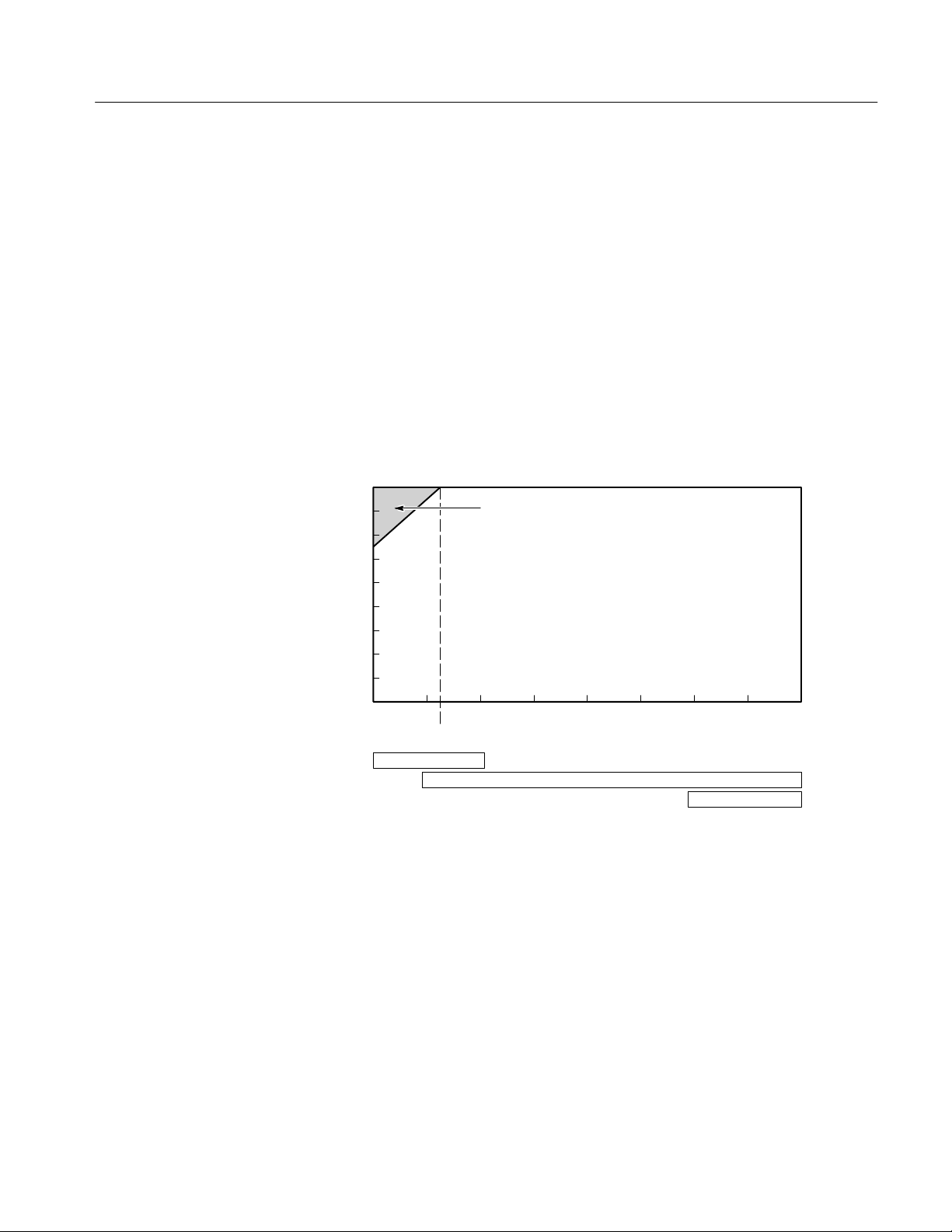
For card cage loads in the nonshaded region of Figure 2–5, use the power cord
with the 15 A plug (Tektronix part number 161-0213-XX) or the power cord
with the 20 A plug (Tektronix part number 161-0218-XX). For high card cage
loads combined with low input line voltages (shaded region), use only the power
cord with the 20 A plug.
Select the proper fuse based on the ranges shown in Figure 2–5.
Operating Information
Power Cord with 20A plug (NEMA 5–20P) ONLY!
Power Cord with 15A plug (NEMA 5–15P)
Power Cord with 20A plug (NEMA 5–20P)
130 150 170 190 210 230 250
Input Line Voltage (Volts AC)
Card Cage Power Consumption (Watts)
800
700
600
500
400
300
200
100
0
90 110
20AT Fuse
115
15AF Fuse
Figure 2–5: Power cord identification chart
6.3AF Fuse
TLA 720 Benchtop Chassis and TLA 7XM Expansion Chassis Service Manual
2–5
Page 44

Operating Information
2–6
TLA 720 Benchtop Chassis and TLA 7XM Expansion Chassis Service Manual
Page 45

Reference
This chapter provides reference information on the mainframe and its connectors.
A description of the command set and information related to the Enhanced
Monitor makes up the remainder of this chapter.
Passive Monitor Connector
The 25-pin Sub-D connector lets you monitor the power supply voltages, fan
speed, and the maximum slot temperature rise within the mainframe.
The connector also provides remote on and off capability and access to the
SYSRESET* and ACFAIL* signals.
Figure 2–6 shows the location of the Passive Monitor Connector. Table 2–1 lists
the pin out of the Passive Monitor Connector and its function.
TLA 720 Benchtop Chassis and TLA 7XM Expansion Chassis Service Manual
2–7
Page 46

Reference
Pin 1
Pin 25
Figure 2–6: Passive monitor connector
2–8
TLA 720 Benchtop Chassis and TLA 7XM Expansion Chassis Service Manual
Page 47

Reference
T able 2–1: Passive monitor connector pinouts
Pin Function Description
1 +5 VM +5 V for voltage monitoring
To monitor, only use a probe with greater than 1 MW impedance.
2 –12 VM –12 V for voltage monitoring
To monitor, only use a probe with greater than 1 MW impedance.
3 –24 VM –24 V for voltage monitoring
To monitor, only use a probe with greater than 1 MW impedance.
4 –2 VM –2 V for voltage monitoring
To monitor, only use a probe with greater than 1 MW impedance.
5 ON/ST Remote On/Standby Power Switch.
6 +5 VC +5 V output for charging batteries, running external TTL circuitry,
1 A maximum
7 +12 VC +12 V output for charging batteries, running external TTL circuitry,
1 A maximum
1
8 +5 VB Input for +5 V standby voltage (for example, from an external
battery). Maximum of 1 A total (pins 8 and 21 combined)
9 GND Logic Ground
10 SYSRESET* Backplane SYSRESET* signal (input or output). If you use this pin,
do not violate VXIbus electrical specifications (keep the extender
cable as short as possible).
11 ∆T An analog output signal proportional to the maximum temperature
rise of the 13 modules (100 mV/°C) 0V=0°C
12 TACH1 A square wave output signal whose period is proporitinal to the
speed of fan number 1
13 TACH2 A square wave output signal whose period is proporitinal to the
speed of fan number 2 when a second fan is used. In the current
mainframe only a single fan is used.
14 +12 VM +12 V for voltage monitoring
To monitor, only use a probe with greater than 1 MW impedance.
15 +24 VM +24 V for voltage monitoring
To monitor, only use a probe with greater than 1 MW impedance.
16 –5.2 VM –5.2 V for voltage monitoring
To monitor, only use a probe with greater than 1 MW impedance.
17 GND Logic Ground
18 GND Logic Ground
2
19 GND Logic Ground
20 GND Logic Ground
TLA 720 Benchtop Chassis and TLA 7XM Expansion Chassis Service Manual
2–9
Page 48

Reference
T able 2–1: Passive monitor connector pinouts (Cont.)
Pin DescriptionFunction
21 +5 VB Input for +5 V standby voltage (for example, from an external
battery). Maximum of 1 A total (pins 8 and 21 combined)
22 GND Logic Ground
23 ACFAIL* Backplane ACFAIL* signal output. If you use this pin, do not violate
the VXIbus electrical specifications (keep the extender cable as
short as possible).
Refer to VMEbus Specification Manual for details on using the
ACFAIL* and SYSRESET* signals.
24 GND Logic Ground
25 RSV Request Service signal
1
By momentarily grounding this line, the mainframe will toggle from on to off (or vice
3
versa). The state changes on the falling edge of the signal. Hold the signal low for at
least 500 ms before releasing. Attach only a momentary switch or an open collector
device to drive this line. The line is pulled up to 1 V internally.
2
If you use pins 8 and 21 (+5 VB) to supply +5 V Standby to the backplane, make sure
that the rear panel jumper is in the correct position (refer to Enhanced Monitor Board
Jumpers on page 4–23).
3
The RSV signal is equivalent to the IEEE 488.1 SRQ signal. The signal is asserted (0)
when an enable event is generated; the signal is unasserted(1) when the event is
cleared by reading the event register. This line is an open collector output. The
signal can be stand-alone or multiple mainframes can be tied together. If you tie
multiple mainframes together , each mainframe must be polled to determine the
source of the service request.
2
2–10
TLA 720 Benchtop Chassis and TLA 7XM Expansion Chassis Service Manual
Page 49

Enhanced Monitor RS-232 Connector
The Enhanced Monitor includes a 9-pin RS-232 connector that allows connection to a RS-232 host. Figure 2–7 shows the pinouts of the 9-pin RS-232
connector; Table 2–2 describes the pin assignments.
Reference
Pin 1
Pin 9
Figure 2–7: RS-232 connector pinout
TLA 720 Benchtop Chassis and TLA 7XM Expansion Chassis Service Manual
2–11
Page 50

Reference
T able 2–2: RS-232 pin connector
Pin Description
Shield Protective Ground
1 No Connection
2 Receive Data (RxD)
3 Transmit Data (TxD)
4 Data Terminal Ready (DTR)
5 Signal Ground (GND)
6 No Connection
7 Request to Send (RTS)
8 Clear to Send (CTS)
9 No Connection
Backplane Connectors
Table 2–3 shows the P1 connector pinouts for all slots in themainframe.
Table 2–4 shows the P2 connector pinouts for slots 1 to 12 and Table 2–5 shows
the pinouts for the Slot 0 P2 connector.
2–12
TLA 720 Benchtop Chassis and TLA 7XM Expansion Chassis Service Manual
Page 51

T able 2–3: P1 connector pinouts
Pin Row A Row B Row C
1 D00 BBSY* D08
2 D01 BCLR* D09
3 D02 ACFAIL* D10
4 D03 BG0IN* D11
5 D04 BG0OUT* D12
6 D05 BG1IN* D13
7 D06 BG1OUT* D14
8 D07 BG2IN* D15
9 GND BG2OUT* GND
10 SYSCLK BG3IN* SYSFAIL*
11 GND BG3OUT* BERR*
12 DS1* BR0* SYSRESET*
Reference
13 DS0* BR1* LWORD*
14 WRITE* BR2* AM5
15 GND BR3* A23
16 DTACK* AM0 A22
17 GND AM1 A21
18 AS* AM2 A20
19 GND AM3 A19
20 IACK* GND A18
21 IACKIN* SERCLK A17
22 IACKOUT* SERDAT* A16
23 AM4 GND A15
24 A07 IRQ7* A14
25 A06 IRQ6* A13
26 A05 IRQ5* A12
27 A04 IRQ4* A11
28 A03 IRQ3* A10
29 A02 IRQ2* A09
30 A01 IRQ1* A08
31 –12 V +5 V STDBY +12 V
32 +5 V +5 V +5 V
TLA 720 Benchtop Chassis and TLA 7XM Expansion Chassis Service Manual
2–13
Page 52

Reference
T able 2–4: P2 connector pinouts for slots 1 – 12
Pin Row A Row B Row C
1 ECLTRG0 +5 V CLK10+
2 –2 V GND CLK10–
3 ECLTRG1 RSV1 GND
4 GND A24 –5.2 V
5 LBUSA00 A25 LBUSC00
6 LBUSA01 A26 LBUSC01
7 –5.2 V A27 GND
8 LBUSA02 A28 LBUSC02
9 LBUSA03 A29 LBUSC03
10 GND A30 GND
11 LBUSA04 A31 LBUSC04
12 LBUSA05 GND LBUSC05
13 –5.2 V +5 V –2 V
14 LBUSA06 D16 LBUSC06
15 LBUSA07 D17 LBUSC07
16 GND D18 GND
17 LBUSA08 D19 LBUSC08
18 LBUSA09 D20 LBUSC09
19 –5.2 V D21 –5.2 V
20 LBUSA10 D22 LBUSC10
21 LBUSA11 D23 LBUSC11
22 GND GND GND
23 TTLTRG0* D24 TTLTRG1*
24 TTLTRG2* D25 TTLTRG3*
25 +5 V D26 GND
26 TTLTRG4* D27 TTLTRG5*
27 TTLTRG6* D28 TTLTRG7*
28 GND D29 GND
29 RSV2 D30 RSV3
2–14
30 MODID D31 GND
31 GND GND +24 V
32 SUMBUS +5 V –24 V
TLA 720 Benchtop Chassis and TLA 7XM Expansion Chassis Service Manual
Page 53

T able 2–5: P2 connector pinouts for slot 0
Pin Row A Row B Row C
1 ECLTRG0 +5 V CLK10+
2 –2 V GND CLK10–
3 ECLTRG1 RSV1 GND
4 GND A24 –5.2 V
5 MODID12 A25 LBUSC00
6 MODID11 A26 LBUSC01
7 –5.2 V A27 GND
8 MODID10 A28 LBUSC02
9 MODID09 A29 LBUSC03
10 GND A30 GND
11 MODID08 A31 LBUSC04
12 MODID07 GND LBUSC05
Reference
13 –5.2 V +5 V –2 V
14 MODID06 D16 LBUSC06
15 MODID05 D17 LBUSC07
16 GND D18 GND
17 MODID04 D19 LBUSC08
18 MODID03 D20 LBUSC09
19 –5.2 V D21 –5.2 V
20 MODID02 D22 LBUSC10
21 MODID01 D23 LBUSC11
22 GND GND GND
23 TTLTRG0* D24 TTLTRG1*
24 TTLTRG2* D25 TTLTRG3*
25 +5 V D26 GND
26 TTLTRG4* D27 TTLTRG5*
27 TTLTRG6* D28 TTLTRG7*
28 GND D29 GND
29 RSV2 D30 RSV3
30 MODID00 D31 GND
31 GND GND +24 V
32 SUMBUS +5 V –24 V
TLA 720 Benchtop Chassis and TLA 7XM Expansion Chassis Service Manual
2–15
Page 54

Reference
Enhanced Monitor
The Enhanced Monitor provides the mainframe with the following additional
capabilities via the RS-232 interface:
H Power supply voltage readouts
H Power supply current readouts
H Power supply wattage readout
H Ambient (input) air temperature readout
H Exhaust temperature readout for each slot
H Fan speed readout
H User-selectable maximum temperature rise
Use defined messages with the DISPlay:TEXT command.
T able 2–6: Messages
Category Message
Power Supply Voltage Messages FAIL:+24V@XX.XX
FAIL:+12V@XX.XX
FAIL:+5V@X.XX
FAIL:+5V STBY@XX.XX
FAIL:+5V EXT@XX.XX
FAIL:–2V@X.XX
FAIL:–5.2V@X.XX
FAIL:–12V@XX.XX
FAIL:–24V@XX.XX
Power Supply Current Average
Messages
FAIL:+24I@XX.XXA
FAIL:+12I@XX.XXA
FAIL:+5I@XX.XXA
FAIL:–2I@XX.XXA
FAIL:–5.2I@XX.XXA
FAIL:–12I@XX.XXA
2–16
FAIL:–24I@XX.XXA
Power Supply message FAIL: Total W@XX.XW
TLA 720 Benchtop Chassis and TLA 7XM Expansion Chassis Service Manual
Page 55

T able 2–6: Messages (Cont.)
Category Message
Slot Temperature messages FAIL:S0 ∆Τ@XX°C
FAIL:S1 ∆Τ@XX°C
FAIL:S2 ∆Τ@XX°C
FAIL:S3 ∆Τ@XX°C
FAIL:S4 ∆Τ@XX°C
FAIL:S5 ∆Τ@XX°C
FAIL:S6 ∆Τ@XX°C
FAIL:S7 ∆Τ@XX°C
FAIL:S8 ∆Τ@XX°C
FAIL:S9 ∆Τ@XX°C
FAIL:S10 ∆Τ@XX°C
FAIL:S11 ∆Τ@XX°C
Reference
FAIL:S12 ∆Τ@XX°C
FAIL:Ambient Τ@XX°C
FAIL:Fan1 XXXXRPM
FAIL:Fan2 XXXXRPM (VX1410A only)
Power Supply Voltage Messages +24 Volts:XX.XXV
+12 Volts:XX.XXV
+5 Volts:X.XXV
+5V Stby:X.XXV
+5V External:X.XXV
–2 Volts:X.XXV
–5.2 Volts:X.XXV
–12 Volts:XX.XXV
–24 Volts:XX.XXV
Power Supply Current Amperage
Messages
+24V Amps:XX.XXA
+12V Amps:XX.XXA
+5V Amps:XX.XXA
–2V Amps:XX.XXA
–5.2V Amps:XX.XXA
–12V Amps:XX.XXA
–24V Amps:XX.XXA
TLA 720 Benchtop Chassis and TLA 7XM Expansion Chassis Service Manual
2–17
Page 56

Reference
T able 2–6: Messages (Cont.)
Category Message
Power Supply Power Messages Total Power:XXX.XW
T emperature Status Messages Ambient T:XX°C
∆Τ S0,S1:XX,XX°C
∆Τ S2,S3:XX,XX°C
∆Τ S4,S5:XX,XX°C
∆Τ S6,S7:XX,XX°C
∆Τ S8,S9:XX,XX°C
∆Τ S10,S11:XX,XX °C
∆Τ S12:XX°C
Fan Status Messages Fan 1 RPM: XXXX
Fan 2 RPM: XXXX (VX1410A only)
Miscellaneous Messages Time On:HHHHHH:MM
Hr of Oper:HHHHHH
Date and Time Message Year–Mon–XX XX:XX
SYSTEM OFF
SYSTEM OK
1
After power on a prompt will appear in the display. Press the PREV and NEXT
buttons to set the date and time. Pressing the PREV or NEXT will cycle through the
values, while pressing both buttons simultaneously moves the cursor to the next
field.
1
2–18
TLA 720 Benchtop Chassis and TLA 7XM Expansion Chassis Service Manual
Page 57

Syntax
SCPI
This section provides an overview of the commands for the mainframe and
includes the following topics:
H A brief introduction to SCPI
H A description of the command syntax
H Instructions on how to enter commands
The commands for the mainframe are compatible with IEEE-488.1, IEEE-488.2,
and SCPI-1995.0 standards.
SCPI (Standard Commands for Programmable Instruments) is a standard created
by an international consortium of the major manufacturers of test and measurement equipment. SCPI uses IEEE-488.2 syntax to provide common commands
for the same functions of various programmable instruments.
The standard simplifies the task of programming a group of instruments that use
SCPI. Instead of having to learn different commands for every instrument, the
programmer may use the same commands for the same functions of each
instrument.
Command Syntax
The controller sends instructions to the instrument in the form of commands or
queries.
H Commands modify control settings or tell the instrument to perform a
specific action.
H Queries cause the instrument to send data or status information back to the
controller.
A question mark at the end of a command header identifies it as a query.
Any instruction that you send to an instrument that complies with SCPI must
have at least three basic elements:
H Command header
H Parameter (if required)
H Message terminator or separator
TLA 720 Benchtop Chassis and TLA 7XM Expansion Chassis Service Manual
2–19
Page 58
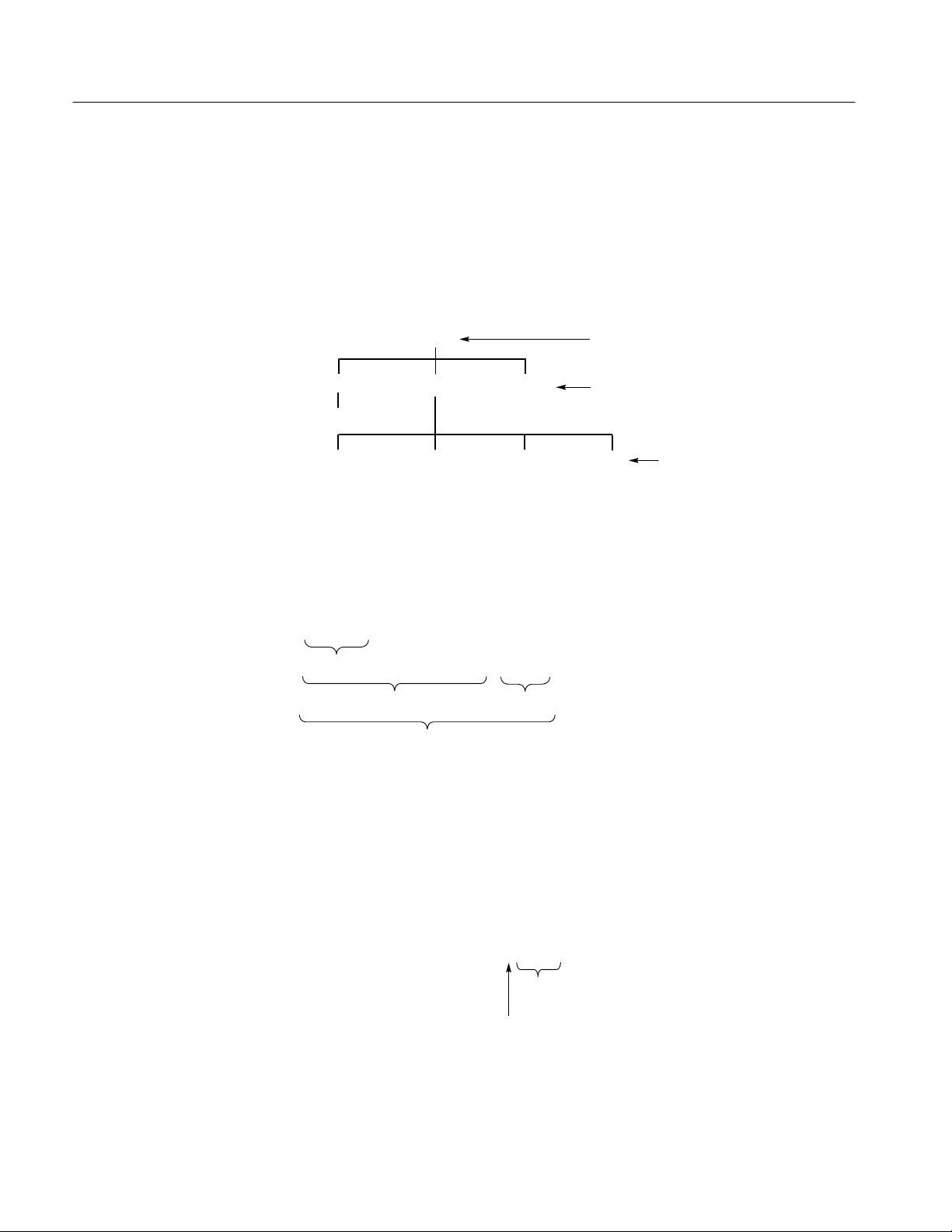
Syntax
Command Headers
The command header has a hierarchical structure that may be represented by a
command tree. An easy-to-remember word called a mnemonic designates each
level of the hierarchy. A colon separates the levels.
The top level of the tree is the root level. A root node is a mnemonic at the root
level. A root node and one or more lower-level nodes form a header path to the
last node called the leaf node.
OPERation
...
[EVENt]?
:STATus
QUEStionable
ENABle
...
ENABle?
Root node
Lower-level
nodes
...
Leaf nodes
Figure 2–8: Tree hierarchy
The header path and leaf node together form the command header. Figure 2–9
shows the command header for the leaf node indicated in Figure.
Parameter
:STATus:QUEStionable:ENABle
Root Node
Header Path
Command Header
Figure 2–9: Command header
You must include values for commands that have parameters. In this manual, the
< > symbols enclose the parameter type when stating the syntax of the command. For example, the syntax of the command in Figure 2–10 includes the
<NRf> parameter type.
:STATus:OPERation:ENABle <NRf>
Figure 2–10: Command header with parameter
Leaf Node
Parameter
Type
Space
2–20
TLA 720 Benchtop Chassis and TLA 7XM Expansion Chassis Service Manual
Page 59

Syntax
NOTE. Do not include the <, >, {,}, or | symbols when entering the actual value for
a parameter.
Separate multiple parameters after a command header with a comma. For
example:
STATus:QUEStionable:TEMPerature:LIMit DELTa1,30
Table 2–7 defines the command and response parameter types for the mainframe.
Table 2–7: Parameter types for syntax descriptions
Parameter type
Boolean Boolean number or value (command parame-
Block A specified length of block-formatted data
Nondecimal numeric Integers in hexadecimal (#H), octal (#Q), or
NR1 Integers (response parameter) 0, 1, 15
NR2 Decimal numbers (response parameter) 1.2, 3.141516, 6.5
NRf Integer, decimal, or floating point number as
discrete A list of specific values (command or response
String Alphanumeric characters within quotation
Description Example
ON or 1
ter, response returns a 1 or 0)
(command parameter)
binary (#B) format (command parameter).
well as MAX and MIN for setting the largest or
smallest value the instrument allows.
(command parameter)
parameter)
marks (command or response parameter)
OFF or 0
#212xxxxxxxxxxxx
where 2 indicates that
the following 2 digits
(12) specify the length
of the following block
data (xxx...)
#H00FF, #B010101,
#Q0753
1, 3E+1, MAX, 2.6
P24, P5EXT, N2, ...
“No error”
Parameter values that appear in this manual are often enclosed in curly braces
({}) separated by a vertical line. This vertical line means the same thing as the
word “or.” For example, values for the parameter <Boolean> are
{0|1|OFF|ON}
This is the same thing as saying “0 or 1 or OFF or ON.” Any single value is a
valid parameter.
TLA 720 Benchtop Chassis and TLA 7XM Expansion Chassis Service Manual
2–21
Page 60

Syntax
Message Terminator and
Message Separator
In accordance with IEEE 488.2 specification, the mainframe accepts any of the
following message terminators:
H LF^END Linefeed code (hexadecimal 0A) with the END bit in the
Byte Available command asserted.
H LF Linefeed code
H <dab>^END Last data byte with the END bit in the Byte Available
command asserted.
A semicolon separates one command from another when the commands appear
on the same line. See Entering Commands.
2–22
TLA 720 Benchtop Chassis and TLA 7XM Expansion Chassis Service Manual
Page 61

Entering Commands
Syntax
The standards that govern the command set for the mainframe allows for a
certain amount of flexibility when you enter commands.
For example, you can abbreviate many commands or combine commands into
one message that you send to the mainframe. This flexibility, called “friendly
listening,” saves programming time and makes the command set easier to
remember and use.
Command Characters
Abbreviating Commands
The mainframe is not sensitive to the case of command characters. You can enter
commands in either upper or lower case.
You can precede any command with white space characters. White space
characters include a space or any combination of the ASCII control characters
hexadecimal 00 through 1F except for the character 0A (new line). You must,
however, use at least one space between the parameter and the command header.
Most commands have a long form and a short form. The listing for each
command in this section shows the abbreviations in upper case. For example,
you can enter the query SYSTem:ERRor? simply as SYST:ERR? (or syst:err?).
The brackets around a mnemonic indicate that the mainframe assumes this level
of the command header by default. It is not necessary, therefore, for this
mnemonic to appear as part of the header when you send the command. For
example, you can abbreviate the command
STATus:OPERational[:EVENt]?
to
STAT:OPER?
Because the mainframe assumes that a command at the beginning of a program
message starts from the root, you have the option of beginning the initial
command header with a colon (:).
Combining Commands
TLA 720 Benchtop Chassis and TLA 7XM Expansion Chassis Service Manual
You can combine (concatenate) commands and queries using a semicolon (;).
The mainframe executes concatenated commands in the order it receives them.
When you concatenate queries, the mainframe combines the responses into a
single response message.
For example: Querying both the standard event status register and the error/event
queue in the same program message.
STATus:OPERation?;:SYSTem:ERRor?
2–23
Page 62

Syntax
returns the response message
0;0,"No errors"
If the command that follows the semicolon has a different header path from the
root level, you must use a colon to force a return to the root level:
SYSTem:VERSion?;:TEST:RESult?
If the command that follows the semicolon has the same header path, you may
omit the colon and the path and state only the new leaf node. This makes it
possible, for example, to shorten the concatenated query
SYSTem:TIME:LMAintenance?;:SYSTem:TIME:ON?
into
SYSTem:TIME:LMAintenance?;ON?
The 488.2 common commands that begin with an asterisk (*) may be used
anywhere in a command sequence with no effect on the command header path.
SYSTem:VERSion?;*ESR?
returns
1995.0;16
You can combine commands and queries into the same message. Note, for
example, the following combination which sets the temperature limit and queries
to verify the setting
status:questionable:temperature:limit AMBient,25;limit?
AMBient
2–24
TLA 720 Benchtop Chassis and TLA 7XM Expansion Chassis Service Manual
Page 63

Command Groups
This section lists mainframe commands by functional groups. A question symbol
surrounded by brackets [?] identifies commands that also have a query form.
Status Commands
Commands in the STATus subsystem, along with several IEEE 488.2 Common
Commands, control the status and event reporting system.
T able 2–8: Status commands
Header Description
:BLOWer? Returns the contents of the Blower Event register.
:CONDition? Returns the contents of the Blower Condition register.
:CURRent? Returns the contents of the Current Event register.
:CMAXimum? Returns the maximum current level since power on.
:CONDition? Returns the contents of the Current Condition register.
:LEVel? Returns current level.
:LIMit[?] Sets or queries the maximum current usage allowed
before generating an alarm.
:MAXimum? Returns the maximum current level since the last factory
maintenance.
:ENABle[?] Sets or queries the contents of the Blower Enable
register.
:SPEed? Returns the fan speed in revolutions per minute.
:CONDition? Returns the contents of the Questionable Condition
register.
:ENABle[?] Sets or queries the contents of the Questionable Status
Enable register.
:CMAXimum? Returns the maximum power used since power up.
:CONDition? Returns the contents of the power condition register.
:ENABle[?] Sets or queries the contents of the power enable
register.
:LEVel? Returns the wattage used by the mainframe.
:LIMit[?] Set or query the maximum amount of power allowed
before generating an alarm.
TLA 720 Benchtop Chassis and TLA 7XM Expansion Chassis Service Manual
2–25
Page 64

Command Groups
T able 2–8: Status commands (Cont.)
Header Description
:MAXimum? Returns the maximum power high mark used since the
last factory maintenance.
:TEMPerature? Returns the contents of the Temperature Event register
as a decimal number.
:CMAXimum? Returns the maximum measurable temperatures in the
mainframe since power on.
:CONDition? Returns the contents of the Temperature Condition
register.
:ENABle[?] Sets or queries the contents of the Temperature Enable
register.
:LEVel? Returns the current temperatures in the mainframe.
:LIMit[?] Sets or queries the maximum ambient and delta
temperatures in each slot of the mainframe.
:MAXimum? Returns the maximum measurable temperatures in the
mainframe since the last factory maintenance.
:VOLTage? Returns the contents of the Voltage Event register as a
decimal number.
:CONDition? Returns the contents of the Voltage Condition register.
:ENABle[?] Sets or queries the contents of the Voltage Enable
register.
:LEVel? Returns the current power supply output voltages.
:PTR[?] Sets or queries the power supply positive transition filter.
:QUEue? Returns the next message in the error queue.
[:NEXT]? Returns the next event code and message from the
Error/Event queue.
:ALL? Returns a comma-separated list of all unread events
from the Error/Event queue.
:CODE? Returns the next event code from the Error/Event queue.
:ALL? Returns a comma-separated list of all unread event
codes from the Error/Event queue.
:COUNt? Returns the number of unread events from the
Error/Event queue.
:ENABle[?] Sets or queries enable events to be placed in the
Error/Event queue.
:ALL Presets the Error/Event queue enable to –1999:1000.
2–26
:SCONdition? Returns a summary condition of all monitors.
:S2CONdition? Returns the overflow summary information of the
condition registers.
TLA 720 Benchtop Chassis and TLA 7XM Expansion Chassis Service Manual
Page 65

System Commands
Command Groups
T able 2–8: Status commands (Cont.)
Header Description
:SEVent? Returns summary information of all events in the
mainframe.
:S2EVent? Returns the overflow summary information for events in
the mainframe.
Commands in the SYSTem subsystem program utility functions provide version
information about the mainframe.
T able 2–9: System commands
Header Description
SYSTem
:COMMunicate
:SERial
:BAUD[?] Sets or queries the baud rate of the RS-232 port.
:BITS[?] Sets or queries the number of bits per character in the
RS-232 port.
:CONTrol
:RTS[?] Sets or queries the operation of the RTS and CTS lines.
:ECHO[?] Sets or queries whether incoming characters are echoed
back to the RS-232 port.
:ERESponse[?] Sets or queries whether error messages are automatically
returned to the RS-232 port.
:LBUFfer[?] Sets or queries the state of the character buffer .
:PACE[?] Sets or queries whether software flow control (XON/XOFF)
is enabled.
:PARity[?] Sets or queries the type of parity for the RS-232 port.
:PRESet
[:ALL] Configures RS-232 port parameters to default values.
:RAW Configures the RS-232 port parameters for use with a
computer.
:TERMinal Configures the RS-232 port parameters for use with a
terminal.
TLA 720 Benchtop Chassis and TLA 7XM Expansion Chassis Service Manual
2–27
Page 66

Command Groups
T able 2–9: System commands (Cont.)
Header Description
:SBITs[?] Sets or queries the number of stop bits sent with each
character.
:DATE[?] Sets or queries the calendar date.
:LMAintenance? Returns the last factory maintenance date.
:ERRor? Returns the next entry from the Error/Event queue.
:ALL? Returns a comma separated list of all events stored in the
Error/Event queue.
:CODE? Returns the next event code stored in the Error/Event
queue.
:ALL? Returns a comma separated list of all event codes stored in
Error/Event queue.
:COUNt? Returns the number of unread events in the Error/Event
queue.
:ENABle[?] Sets or queries enable events to be placed in the
Error/Event queue.
:ALL? Presets the Error/Event queue enable to –1999:1000.
:FACTory Sets the mainframe settings to the factory default values.
:HELP
:SYNTax? Returns the syntax of the specified command.
:IEMessage Sends interface event messages between the VXI interface
and the RS-232 port.
:MODel? Returns the model number of the mainframe.
:NVRecall Recalls device settings from nonvolatile RAM.
:NVSave Saves device settings to nonvolatile RAM.
:OPTions Returns the options installed in the mainframe.
:PASSword
:CDISable
:CENable
:STATe?
1
1
1
Disables the CALibrate command.
Enables the CALibrate command.
Queries if password-protected commands are enabled.
:POWer[?] Powers the mainframe on or off. The query returns whether
the power is on or off.
2–28
:CYCLe? Queries the number of times the mainframe power has been
cycled.
:SOURce? Queries the power source of the enhanced monitor.
:SYSReset[?] Sets or queries whether the VXI SYSRESET signal can
reset the enhanced monitor.
TLA 720 Benchtop Chassis and TLA 7XM Expansion Chassis Service Manual
Page 67

Test Commands
Command Groups
T able 2–9: System commands (Cont.)
Header Description
:IMMediate Initiates a VXI SYSRESET signal.
:TIME[?] Sets or queries the time.
:LMAintenance? Returns the number of hours the mainframe has been
operating since the last factory maintenance.
:ON? Returns the number of hours the mainframe has been
operating since power on.
:VERSion? Returns the SCPI version supported by the mainframe.
1
These commands are intend to be used only by qualified service personnel while
servicing the instrument.
Commands in the TEST subsystem execute the internal self-tests of the
mainframe
T able 2–10: Test commands
Header Description
TEST
[:ALL][?] Executes all internal self tests once. The query returns the
test results.
:NUMBer[?] Executes a test. The query returns the test result.
:RESults? Returns the failure code for the last self-test command that
was executed.
:VERBose? Returns a failure code as a string describing the last
executed self-test command and the test results.
TLA 720 Benchtop Chassis and TLA 7XM Expansion Chassis Service Manual
2–29
Page 68

Command Groups
STATus:QUEStionable:BLOWer?
Queries the contents of the Blower Event register. A value of one in a bit
indicates the corresponding condition bit changed from false to true and that
there may be a problem with one of the fans. Unused bits always return a value
of zero. The register is cleared by the *CLS command.
There is no command associated with this query.
Syntax
Parameters
STATus:QUEStionable:BLOWer[:EVENt]?
Parameter Query response
Not applicable <NR1>
Blower status word bits Definition
D0 Blower 1
D1 Blower 2
D2 Not Used
D3 Not Used
D4 Not Used
D5 Not Used
D6 Not Used
D7 Not Used
D8 Not Used
D9 Not Used
2–30
Reset Value
Errors and Events
D10 Not Used
D11 Not Used
D12 Not Used
D13 Not Used
D14 Not Used
D15 Not Used
Not Applicable
None
TLA 720 Benchtop Chassis and TLA 7XM Expansion Chassis Service Manual
Page 69

Command Groups
Dependencies
Examples
Related Commands
Reading the register clears it.
Query: STAT:QUES:BLOW?
Response: 0
STATus:QUEStionable:BLOWer:CONDition?
STATus:QUEStionable:BLOWer:ENABle
TLA 720 Benchtop Chassis and TLA 7XM Expansion Chassis Service Manual
2–31
Page 70

Command Groups
STATus:QUEStionable:BLOWer:CONDition?
Returns the contents of the Blower Condition register. A value of one in a bit
indicates possible problems with one of the fans. Unused always return a value
of zero. Definition of the bits in this register can be found under the
STATus:QUEStionable:BLOWer command on page 2–30.
Reading this register does not clear it.
There is no command associated with this query.
Syntax
Parameters
Reset Value
Errors and Events
Dependencies
Examples
Related Commands
STATus:QUEStionable:BLOWer:CONDition?
Parameter Query response
Not applicable <NR1>
Not Applicable
None
None
Query: STAT:QUES:BLOW:COND?
Response: 0
STATus:QUEStionable:BLOWer?
STATus:QUEStionable:BLOWer:ENABle
2–32
TLA 720 Benchtop Chassis and TLA 7XM Expansion Chassis Service Manual
Page 71

STATus:QUEStionable:BLOWer:ENABle?
Sets or queries the contents of the Blower Enable register. Setting unused enable
bits does not generate an error; the bits are ignored. Enabling bits in the register
allows information from the Blower Event register to be passed on to the
Questionable Event register.
If the power-on status clear flag is FALSE (see *PSC command on page 2–79) at
power on, the register value will be restored from nonvolatile RAM; otherwise
the register value at power on is set to #H7FFF. Executing the STATus:PRESet
command sets the register value to #H7FFF.
Command Groups
Syntax
Parameters
Reset Value
Errors and Events
Dependencies
Examples
STATus:QUEStionable:BLOWer:ENABle <Mask>
STATus:QUEStionable:BLOWer:ENABle?
<Mask> Query response
{<NRf> | <Nondecimal Numeric>}
0 ≤ N ≤ #HFFFF
Not Applicable
–222, “Data Out of Range”
You attempted to set the enable register to an illegal value.
None
Command: STAT:QUES:BLOW:ENAB #H0000
Query: STAT:QUES:BLOW:ENAB?
<NR1>
Response: 0
Related Commands
TLA 720 Benchtop Chassis and TLA 7XM Expansion Chassis Service Manual
STATus:QUEStionable:BLOWer?
STATus:QUEStionable:BLOWer:CONDition?
STATus:PRESet
2–33
Page 72

Command Groups
STATus:QUEStionable:BLOWer:SPEed?
Queries the current fan (blower) rotational speed in revolutions per minute (RPM). Normal values are 1200 to 3350 for the VX1410A and 650 to 2250
for the VX1420A.
There is no command associated with this query.
Syntax
Parameters
Reset Value
Errors and Events
Dependencies
Examples
Related Commands
STATus:QUEStionable:BLOWer:SPEed? <Blower>
<Blower> Query response
{BLOWer1 | BLOWer2} <NR1>
Not Applicable
–224, “Illegal Parameter Value”
You attempted to use an invalid parameter value.
None
Query: STAT:QUES:BLOW:SPE? BLOW1
Response: 1200
STATus:QUEStionable:BLOWer?
STATus:QUEStionable:BLOWer:CONDition?
STATus:QUEStionable:BLOWer:ENABle
2–34
TLA 720 Benchtop Chassis and TLA 7XM Expansion Chassis Service Manual
Page 73

STATus:QUEStionable:CONDition?
Queries the contents of the Questionable Condition register. Unused bits always
return a value of zero.
Reading the register does not clear it.
There is no command associated with this query.
Command Groups
Syntax
Parameters
Reset Value
Errors and Events
Dependencies
Examples
Related Commands
STATus:QUEStionable:CONDition?
Parameter Query response
Not Applicable <NR1>
Not Applicable
None
None
Query: STAT:QUES:COND?
Response: 0
STATus:QUEStionable?
STATus:QUEStionable:ENABle
TLA 720 Benchtop Chassis and TLA 7XM Expansion Chassis Service Manual
2–35
Page 74

Command Groups
STATus:QUEStionable:CURRent?
Queries the contents of the Current Event register. A one in a bit indicates the
corresponding power supply failure event has been asserted. Unused bits always
return a value of zero. The register is also cleared by the *CLS command.
There is no command associated with this query.
Syntax
Parameters
STATus:QUEStionable:CURRent[:EVENt]?
<Event> Query response
Not applicable <NR1>
Current status word bits Definition
D0 +24 V
D1 +12 V
D2 +5 V
D3 Not Used
D4 Not Used
D5 –2 V
D6 –5.2 V
D7 –12 V
D8 –24 V
D9 Not Used
2–36
Reset Value
Errors and Events
Dependencies
D10 Not Used
D11 Not Used
D12 Not Used
D13 Not Used
D14 Not Used
D15 Not Used
Not Applicable
None
Reading the register clears it.
TLA 720 Benchtop Chassis and TLA 7XM Expansion Chassis Service Manual
Page 75

Command Groups
Examples
Related Commands
Query: STAT:QUES:CURR?
Response: 0
STATus:QUEStionable:CURRent:CONDition?
STATus:QUEStionable:CURRent:ENABle
TLA 720 Benchtop Chassis and TLA 7XM Expansion Chassis Service Manual
2–37
Page 76

Command Groups
STATus:QUEStionable:CURRent:CMAXimum?
Queries the current maximum measurable power supply currents within the
mainframe since power on; the returned value is in amperes.
There is no command associated with this query.
Syntax
Parameters
Reset Value
Errors and Events
Dependencies
Examples
Related Commands
STATus:QUEStionable:CURRent:CMAXimum? <power supply>
<Power supply> Query response
{P24 | P12 | P5 | N2 | N5PT2 | N12 | N24} <NR2>
Not Applicable
–224, “Illegal Parameter Value”
You attempted to use an illegal parameter value.
None
Query: STAT:QUES:CURR:CMAX? P12
Response: 5.1
STATus:QUEStionable:CURRent:LEVel?
STATus:QUEStionable:CURRent:MAXimum?
2–38
TLA 720 Benchtop Chassis and TLA 7XM Expansion Chassis Service Manual
Page 77

STATus:QUEStionable:CURRent:CONDition?
Queries the contents of the Current Condition register. A value of one in a bit
indicates the corresponding power supply is currently failing. Unused bits always
return a value of zero. Definition of the bits in this register can be found in
STATus:QUEStionable:CURRent? command.
Reading the register does not clear it.
There is no command associated with this query.
Command Groups
Syntax
Parameters
Reset Value
Errors and Events
Dependencies
Examples
Related Commands
STATus:QUEStionable:CURRent:CONDition?
Parameter Query response
Not Applicable <NR1>
Not Applicable
None
None
Query: STAT:QUES:CURR:COND?
Response:0
STATus:QUEStionable:CURRent?
STATus:QUEStionable:CURRent:ENABle
TLA 720 Benchtop Chassis and TLA 7XM Expansion Chassis Service Manual
2–39
Page 78

Command Groups
STATus:QUEStionable:CURRent:ENABle?
Sets or queries the contents of the Current Enable register. Setting unused enable
bits does not generate an error; the bits are ignored.
If the power-on status clear flag is FALSE (see *PSC command on page 2–79) at
power on, the register value will be restored from nonvolatile RAM; otherwise,
the register value at power on is set to #H7FFF. Executing the STATus:PRESet
command sets the register value to #H7FFF.
Syntax
Parameters
Reset Value
Errors and Events
Dependencies
Examples
STATus:QUEStionable:CURRent:ENABle <Mask>
STATus:QUEStionable:CURRent:ENABle?
<Mask> Query response
<NRf> | <Nondecimal Numeric>
0 ≤ N ≤ #HFFFF
Not Applicable
–222, “Data Out of Range”
You attempted to set the enable register to an illegal value.
None
Command: STAT:QUES:CURR:ENAB #H3FFF
Query: STAT:QUES:CURR:ENAB?
<NR1>
2–40
Related Commands
Response: 16383
STATus:QUEStionable:CURRent?
STATus:QUEStionable:CURRent:CONDition?
STATus:PRESet
TLA 720 Benchtop Chassis and TLA 7XM Expansion Chassis Service Manual
Page 79

STATus:QUEStionable:CURRent:LEVel?
Queries the current power supply output amperage.
There is no command associated with this query.
Command Groups
Syntax
Parameters
Reset Value
STATus:QUEStionable:CURRent:LEVel? <Power Supply>
<Power supply> Query response
{P24 | P12 | P5 | N2 | N5PT2 | N12 | N24} <NR2>
Code Power supply
P24 +24V
P12 +12V
P5 +5V
N2 –2V
N5PT2 –5.2V
N12 –12V
N24 –24V
Not Applicable
Errors and Events
Dependencies
Examples
Related Commands
TLA 720 Benchtop Chassis and TLA 7XM Expansion Chassis Service Manual
–224, “Illegal Parameter Value”
You attempted to use an illegal parameter value.
None
Query: STAT:QUES:CURR:LEV? P5
Response: 5.11
STATus:QUEStionable:CURRent?
STATus:QUEStionable:CURRent:CONDition?
STATus:QUEStionable:CURRent:ENABle
2–41
Page 80

Command Groups
STATus:QUEStionable:CURRent:LIMit?
Sets or queries the maximum allowable current to be drawn from each of the
power supplies.
Syntax
Reset Value
Errors and Events
STATus:QUEStionable:CURRent:LIMit <Location>,<Limit>
STATus:QUEStionable:CURRent:LIMit? <Location>
<Location> Query response (Amperes)
{P24 | P12 | P5 | N2 | N5 | N12 | N24} <NR2>
<Limit>
<NRf>
MIN {all supplies}
MAX {each supply}
P24
P12
P5
N2
N5PT2
N12
N24
0.0
13.0
13.0
95.0
–30.0
–60.0
–13.0
–13.0
Not Applicable
–224, “Illegal Parameter Value”
You attempted to set the location to an illegal value.
2–42
Dependencies
Examples
Related Commands
–222, “Data Out of Range”
You attempted to set the current limit to an illegal value.
None
Query: STAT:QUES:CURR:LIM? P24
Response: 12.0
STATus:QUEStionable:CURRent?
STATus:QUEStionable:CURRent:CONDition?
STATus:QUEStionable:CURRent:ENABle
STATus:QUEStionable:CURRent:LEVel?
TLA 720 Benchtop Chassis and TLA 7XM Expansion Chassis Service Manual
Page 81

STATus:QUEStionable:CURRent:MAXimum?
Queries the current maximum measurable power supply currents within the
mainframe since the last factory maintenance was performed; the returned value is
in amperes.
There is no command associated with this query.
Command Groups
Syntax
Parameters
Reset Value
Errors and Events
Dependencies
Examples
Related Commands
STATus:QUEStionable:CURRent:MAXimum? <power supply>
<Power supply> Query response (Amperes)
{P24 | P12 | P5 | N2 | N5PT2 | N12 | N24} <NR2>
Not Applicable
–224, “Illegal Parameter Value”
You attempted to use an illegal parameter value.
None
Query: STAT:QUES:CURR:MAX? P12
Response: 7.1
STATus:QUEStionable:CURRent:LEVel?
STATus:QUEStionable:CURRent:CMAXimum?
TLA 720 Benchtop Chassis and TLA 7XM Expansion Chassis Service Manual
2–43
Page 82

Command Groups
STATus:QUEStionable:POWer?
Queries the contents of the Power Event register. A one in the corresponding bit
indicates the power supply failure event has been asserted. Unused bits always
return a value of zero. The register is also cleared by the *CLS command.
There is no command associated with this query.
Syntax
Parameters
STATus:QUEStionable:POWer[:EVENt]?
<Event> Query response
Not applicable <NR1>
Current status word bits Definition
D0 Not Used
D1 Not Used
D2 Not Used
D3 Not Used
D4 Not Used
D5 Not Used
D6 Not Used
D7 Not Used
D8 Not Used
D9 Total Power occurred
2–44
Reset Value
Errors and Events
Dependencies
D10 Not Used
D11 Not Used
D12 Not Used
D13 Not Used
D14 Not Used
D15 Not Used
Not Applicable
None
Reading the register clears it.
TLA 720 Benchtop Chassis and TLA 7XM Expansion Chassis Service Manual
Page 83

Command Groups
Examples
Related Commands
Query: STAT:QUES:POW?
Response: 0
STATus:QUEStionable:POWer:CONDition?
STATus:QUEStionable:POWer:ENABle
TLA 720 Benchtop Chassis and TLA 7XM Expansion Chassis Service Manual
2–45
Page 84

Command Groups
STATus:QUEStionable:POWer:CMAXimum?
Queries the current maximum measurable total power supply wattage within the
mainframe since power on; the returned value is in watts.
There is no command associated with this query.
Syntax
Parameters
Reset Value
Errors and Events
Dependencies
Examples
Related Commands
STATus:QUEStionable:POWer:CMAXimum?
<Power supply> Query response
Not Applicable <NR2>
Not Applicable
None
None
Query: STAT:QUES:POW:CMAX?
Response: 824.5
STATus:QUEStionable:POWer:LEVel?
STATus:QUEStionable:POWer:MAXimum?
2–46
TLA 720 Benchtop Chassis and TLA 7XM Expansion Chassis Service Manual
Page 85
STATus:QUEStionable:POWer:CONDition?
Queries the contents of the Power Condition register. A value of one in the 9 bit
indicates the power supply is over limits. Unused bits always return a value of
zero. Definition of the bits in this register can be found in STATus:QUEStionable:POWer? command.
Reading the register does not clear it.
There is no command associated with this query.
Command Groups
Syntax
Parameters
Reset Value
Errors and Events
Dependencies
Examples
Related Commands
STATus:QUEStionable:POWer:CONDition?
Parameter Query response
Not Applicable <NR1>
Not Applicable
None
None
Query: STAT:QUES:POW:COND?
Response:0
STATus:QUEStionable:POWer?
STATus:QUEStionable:POWer:ENABle
TLA 720 Benchtop Chassis and TLA 7XM Expansion Chassis Service Manual
2–47
Page 86

Command Groups
STATus:QUEStionable:POWer:ENABle?
Sets or queries the contents of the Power Enable register. Setting unused enable
bits does not generate an error; the bits are ignored.
If the power-on status clear flag is FALSE (see *PSC command on page 2–79) at
power on, the register value will be restored from nonvolatile RAM; otherwise
the register value at power on is set to #H7FFF. Executing the STATus:PRESet
command sets the register value to #H7FFF.
Syntax
Parameters
Reset Value
Errors and Events
Dependencies
Examples
STATus:QUEStionable:POWer:ENABle <Mask>
STATus:QUEStionable:POWer:ENABle?
<Mask> Query response
<NRf> | <Nondecimal Numeric>
0 ≤ N ≤ #HFFFF
Not Applicable
–222, “Data Out of Range”
You attempted to set the enable register to an illegal value.
None
Command: STAT:QUES:POW:ENAB #H3FFF
Query: STAT:QUES:POW:ENAB?
<NR1>
2–48
Related Commands
Response: 512
STATus:QUEStionable:POWer?
STATus:QUEStionable:POWer:CONDition?
STATus:PRESet
TLA 720 Benchtop Chassis and TLA 7XM Expansion Chassis Service Manual
Page 87

STATus:QUEStionable:POWer:LEVel?
Queries the total power supply output wattage.
There is no command associated with this query.
Command Groups
Syntax
Parameters
Reset Value
Errors and Events
Dependencies
Examples
Related Commands
STATus:QUEStionable:POWer:LEVel?
<Power Supply> Query response
Not Applicable <NR2>
Not Applicable
None
None
Query: STAT:QUES:POW:LEV?
Response: 812.3
STATus:QUEStionable:POWer?
STATus:QUEStionable:POWer:CONDition?
STATus:QUEStionable:POWer:ENABle
TLA 720 Benchtop Chassis and TLA 7XM Expansion Chassis Service Manual
2–49
Page 88

Command Groups
STATus:QUEStionable:POWer:LIMit?
Sets or queries the maximum allowable power to be drawn from the entire power
supply.
Syntax
Reset Value
Errors and Events
Dependencies
Examples
STATus:QUEStionable:POWer:LIMit <Limit>
STATus:QUEStionable:POWer:LIMit?
<Limit> Query response
<NRf>
MIN
MAX
Not Applicable
–222, “Data Out of Range”
You attempted to set the power limit to an illegal value.
None
Query: STAT:QUES:POW:LIM?
Response: 675.0
<NR2>
0.0
VX1410A: 925.0
VX1420A: 1000.0
2–50
Related Commands
STATus:QUEStionable:POWer?
STATus:QUEStionable:POWer:CONDition?
STATus:QUEStionable:POWer:ENABle
STATus:QUEStionable:POWer:LEVel?
TLA 720 Benchtop Chassis and TLA 7XM Expansion Chassis Service Manual
Page 89

STATus:QUEStionable:POWer:MAXimum?
Queries the current maximum measurable total power supply wattage within the
mainframe since the last factory maintenance was performed; the returned value is
in watts.
There is no command associated with this query.
Command Groups
Syntax
Parameters
Reset Value
Errors and Events
Dependencies
Examples
Related Commands
STATus:QUEStionable:POWer:MAXimum?
<Power supply> Query response
Not Applicable <NR2>
Not Applicable
None
None
Query: STAT:QUES:POW:MAX?
Response: 876.3
STATus:QUEStionable:POWer:LEVel?
STATus:QUEStionable:POWer:CMAXimum?
TLA 720 Benchtop Chassis and TLA 7XM Expansion Chassis Service Manual
2–51
Page 90

Command Groups
STATus:QUEStionable:TEMPerature?
Returns the contents of the Temperature Event register. A value of one in a bit
indicates the corresponding condition bit has transitioned from false to true.
Unused bits always return a value of zero. The register is cleared by the *CLS
command.
There is no command associated with this query.
Syntax
Parameters
STATus:QUEStionable:TEMPerature[:EVENt]?
Parameter Query response
Not applicable <NR1>
Blower status word bits Definition
D0 Slot 0 Delta Temperature
D1 Slot 1 Delta Temperature
D2 Slot 2 Delta Temperature
D3 Slot 3 Delta Temperature
D4 Slot 4 Delta Temperature
D5 Slot 5 Delta Temperature
D6 Slot 6 Delta Temperature
D7 Slot 7 Delta Temperature
D8 Slot 8 Delta Temperature
D9 Slot 9 Delta Temperature
2–52
Reset Value
Errors and Events
D10 Slot 10 Delta Temperature
D11 Slot 11 Delta Temperature
D12 Slot 12 Delta Temperature
D13 Ambient Temperature
D14 Not Used
D15 Not Used
Not Applicable
None
TLA 720 Benchtop Chassis and TLA 7XM Expansion Chassis Service Manual
Page 91

Command Groups
Dependencies
Examples
Related Commands
Reading the register clears it.
Query: STAT:QUES:TEMP?
Response: 1
STATus:QUEStionable:TEMPerature:CONDition?
STATus:QUEStionable:TEMPerature:ENABle
TLA 720 Benchtop Chassis and TLA 7XM Expansion Chassis Service Manual
2–53
Page 92

Command Groups
STATus:QUEStionable:TEMPerature:CMAXimum?
Queries the current maximum measurable temperatures in the mainframe since
power on. The returned value is in °C.
There is no command associated with this query.
Syntax
Parameters
Reset Value
Errors and Events
Dependencies
Examples
STATus:QUEStionable:TEMPerature:CMAXimum? <Location>
<Location> Query response
{AMBient | OUT0 . . . OUT12 | DELTa0 . . .
DELTa12}
AMBient – ambient input temperature
OUT0 . . . OUT12 – output temperature of
each slot
DEL Ta0 . . . DELTa12 – output temperature
minus input temperature of each slot
Not Applicable
–224, “Illegal Parameter Value”
You attempted to use an illegal parameter value.
None
Query: STAT:QUES:TEMP:CMAX? DELTA12
<NR1>
2–54
Related Commands
Response: 50
STATus:QUEStionable:TEMPerature:LEVel?
STATus:QUEStionable:TEMPerature:MAXimum?
TLA 720 Benchtop Chassis and TLA 7XM Expansion Chassis Service Manual
Page 93
STATus:QUEStionable:TEMPerature:CONDition?
Queries the contents of the Temperature Condition register. A value of one in a
bit indicates the corresponding temperature condition is outside of the limits.
Unused bits always return a value of zero. Definition of the bits in this register
can be found under the STATus:QUEStionable:TEMPerature? command on
page 2–52.
If the fan speed is already set to the maximum speed and the delta temperature is
above the limit for 30 seconds, a failure will be reported.
Reading the register does not clear it.
There is no command associated with this query.
Command Groups
Syntax
Parameters
Reset Value
Errors and Events
Dependencies
Examples
Related Commands
STATus:QUEStionable:TEMPerature:CONDition?
Parameter Query response
Not Applicable <NR1>
Not Applicable
None
None
Query: STAT:QUES:TEMP:COND?
Response: 0
STATus:QUEStionable:TEMPerature?
STATus:QUEStionable:TEMPerature:ENABle
TLA 720 Benchtop Chassis and TLA 7XM Expansion Chassis Service Manual
2–55
Page 94
Command Groups
STATus:QUEStionable:TEMPerature:ENABle?
Sets or queries the contents of the Temperature Enable register. Setting unused
enable bits does not generate an error; the bits are ignored.
If the power-on status clear flag is FALSE (see *PSC command on page 2–79) at
power on, the register value will be restored from nonvolatile RAM;
otherwise, the register value at power on is set to #H7FFF. Executing the
STATus:PRESet command sets the register value to #H7FFF.
Syntax
Parameters
Reset Value
Errors and Events
Dependencies
Examples
STATus:QUEStionable:TEMPerature:ENABle <Mask>
STATus:QUEStionable:TEMPerature:ENABle?
<Mask> Query response
{<NRf> | <Nondecimal Numeric>}
0 ≤ N ≤ #HFFFF
Not Applicable
–222, “Data Out of Range”
You attempted to set the enable register to an illegal value.
None
Command: STAT:QUES:TEMP:ENAB #H7FFF
Query: STAT:QUES:TEMP:ENAB?
<NR1>
2–56
Related Commands
Response: 32767
STATus:QUEStionable:TEMPerature?
STATus:QUEStionable:TEMPerature:CONDition?
STATus:PRESet
TLA 720 Benchtop Chassis and TLA 7XM Expansion Chassis Service Manual
Page 95
STATus:QUEStionable:TEMPerature:LEVel?
Returns the current temperatures in the mainframe; the returned value is in °C.
There is no command associated with this query.
Command Groups
Syntax
Parameters
Reset Value
Errors and Events
Dependencies
Examples
STATus:QUEStionable:TEMPerature:LEVel? <Location>
<Location> Query response
{AMBient | OUT0 . . . OUT12 | DELTa0 . . .
DELTa12}
AMBient – ambient input temperature
OUT0 . . . OUT12 – output temperature of
each slot
DEL Ta0 . . . DELTa12 – output temperature
minus input temperature of each slot
Not Applicable
–224, “Illegal Parameter Value”
You attempted to use an illegal parameter value.
None
Query: STAT:QUES:TEMP:LEV? OUT0
<NR1>
Response: 24
Related Commands
TLA 720 Benchtop Chassis and TLA 7XM Expansion Chassis Service Manual
STATus:QUEStionable:TEMPerature?
STATus:QUEStionable:TEMPerature:CONDition?
STATus:QUEStionable:TEMPerature:ENABle
2–57
Page 96

Command Groups
STATus:QUEStionable:TEMPerature:LIMit?
Sets or queries the maximum allowable ambient and delta temperatures in
each slot. The factory default settings are 55 °C for ambient and 10 °C for each
delta temperature.
Syntax
Reset Value
STATus:QUEStionable:TEMPerature:LIMit <Location>,<Limit>
STATus:QUEStionable:TEMPerature:LIMit? <Location>
<Location> Query response
{AMBient | DELTa0 . . . DELTa12}
AMBient - ambient input temperature
DEL Ta0 . . . DELTa12 – output temperature minus
input temperature of each slot
<Limit>
<NRf>
If Location is AMBient
1 ≤ Limit ≤ 75
MIN
MAX
If Location is DELTan
5 ≤ Limit ≤ 30
MIN
MAX
<NR1>
1
75
5
30
Not Applicable
2–58
Errors and Events
Dependencies
Examples
Related Commands
–224, “Illegal Parameter Value”
You attempted to set the location to an illegal value.
–222, “Data Out of Range”
You attempted to set the temperature limit to an illegal value.
None
Query: STAT:QUES:TEMP:LIM? AMB
Response: 32
STATus:QUEStionable:TEMPerature?
STATus:QUEStionable:TEMPerature:CONDition?
STATus:QUEStionable:TEMPerature:ENABle
STATus:QUEStionable:TEMPerature:LEVel?
TLA 720 Benchtop Chassis and TLA 7XM Expansion Chassis Service Manual
Page 97

STATus:QUEStionable:TEMPerature:MAXimum?
Queries the maximum measurable temperatures in the mainframe since the last
factory maintenance was performed; the returned value is in °C.
There is no command associated with this query.
Command Groups
Syntax
Parameters
Reset Value
Errors and Events
Dependencies
Examples
STATus:QUEStionable:TEMPerature:MAXimum? <Location>
<Location> Query response
{AMBient | OUT0 . . . OUT12 | DELTa0 . . . DELTa12}
AMBient – ambient input temperature
OUT0 . . . OUT12 – output temperature of each slot
DEL Ta0 . . . DELTa12 – output temperature minus
input temperature of each slot
Not Applicable
–224, “Illegal Parameter Value”
You attempted to use an illegal parameter value.
None
Query: STAT:QUES:TEMP:MAX? AMB
Response: 32
<NR1>
Related Commands
TLA 720 Benchtop Chassis and TLA 7XM Expansion Chassis Service Manual
STATus:QUEStionable:TEMPerature:LEVel?
STATus:QUEStionable:TEMPerature:CMAXimum?
2–59
Page 98

Command Groups
STATus:QUEStionable:VOLTage?
Returns the contents of the Voltage Event register. A value of one in a bit
indicates the corresponding power supply failure event has been asserted.
Unused bits always return a value of zero. The register is cleared by the *CLS
command.
There is no command associated with this query.
Syntax
Parameters
STATus:QUEStionable:VOLTage[:EVENt]?
Parameter Query response
Not applicable <NR1>
Voltage status word bits Definition
D0 +24 V
D1 +12 V
D2 +5 V
D3 +5 V Standby
D4 +5 V External
D5 –2 V
D6 –5.2 V
D7 –12 V
D8 –24 V
D9 Not Used
2–60
Reset Value
Errors and Events
D10 Not Used
D11 Not Used
D12 Not Used
D13 Not Used
D14 Not Used
D15 Not Used
Not Applicable
None
TLA 720 Benchtop Chassis and TLA 7XM Expansion Chassis Service Manual
Page 99

Command Groups
Dependencies
Examples
Related Commands
Reading the register clears it.
Query: STAT:QUES:VOLT?
Response: 0
STATus:QUEStionable:VOLTage:CONDition?
STATus:QUEStionable:VOLTage:ENABle
TLA 720 Benchtop Chassis and TLA 7XM Expansion Chassis Service Manual
2–61
Page 100

Command Groups
STATus:QUEStionable:VOLTage:CONDition?
Queries the contents of the Voltage Condition register. A value of one in a bit
indicates the corresponding power supply has a failure. Unused bits always
return a value of zero. The definition of the bits in this register can be found in
STATus:QUEStionable:VOLTage? command on page 2–60.
Reading the register does not clear it.
There is no command associated with this query.
Syntax
Parameters
Reset Value
Errors and Events
Dependencies
Examples
Related Commands
STATus:QUEStionable:VOLTage:CONDition?
Parameter Query response
Not Applicable <NR1>
Not Applicable
None
None
Query: STAT:QUES:VOLT:COND?
Response: 0
STATus:QUEStionable:VOLTage?
STATus:QUEStionable:VOLTage:ENABle
2–62
TLA 720 Benchtop Chassis and TLA 7XM Expansion Chassis Service Manual
 Loading...