

Page 1

Service Manual
TLA 714
Color Portable Mainframe
071-0267-01
Warning
The servicing instructions are for use by qualified
personnel only. To avoid personal injury, do not
perform any servicing unless you are qualified to
do so. Refer to all safety summaries prior to
performing service.
Page 2

Copyright © T ektronix, Inc. All rights reserved. Licensed software products are owned by Tektronix or its suppliers and
are protected by United States copyright laws and international treaty provisions.
Use, duplication, or disclosure by the Government is subject to restrictions as set forth in subparagraph (c)(1)(ii) of the
Rights in T echnical Data and Computer Software clause at DFARS 252.227-7013, or subparagraphs (c)(1) and (2) of the
Commercial Computer Software – Restricted Rights clause at F AR 52.227-19, as applicable.
T ektronix products are covered by U.S. and foreign patents, issued and pending. Information in this publication supercedes
that in all previously published material. Specifications and price change privileges reserved.
T ektronix, Inc., 14200 SW Karl Braun Drive, Beaverton, OR 97077
TEKTRONIX and TEK are registered trademarks of T ektronix, Inc.
Page 3

HARDWARE WARRANTY
T ektronix warrants that the products that it manufactures and sells will be free from defects in materials and workmanship
for a period of one (1) year from the date of shipment. If a product proves defective during this warranty period, T ektronix,
at its option, either will repair the defective product without charge for parts and labor, or will provide a replacement in
exchange for the defective product.
In order to obtain service under this warranty, Customer must notify Tektronix of the defect before the expiration of the
warranty period and make suitable arrangements for the performance of service. Customer shall be responsible for
packaging and shipping the defective product to the service center designated by T ektronix, with shipping charges prepaid.
T ektronix shall pay for the return of the product to Customer if the shipment is to a location within the country in which the
T ektronix service center is located. Customer shall be responsible for paying all shipping charges, duties, taxes, and any
other charges for products returned to any other locations.
This warranty shall not apply to any defect, failure or damage caused by improper use or improper or inadequate
maintenance and care. T ektronix shall not be obligated to furnish service under this warranty a) to repair damage resulting
from attempts by personnel other than T ektronix representatives to install, repair or service the product; b) to repair
damage resulting from improper use or connection to incompatible equipment; c) to repair any damage or malfunction
caused by the use of non-T ektronix supplies; or d) to service a product that has been modified or integrated with other
products when the effect of such modification or integration increases the time or difficulty of servicing the product.
THIS WARRANTY IS GIVEN BY TEKTRONIX IN LIEU OF ANY OTHER WARRANTIES, EXPRESS OR
IMPLIED. TEKTRONIX AND ITS VENDORS DISCLAIM ANY IMPLIED WARRANTIES OF
MERCHANTABILITY OR FITNESS FOR A PARTICULAR PURPOSE. TEKTRONIX’ RESPONSIBILITY TO
REP AIR OR REPLACE DEFECTIVE PRODUCTS IS THE SOLE AND EXCLUSIVE REMEDY PROVIDED TO
THE CUSTOMER FOR BREACH OF THIS WARRANTY. TEKTRONIX AND ITS VENDORS WILL NOT BE
LIABLE FOR ANY INDIRECT , SPECIAL, INCIDENTAL, OR CONSEQUENTIAL DAMAGES IRRESPECTIVE
OF WHETHER TEKTRONIX OR THE VENDOR HAS ADVANCE NOTICE OF THE POSSIBILITY OF SUCH
DAMAGES.
Page 4

SOFTWARE WARRANTY
T ektronix warrants that the media on which this software product is furnished and the encoding of the programs on the
media will be free from defects in materials and workmanship for a period of three (3) months from the date of shipment.
If a medium or encoding proves defective during the warranty period, T ektronix will provide a replacement in exchange
for the defective medium. Except as to the media on which this software product is furnished, this software product is
provided “as is” without warranty of any kind, either express or implied. Tektronix does not warrant that the functions
contained in this software product will meet Customer’s requirements or that the operation of the programs will be
uninterrupted or error-free.
In order to obtain service under this warranty, Customer must notify Tektronix of the defect before the expiration of the
warranty period. If T ektronix is unable to provide a replacement that is free from defects in materials and workmanship
within a reasonable time thereafter, Customer may terminate the license for this software product and return this software
product and any associated materials for credit or refund.
THIS WARRANTY IS GIVEN BY TEKTRONIX IN LIEU OF ANY OTHER WARRANTIES, EXPRESS OR
IMPLIED. TEKTRONIX AND ITS VENDORS DISCLAIM ANY IMPLIED WARRANTIES OF
MERCHANTABILITY OR FITNESS FOR A PARTICULAR PURPOSE. TEKTRONIX’ RESPONSIBILITY TO
REPLACE DEFECTIVE MEDIA OR REFUND CUSTOMER’S PAYMENT IS THE SOLE AND EXCLUSIVE
REMEDY PROVIDED TO THE CUSTOMER FOR BREACH OF THIS WARRANTY. TEKTRONIX AND ITS
VENDORS WILL NOT BE LIABLE FOR ANY INDIRECT , SPECIAL, INCIDENTAL, OR CONSEQUENTIAL
DAMAGES IRRESPECTIVE OF WHETHER TEKTRONIX OR THE VENDOR HAS ADVANCE NOTICE OF
THE POSSIBILITY OF SUCH DAMAGES.
Page 5

Table of Contents
Specifications
Operating Information
General Safety Summary vii. . . . . . . . . . . . . . . . . . . . . . . . . . . . . . . . . . . .
Service Safety Summary ix. . . . . . . . . . . . . . . . . . . . . . . . . . . . . . . . . . . . .
Preface xi. . . . . . . . . . . . . . . . . . . . . . . . . . . . . . . . . . . . . . . . . . . . . . . . . . .
Manual Structure xi. . . . . . . . . . . . . . . . . . . . . . . . . . . . . . . . . . . . . . . . . . . . . . . . .
Manual Conventions xi. . . . . . . . . . . . . . . . . . . . . . . . . . . . . . . . . . . . . . . . . . . . . .
Contacting T ektronix xii. . . . . . . . . . . . . . . . . . . . . . . . . . . . . . . . . . . . . . . . . . . . . .
Introduction xiii. . . . . . . . . . . . . . . . . . . . . . . . . . . . . . . . . . . . . . . . . . . . . . .
Adjustment and Certification Interval xiii. . . . . . . . . . . . . . . . . . . . . . . . . . . . . . . . .
Strategy for Servicing xiii. . . . . . . . . . . . . . . . . . . . . . . . . . . . . . . . . . . . . . . . . . . . .
Service Offerings xiv. . . . . . . . . . . . . . . . . . . . . . . . . . . . . . . . . . . . . . . . . . . . . . . . .
Product Description 1–1. . . . . . . . . . . . . . . . . . . . . . . . . . . . . . . . . . . . . . . . . . . . . . .
Characteristics T ables 1–2. . . . . . . . . . . . . . . . . . . . . . . . . . . . . . . . . . . . . . . . . . . . . .
Installation 2–1. . . . . . . . . . . . . . . . . . . . . . . . . . . . . . . . . . . . . . . . . . . . . . . . . . . . . .
I/O and Memory Hardware 2–1. . . . . . . . . . . . . . . . . . . . . . . . . . . . . . . . . . . . . . . . .
Operating System and Application Interface 2–6. . . . . . . . . . . . . . . . . . . . . . . . . . . .
Diagnostics 2–6. . . . . . . . . . . . . . . . . . . . . . . . . . . . . . . . . . . . . . . . . . . . . . . . . . . . . .
Theory of Operation
Maintenance
Portable Mainframe 3–1. . . . . . . . . . . . . . . . . . . . . . . . . . . . . . . . . . . . . . . . . . . . . . .
Preparation 4–1. . . . . . . . . . . . . . . . . . . . . . . . . . . . . . . . . . . . . . . . . . . . . . . . . . . . . .
Preventing ESD 4–1. . . . . . . . . . . . . . . . . . . . . . . . . . . . . . . . . . . . . . . . . . . . . . . . . .
Inspection and Cleaning 4–2. . . . . . . . . . . . . . . . . . . . . . . . . . . . . . . . . . . . . . . . . . . .
Removal and Installation Procedures 4–5. . . . . . . . . . . . . . . . . . . . . . . . . .
Preparation 4–5. . . . . . . . . . . . . . . . . . . . . . . . . . . . . . . . . . . . . . . . . . . . . . . . . . . . . .
General Instructions 4–5. . . . . . . . . . . . . . . . . . . . . . . . . . . . . . . . . . . . . . . . . . . . . . .
Equipment Required 4–6. . . . . . . . . . . . . . . . . . . . . . . . . . . . . . . . . . . . . . . . . . . . . . .
Exploded View 4–7. . . . . . . . . . . . . . . . . . . . . . . . . . . . . . . . . . . . . . . . . . . . . . . . . . .
Removing the Replaceable Hard Disk Drive 4–8. . . . . . . . . . . . . . . . . . . . . . . . . . . .
Removing the Hard Disk Drive From The Cartridge 4–10. . . . . . . . . . . . . . . . . . . . .
Trim Ring 4–10. . . . . . . . . . . . . . . . . . . . . . . . . . . . . . . . . . . . . . . . . . . . . . . . . . . . . . .
Flat Panel Display Assembly 4–12. . . . . . . . . . . . . . . . . . . . . . . . . . . . . . . . . . . . . . . .
Floppy Disk Drive 4–14. . . . . . . . . . . . . . . . . . . . . . . . . . . . . . . . . . . . . . . . . . . . . . . .
Front Panel Interface Board 4–14. . . . . . . . . . . . . . . . . . . . . . . . . . . . . . . . . . . . . . . . .
Front Panel Control Assembly 4–15. . . . . . . . . . . . . . . . . . . . . . . . . . . . . . . . . . . . . . .
Front Panel Knobs 4–17. . . . . . . . . . . . . . . . . . . . . . . . . . . . . . . . . . . . . . . . . . . . . . . .
CD ROM Drive 4–18. . . . . . . . . . . . . . . . . . . . . . . . . . . . . . . . . . . . . . . . . . . . . . . . . .
Bottom Cover 4–19. . . . . . . . . . . . . . . . . . . . . . . . . . . . . . . . . . . . . . . . . . . . . . . . . . . .
TLA 714 Color Portable Mainframe Service Manual
i
Page 6

Table of Contents
Top Cover 4–20. . . . . . . . . . . . . . . . . . . . . . . . . . . . . . . . . . . . . . . . . . . . . . . . . . . . . . .
Left Side Cover 4–21. . . . . . . . . . . . . . . . . . . . . . . . . . . . . . . . . . . . . . . . . . . . . . . . . .
Right Side Cover 4–22. . . . . . . . . . . . . . . . . . . . . . . . . . . . . . . . . . . . . . . . . . . . . . . . .
Line Cord and Line Fuse 4–23. . . . . . . . . . . . . . . . . . . . . . . . . . . . . . . . . . . . . . . . . . .
Power Supply 4–25. . . . . . . . . . . . . . . . . . . . . . . . . . . . . . . . . . . . . . . . . . . . . . . . . . . .
Rear Chassis Fan Tray 4–26. . . . . . . . . . . . . . . . . . . . . . . . . . . . . . . . . . . . . . . . . . . . .
Individual Fans 4–28. . . . . . . . . . . . . . . . . . . . . . . . . . . . . . . . . . . . . . . . . . . . . . . . . . .
Flip Stands and Rear Feet 4–30. . . . . . . . . . . . . . . . . . . . . . . . . . . . . . . . . . . . . . . . . .
Cord Wrap Feet 4–31. . . . . . . . . . . . . . . . . . . . . . . . . . . . . . . . . . . . . . . . . . . . . . . . . .
Handle 4–32. . . . . . . . . . . . . . . . . . . . . . . . . . . . . . . . . . . . . . . . . . . . . . . . . . . . . . . . .
Procedures for Internal Parts 4–33. . . . . . . . . . . . . . . . . . . . . . . . . . . . . . . . . . . . . . . .
Controller Board 4–33. . . . . . . . . . . . . . . . . . . . . . . . . . . . . . . . . . . . . . . . . . . . . . . . . .
Main Memory 4–35. . . . . . . . . . . . . . . . . . . . . . . . . . . . . . . . . . . . . . . . . . . . . . . . . . . .
Backplane Board 4–36. . . . . . . . . . . . . . . . . . . . . . . . . . . . . . . . . . . . . . . . . . . . . . . . .
Front Panel Control Board 4–36. . . . . . . . . . . . . . . . . . . . . . . . . . . . . . . . . . . . . . . . . .
Glidepoint Assembly 4–38. . . . . . . . . . . . . . . . . . . . . . . . . . . . . . . . . . . . . . . . . . . . . .
Elastomeric Keypad 4–39. . . . . . . . . . . . . . . . . . . . . . . . . . . . . . . . . . . . . . . . . . . . . . .
Fixed Hard Disk Drive Removal and Installation 4–41. . . . . . . . . . . . . . . .
Preparation 4–42. . . . . . . . . . . . . . . . . . . . . . . . . . . . . . . . . . . . . . . . . . . . . . . . . . . . . .
General Instructions 4–42. . . . . . . . . . . . . . . . . . . . . . . . . . . . . . . . . . . . . . . . . . . . . . .
T ools Required 4–42. . . . . . . . . . . . . . . . . . . . . . . . . . . . . . . . . . . . . . . . . . . . . . . . . . .
Remove Hard Disk Drive From The Cartridge 4–43. . . . . . . . . . . . . . . . . . . . . . . . . .
Removing the Replaceable Hard Disk Drive 4–44. . . . . . . . . . . . . . . . . . . . . . . . . . . .
Remove the Trim Ring 4–46. . . . . . . . . . . . . . . . . . . . . . . . . . . . . . . . . . . . . . . . . . . . .
Remove Flat Panel Display Assembly 4–47. . . . . . . . . . . . . . . . . . . . . . . . . . . . . . . . .
Install Fixed Hard Disk Drive 4–49. . . . . . . . . . . . . . . . . . . . . . . . . . . . . . . . . . . . . . .
Install Flat Panel Display Assembly 4–51. . . . . . . . . . . . . . . . . . . . . . . . . . . . . . . . . .
Install the Trim Ring 4–51. . . . . . . . . . . . . . . . . . . . . . . . . . . . . . . . . . . . . . . . . . . . . .
Verify Operation 4–51. . . . . . . . . . . . . . . . . . . . . . . . . . . . . . . . . . . . . . . . . . . . . . . . . .
Troubleshooting 4–53. . . . . . . . . . . . . . . . . . . . . . . . . . . . . . . . . . . . . . . . . . . .
Service Level 4–53. . . . . . . . . . . . . . . . . . . . . . . . . . . . . . . . . . . . . . . . . . . . . . . . . . . .
Check for Common Problems 4–54. . . . . . . . . . . . . . . . . . . . . . . . . . . . . . . . . . . . . . .
Eliminate Other Problem Sources 4–56. . . . . . . . . . . . . . . . . . . . . . . . . . . . . . . . . . . .
Troubleshoot the Portable Mainframe 4–56. . . . . . . . . . . . . . . . . . . . . . . . . . . . . . . . .
Equipment Required 4–56. . . . . . . . . . . . . . . . . . . . . . . . . . . . . . . . . . . . . . . . . . . . . . .
Fault Isolation Procedure 4–56. . . . . . . . . . . . . . . . . . . . . . . . . . . . . . . . . . . . . . . . . . .
Controller and PC Diagnostics 4–58. . . . . . . . . . . . . . . . . . . . . . . . . . . . . . . . . . . . . . .
Power-On Diagnostics 4–58. . . . . . . . . . . . . . . . . . . . . . . . . . . . . . . . . . . . . . . . . . . . .
QA+Win32 4–59. . . . . . . . . . . . . . . . . . . . . . . . . . . . . . . . . . . . . . . . . . . . . . . . . . . . . .
Bypassing Front Panel Controls 4–60. . . . . . . . . . . . . . . . . . . . . . . . . . . . . . . . . . . . . .
Checking the Power Supply Voltages 4–60. . . . . . . . . . . . . . . . . . . . . . . . . . . . . . . . .
Isolating System Problems 4–62. . . . . . . . . . . . . . . . . . . . . . . . . . . . . . . . . . . . . . . . .
BIOS Setup Error Messages 4–65. . . . . . . . . . . . . . . . . . . . . . . . . . . . . . . . . . . . . . . . .
Update the BIOS Version 4–67. . . . . . . . . . . . . . . . . . . . . . . . . . . . . . . . . . . . . . . . . . .
Adjustment After Repair 4–68. . . . . . . . . . . . . . . . . . . . . . . . . . . . . . . . . . . . . . . . . . .
TLA 700 Startup Sequence 4–68. . . . . . . . . . . . . . . . . . . . . . . . . . . . . . . . . . . . . . . . .
Repackaging Instructions 4–71. . . . . . . . . . . . . . . . . . . . . . . . . . . . . . . . . . . .
Packaging 4–71. . . . . . . . . . . . . . . . . . . . . . . . . . . . . . . . . . . . . . . . . . . . . . . . . . . . . . .
Shipping to the Service Center 4–71. . . . . . . . . . . . . . . . . . . . . . . . . . . . . . . . . . . . . . .
ii
TLA 714 Color Portable Mainframe Service Manual
Page 7

Options
T ektronix Options 5–1. . . . . . . . . . . . . . . . . . . . . . . . . . . . . . . . . . . . . . . . . . . . . . . . .
Service Options 5–2. . . . . . . . . . . . . . . . . . . . . . . . . . . . . . . . . . . . . . . . . . . . . . . . . .
Power Cord Identification 5–3. . . . . . . . . . . . . . . . . . . . . . . . . . . . . . . . . . . . . . . . . .
Diagrams .
Interconnection Block Diagram 6–1. . . . . . . . . . . . . . . . . . . . . . . . . . . . . . . . . . . . . .
Replaceable Mechanical Parts
Standard Accessories 7–1. . . . . . . . . . . . . . . . . . . . . . . . . . . . . . . . . . . . . . . . . . . . . .
Optional Accessories 7–2. . . . . . . . . . . . . . . . . . . . . . . . . . . . . . . . . . . . . . . . . . . . . .
Parts Ordering Information 7–2. . . . . . . . . . . . . . . . . . . . . . . . . . . . . . . . . . . . . . . . .
Using the Replaceable Parts List 7–3. . . . . . . . . . . . . . . . . . . . . . . . . . . . . . . . . . . . .
Index
Table of Contents
TLA 714 Color Portable Mainframe Service Manual
iii
Page 8

Table of Contents
List of Figures
Figure 1–1: Front and side views of the portable mainframe 1–10. . . . . . .
Figure 2–1: TLA 714 portable mainframe front panel 2–1. . . . . . . . . . . .
Figure 2–2: Portable mainframe rear panel 2–3. . . . . . . . . . . . . . . . . . . . .
Figure 4–1: External parts 4–7. . . . . . . . . . . . . . . . . . . . . . . . . . . . . . . . . . .
Figure 4–2: Depress the latch 4–8. . . . . . . . . . . . . . . . . . . . . . . . . . . . . . . . .
Figure 4–3: Unlatching the hard disk drive cartridge 4–9. . . . . . . . . . . . .
Figure 4–4: Removing the hard disk drive cartridge 4–9. . . . . . . . . . . . . .
Figure 4–5: Removing the hard disk drive from the cartridge 4–10. . . . . .
Figure 4–6: Trim ring removal 4–11. . . . . . . . . . . . . . . . . . . . . . . . . . . . . . . .
Figure 4–7: Flat panel display assembly removal 4–13. . . . . . . . . . . . . . . .
Figure 4–8: Front-panel control assembly removal 4–16. . . . . . . . . . . . . . .
Figure 4–9: Top and side cover removal 4–21. . . . . . . . . . . . . . . . . . . . . . . .
Figure 4–10: Line cord and line fuse removal 4–24. . . . . . . . . . . . . . . . . . .
Figure 4–11: Power supply removal 4–25. . . . . . . . . . . . . . . . . . . . . . . . . . .
Figure 4–12: Rear chassis fan tray removal 4–27. . . . . . . . . . . . . . . . . . . . .
Figure 4–13: Individual fan removal 4–29. . . . . . . . . . . . . . . . . . . . . . . . . . .
Figure 4–14: Flip stand and rear feet removal 4–30. . . . . . . . . . . . . . . . . . .
Figure 4–15: Cord-wrap feet removal 4–31. . . . . . . . . . . . . . . . . . . . . . . . . .
Figure 4–16: Handle removal 4–32. . . . . . . . . . . . . . . . . . . . . . . . . . . . . . . .
Figure 4–17: Internal parts 4–34. . . . . . . . . . . . . . . . . . . . . . . . . . . . . . . . . . .
Figure 4–18: Front panel control assembly parts locations 4–37. . . . . . . . .
Figure 4–19: Removing the hard disk drive from the cartridge 4–43. . . . .
Figure 4–20: Depress the latch 4–44. . . . . . . . . . . . . . . . . . . . . . . . . . . . . . . .
Figure 4–21: Unlatching the hard disk drive cartridge 4–45. . . . . . . . . . . .
Figure 4–22: Removing the hard disk drive cartridge 4–45. . . . . . . . . . . . .
Figure 4–23: Front cover and trim ring removal 4–46. . . . . . . . . . . . . . . . .
Figure 4–24: Flat panel display assembly removal 4–48. . . . . . . . . . . . . . .
Figure 4–25: Installing the fixed hard disk drive 4–50. . . . . . . . . . . . . . . . .
Figure 4–26: Primary troubleshooting tree 4–57. . . . . . . . . . . . . . . . . . . . . .
Figure 4–27: Jumper locations for bypassing front panel
control assembly 4–60. . . . . . . . . . . . . . . . . . . . . . . . . . . . . . . . . . . . . . . .
Figure 4–28: Location of J1 and J2 pins within the portable
mainframe 4–62. . . . . . . . . . . . . . . . . . . . . . . . . . . . . . . . . . . . . . . . . . . . .
Figure 4–29: ResMan32 program output 4–64. . . . . . . . . . . . . . . . . . . . . . .
iv
TLA 714 Color Portable Mainframe Service Manual
Page 9

Table of Contents
Figure 4–30: TLA 700 startup sequence 4–69. . . . . . . . . . . . . . . . . . . . . . . .
Figure 6–1: Portable mainframe interconnection diagram 6–1. . . . . . . . .
Figure 6–2: Portable mainframe block diagram 6–2. . . . . . . . . . . . . . . . .
Figure 7–1: External parts 7–9. . . . . . . . . . . . . . . . . . . . . . . . . . . . . . . . . . .
Figure 7–2: Front panel assembly 7–11. . . . . . . . . . . . . . . . . . . . . . . . . . . . .
Figure 7–3: Floppy disk drive, front panel interface board, and
related cables 7–13. . . . . . . . . . . . . . . . . . . . . . . . . . . . . . . . . . . . . . . . . . .
Figure 7–4: Controller board and EMI shield 7–15. . . . . . . . . . . . . . . . . . .
Figure 7–5: Power supply and fan 7–17. . . . . . . . . . . . . . . . . . . . . . . . . . . . .
TLA 714 Color Portable Mainframe Service Manual
v
Page 10

Table of Contents
List of Tables
Table 1–1: Internal controller 1–2. . . . . . . . . . . . . . . . . . . . . . . . . . . . . . . .
Table 1–2: Display system 1–3. . . . . . . . . . . . . . . . . . . . . . . . . . . . . . . . . . .
Table 1–3: Backplane interface 1–4. . . . . . . . . . . . . . . . . . . . . . . . . . . . . . .
Table 1–4: Front panel interface 1–4. . . . . . . . . . . . . . . . . . . . . . . . . . . . . .
Table 1–5: Rear panel interface 1–5. . . . . . . . . . . . . . . . . . . . . . . . . . . . . .
Table 1–6: AC power source 1–7. . . . . . . . . . . . . . . . . . . . . . . . . . . . . . . . .
Table 1–7: Secondary power 1–7. . . . . . . . . . . . . . . . . . . . . . . . . . . . . . . . .
Table 1–8: Certifications and compliances: TLA 714 Logic
Analyzer Color Portable Mainframe 1–8. . . . . . . . . . . . . . . . . . . . . . .
Table 1–9: Cooling 1–9. . . . . . . . . . . . . . . . . . . . . . . . . . . . . . . . . . . . . . . . .
Table 1–10: Environmental 1–9. . . . . . . . . . . . . . . . . . . . . . . . . . . . . . . . . .
Table 1–11: Mechanical 1–10. . . . . . . . . . . . . . . . . . . . . . . . . . . . . . . . . . . . .
Table 2–1: USB (universal serial bus) pin assignments 2–2. . . . . . . . . . .
Table 2–2: SVGA OUT pin assignments 2–4. . . . . . . . . . . . . . . . . . . . . . .
Table 2–3: LPT (parallel interface) pin assignments 2–5. . . . . . . . . . . . .
Table 4–1: Tools required for part removal 4–6. . . . . . . . . . . . . . . . . . . . .
Table 4–2: Failure symptoms and possible causes 4–54. . . . . . . . . . . . . . . .
Table 4–3: TLA 700 Power-on diagnostic tests 4–58. . . . . . . . . . . . . . . . . .
Table 4–4: Power supply voltages and backplane connector pins 4–61. . .
Table 4–5: Command line options for ResMan32 4–63. . . . . . . . . . . . . . . .
Table 4–6: BIOS error codes and explanations 4–65. . . . . . . . . . . . . . . . . .
Table 5–1: Portable Mainframe options and upgrade kits 5–1. . . . . . . . .
Table 5–2: Power cord identification 5–3. . . . . . . . . . . . . . . . . . . . . . . . . .
Table 7–1: Standard accessories 7–1. . . . . . . . . . . . . . . . . . . . . . . . . . . . . .
Table 7–2: Standard accessories 7–2. . . . . . . . . . . . . . . . . . . . . . . . . . . . . .
Table 7–3: Parts lists column descriptions 7–4. . . . . . . . . . . . . . . . . . . . . .
vi
TLA 714 Color Portable Mainframe Service Manual
Page 11

General Safety Summary
Review the following safety precautions to avoid injury and prevent damage to
this product or any products connected to it. To avoid potential hazards, use this
product only as specified.
Only qualified personnel should perform service procedures.
While using this product, you may need to access other parts of the system. Read
the General Safety Summary in other system manuals for warnings and cautions
related to operating the system.
To Avoid Fire or Personal Injury
Use Proper Power Cord. Use only the power cord specified for this product and
certified for the country of use.
Connect and Disconnect Properly . Do not connect or disconnect probes or test
leads while they are connected to a voltage source.
Ground the Product. This product is grounded through the grounding conductor
of the power cord. To avoid electric shock, the grounding conductor must be
connected to earth ground. Before making connections to the input or output
terminals of the product, ensure that the product is properly grounded.
Observe All Terminal Ratings. To avoid fire or shock hazard, observe all ratings
and marking on the product. Consult the product manual for further ratings
information before making connections to the product.
The common terminal is at ground potential. Do not connect the common
terminal to elevated voltages.
Do not apply a potential to any terminal, including the common terminal, that
exceeds the maximum rating of that terminal.
Do Not Operate Without Covers. Do not operate this product with covers or panels
removed.
Use Proper Fuse. Use only the fuse type and rating specified for this product.
Avoid Exposed Circuitry. Do not touch exposed connections and components
when power is present.
Do Not Operate With Suspected Failures. If you suspect there is damage to this
product, have it inspected by qualified service personnel.
Do Not Operate in Wet/Damp Conditions.
Do Not Operate in an Explosive Atmosphere.
Keep Product Surfaces Clean and Dry .
TLA 714 Color Portable Mainframe Service Manual
vii
Page 12
General Safety Summary
Provide Proper Ventilation. Refer to the manual’s installation instructions for
details on installing the product so it has proper ventilation.
Symbols and Terms
T erms in this Manual. These terms may appear in this manual:
WARNING. Warning statements identify conditions or practices that could result
in injury or loss of life.
CAUTION. Caution statements identify conditions or practices that could result in
damage to this product or other property.
T erms on the Product. These terms may appear on the product:
DANGER indicates an injury hazard immediately accessible as you read the
marking.
WARNING indicates an injury hazard not immediately accessible as you read the
marking.
CAUTION indicates a hazard to property including the product.
Symbols on the Product. The following symbols may appear on the product:
viii
WARNING
High Voltage
Protective Ground
(Earth) T erminal
TLA 714 Color Portable Mainframe Service Manual
CAUTION
Refer to Manual
Double
Insulated
Page 13

Service Safety Summary
Only qualified personnel should perform service procedures. Read this Service
Safety Summary and the General Safety Summary before performing any service
procedures.
Do Not Service Alone. Do not perform internal service or adjustments of this
product unless another person capable of rendering first aid and resuscitation is
present.
Disconnect Power. To avoid electric shock, disconnect the main power by means
of the power cord or, if provided, the power switch.
Use Care When Servicing With Power On. Dangerous voltages or currents may
exist in this product. Disconnect power, remove battery (if applicable), and
disconnect test leads before removing protective panels, soldering, or replacing
components.
To avoid electric shock, do not touch exposed connections.
TLA 714 Color Portable Mainframe Service Manual
ix
Page 14

Service Safety
x
TLA 714 Color Portable Mainframe Service Manual
Page 15

Preface
Manual Structure
Manual Conventions
This is the service manual for the TLA 714 Color Portable Mainframe. Read this
preface to learn how this manual is structured, what conventions it uses, and
where you can find other information related to servicing this product. Read the
Introduction following this preface for safety and other important background
information needed before using this manual for servicing this product.
This manual is divided into chapters, which are made up of related subordinate
topics. These topics can be cross referenced as sections.
Be sure to read the introductions to all procedures. These introductions provide
important information needed to do the service correctly, safely, and efficiently.
This manual uses certain conventions that you should become familiar with
before attempting service.
Modules
Replaceable Parts
Safety
Throughout this manual, the term module refers to a TLA 700 Series Logic
Analyzer or DSO unit that mounts inside a TLA 700 Series portable or benchtop
chassis. A module is composed of circuit cards, interconnecting cables, and a
user-accessible front panel.
This manual refers to any field-replaceable assembly or mechanical part
specifically by its name or generically as a replaceable part. In general, a
replaceable part is any circuit board or assembly, such as the hard disk drive, or a
mechanical part, such as the I/O port connectors, that is listed in the replaceable
parts list of Chapter 10. Also, see Strategy for Servicing on page xiii.
Symbols and terms related to safety appear in the Service Safety Summary found
at the beginning of this manual.
TLA 714 Color Portable Mainframe Service Manual
xi
Page 16

Preface
Contacting Tektronix
Product
Support
Service
Support
For other
information
To write us
Website
For questions about using Tektronix measurement products, call
toll free in North America:
1-800-TEK-WIDE (1-800-835-9433 ext. 2400)
6:00 a.m. – 5:00 p.m. Pacific time
Or contact us by e-mail:
tm_app_supp@tek.com
For product support outside of North America, contact your
local Tektronix distributor or sales office.
Tektronix offers extended warranty and calibration programs as
options on many products. Contact your local Tektronix
distributor or sales office.
For a listing of worldwide service centers, visit our web site.
In North America:
1-800-TEK-WIDE (1-800-835-9433)
An operator will direct your call.
Tektronix, Inc.
14200 SW Karl Braun Drive
Beaverton, OR 97077
USA
Tektronix.com
xii
TLA 714 Color Portable Mainframe Service Manual
Page 17

Introduction
This manual contains information needed to properly service the portable
mainframe. This introduction contains information critical to safe and effective
servicing.
To prevent personal injury or damage to the portable mainframe, consider the
following requirements before attempting service:
H Read the General Safety Summary and Service Safety Summary found at the
beginning of this manual.
H The procedures in this manual may only be performed by a qualified service
person.
H Read the Preface beginning on page xi.
H Read Operating Information beginning on page 2–1.
Be sure to follow all warnings, cautions and notes.
Adjustment and Certification Interval
Strategy for Servicing
Generally, you should perform the adjustments and certification (calibration)
described in the TLA 700 Series Performance Verification and Adjustment
Technical Reference Manual once per year, or following repairs that affect
adjustment or calibration.
This manual supports and contains information needed for periodic maintenance
of the portable mainframe.
This manual supports and contains information for corrective maintenance of this
product:
H supports isolation of faults to the failed circuit board or assembly level
shown in the replaceable parts list of Chapter 10
H supports removal and replacement of those boards or assemblies
H supports removal and replacement of the fuse, knobs, chassis, and other
mechanical parts listed in the replaceable parts list
This manual does not support component-level fault isolation and replacement.
TLA 714 Color Portable Mainframe Service Manual
xiii
Page 18

Introduction
Service Offerings
Tektronix provides service to cover repair under warranty as well as other
services that are designed to meet your specific service needs.
Whether providing warranty repair service or any of the other services listed
below, Tektronix service technicians are equipped to service the portable
mainframe. Services are provided at Tektronix Services Centers and on-site at
your facility, depending on your location.
Warranty Repair Service
Calibration and Repair
Service
Tektronix warrants this product for one year from date of purchase. The warranty
is located behind the title page in this manual. Tektronix technicians provide
warranty service at most Tektronix service locations worldwide. The Tektronix
product catalog lists all service locations worldwide, or you can visit us on our
Customer Services World Center web site at:
Tektronix.com/Measurement/Service
In addition to warranty repair, Tektronix Service offers calibration and other
services which provide solutions to your service needs and quality standards
compliance requirements.
The following services can be tailored to fit your requirements for calibration
and/or repair of your portable mainframe.
Service Options. Tektronix Service Options can be selected at the time you
purchase your instrument. You select these options to provide the services that
best meet your service needs. These service options are listed on the Tektronix
Service Options page following the title page of this manual.
Service Agreements. If service options are not added to the instrument purchase,
then service agreements are available on an annual basis to provide calibration
services or post-warranty repair coverage. Service agreements may be customized to meet special turn-around time and/or on-site requirements.
xiv
Service on Demand. Tektronix offers calibration and repair services on a
“per-incident” basis that is available with standard prices.
Self Service. Tektronix supports repair to the replaceable-part level by providing
for circuit board exchange.
Use this service to reduce down-time for repair by exchanging circuit boards for
remanufactured ones. Tektronix ships updated and tested exchange boards. Each
board comes with a 90-day service warranty.
For More Information. Contact your local Tektronix service center or sales
engineer for more information on any of the Calibration and Repair Services just
described.
TLA 714 Color Portable Mainframe Service Manual
Page 19

Specifications
Page 20

Page 21

Specifications
Product Description
This chapter provides a brief product description and lists the warranted
characteristics, nominal traits, and typical characteristics of the portable
mainframe.
The portable mainframe is the base component of a customer-configurable
portable instrument. It can function as a logic analyzer, a digital storage
oscilloscope, or both, depending on the module cards installed in its slots. The
portable mainframe has the following features:
H Microsoft Windows operating system
H Standard PC I/O ports, two PCMCIA PC card slots, two USB ports, and a
PC-based 266 MHz Intel Pentium with MMX processor architecture that
provides automatic connectivity to numerous off-the-shelf I/O devices
(Ethernet, modem, printers, etc.)
H Display system provides internal color flat-panel LCD display and an
external SVGA port capable of driving large, high-resolution external
monitors
H Four backplane slots provide compatibility with TLA 700 Series instrument
modules
H Precision clock, bus trigger line, and event signaling between the mainframe
and instrument modules supports real-time triggering, sequencing, and time
correlation of events
H Mainframe compatible with international power standards, certified to
international safety and EMC requirements, and tested to rugged environmental standards
TLA 714 Color Portable Mainframe Service Manual
1–1
Page 22
Specifications
Characteristics Tables
This section lists only the specifications that are useful for servicing. All
specifications listed here should be considered “typical”. Typical characteristics
describe typical or average performance and provide useful reference information.
Refer to Appendix A of the TLA 700 Series Logic Analyzer User Manual for a
complete listing of all specifications.
T able 1–1: Internal controller
Characteristic Description
Operating System Microsoft Windows 98
Microprocessor Intel Pentium PC-AT configuration with a 266 MHz Intel Pentium MMX microprocessor
Main Memory EDO DRAM
Style 144 pin SO DIMM, 2 Sockets
Speed 60 ns
Installed Configurations Minimum 64 MB loaded in one socket
Maximum 128 MB with both sockets loaded
Cache Memory 512 KByte Level 2 (L2) write-back cache
Flash BIOS 512 KByte
Real-Time Clock and CMOS Setups
NVRAM
Bootable Replaceable Hard Disk
Drive
Size Minimum 2.1 GB
CD ROM Drive Standard PC compatible IDE (Integrated device Electronics) 20X (minimum) CD ROM drive
Floppy Disk Drive Standard 3.5 inch 1.44-MB PC compatible high-density, double-sided floppy disk drive.
Real-Time clock/calendar, with typical 10-year life. Standard and advanced PC CMOS setups;
see BIOS specification.
Standard PC compatible IDE (Integrated device Electronics) hard disk drive residing on an EIDE
interface.
Maximum 6.4 GB
Continually subject to change due to the fast-moving PC component environment.
These storage capacities valid at product introduction.
residing on an IDE interface.
Continually subject to change due to the fast-moving PC component environment.
1–2
TLA 714 Color Portable Mainframe Service Manual
Page 23
Specifications
T able 1–2: Display system
Characteristic Description
Classification Standard PC graphics-accelerator technology capable of supporting both internal color LCD
display and external color SVGA/XGA monitor
Display Memory
Size 2 MB
Display Selection Hardware sense of external SVGA monitor during BIOS boot sequence; defaults to internal
color LCD display; automatically switches to external SVGA monitor, if attached.
Dual (simultaneous) display of external SVGA monitor and internal color LCD is possible via
special CMOS “simulscan” setup, as long as internal and external displays operate at same
resolution and display rates.
Dynamic Display Configuration 1 support for external SVGA monitor is provided.
External Display Drive 1 SVGA/XGA-compatible analog output port
Display Size Resolution (Pixels) Colors DDC1?
640 x 480 256 yes
640 x 480 64,000 yes
640 x 480 16,800,00 no
800 x 600 256 yes
800 x 600 64,000 yes
1024 x 768 256 yes
1280 x 1024 256 yes
1600 x 1200 256 yes
Internal Display
Classification TFT (Thin Film Transistor) active-matrix color LCD display , CCFL backlight, intensity
controllable via software.
Resolution 800 X 600
TLA 714 Color Portable Mainframe Service Manual
1–3
Page 24
Specifications
T able 1–3: Backplane interface
Characteristic Description
Slots 4 C-size, compliant with VXIBus System Spec Rev. 1.4, except as follows:
MODID driver not capable of sinking 48 mA as required for 3-state lines (meets standard
design practices for VXI); and
TTL TRG~ may not be unasserted after SYSRESET~, as ADG332 does not use
SYSRESET~ (accommodated by local controller reset)
n CLK10 Frequency 10 MHz ±100 PPM
T able 1–4: Front panel interface
Characteristic Description
QWERTY Keypad 31-key ASCII keypad to support naming of files, traces, and keyboard equivalents of pointing
device inputs for menus
HEX Keypad 25-key HEX keypad supporting standard DSO and LA entry functions
Special Function Knobs
Multi-Function Knob Various increment/decrement functions
Vertical Position Scrolling and positioning dependent on display type
Vertical Scale Scales waveform displays only
Horizontal Position Scrolling and positioning dependent on display type
Horizontal Scale Scales waveform displays only
Integrated Pointing Device Vertically mounted glidepoint touchpad with three keypad control buttons (DRAG, SELECT, and
MENU)
Dual USB Ports Two USB complaint ports
Mouse Port PS/2 compatible pointing device port
Keyboard Port PS/2 compatible keyboard port
1–4
TLA 714 Color Portable Mainframe Service Manual
Page 25

Specifications
T able 1–5: Rear panel interface
Characteristic Description
LPT (Parallel Interface) Port 36-pin high-density connector supports standard Centronics mode, Enhanced Parallel Port
(EPP), or Microsoft high-speed mode (ECP)
Complies with IEEE P1284-C/D2 for bi-directional Parallel Peripheral Interface for Personal
Computers (draft) style 1284-C
COM (Serial Interface) Port 9-pin male sub-D connector to support RS-232 serial port.
SVGA Output Port 15-pin sub-D SVGA connector.
Type I and II PC Card Port Standard Type I and II PC-compatible PC card slot. Complies with PCMCIA 2.1 and JEIDA 4.1
Type III PC Card Port Standard T ype III PCMCIA-compatible PC card slot
System Trigger Input TTL-compatible inputs via rear-panel BNC connectors
Input Destination System trigger (TTLTRG7)
Input Levels VIH ≥2.0V; VIL ≤ 0.8V (TTL-compatible input)
Input Mode Falling edge sensitive, latched (active low)
Minimum Pulse Width 12 ns
Active Period Accepts system triggers during valid acquisition periods via real-time gating; resets system
trigger input latch between valid acquisition periods.
Maximum Input Voltage 0 to +5V peak
External Signal Input TTL-compatible inputs via rear-panel BNC connectors
Input Destinations Signal 1, 2 (ECLTRG0, 1)
Signal 3, 4 (TTLTRG0, 1)
Input Levels VIH ≥2.0V; VIL ≤ 0.8V (TTL-compatible input)
Maximum Input Voltage 0 to +5V peak
Input Mode Active (true) low, level sensitive
Input Bandwidth Signal 1, 2: 50 MHz square wave minimum;
Signal 3, 4: 10 MHz square wave minimum.
Input bandwidth only applies to signals to the modules, not round-trip signals into the external
signal input and back out the external signal output.
Active Period Accepts signals during valid acquisition periods via real-time gating
System Trigger Output TTL-compatible outputs via rear-panel BNC connectors
Source Selection System trigger (TTLTRG7)
Output Levels 50-W back-terminated TTL output
≥ 4 V into open circuit
V
OH
V
≥ 2 V into 50 W to ground
OH
≤ 0.7 V sinking 10 mA
V
OL
Source Mode Falling edge sensitive
Active Period Outputs system trigger state during valid acquisition period; resets system trigger output to false
state and resets output latch between valid acquisitions via software
TLA 714 Color Portable Mainframe Service Manual
1–5
Page 26

Specifications
T able 1–5: Rear panel interface (Cont.)
Characteristic Description
Output Protection Short-circuit protected (to ground)
External Signal Output TTL-compatible outputs via rear-panel BNC connectors
Source Selection Signal 1, 2 (ECLTRG0, 1)
Signal 3, 4 (TTLTRG0, 1)
10 MHz clock (CLK10)
Output Levels 50-W back-terminated TTL output
≥ 4 V into open circuit
V
OH
V
≥ 2 V into 50 W to ground
OH
VOL ≤ 0.7 V sinking 10 mA
Output Modes User-definable: active (true) low or active (true) high
Output Bandwidth Signal 1, 2: 50 MHz square wave minimum
Signal 3, 4: 10 MHz square wave minimum.
The output bandwidth only applies to signals from the modules, not round-trip signals into the
External Signal Input and back out the External Signal Output.
;
Active Period Outputs signals during valid acquisition periods; resets signals to false state between valid
acquisitions via software
Output Protection Short-circuit protected (to ground)
Intermodule Signal Line Bandwidth Minimum bandwidth over which the intermodule signals are specified to operate correctly:
Signal 1,2 (ECLTRG0,1): 50 MHz square wave minimum
Signals 3,4 (TTLTRG0,1): 10 MHz square wave minimum
1–6
TLA 714 Color Portable Mainframe Service Manual
Page 27

T able 1–6: AC power source
Characteristic Description
Source Voltage and Frequency 90 V
100 V
Fuse Rating
RMS
RMS
to 250 V
to 132 V
, 45 Hz to 66 Hz, continuous range CAT II;
RMS
, 360 Hz to 440 Hz, continuous range CAT II
RMS
Specifications
90 V - 250 V Operation
(159–0046–00)
90 V - 250 V Operation
(159–0381–00)
UL198/CSA C22.2
0.25 in × 1.25 in, Fast Blow, 8 A, 250 V
IEC 127/Sheet 1
5 mm × 20 mm, Fast Blow, 6.3 A, 250 V
Maximum Power Consumption 600 W line power maximum
Steady-State Input Current 6 A
maximum
RMS
Inrush Surge Current 70 A maximum
Power Factor Correction Yes
On/Standby Switch and Indicator Front Panel On/Standby switch, with LED indicator located next to switch.
The power cord provides main power disconnect.
T able 1–7: Secondary power
Characteristic Description
DC Voltage Regulation Voltage Vmin Vnom Vmax
+24 V 23.28 V 24.24 V 25.20 V
+12 V 11.64 V 12.12 V 12.60 V
+5 V 4.875 V 5.063 V 5.250 V
–2 V
–5.2 V –5.460 V –5.252 V –5.044 V
–12 V –12.60 V –12.12 V –11.64 V
–24 V –25.20 V –24.24 V –23.28 V
TLA 714 Color Portable Mainframe Service Manual
–2.10 V –2.00 V –1.90 V
1–7
Page 28

Specifications
T able 1–8: Certifications and compliances: TLA 714 Logic Analyzer Color Portable Mainframe
EC Declaration of Conformity – EMC Meets intent of Directive 89/336/EEC for Electromagnetic Compatibility . Compliance was
demonstrated to the following specifications as listed in the Official Journal of the European
Union:
EN 55011 Class A Radiated and Conducted Emissions
IEC 1000–3–2 AC Power Line Harmonic Emissions
EN 50082-1 Immunity:
IEC 1000–4–2 Electrostatic Discharge Immunity
IEC 1000–4–3 RF Electromagnetic Field Immunity
IEC 1000–4–4 Electrical Fast Transient/Burst Immunity
IEC 1000–4–5 Power Line Surge Immunity
IEC 1000–4–6 Conducted RF Immunity
IEC 1000–4–11 Power Line Dips/Interruptions Immunity
Tektronix, Inc. claims compliance to EMC Directive 89/336/EEC for the following products when
used with the above named mainframes:
TLA 700 Series Logic Analyzer Modules (TLA 7L1, TLA 7L2, TLA 7L3, TLA 7L4, TLA 7M1,
TLA 7M2, TLA 7M3, TLA 7M4, TLA 7N1, TLA 7N2, TLA 7N3, TLA 7N4, TLA 7P2, TLA 7P4)
TLA 700 Series Digitizing Oscilloscope Modules (TLA 7D1, TLA 7D2, TLA 7E1, TLA 7E2)
Australia/New Zealand Declaration
of Conformity – EMC
Approvals UL3111-1 – Standard for electrical measuring and test equipment
Installation Category Descriptions Terminals on this product may have different installation category designations. The installation
Conditions of Approval Safety Certifications/Compliances are made for the following conditions:
Complies with EMC provision of Radiocommunications Act per the following standard(s):
AS/NZS 2064.1/2 Industrial, Scientific, and medical Equipment: 1992
EN 61010-1:/A2 1995 Safety requirements for electrical equipment for measurement,
control, and laboratory use
CAN/CSA C22.2 No. 1010.1 – Safety requirements for electrical equipment for measurement,
control and laboratory use
categories are:
CA T III Distribution-level mains (usually permanently connected). Equipment at this level is
typically in a fixed industrial location
CA T II Local-level mains (wall sockets). Equipment at this level includes appliances, portable
tools, and similar products. Equipment is usually cord-connected
CA T I Secondary (signal level) or battery operated circuits of electronic equipment
Temperature (operation): +5_C to +40_C
Altitude (maximum operation): 2000 meters
IEC Characteristics Equipment type:
Test and Measuring
Installation Category II
Pollution Degree 2
Safety Class I
1–8
TLA 714 Color Portable Mainframe Service Manual
Page 29

Specifications
T able 1–9: Cooling
Characteristic Description
Cooling System Forced air circulation (negative pressurization) utilizing six fans operating in parallel
Cooling Clearance 2 inches (51 mm), sides and rear; unit should be operated on a flat, unobstructed surface
T able 1–10: Environmental
Characteristic Description
Atmospherics
Temperature (no media in floppy
drive)
Operating +5° C to +50° C, 15° C/hr maximum gradient, non-condensing. Derated 1° C per 1000 feet
(305 m) above 5000 feet (1524 m) altitude.
Nonoperating –20° C to +60° C, 15° C/hr maximum gradient, non-condensing
Relative Humidity (no media in
floppy drive)
Operating 20% to 80% relative humidity, non-condensing. Maximum wet bulb temperature: +29° C
(derates relative humidity to ~22% at +50° C)
Nonoperating 8% to 80% relative humidity , non-condensing. Maximum wet bulb temperature: 29° C (derates
relative humidity to ~22% at +50° C)
Altitude
Operating To 10,000 ft. (3048 m). Derated 1° C/1000 ft. (305 m) above 5000 ft. (1524 m) altitude
Nonoperating To 40,000 ft. (12,192 m)
Dynamics
Random Vibration Three axis, 30 minutes total, 10 minutes per axis; without VXI instrument modules installed, or
with instrument modules installed but not exceeding 5 lbs/slot
Operating 0.1 g
Nonoperating 2 g
Mechanical Shock
Operating
Half sine, 30 g, 11 ms duration, three drops each side, 9 shocks total, no media in floppy drive,
without instrument modules installed or with instrument modules installed but not exceeding
total from 5 Hz to 500 Hz
RMS
total from 5 Hz to 500 Hz
RMS
5 lbs/slot. Meets functional shock requirements of MIL-T-28800E, Type-III, Class 5
limited to top, bottom, face, or rear.
TLA 714 Color Portable Mainframe Service Manual
1–9
Page 30
Specifications
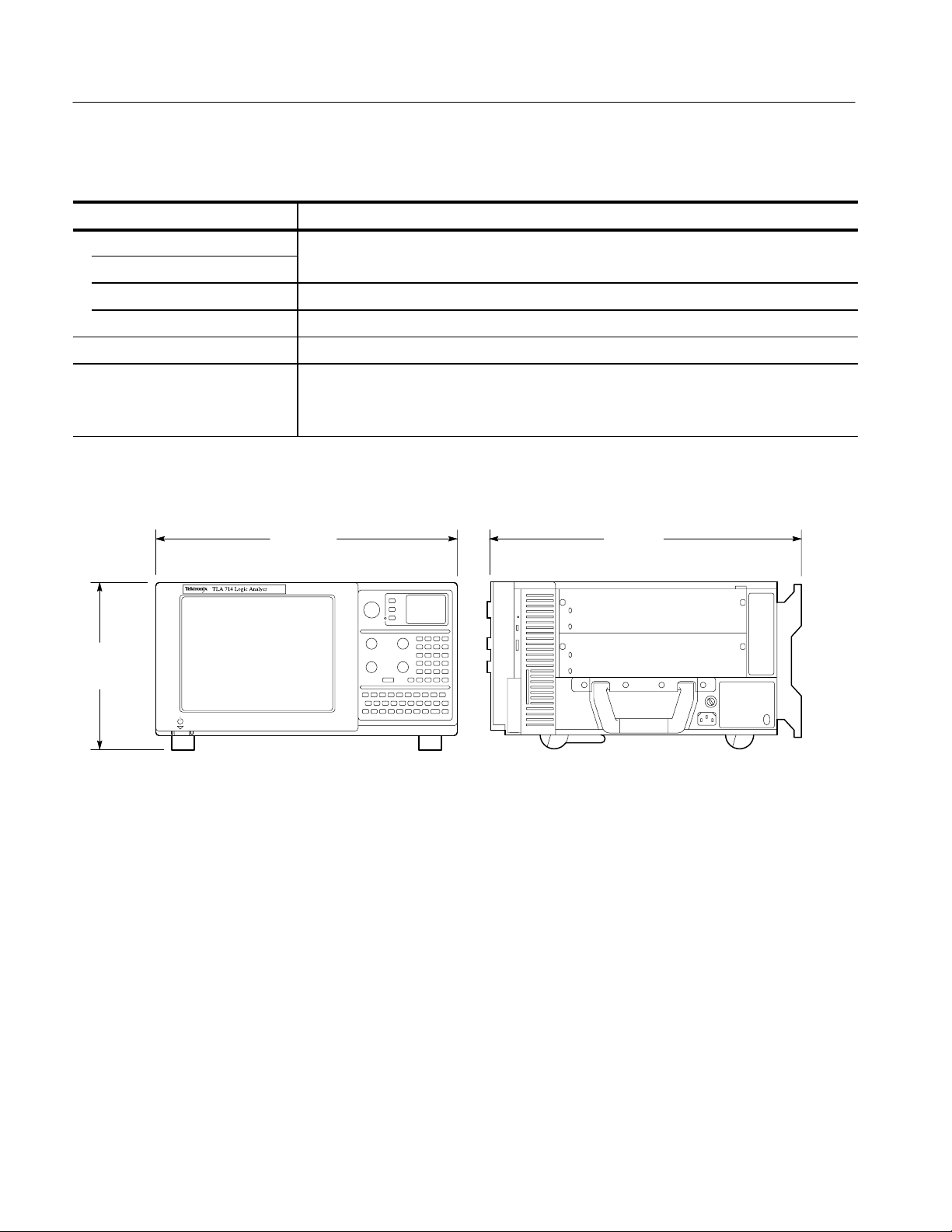
T able 1–11: Mechanical
Characteristic Description
Overall Dimensions (See Figure 1–1 for overall chassis dimensions)
Height (with feet) 9.25 in (23.5 cm)
Width 17 in (43.18 cm)
Depth 17.5 in (44.45 cm)
Weight 30 lbs 12 oz (13.9 kg) with no modules installed, two dual-wide slot covers, and empty pouch
Shipping Configuration 60 lbs 13 oz (27.58 kg) minimum configuration (no modules), with all standard accessories
86 lbs 9 oz (39.26 kg) full configuration, with two TLA 7P4 modules and standard accessories
(including probes)
17 in
(43.18 cm)
9.25 in
(23.5 cm)
Figure 1–1: Front and side views of the portable mainframe
17.5 in
(44.45 cm)
1–10
TLA 714 Color Portable Mainframe Service Manual
Page 31

Operating Information
Page 32

Page 33

Operating Information
This chapter contains information about operating the portable mainframe.
Installation
Refer to the TLA 700 Series Logic Analyzer Installation Manual for complete
information on how to install and configure the portable mainframe.
I/O and Memory Hardware
This section describes the I/O and memory hardware on the portable mainframe
including:
H 800 x 600 color display and front panel components
H Dual PC card ports
H Dual USB ports
H Rear-panel I/O ports
H Replaceable hard disk drive, CD ROM drive, floppy disk drive, and
SO DIMM memory.
Figure 2–1 shows the front panel. Figure 2–2 shows the rear panel.
Floppy disk
drive
Keyboard
Mouse
USB
Color display
Figure 2–1: TLA 714 portable mainframe front panel
Knobs
Glidepoint
CD–ROM
Front panel
keyboard
Replaceable
hard disk
drive
TLA 714 Color Portable Mainframe Service Manual
2–1
Page 34

Operating Information
Color LCD Display
Front Panel Keypad,
Knobs
Glidepoint Point Device
USB Port
The portable mainframe features a 10.4-inch diagonal, 600 X 800, flat-panel
LCD color display.
The front panel of the portable mainframe includes a QWERTY keyboard, a
hexadecimal numeric keypad, and five front panel knobs. The keypads are active
simultaneously with the standard external keyboard.
Front Panel Knobs. The front panel knobs include a large multi-function knob and
four smaller positioning/scale knobs. The multi-function knob is used primarily
for incrementing and decrementing values in selected menu boxes. The positioning and scale knobs (Vertical Position, Horizontal Position, Vertical Scale, and
Horizontal Scale) provide necessary control of DSO applications, as well as the
scrolling of logic analyzer displays.
The glidepoint device, vertically mounted on the front panel, can be used instead
of an external mouse when limited bench space is available. The glidepoint
device and a standard external mouse are active simultaneously.
There are two USB (universal serial bus) ports. The USB ports can be used for
any USB complaint device.
Mouse Port
Keyboard Port
PC Card Port
T able 2–1: USB (universal serial bus) pin assignments
Pin number Pin function Pin number Pin function
A1 Vcc B1 Vcc
A2 A DA TA – B2 B DA TA –
A3 A DA TA + B3 B DATA +
A4 GND B4 GND
The portable mainframe supports an external pointing device. The mouse
connector is a standard six-pin, PS/2-compliant DIN connector. The mouse port
can be connected to an external, standard PS/2-compliant three-button mouse.
The portable mainframe has an external keyboard port. The keyboard connector
is a standard six-pin PS/2-compliant DIN connector. The keyboard port can be
connected to an external, standard PS/2-compliant keyboard.
There are two PCMCIA card slots that support an industry standard Type I, II, or
III PCMCIA PC card.
2–2
TLA 714 Color Portable Mainframe Service Manual
Page 35

Operating Information
Replaceable
Hard Disk Drive
Fixed Hard Disk Drive
CD ROM Drive
Floppy Disk Drive
Memory SO DIMMs
There is one replaceable hard drive. Because of the speed at which the PC
industry evolves, the hard disk drive is subject to change. This service manual
lists the size of the hard disk drive available at the time the product was
introduced. Consult your Tektronix Sales Representative for the maximum hard
disk drive available.
It is possible to add a fixed hard disk drive to the TLA 714 mainframe which is
available through the TLA 7UP mainframe upgrade kit. Contact your Tektronix
representative for more information on available upgrades to your mainframe.
The portable mainframe has one CD ROM drive.
The portable mainframe has one standard 1/2 inch drive that supports 3.5 inch,
1.44 MByte, high-density/double-sided floppy disk media.
The portable mainframe utilizes 144-pin SO DIMM memory devices. The
memory devices must have gold pins.
Refer to the specifications for memory parameters.
External I/O BNCs
The portable mainframe has four test I/O BNC connectors on the rear panel (see
Figure 2–2) these connectors are labeled:
SYSTEM TRIG IN
SYSTEM TRIG OUT
EXTERNAL SIGNAL IN
EXTERNAL SIGNAL OUT
PC cards (2)
SYSTEM TRIG IN
SYSTEM TRIG OUT
EXTERNAL SIGNAL IN
EXTERNAL SIGNAL OUT
SVGA OUT port
COM port
LPT port
Figure 2–2: Portable mainframe rear panel
TLA 714 Color Portable Mainframe Service Manual
2–3
Page 36

Operating Information
SYSTEM TRIG IN Connector. The System Trigger Input is a TTL-compatible
signal input that is user definable in software. The System Trigger Input utilizes a
BNC connector. Refer to the
TLA 700 Series Logic Analyzer User Manual for
additional information.
SYSTEM TRIG OUT Connector. The System Trigger Output is a TTL-compatible
output signal that is user definable in software. The System Trigger Output
utilizes a BNC connector. Refer to the
TLA 700 Series Logic Analyzer User Manual
for additional information.
EXTERNAL SIGNAL IN Connector. The External Signal Input is a TTL-compatible
input signal that is user definable in software. The External Signal Input utilizes a
BNC connector. Refer to the
TLA 700 Series Logic Analyzer User Manual for
additional information.
EXTERNAL SIGNAL OUT Connector. The External Signal Output is a TTL-compatible output signal that is user definable in software. The System Trigger
Output utilizes a BNC connector. Refer to the
Manual for additional information.
TLA 700 Series Logic Analyzer User
SVGA Port
The SVGA OUT port supports an industry standard SVGA color monitor. The
connector is a 15-pin, sub-D SVGA-compliant connector. See Table 2–2 for pin
assignments.
T able 2–2: SVGA OUT pin assignments
Pin number Pin function Pin number Pin function
1 RED 2 GRN
3 BLU 4 NC
5 GND 6 GND
7 GND 8 GND
9 (KEY) 10 GND
11 NC 12 DDC DAT
13 HSYNC 14 VSYNC
15 DDD CLK
2–4
TLA 714 Color Portable Mainframe Service Manual
Page 37

Operating Information
COM Port
LPT Port
The COM port is an industry standary RS-232 serial port.
Pin number Pin function Pin number Pin function
1 DCD 2 RXD
3 TXD 4 DTR
5 GND 6 DSR
7 RTS 8 CTS
9 Ring Indicator
The LPT port is a parallel printer port. This parallel printer port supports standard
Centronics mode, Enhanced Parallel Port (EPP), or Microsoft high-speed mode
(ECP) and utilizes a 36-pin high density Centronics-compliant connector. See
Table 2–3 for pin assignments.
T able 2–3: LPT (parallel interface) pin assignments
Pin number Pin function Pin number Pin function
1 BUSY 19 GND
2 SLCT 20 GND
3 ACK* 21 GND
4 ERR* 22 GND
5 PE 23 GND
6 D0 24 GND
7 D1 25 GND
8 D2 26 GND
9 D3 27 GND
10 D4 28 GND
11 D5 29 GND
12 D6 30 GND
13 D7 31 GND
14 INIT* 32 GND
15 STB* 33 GND
16 SLIN* 34 GND
17 AFD* 35 GND
18 HI 36 H1
See IEEE specification P1284-C for pin connection definitions for other modes
TLA 714 Color Portable Mainframe Service Manual
2–5
Page 38

Operating Information
Operating System and Application Interface
The portable mainframe comes with the Microsoft Windows operating system
factory-installed. Operations and capabilities when running on the portable
mainframe are the same as with Microsoft Windows running on a high-performance personal computer. Windows Help is available from the Start menu of the
Windows Task Bar.
The portable mainframe also comes with the TLA 700 series application software
configured at the factory to launch after the logic analyzer boots up and the
operating system is running. The TLA 700 series application software controls
data acquisition and processing by the logic analyzer. The TLA 700 series
application software is included with the product. Refer to the
Installation Manual if you need to reinstall the TLA 700 series application
software.
TLA 700 Series
Diagnostics
Online Help
Most of the user information for operating the portable mainframe is available
through online help.
Refer to the TLA 700 series online help for more information on the individual
menus, icons, and fields within each window. You may also want to refer to the
TLA 700 Series Logic Analyzer User Manual for additional information.
Refer to your Microsoft Windows documentation for additional information on
using Windows help.
The portable mainframe contains the following diagnostics:
H BIOS diagnostic tests (automatic)
H TLA 700 series application software (automatic and manual)
H TLA 700 series mainframe diagnostics (manual)
H QA+Win32 (manual)
All diagnostics (both automatic and manually executed tests) are useful for
troubleshooting purposes.
2–6
The portable mainframe performs BIOS and TLA 700 series application
diagnostics for the mainframe and all installed modules every time you power on.
The diagnostics window displays when any of the diagnostic tests fail. To access
the diagnostics tests in the TLA 700 series application software, use the System
pull-down menu.
TLA 714 Color Portable Mainframe Service Manual
Page 39

Operating Information
In addition to Power-on Diagnostics, the Portable Mainframe also contains
mainframe diagnostics and QA+Win32 diagnostics for the PC hardware.
For more information about diagnostics, refer to the Maintenance chapter.
TLA 714 Color Portable Mainframe Service Manual
2–7
Page 40

Operating Information
2–8
TLA 714 Color Portable Mainframe Service Manual
Page 41

Theory of Operation
Page 42

Page 43

Theory of Operation
This section provides a brief overview of the board level theory of operation for
the portable mainframe. Refer to page 6–2 for a functional block diagram.
Portable Mainframe
The portable mainframe contains the following major components:
Power Supply
Backplane
Controller Board
Front Panel
Interface Board
Front Panel Controller
Board
The power supply provides all voltages and currents to the portable mainframe.
The power supply connects to the backplane at P400 and P401.
The backplane connects the power supply secondary to the remainder of the
system, including the fans, distributes the precision 10-MHz (CLK10) system
clock, and supports all communication between the instrument modules.
The controller board provides the portable mainframe with a high-performance
PC-based controller architecture, and interfaces to the backplane bus and front
panel. The controller board mounts vertically on the left side of the instrument
and connects to the back of the backplane. The controller board provides I/O to
the rear panel and is the source of the 10-MHz (CLK10) system clock.
The front panel interface board interconnects the controller board, the flat-panel
display, the floppy disk drive, the front-panel keypad and glidepoint, dual USB
ports, and the external mouse and keyboard ports. Dual 50-pin cables connect the
front panel interface board to the controller board. The interface board also
supplies the PC speaker.
The front panel controller board combines signals from the front-panel hex
keypad, the front-panel QWERTY keypad, and an external keyboard to generate
or receive standard keyboard scan-codes from the controller board.
Mechanical Chassis
TLA 714 Color Portable Mainframe Service Manual
The mechanical chassis provides the mechanical support structure for the
instrument, and includes the cooling system, the modular-card cage, the EMI
shielding system, and all the subsystems previously listed.
3–1
Page 44

Theory of Operation
3–2
TLA 714 Color Portable Mainframe Service Manual
Page 45

Maintenance
Page 46

Page 47

Maintenance
Preparation
Preventing ESD
This chapter provides procedures for inspecting and cleaning the portable
mainframe, removing and replacing internal chassis components, and isolating
problems to the board or replacement part level.
To repair, you must exchange or replace the failed part; this manual does not
provide component-level procedures for isolating components on the failed part.
The information in this chapter is designed for use by qualified service personnel. Read the Safety Summary at the front of this manual before attempting any
procedures in this chapter. Refer to the Operating Information chapter for
information on the location of controls, indicators, and connectors used with the
chassis.
When performing any service which requires internal access to the portable
mainframe, adhere to the following precautions to avoid damaging internal
circuit boards and their components due to electrostatic discharge (ESD).
CAUTION. Many components within the chassis are susceptible to staticdischarge damage. Service the chassis only in a static-free environment.
Observe standard handling precautions for static-sensitive devices while
servicing the chassis.
Always wear a grounded wrist strap, or equivalent, while servicing the chassis.
1. Minimize handling of static-sensitive circuit boards.
2. Transport and store static-sensitive circuit boards in their static protected
containers or on a metal rail. Label any package that contains static-sensitive
boards.
3. Discharge the static voltage from your body by wearing a grounded antistatic
wrist strap while handling these circuit boards. Do service of static-sensitive
circuit boards only at a static-free work station.
4. Nothing capable of generating or holding a static charge should be allowed
on the work station surface.
TLA 714 Color Portable Mainframe Service Manual
4–1
Page 48

Maintenance
5. Handle circuit boards by the edges when possible.
6. Do not slide the circuit boards over any surface.
7. Avoid handling circuit boards in areas that have a floor or work-surface
WARNING. To avoid electric shock, always power off the chassis and disconnect
the power cord before cleaning or servicing the chassis.
Inspection and Cleaning
The portable mainframe is inspected mechanically and electrically before
shipment. It should be free of marks or scratches and should meet or exceed all
electrical specifications. To confirm this, inspect the chassis for physical damage
incurred during transit. Retain the chassis packaging in case shipment for repair
is necessary. If there is damage or deficiency, contact your local Tektronix
representative.
covering capable of generating a static charge.
Interior Cleaning
Exterior Cleaning
Cleaning procedures consist of exterior and interior cleaning of the chassis.
Clean the chassis as needed, based on the operating environment. Refer to the
appropriate module service manuals for information on cleaning individual
TLA 700 Series modules.
Use a dry, low-velocity stream of air to clean the interior of the chassis. Use a
soft-bristle, non-static-producing brush for cleaning around components. If you
must use a liquid for minor interior cleaning, use a 75% isopropyl alcohol
solution and rinse with deionized water.
Clean the exterior surfaces of the chassis with a dry lint-free cloth or a softbristle brush. If any dirt remains, use a cloth or swab dipped in a 75% isopropyl
alcohol solution. Use a swab to clean narrow spaces around controls and
connectors. Do not use abrasive compounds on any part of the chassis that may
damage the chassis.
Clean the On/Standby switch using a dampened cleaning towel. Do not spray or
wet the switch directly.
4–2
TLA 714 Color Portable Mainframe Service Manual
Page 49

Maintenance
CAUTION. Avoid getting moisture inside the chassis during exterior cleaning; use
just enough moisture to dampen the cloth or swab.
Do not wash the front-panel On/Standby switch. Cover the switch while washing
the chassis.
Use only deionized or distilled water when cleaning. Use a 75% isopropyl
alcohol solution as a cleanser and rinse with deionized or distilled water.
Do not use chemical cleaning agents; they may damage the chassis. Avoid
chemicals that contain benzene, toluene, xylene, acetone, or similar solvents.
Flat Panel Display
Cleaning
The portable mainframe display is a soft plastic display and must be treated with
care during cleaning.
CAUTION. Improper cleaning agents or methods can damage the flat panel
display.
Avoid using abrasive cleaners or commercial glass cleaners to clean the display
surface.
Avoid spraying liquids directly on the display surface.
Avoid scrubbing the display with excessive force.
Clean the flat panel display surface by gently rubbing the display with a
clean-room wipe (such as Wypall Medium Duty Wipes, #05701, available from
Kimberly-Clark Corporation).
If the display is very dirty, moisten the wipe with distilled water or a 75%
isopropyl alcohol solution and gently rub the display surface. Avoid using excess
force or you may damage the plastic display surface.
TLA 714 Color Portable Mainframe Service Manual
4–3
Page 50

Maintenance
4–4
TLA 714 Color Portable Mainframe Service Manual
Page 51

Removal and Installation Procedures
This section contains procedures for removal and installation of all mechanical
and electrical field-replaceable parts.
Preparation
WARNING. Before performing this or any other procedure in this manual, read
the Safety Summary found at the beginning of this manual.
To prevent possible injury to service personnel or damage to the portable
mainframe, read Installation in Chapter 2, and Preventing ESD on page 4–1 in
this section.
WARNING. Dangerous voltages may be present.
Before performing any procedure in this subsection, disconnect the power cord
from the line voltage source.
General Instructions
Failure to do so could cause serious injury or death.
NOTE. Read the following general instructions before removing a part.
Following these instructions helps ensure that you remove the part to be serviced
while removing the minimum number of additional parts.
First read over the Summary of Procedures that follows to understand how the
procedures are grouped. Then see Table 4–1 for a list of the tools needed to
remove and install replaceable parts in this mainframe.
If you are removing a part for service, begin by looking up the procedure for that
part. If any procedures are listed as required in advance in order to gain access to
the part, perform those procedures first.
TLA 714 Color Portable Mainframe Service Manual
4–5
Page 52

Removal and Installation Procedures
Equipment Required
Most parts in this mainframe can be removed with a screwdriver with a T-15
Torx tip.
T able 4–1: Tools required for part removal
Name
Screwdriver with a T-15 Torx tip
Screwdriver with a T-10 Torx tip
Flat Blade Screwdriver
Phillips screwdriver with a #1 tip
Pliers
Side cutters
Scribe or jeweler’s screwdriver
Cable ties
4–6
TLA 714 Color Portable Mainframe Service Manual
Page 53

Exploded View
Left side cover
Removal and Installation Procedures
Figure 4–1 shows the locations of the parts of the portable mainframe.
Accessories
pouch
Top cover
Chassis fan tray
Cord-wrap feet
Display assembly
Trim ring
Front cover
Figure 4–1: External parts
Front panel control
assembly
CD–ROM Drive
Power supply
Right side cover
Bottom cover
Replaceable
hard disk drive
TLA 714 Color Portable Mainframe Service Manual
4–7
Page 54

Removal and Installation Procedures
Removing the Replaceable Hard Disk Drive
CAUTION. Do not remove the replaceable hard disk drive when the mainframe is
powered on.
The replaceable hard disk drive may be permanently damaged if it is removed
while the mainframe is powered on.
Always power down the mainframe before removing the replaceable hard disk
drive.
Verify that the chassis is powered down.
The hard disk drive cartridge is removed by depressing it. This will release the
latch. Pull on the removable hard disk drive to remove it from the chassis. Refer
to Figure 4–3 and 4–4.
4–8
Figure 4–2: Depress the latch
TLA 714 Color Portable Mainframe Service Manual
Page 55

Removal and Installation Procedures
Figure 4–3: Unlatching the hard disk drive cartridge
Figure 4–4: Removing the hard disk drive cartridge
TLA 714 Color Portable Mainframe Service Manual
4–9
Page 56

Removal and Installation Procedures
Removing the Hard Disk Drive From The Cartridge
To remove the hard disk drive from the cartridge, refer to Figure 4–5 and follow
these steps:
1. Remove the four screws that fasten the hard disk drive to the cartridge.
2. Carefully remove the hard disk drive from the cartridge, and remove the
cable assembly from the connector on the hard disk drive.
Remove 4 screws
Trim Ring
Removal
Figure 4–5: Removing the hard disk drive from the cartridge
You will need a flat-bladed screwdriver (or other small prying tool) to remove
the trim ring.
Use the following procedure to remove the trim ring:
1. Set the mainframe with the cord-wrap feet on the work surface and the
bottom facing you.
2. Grasp the trim ring by its bottom edge and pull toward you to detach the
three plastic snaps. (Alternatively, you can use a flat-bladed screwdriver or
other small prying tool to help you detach the snaps.) Then, swing the
bottom of the ring upward and work the rest of the ring off the front panel.
4–10
TLA 714 Color Portable Mainframe Service Manual
Page 57

Removal and Installation Procedures
Installation
Use the following procedure to replace the trim ring:
3. Replace the trim ring on the front panel. Start at the top edge and work
around to the bottom until the three plastic snaps engage. Press the trim ring
down all around the edges until it is completely seated.
When removing the trim ring,
grasp its bottom edge and flex
it toward you before pulling
upward.
Trim ring
Figure 4–6: Trim ring removal
TLA 714 Color Portable Mainframe Service Manual
4–11
Page 58

Removal and Installation Procedures
Flat Panel Display Assembly
You will need a screwdriver with a size T-15 Torx tip to perform this procedure.
Removal
Use the following procedure to remove the flat panel display assembly:
1. Do the Trim Ring removal procedure on page 4–10.
2. Remove the five screws that attach the flat panel display assembly to the
mainframe: two screws at the bottom of the assembly on the front of the
instrument, two screws on the top, and one screw on the left side. (See
Figure 4–7 on page 4–13).
3. Lift the bottom edge of the flat panel display assembly and rotate it upward
and off the front face of the mainframe.
4. Detach the cable connecting the flat panel display assembly to connector
J209 on the front panel interface board.
5. Detach the five pin display backlight connector.
4–12
TLA 714 Color Portable Mainframe Service Manual
Page 59

Flat panel display
assembly
Removal and Installation Procedures
Remove screws (5)
Disconnect
the cable
Installation
Display
backlight
cable
Figure 4–7: Flat panel display assembly removal
Use the following procedure to reinstall the flat panel display assembly:
1. Reattach the cable connecting the flat panel display assembly to the interface
board.
2. Reattach the display backlight cable.
3. Reinstall the flat panel display assembly by first inserting the top edge and
then rotating it downward into position. (Be sure the tabs are engaged at the
top of the assembly. Insert the five screws that attach the flat panel display
assembly to the mainframe: two screws at the bottom of the assembly on the
front of the instrument, two screws on the top, and one screw on the left side.
(See Figure 4–7 on page 4–13).
4. Do the Trim Ring installation on page 4–11.
TLA 714 Color Portable Mainframe Service Manual
4–13
Page 60

Removal and Installation Procedures
Floppy Disk Drive
You will need a screwdriver with a size T-15 Torx tip to perform this procedure.
Removal
Installation
Use the following procedure to remove the floppy disk drive:
1. Do the Trim Ring Removal procedure, steps 1-5, on page 4–10.
2. Do the Flat Panel Display Assembly removal procedure, page 4–12.
3. Detach the data cable from J103 on the front panel interface board; there is a
release latch on both the floppy drive and the interface board connectors.
4. Remove the two screws securing the floppy disk drive to the chassis.
5. Remove the floppy disk drive.
6. Remove the cable from the floppy disk drive.
Use the following procedure to reinstall the floppy disk drive:
1. Attach the data cable to the floppy disk drive.
2. Reposition the disk drive.
3. Insert the two screws securing the floppy disk drive to the chassis.
4. Attach the data cable to J103 on the interface board.
5. Do the Front Panel Display Assembly installation procedure, page 4–13.
6. Do the Trim Ring installation on page 4–11.
Front Panel Interface Board
You will need a screwdriver with a T-15 Torx head to perform this procedure.
Removal
4–14
The front panel interface board is located under the front panel display. Use the
following procedure to remove the interface board:
1. Do the Trim Ring Removal procedure, steps 1-5, on page 4–10.
2. Do the Flat panel Display Assembly removal procedure, page 4–12.
3. Detach the ribbon cables at J100, J101, J209, J102, and J103.
4. Remove the one screw securing the interface board, and the two screws on
the side panel.
TLA 714 Color Portable Mainframe Service Manual
Page 61

Removal and Installation Procedures
5. Grasp the board and slide the board to the right (toward the front panel
control assembly) and lift the board out.
Installation
Use the following procedure to reinstall the interface board:
1. Reposition the interface board on the mounting pegs, and slide it to the left
(i.e., away from the front panel control assembly).
2. Insert the screw securing the interface board to the front, and the two screws
securing the interface board to the side panel.
3. Reattach cables at J100, J101, J209, J102, and J103.
4. Do the Display Assembly installation procedure, page 4–13.
5. Do the Trim Ring installation on page 4–11.
Front Panel Control Assembly
You will need a screwdriver with a size T-15 Torx tip to perform this procedure.
Removal
Use the following procedure to remove the front panel control assembly:
1. Do the Trim Ring Removal procedure on page 4–10.
2. Remove the flat panel display as shown on page 4–12.
3. Remove the four screws that attach the front panel control assembly to the
mainframe: two at the bottom of the assembly on the front of the instrument,
two on the top. (See Figure 4–8 on page 4–16).
TLA 714 Color Portable Mainframe Service Manual
4–15
Page 62

Removal and Installation Procedures
Remove screws (2)
Disconnect
the cable
Remove 2 short
screws
Front panel control
assembly
Disconnect
the cable
Figure 4–8: Front-panel control assembly removal
4. Lift the bottom edge of the front control panel assembly and rotate it upward
and off the front face of the mainframe.
5. Detach the two ribbon cables connecting the front panel panel assembly and
the CD ROM to the interface board.
NOTE. Procedures for removing the knobs, elastomeric keypad, and Front Panel
Control Board are found in Procedures for Internal Parts, which begins on page
4–33.
4–16
TLA 714 Color Portable Mainframe Service Manual
Page 63

Removal and Installation Procedures
Installation
Front Panel Knobs
Removal
Use the following procedure to install the front panel control assembly:
1. Reattach the cable connecting the front panel control assembly to the
interface board.
2. Reinstall the front panel control assembly by first inserting the top edge and
then rotating it downward into position. (Be sure the tabs are engaged at the
top of the assembly. Insert the five screws that attach the front panel control
assembly to the mainframe: two at the bottom of the assembly on the front of
the instrument, two on the top, and one on the right side. (See Figure 4–8 on
page 4–16).
3. Do the Trim Ring installation on page 4–11.
No tools are needed to remove or replace a front panel knob on the portable
mainframe.
To remove a front panel knob, grasp the knob and pull it straight out from the
front panel.
Installation
To reinstall a knob, align the knob to a shaft and push in as far as it will go.
TLA 714 Color Portable Mainframe Service Manual
4–17
Page 64

Removal and Installation Procedures
CD ROM Drive
The CD ROM drive is attached to the underside of the front panel control
assembly. You will need a screwdriver with a size T-15 and T-10 Torx
CAUTION. The CD ROM drive uses a laser.
Use of procedures other then those specifically listed herein may result in
hazardous radiation exposure.
Do not attempt to open the CD ROM drive covers, or attempt any type of repair
on the CD ROM drive.
Refer all servicing of the CD ROM drive to qualified personnel.
tip.
Removal
Installation
Use the following procedure to remove the CD ROM drive:
1. Do the Trim Ring removal procedure, steps 1-5, on page 4–10.
2. Do the Display Assembly removal procedure on page 4–12.
3. Do the Front Panel Control Assembly removal on page 4–15.
4. Remove the five screws that attach the CD ROM drive to the front panel
control assembly: three from the left side, two from the right side.
Use the following procedure to reinstall the CD ROM drive:
1. Reposition the CD ROM drive within the bracket.
2. Install the five screws that attach the CD ROM drive to the front panel
control assembly: three from the left side, two from the right side.
3. Do the Front Panel Control Assembly install on page 4–17.
4. Do the Display Assembly installation procedure, page 4–13.
5. Do the Trim Ring installation on page 4–11.
4–18
TLA 714 Color Portable Mainframe Service Manual
Page 65

Bottom Cover
Removal and Installation Procedures
Removing the bottom cover should only be necessary when replacing a flip stand
or rear foot. You may also need to loosen the mounting screws on one side of the
bottom cover to remove or replace either side cover or to remove the power
supply.
Removal
Installation
You will need a screwdriver with a size T-15 Torx
Use the following procedure to remove the bottom cover:
1. Set the mainframe with the cord-wrap feet on the work surface and the
bottom facing you.
2. Remove the four screws that attach the bottom cover to the mainframe. (See
Figure 4–6 on page 4–11.)
3. Lift bottom cover off.
Reposition the bottom cover on the bottom surface of the portable mainframe.
Insert the four screws that attach the bottom cover to the mainframe. (See
Figure 4–6 on page 4–11.)
tip to perform this procedure.
TLA 714 Color Portable Mainframe Service Manual
4–19
Page 66

Removal and Installation Procedures
Top Cover
You will need a screwdriver with a size T-15 Torx tip to perform this procedure.
Removal
Installation
Use the following procedure to remove the top cover:
1. Set the mainframe with the bottom on the work surface and the front facing
you.
2. Unsnap the accessories pouch from the top cover.
3. Do the Trim Ring removal procedure on page 4–10.
4. Remove the four screws that attach the top cover to the mainframe. (See
Figure 4–9 on page 4–21.)
5. Lift the top cover off.
Use the following procedure to reinstall the top cover:
1. Reposition the top cover on the portable mainframe.
2. Insert the four screws that attach the top cover to the mainframe. (See
Figure 4–9 on page 4–21.)
3. Do the Trim Ring installation procedure on page 4–10.
4. Reattach the accessories pouch to the top cover. (It snaps on.)
4–20
TLA 714 Color Portable Mainframe Service Manual
Page 67

Left side
cover
Removal and Installation Procedures
Screws (4)
Top cover
Left Side Cover
Removal
Screws (2)
Right side cover
Figure 4–9: T op and side cover removal
No screws attach the left side cover to the mainframe. However, you must loosen
the two screws closest to the left side of the bottom cover in order to remove the
left side cover.
You will need a screwdriver with a size T-15 Torx
tip to perform this procedure.
Use the following procedure to remove the left side cover:
1. Do the Trim Ring removal procedure, steps 1-5, on page 4–10.
2. Do the Top Cover removal procedure on page 4–20.
3. Loosen the two screws on the bottom cover closest to the left side of the
mainframe. (See Figure 4–6 on page 4–11.)
4. Remove the left side cover.
TLA 714 Color Portable Mainframe Service Manual
4–21
Page 68

Removal and Installation Procedures
Installation
Right Side Cover
Removal
Reposition the left side cover and tighten the two bottom cover screws nearest
the left side of the mainframe. Do the Top Cover installation procedure as shown
on page 4–20.
You will need a screwdriver with a size T-15 Torx tip to perform this procedure.
Use the following procedure to remove the left side cover:
1. Remove any installed modules from the portable mainframe.
2. Do the Trim Ring removal procedure, steps 1-5, on page 4–10.
3. Do the Line Cord and Line Fuse removal procedure, page 4–23.
4. Do the Top Cover removal procedure, page 4–20.
5. Loosen the two screws on the bottom cover closest to the right side of the
mainframe. (See Figure 4–6 on page 4–11.)
6. Remove the two screws that attach the right side cover to the power supply.
(See Figure 4–9 on page 4–21.)
Installation
7. Remove the right side cover.
Use the following procedure to reinstall the right side cover:
1. The two screws near the right side of the bottom cover should be loosely
fastened.
2. Reseat the right side cover in the groove of the bottom cover.
3. Insert the two screws that attach the right side cover to the power supply.
4. Tighten the two bottom cover screws nearest the right side of the mainframe.
5. Do the Top Cover installation procedure, page 4–20.
6. Do the Trim Ring installation procedure, page 4–10
7. Do the Line Cord and Line Fuse installation procedure, page 4–23.
4–22
TLA 714 Color Portable Mainframe Service Manual
Page 69

Line Cord and Line Fuse
You will need a flat-bladed screwdriver to perform this procedure.
Removal and Installation Procedures
Removal
Installation
Use the following procedure to remove the line cord and line fuse:
1. Unplug the instrument from power.
2. Set the mainframe with the bottom on the work surface and the right side
facing you. If you are replacing the line fuse, do the next step; if you are
replacing the line cord only, skip to step 4.
3. Find the fuse cap on the right side cover. (See Figure 4–10 on page 4–24.)
Remove the fuse cap by turning it counterclockwise using a flat-bladed
screwdriver, and then remove the line fuse.
4. Find the line cord on the right side cover. (See Figure 4–10 on page 4–24.)
Unplug the line cord from its receptacle. Grasp the line cord on either side of
the line cord retaining clamp. Rotate the line cord 90 degrees counterclockwise. Pull the line cord and clamp away from the side panel mounting hole
to complete the removal.
Use the following procedure to reinstall the line fuse and line cord:
1. If you are replacing the line fuse, insert it into the line fuse receptacle. If you
are not replacing the line fuse, skip to step 3.
2. Replace the fuse cap by turning it clockwise using a flat bladed screwdriver.
3. Insert the line cord and retaining clamp into the mainframe side panel
mounting hole, with the line cord oriented up and down.
4. Rotate the line cord 90 degrees counterclockwise.
5. Plug the line cord into its receptacle.
TLA 714 Color Portable Mainframe Service Manual
4–23
Page 70

Removal and Installation Procedures
3 Pull
2 Rotate
Line fuse
Fuse cap
Figure 4–10: Line cord and line fuse removal
1 Unplug
4–24
TLA 714 Color Portable Mainframe Service Manual
Page 71

Power Supply
Removal and Installation Procedures
You will need a screwdriver with a size T-15 Torx tip to perform this procedure.
Removal
Use the following procedure to remove the power supply:
1. Do the removal procedures for Bottom Cover (page 4–19), Top Cover
(page 4–20), and Right Side Cover (page 4–22).
Remove screws (4)
EMI shield
Power supply
Power supply panel
Remove screws (4)
Remove power
supply screws (4)
Remove corner screws (4)
Figure 4–11: Power supply removal
2. Remove the four screws from the right side and the four screws from the
bottom that secure the power supply to the chassis.
3. Pull on the handle to remove the power supply from the chassis.
TLA 714 Color Portable Mainframe Service Manual
Right side cover
Remove
screws (2)
4–25
Page 72

Removal and Installation Procedures
4. Remove the handle and power supply panel before packaging the power
NOTE. Replacement power supplies do not come equipped with a power supply
panel or handle.
supply for exchange.
Installation
Rear Chassis Fan Tray
Removal
Use the following procedure to reinstall the power supply:
1. Install the power supply panel and handle onto the replacement power
supply.
2. Insert the power supply into the chassis. Press firmly to make sure the power
supply is fully seated.
3. Insert the four screws on the right side and the four screws on the bottom
that secure the power supply to the chassis.
4. Do the installation procedures for Bottom Cover (page 4–19), then Right Side
Cover (page 4–22), and then Top Cover (page 4–20).
You will need a screwdriver with a size T-15 Torx tip to perform this procedure.
Use the following procedure to remove the rear chassis fan tray:
1. Set the mainframe so that the bottom is on the work surface and the rear
chassis fan tray faces you.
4–26
2. Remove the four screws located within the cord-wrap feet that secure the rear
chassis fan tray to the mainframe. (See Figure 4–12 on page 4–27.)
3. Grasp the left cord-wrap foot (facing the fan tray) and swing the left side of
the fan tray away from the mainframe.
4. Disconnect the cable connecting the rear chassis fan tray to the backplane
board.
5. Remove the rear chassis fan tray.
TLA 714 Color Portable Mainframe Service Manual
Page 73

Removal and Installation Procedures
Disconnect
Fan tray
Installation
Cord-wrap feet
Remove
screws (4)
Figure 4–12: Rear chassis fan tray removal
Use the following procedure to reinstall the rear chassis fan tray:
1. Redress the cable connecting the rear chassis fan tray to the backplane board
if necessary.
2. Reconnect the cable connecting the rear chassis fan tray to the backplane
board.
3. Reposition the rear chassis fan tray.
4. Reposition the cord-wrap feet (they snap into holes on the rear chassis fan
tray), and insert the four screws that secure the rear chassis fan tray to the
mainframe.
TLA 714 Color Portable Mainframe Service Manual
4–27
Page 74

Removal and Installation Procedures
Individual Fans
You will need a screwdriver with a size T-15 Torx tip, a Philips screwdriver,
pliers, a side cutter, and a scribe or jeweler’s screwdriver or other small, pointed
tool to perform this procedure.
Removal
Use the following procedure to remove an individual fan from the rear chassis
fan tray:
1. Do the Rear Chassis Fan Tray removal procedure, page 4–26.
2. Remove the screw that secures the hold down brackets to the rear chassis fan
tray. (See Figure 4–13 on page 4–29.) If you are replacing one of the two
fans nearest the cable connector, you need remove only one of the hold-down
brackets. Otherwise, remove two.
3. Use the pliers to gently straighten the metal tabs holding the fan to the rear
chassis fan tray.
4. Lift the fan from the rear chassis fan tray.
5. Make note of the fan cable dress and remove the tie holding the cables
together near the connector. Remove the cable tie(s) if necessary.
6. Remove the fan wires from the cable connector. (Pay attention to the wire
color locations for reinstallation.) Use a scribe or jeweler’s screwdriver to
gently push down the “finger” of metal that secures (latches) the wire end
into the connector. (See insert, Figure 4–13 on page 4–29.) At the same time,
pull gently on the wire until it comes out of the connector.
4–28
Installation
Use the following procedure to reinstall the individual fans from the rear chassis
fan tray:
1. Reinsert the fan wires into the cable connector. Be sure to insert the
2. Position the fan onto the rear chassis fan tray.
3. Gather the fan cables together, tie them together with a cable tie, and
4. Use a pair of pliers to gently bend the metal tabs that hold the fan to the rear
(color–coded) wires into the same locations as they were removed from in
step 6, above. The “finger” of metal that secures the wire end into the
connector should be pointed up and outward for it to lock into place. (See
insert, Figure 4–13 on page 4–29.)
position them so that they do not interfere with any fan blades.
chassis fan tray until the fan is held firmly in position.
TLA 714 Color Portable Mainframe Service Manual
Page 75

Removal and Installation Procedures
5. Attach the hold-down bracket(s) to the rear chassis fan tray.
6. Do the Rear Chassis Fan Tray installation procedure, page 4–27.
Screw
Hold-down bracket
Fan
Bend
tabs
Cable tie
Figure 4–13: Individual fan removal
Latch
TLA 714 Color Portable Mainframe Service Manual
4–29
Page 76

Removal and Installation Procedures
Flip Stands and Rear Feet
You will need a screwdriver with a size T-15 Torx tip and a small Philips
screwdriver to perform this procedure.
Removal
Use the following procedure to remove the flip stands and rear feet:
1. Set the mainframe so the rear panel is on the work surface and the bottom
faces you.
2. Do the Bottom Cover removal procedure, page 4–19.
3. Remove the two screws attaching the flip stand or rear foot to the bottom
cover. (See Figure 4–14 on page 4–30.)
Remove
screws (2)
4–30
Installation
Rear feet
Flip stands
Figure 4–14: Flip stand and rear feet removal
Reattach the flip stand or rear foot to the bottom cover. Do the Bottom Cover
installation procedure as shown on page 4–19.
TLA 714 Color Portable Mainframe Service Manual
Page 77

Cord Wrap Feet
Removal and Installation Procedures
You will need a screwdriver with a size T-15 Torx tip to perform this procedure.
Fan tray
Removal
Use the following procedure to remove the cord-wrap feet:
1. Set the mainframe so the bottom is on the work surface and the rear panel
faces you.
2. Do the Rear Chassis Fan Tray removal procedure, page 4–26.
3. Orient the chassis fan tray so that the cord-wrap feet are on the bottom and
the fans are on the top.
4. Press outward to unlatch the two tabs that connect each cord-wrap foot to the
chassis fan tray. (See Figure 4–15 on page 4–31.)
5. Remove the cord-wrap feet.
Press tabs
outward
Cord-wrap feet
Figure 4–15: Cord-wrap feet removal
Installation
Push the cord-wrap feet into the holes in the rear chassis fan tray to snap them
into position. Do the Rear Chassis Fan Tray installation procedure as shown on
page 4–27.
TLA 714 Color Portable Mainframe Service Manual
4–31
Page 78

Removal and Installation Procedures
Handle
You will need a screwdriver with a size T-15 Torx tip and a small flat-bladed
screwdriver to allow you to remove the front panel trim ring prior to removing
the handle.
Removal
Set the mainframe so the bottom is on the work surface and the right side (the
side with the handle) faces you.
Do the Right Side Cover removal procedure, page 4–22.
Remove the two inner screws connecting the handle to the power supply. (See
Figure 4–16 on page 4–32) and then lift off the plastic handle mount and handle.
4–32
Installation
Remove inner screws (2)
Figure 4–16: Handle removal
Attach the handle and plastic handle mount to the power supply. Do the Right
Side Cover installation procedure as shown on page 4–22.
TLA 714 Color Portable Mainframe Service Manual
Page 79

Procedures for Internal Parts
Figure 4–17 on page 4–34 shows the locations of the internal parts of the
portable mainframe. Procedures for removing and replacing these parts are
presented in the following order:
H Controller board
H SO DIMMs (RAM)
H Backplane board
H Front panel control board
H Front Panel interface board
H Glidepoint Assembly and Elastomeric Keypad
Controller Board
Removal and Installation Procedures
Removal
You will need a screwdriver with a size T-15 Torx tip to perform this procedure.
Use the following procedure to remove the controller board:
1. Locate the controller board in the locator diagram Internal parts,
Figure 4–17 on page 4–34.
2. Set the mainframe so the bottom is on the work surface and the left side
faces you.
3. Do the Left Side Cover removal procedure, page 4–21.
4. Remove the eight screws securing the EMI shield to the chassis (see
Figure 4–17 on page 4–34), and then lift off the EMI shield.
5. Detach the three cables located near the bottom front corner of the controller
board.
6. Remove the center screw from the controller board.
7. Remove the two screws securing the controller board to the chassis at the
back panel.
8. Pull firmly on the rear panel until the controller board disconnects from the
backplane board.
TLA 714 Color Portable Mainframe Service Manual
4–33
Page 80

Removal and Installation Procedures
Rear panel
Hard disk
drive
Figure 4–17: Internal parts
Installation
Front Panel
Interface board
RAM
EMI shield
Backplane
board
Controller
board
Floppy disk
drive
Use the following procedure to reinstall the controller board:
1. Reposition the controller board, and then push firmly on the backplane bus
connector until the board is fully seated in the connectors on the backplane
board.
2. Insert the center screw into the controller board.
3. Insert the two screws securing the controller board to the chassis at the back
panel.
4–34
4. Reattach the three cables located near the bottom front corner of the
controller board.
5. Reposition the EMI shield, and then insert the eight screws that secure it to
the chassis.
TLA 714 Color Portable Mainframe Service Manual
Page 81

Main Memory
Removal and Installation Procedures
6. Do the Left Side Cover installation procedure, page 4–22.
Refer to the TLA 700 Series Performance Verification and Adjustment manual
for post-repair calibration procedures.
You will need a screwdriver with a size T-15 Torx tip to perform this procedure.
Removal
Installation
Use the following procedure to remove the RAM:
1. Locate the SO DIMM module in the locator diagram Internal parts,
Figure 4–17 on page 4–34.
2. Set the mainframe so the bottom is on the work surface and the left side
faces you.
3. Do the Left Side Cover removal procedure, page 4–21.
4. Remove the two screws securing the EMI shield to the chassis, and then lift
off the EMI shield.
5. Press outward on the clips holding each SO DIMM module to the controller
board, and then lift off the module board.
Use the following procedure to install new SO DIMM module(s):
CAUTION. SO DIMM modules must have gold plated contacts.
Use of SO DIMM modules that do not have gold plated contacts will result in
eventual failure of the SO DIMM module.
Always use SO DIMM modules with gold plated contacts.
1. Insert the new SO DIMM module. Press down gently until the clips that hold
the modules to the controller board snap into place.
2. Reposition the EMI shield, and then insert the two screws that secure it to
the chassis.
3. Do the Left Side Cover installation procedure, page 4–22.
TLA 714 Color Portable Mainframe Service Manual
4–35
Page 82

Removal and Installation Procedures
Backplane Board
You will need a screwdriver with a size T-15 Torx tip to perform this procedure.
Removal
Installation
Use the following procedure to remove the backplane board:
1. Remove all modules installed in the portable mainframe.
2. Locate the backplane board in the locator diagram Internal parts, Fig-
ure 4–17 on page 4–34.
3. Do the Controller Board removal procedure, page 4–33.
4. Remove the seven remaining screws that secure the backplane board to the
chassis.
5. Pull on the edges of the board nearest the front and rear surfaces of the
mainframe to remove the backplane board from the chassis.
6. Detach cable J500.
Use the following procedure to reinstall the backplane board:
1. Reattach cable J500.
2. Reposition the backplane board, and insert the screws that secure the
backplane board to the chassis.
3. Do the Controller Board installation procedure, page 4–34.
4. Reinstall any modules removed from the portable mainframe.
Front Panel Control Board
You will need a screwdriver with a size T-15 Torx tip and a flat-bladed screwdriver or other small prying tool to perform this procedure.
Removal
4–36
Use the following procedure to remove the front panel control board:
1. Locate the front panel control board in the locator diagram Front panel
2. Do the Front Panel Control Assembly removal procedure (page 4–15).
3. Remove the knobs from the front of the front panel control assembly.
4. Detach the glidepoint cable at J100.
control assembly parts locations, Figure 4–18 on page 4–37.
TLA 714 Color Portable Mainframe Service Manual
Page 83

Removal and Installation Procedures
5. Remove the six screws that attach the front panel control board to the front
panel control assembly.
CD – ROM
Remove
screws (6)
Front panel
control
board
Use rubber pull points
to remove/attach
elastomeric keypad
from/to front panel
control board
Elastomer
keypad
Remove
screws
(4)
Glidepoint
assembly
Figure 4–18: Front panel control assembly parts locations
6. Gently use the prying tool in the slots on the top and bottom of the control
assembly to work the control board free.
7. Lift the front panel control board out of the assembly.
TLA 714 Color Portable Mainframe Service Manual
4–37
Page 84

Removal and Installation Procedures
Installation
Glidepoint Assembly
Removal
Use the following procedure to reinstall the front panel control board:
1. Carefully work the control board into position, making sure that all keys go
through their holes in the front panel and that the board is firmly seated.
2. Insert the six screws that attach the front panel control board to the front
panel control assembly.
3. Reattach the glidepoint cable at J100.
4. Replace the knobs on the front panel.
5. Do the Front Panel Control Assembly installation procedure on page 4–17.
The glidepoint device is replaced as part of a larger assembly, consisting of the
glidepoint device, glidepoint cable, front panel controls frame, and glidepoint
bracket.
You will need a screwdriver with a size T-15 Torx
Use the following procedure to remove the glidepoint assembly:
tip to perform this procedure.
Installation
1. Locate the glidepoint assembly in the locator diagram Front panel control
assembly parts locations, Figure 4–18, page 4–37.
2. Do the Front Panel Control Assembly removal procedure on page 4–15.
3. Do the Front Panel Control Board removal procedure on page 4–36.
Use the following procedure to reinstall the glidepoint assembly:
1. Lay the glidepoint assembly face down on the work surface.
2. Do the Front Panel Control Assembly installation procedure on page 4–17.
3. Do the Trim Ring installation on page 4–11.
4–38
TLA 714 Color Portable Mainframe Service Manual
Page 85

Elastomeric Keypad
Removal and Installation Procedures
You will need a screwdriver with a size T-15 Torx tip to perform this procedure.
Removal
Installation
Use the following procedure to remove the elastomeric keypad:
1. Locate the keypad in the locator diagram Front panel control assembly parts
locations, Figure 4–18 on page 4–37.
2. Do the Front Panel Control Assembly removal procedure on page 4–15.
3. Do the Front Panel Control Board removal procedure on page 4–36.
4. Pull on the rubber pull-points from the front to remove the keypad from the
Front Panel Control Board.
Use the following procedure to reinstall the keypad:
1. Pull the rubber pull-points through the Front Panel Control Board to install
the keypad.
NOTE. When replacing the top three keys next to the glidepoint assembly, the
rubber of the keypad should line up with the edge of the board.
2. Do the Front Panel Control Board installation procedure.
3. Do the Front Panel Control Assembly installation procedure.
4. Do the Trim Ring installation on page 4–11.
TLA 714 Color Portable Mainframe Service Manual
4–39
Page 86

Removal and Installation Procedures
4–40
TLA 714 Color Portable Mainframe Service Manual
Page 87

Fixed Hard Disk Drive Removal and Installation
These instructions direct you to remove or install a fixed hard disk drive. A fixed
hard disk drive is available through the TLA 7UP mainframe upgrade kit.
Contact your Tektronix representative for more information.
Prior to performing these procedures, use the Windows Back Up tool to back up
any user files stored on the present hard disk drive. Use the backup media that
was shipped with the instrument to reinstall the operating system and applications.
For further information on software backup and installation, refer to the
TLA 714 and TLA 720 Logic Analyzer Installation Manual.
These instructions assume that you are familiar with servicing the instrument.
Contact your nearest Tektronix, Inc., Service Center or Tektronix Factory Service
Center for installation assistance.
CAUTION. To prevent static discharge damage, service the instrument only in a
static-free environment.
Observe standard handling precautions for static-sensitive devices while
installing this kit.
Always wear a grounded wrist strap, grounded foot strap, and static-resistant
apparel while installing this kit.
These instructions must be performed in the sequence in which they are
presented; they include the following procedures:
H Disassembly, which removes the external parts needed to access the location
for the fixed hard disk drive inside the portable mainframe.
H Fixed Hard Disk Drive Installation, to install the fixed hard disk drive.
H Reassembly, which reinstalls parts removed in Disassembly.
This section contains procedures for removal and installation of all mechanical
and electrical field-replaceable parts.
TLA 714 Color Portable Mainframe Service Manual
4–41
Page 88

Removal and Installation Procedures
Preparation
WARNING. Before performing this or any other procedure in this manual, read
the Safety Summary found at the beginning of this manual.
WARNING. Dangerous voltages may be present.
Before performing any procedure in this subsection, disconnect the power cord
from the line voltage source.
Failure to do so could cause serious injury or death.
General Instructions
Tools Required
NOTE. Read the following general instructions before removing a part.
Following these instructions helps ensure that you remove the part to be serviced
while removing the minimum number of additional parts.
You will need the following tools to perform this procedure:
H Screwdriver with a T-15 Torx tip
H Screwdriver with a T-10 Torx tip
H Flat Blade Screwdriver
H Phillips screwdriver with a #1 tip
4–42
TLA 714 Color Portable Mainframe Service Manual
Page 89

Remove Hard Disk Drive From The Cartridge
If the hard disk drive you are installing is not a replaceable type, but rather a
fixed hard disk drive, the hard disk drive must be removed from inside of the
removable hard disk drive cartridge that was received with this kit.
Refer to Figure 4–19 and follow these steps:
1. Remove the four screws that fasten the hard disk drive to the cartridge.
2. Carefully remove the hard disk drive from the cartridge, and remove the
cable assembly from the connector on the hard disk drive.
Remove 4 screws
Removal and Installation Procedures
Figure 4–19: Removing the hard disk drive from the cartridge
TLA 714 Color Portable Mainframe Service Manual
4–43
Page 90

Removal and Installation Procedures
Removing the Replaceable Hard Disk Drive
Verify that the chassis is powered down.
The replaceable hard disk drive cartridge is removed by depressing it to release
the latch.
Pull on the replaceable hard disk drive cartridge to remove it from the chassis.
Refer to Figure 4–20, 4–21 and 4–22.
4–44
Figure 4–20: Depress the latch
TLA 714 Color Portable Mainframe Service Manual
Page 91

Removal and Installation Procedures
Figure 4–21: Unlatching the hard disk drive cartridge
Figure 4–22: Removing the hard disk drive cartridge
TLA 714 Color Portable Mainframe Service Manual
4–45
Page 92

Removal and Installation Procedures
Remove the Trim Ring
You will need a flat-bladed screwdriver (or other small prying tool) to remove
the trim ring.
Removal
Use the following procedure to remove the trim ring:
1. Set the mainframe with the cord-wrap feet on the work surface and the
bottom facing you.
2. Grasp the trim ring by its bottom edge and pull toward you to detach the
three plastic snaps. (Alternatively, you can use a flat-bladed screwdriver or
other small prying tool to help you detach the snaps.) Then, swing the
bottom of the ring upward and work the rest of the ring off the front panel.
When removing the trim ring,
grasp its bottom edge and flex
it toward you before pulling
upward.
Trim ring
4–46
Figure 4–23: Front cover and trim ring removal
TLA 714 Color Portable Mainframe Service Manual
Page 93

Remove Flat Panel Display Assembly
You will need a screwdriver with a size T-15 Torx tip to perform this procedure.
Removal and Installation Procedures
Removal
Use the following procedure to remove the flat panel display assembly:
1. Remove the five screws that attach the flat panel display assembly to the
mainframe: two screws at the bottom of the assembly on the front of the
instrument, two screws on the top, and one screw on the left side. (See
Figure 4–24).
2. Lift the bottom edge of the flat panel display assembly and rotate it upward
and off the front face of the mainframe.
3. Detach the cable connecting the flat panel display assembly to connector
J209 on the front panel interface board.
TLA 714 Color Portable Mainframe Service Manual
4–47
Page 94

Removal and Installation Procedures
Remove screws (5)
Flat panel display
assembly
Disconnect
the cable
Figure 4–24: Flat panel display assembly removal
Disconnect
the cable
4–48
TLA 714 Color Portable Mainframe Service Manual
Page 95

Install Fixed Hard Disk Drive
You will need a screwdriver with a size T-15 Torx tip to perform this procedure.
Removal and Installation Procedures
Installing
Use the following procedure to install the fixed hard disk drive:
1. Determine if you want the fixed hard disk drive to be the master or slave
drive.
If you want the fixed hard disk drive to be the master drive, skip step 2 and
go to step 3.
2. Place a shorting jumper on the hard disk drive to make it the slave drive as
shown in the TLA 7UP Mainframe Field Upgrade Kit Instruction Manual.
3. Remove the fixed hard disk drive bracket from the chassis as in Figure 4–25.
4. Attach the data cable to the fixed hard disk drive.
5. Position the fixed hard disk drive and attach the fixed hard disk drive to the
bracket with the screws included with this kit as shown in figure 4–25.
TLA 714 Color Portable Mainframe Service Manual
4–49
Page 96

Removal and Installation Procedures
Fixed hard
disk drive
Connector for
the hard disk
drive
Fixed hard disk
drive bracket
Slave
jumper
Screws (4)
Figure 4–25: Installing the fixed hard disk drive
6. Do the Flat Panel Display Assembly procedure.
7. Do the Trim Ring Installation on page 4–51.
Screws (4)
4–50
TLA 714 Color Portable Mainframe Service Manual
Page 97

Install Flat Panel Display Assembly
You will need a screwdriver with a size T-15 Torx tip to perform this procedure.
Removal and Installation Procedures
Installation
Install the Trim Ring
Installation
Use the following procedure to reinstall the flat panel display assembly:
1. Reattach the cable connecting the flat panel display assembly to the interface
board.
2. Reinstall the flat panel display assembly by first inserting the top edge and
then rotating it downward into position. (Be sure the tabs are engaged at the
top of the assembly. Insert the five screws that attach the flat panel display
assembly to the mainframe: two screws at the bottom of the assembly on the
front of the instrument, two screws on the top, and one screw on the left side.
(See Figure 4–24).
To install the trim ring follow these instructions.
Use the following procedure to replace the trim ring:
3. Replace the trim ring on the front panel. Start at the top edge and work
around to the bottom until the three plastic snaps engage. Press the trim ring
down all around the edges until it is completely seated.
Verify Operation
Follow the steps below to ensure proper operation of the instrument:
1. Reinstall all software. For help on software installation, refer to the
TLA 700 Series Logic Analyzer Installation Manual.
2. Run memory and hard disk drive verification tests from the QA+Win32
diagnostics.
NOTE. To run QA+Win32 you must have either a working keyboard or working
mouse (or other pointing device) and Windows 98 running.
a. Turn off all other applications and close all open windows.
b. Click Start → Programs → QA+Win32
c. Run the memory tests from the QA+Win32 menu. If needed, refer to the
QA+Win32 online help for more information on running QA+Win32.
TLA 714 Color Portable Mainframe Service Manual
4–51
Page 98

Removal and Installation Procedures
4–52
TLA 714 Color Portable Mainframe Service Manual
Page 99

Troubleshooting
WARNING. Before performing this or any other procedure in this manual, read
the General Safety Summary and Service Safety Summary found at the
beginning of this manual.
To prevent possible injury to service personnel or damage to electrical components, please read Preventing ESD on page 4–1.
This section contains information and procedures designed to help you isolate
faults to within the portable mainframe. The process is as follows:
H Do Check for Common Problems on page 4–54 to eliminate easy-to-find
problems first.
H Do Eliminate Other Problem Sources on page 4–56 to eliminate the probes
and DSO or Logic Analyzer modules as the fault source next.
H Do Troubleshoot the Portable Mainframe, beginning on page 4–56, to locate
the failed replaceable part within the mainframe.
For assistance, contact your local Tektronix Service Center.
Service Level
This section supports isolation of faults within the portable mainframe to the
replaceable-part level shown in Chapter 10. In most cases, faults are isolated to
circuit boards or assemblies, but not to individual components on those boards.
See Strategy for Servicing on page xiii.
TLA 714 Color Portable Mainframe Service Manual
4–53
Page 100

Troubleshooting
Check for Common Problems
Use Table 4–2 to quickly isolate possible failures. The table lists problems
related to the portable mainframe and possible causes. The list is not exhaustive,
but it may help you eliminate a problem that is quick to fix, such as a blown fuse
or loose cable.
T able 4–2: Failure symptoms and possible causes
Symptom Possible cause(s)
Portable mainframe will not
power on
Front panel light comes on
(mainframe powers on), but
one or more fans will not
operate
Controller appears “dead”;
power light comes on, but
monitor screen(s) is (are)
blank, mainframe emits no
beeps
External monitor does not
power on
External monitor powers on,
but is blank
Hard disk drive related
symptoms
H Power cord not plugged in.
H Failed fuse.
H Faulty power supply.
H Faulty backplane board.
H Faulty module.
H Faulty fan cable.
H Defective fan.
H Faulty power supply.
H SO DIMMs incorrectly installed or missing.
H Defective controller board.
H Monitor power cord not plugged in.
H Failed fuse.
H Monitor failure.
H External monitor controls turned down.
H Monitor cable faulty or not connected to mainframe.
H Monitor defective.
H Defective hard disk drive.
H Incorrect hard disk type selected in the BIOS setup.
H Replaceable hard disk drive not installed.
H Benchtop chassis power supply failure, refer to the TLA 720
Benchtop Chassis Service Manual for troubleshooting
procedures.
H Corrupted controller BIOS module firmware, reinstall
firmware. Refer to Upgrading Module Firmware in the TLA
714 and TLA 720 Installation Manual.
H Controller BIOS setup problem. See BIOS Settings.
H Replaceable hard disk drive or optionally field installed fixed
hard disk drive not configured as bootable (slave) master
hard dsik drive.
H Faulty benchtop controller.
4–54
TLA 714 Color Portable Mainframe Service Manual
 Loading...