

Page 1

Service Manual
TLA5000 Series
Tektronix Logic Analyzer
071-1305-00
This document applies to firmware version 1.00
and above.
Warning
The servicing instructions are for use by qualified
personnel only. To avoid personal injury, do not
perform any servicing unless you are qualified to
do so. Refer to all safety summaries prior to
performing service.
www.tektronix.com
Page 2

Copyright © Tektronix, Inc. All rights reserved.
Tektronix products are covered by U.S. and foreign patents, issued and pending. Information in this publication supercedes
that in all previously published material. Specifications and price change privileges reserved.
Tektronix, Inc., P.O. Box 500, Beaverton, OR 97077
TEKTRONIX and TEK are registered trademarks of Tektronix, Inc.
Page 3

WARRANTY
Tektronix warrants that the products that it manufactures and sells will be free from defects in materials and
workmanship for a period of one (1) year from the date of shipment. If a product proves defective during this
warranty period, Tektronix, at its option, either will repair the defective product without charge for parts and labor,
or will provide a replacement in exchange for the defective product.
In order to obtain service under this warranty, Customer must notify Tektronix of the defect before the expiration
of the warranty period and make suitable arrangements for the performance of service. Customer shall be
responsible for packaging and shipping the defective product to the service center designated by Tektronix, with
shipping charges prepaid. Tektronix shall pay for the return of the product to Customer if the shipment is to a
location within the country in which the Tektronix service center is located. Customer shall be responsible for
paying all shipping charges, duties, taxes, and any other charges for products returned to any other locations.
This warranty shall not apply to any defect, failure or damage caused by improper use or improper or inadequate
maintenance and care. Tektronix shall not be obligated to furnish service under this warranty a) to repair damage
resulting from attempts by personnel other than Tektronix representatives to install, repair or service the product;
b) to repair damage resulting from improper use or connection to incompatible equipment; c) to repair any
damage or malfunction caused by the use of non-Tektronix supplies; or d) to service a product that has been
modified or integrated with other products when the effect of such modification or integration increases the time
or difficulty of servicing the product.
THIS W ARRANTY IS GIVEN BY TEKTRONIX IN LIEU OF ANY OTHER WARRANTIES, EXPRESS
OR IMPLIED. TEKTRONIX AND ITS VENDORS DISCLAIM ANY IMPLIED WARRANTIES OF
MERCHANTABILITY OR FITNESS FOR A PARTICULAR PURPOSE. TEKTRONIX’
RESPONSIBILITY TO REPAIR OR REPLACE DEFECTIVE PRODUCTS IS THE SOLE AND
EXCLUSIVE REMEDY PROVIDED TO THE CUSTOMER FOR BREACH OF THIS WARRANTY.
TEKTRONIX AND ITS VENDORS WILL NOT BE LIABLE FOR ANY INDIRECT, SPECIAL,
INCIDENTAL, OR CONSEQUENTIAL DAMAGES IRRESPECTIVE OF WHETHER TEKTRONIX OR
THE VENDOR HAS ADVANCE NOTICE OF THE POSSIBILITY OF SUCH DAMAGES.
Page 4

Page 5

Table of Contents
Specifications
Operating Information
General Safety Summary ix...................................
Service Safety Summary xi....................................
Preface xiii...................................................
Manual Structure xiii................................................
Manual Conventions xiii..............................................
Related Documentation xiv...........................................
Contacting Tektronix xv.............................................
Introduction xvii..............................................
TLA5000 Series Logic Analyzers xviii...................................
Adjustment and Certification Interval xix................................
Strategy for Servicing xix.............................................
Service Offerings xix................................................
Installation 2--1.....................................................
Before You Start 2--1.............................................
Environmental Considerations 2--1..................................
Chassis Ground Connections 2--1....................................
Connect the Accessories 2-- 2.......................................
Connecting Probes 2--4............................................
Power On the Logic Analyzer 2--5..................................
Powering Off the Logic Analyzer 2--5...............................
Performing the Incoming Inspection 2-- 6..............................
Checking the P64xx Logic Analyzer Probes (Optional) 2--6...............
Software Installation 2--6..........................................
Operating Information 2-- 7............................................
Connecting Probes to the Target System 2--7..............................
Additional Information 2--7............................................
Theory of Operation
TLA5000 Series Service Manual
Hardware 3--1.......................................................
General 3--1....................................................
Mother Board 3--1................................................
Interface Board 3--1..............................................
Power Supply 3--2................................................
Fans 3--2.......................................................
Front Panel Keypad and Knobs 3--2..................................
Display 3--2.....................................................
Hard Disk Drive 3--2.............................................
Floppy Disk Drive 3--2............................................
CD Drive 3--3...................................................
USB 2.0 Ports 3--3...............................................
Software 3--3.......................................................
i
Page 6

Table of Contents
Probe Interface 3--3..................................................
Acquisition 3-- 3.....................................................
Internal Indicator LEDs 3--4...........................................
Performance Verification
Summary Verification 4--1.............................................
Test Equipment 4--3..................................................
Test Equipment Setup 4--3............................................
Functional Verification 4 --7............................................
Performance Verification Instructions 4--9................................
Performance Verification Procedures 4--11................................
Logic Analyzer Certification 4-- 19.......................................
Connecting the Test Fixture 4--4....................................
Installing the Performance Verification and Adjustment Software 4-- 4......
Starting the Performance Verification Software 4-- 5.....................
Software Overview 4--6...........................................
Obtaining Test Results 4-- 6.........................................
Troubleshooting 4--6..............................................
Test Equipment 4--7..............................................
Setup 4--7......................................................
Self Tests and Power-On Diagnostics 4--7.............................
Extended Diagnostics 4--8.........................................
Mainframe Diagnostics 4--8........................................
Probe Functional Verification 4--9...................................
Prerequisites 4--9................................................
Procedure Overview 4--9..........................................
Module+Probe Gain & Offset Procedures 4--13.........................
Module+Probe Timing Procedures 4-- 15...............................
Setup and Hold Procedure 4--17......................................
Equipment Setups 4--19............................................
Start the Software 4--20............................................
Adjustment Procedures
ii
Test Equipment and Initial Setup 5-- 1....................................
Prerequisites 5--1....................................................
Using the Software 5--2...............................................
Performing the Adjustments 5-- 2....................................
Adjustment After Repair 5-- 2.......................................
Tests Performed 5--2.................................................
Self Calibration 5--3.............................................
Module+Probe Timing Procedures 5--5...................................
Equipment Setups 5--5............................................
Start the Software 5--5............................................
Completing the Adjustment Steps 5-- 8...................................
TLA5000 Series Service Manual
Page 7

Maintenance
Table of Contents
Preventing ESD 6--1.................................................
Inspection and Cleaning 6-- 2...........................................
Interior Cleaning 6--2.............................................
Exterior Cleaning 6--2............................................
Flat Panel Display Cleaning 6--3....................................
Removal and Installation Procedures 6--5.........................
Preparation 6 --5.....................................................
General Instructions 6--5..............................................
Equipment Required 6--6..............................................
Accessories Pouch 6--6...............................................
Trim and Covers 6--7.................................................
Right-Side Cover 6--10................................................
Bottom Covers 6--11..................................................
Adding Memory 6--13.................................................
Battery 6-- 13........................................................
Locator Diagram 6-- 14.................................................
Floppy Disk Drive 6--15...............................................
Hard Disk Drive 6--16.................................................
CD Drive 6--16.......................................................
Display 6--17........................................................
Display Adapter Board 6--18............................................
Standby/On Switch Flex Circuit 6--19.....................................
Front-Panel Knobs 6--20...............................................
Front Panel Assembly 6--21.............................................
Front Panel Board 6--23................................................
Front Panel Keypad 6--24..............................................
Fans 6--25...........................................................
Power Supply 6--26...................................................
Interface Board and Mother Board Cable Connections 6-- 28...................
Mother Board 6--29...................................................
Interface Board 6--31..................................................
Replacing the Acquisition Board 6-- 33....................................
Daughter Boards 6--35.................................................
Verifying Operation 6--35..............................................
Troubleshooting 6--37...........................................
Service Level 6--37...................................................
Check for Common Problems 6--38.....................................
Diagnostics 6--39.....................................................
Power On Diagnostics 6--39.........................................
Extended Diagnostics 6--39.........................................
Mainframe Diagnostics 6--40........................................
CheckIt Utilities 6--40.............................................
BIOS Setup Error Messages 6--40....................................
BIOS Beep Codes 6--42................................................
Restoring or Reinstalling Software 6-- 43..................................
Setting Up the TLA5000 Controller BIOS 6--43............................
TLA5000 Series Service Manual
iii
Page 8

Table of Contents
Options
Electrical Parts List
Diagrams
Mechanical Parts List
Restoring the Hard Disk Image 6-- 44.....................................
Backing Up Files 6-- 44.............................................
Installing the Operating System and TLA Application Software 6-- 45........
Reinstalling the TLA Application Software 6-- 46...........................
Upgrading or Restoring Firmware 6--47...................................
Repackaging Instructions 6--49...................................
Packaging 6--49......................................................
Shipping to the Service Center 6--49......................................
Parts Ordering Information 10--1.........................................
Using the Replaceable Mechanical Parts List 10--1..........................
Abbreviations 10--2...............................................
Chassis Parts 10--2................................................
Mfr. Code to Manufacturer Cross Index 10--2...........................
iv
TLA5000 Series Service Manual
Page 9

List of Figures
Table of Contents
Figure i: TLA5000 series logic analyzers xviii.......................
Figure 2--1: Location of the ground connection 2--2.................
Figure 2--2: TLA5000 series accessory connections 2--3..............
Figure 2--3: Connecting the logic analyzer probes to the logic
analyzer 2--4..............................................
Figure 2--4: On/Standby and AC Power switch locations 2--5.........
Figure 2--5: Controls and connectors on the front panel 2--7..........
Figure 4--1: Calibration/certification procedure flow chart 4--2.......
Figure 4--2: Performance verification software startup window 4--5....
Figure 4--3: TLACAL1 test fixture connections 4--12.................
Figure 4--4: Default Verification dialog box 4--13....................
Figure 4--5: Module+Probe timing procedure probe connections 4--16...
Figure 4--6: P6419 Setup & Hold procedure connections 4--18.........
Figure 4--7: Default Certification procedure dialog box 4--20..........
Figure 5--1: TLACAL2 test fixture connections 5--4.................
Figure 5--2: Performance verification software startup window 5--5....
Figure 5--3: Default Adjustment procedure dialog box 5--6...........
Figure 5--4: Deskew procedure probe connections 5--7...............
Figure 6--1: Trim and covers 6--9................................
Figure 6--2: Right-side cover removal 6-- 10.........................
Figure 6--3: Bottom cover removal 6--12............................
Figure 6--4: Memory board and battery location 6--13................
Figure 6--5: Locator diagram 6--14................................
Figure 6--6: Floppy disk drive removal 6--15........................
Figure 6--7: Flat panel display assembly removal 6--18..............
Figure 6--8: Display adapter board removal 6--19....................
Figure 6--9: Knob removal 6--20..................................
Figure 6--10: Front panel assembly removal 6--22....................
Figure 6--11: JR1 flex cable connector removal 6--23.................
Figure 6--12: Front panel board & keyboard removal 6--24............
Figure 6--13: Fan fastener removal 6--26...........................
TLA5000 Series Service Manual
v
Page 10

Table of Contents
Figure 6--14: Power supply removal 6--27...........................
Figure 6--15: Interface board and Mother board cable connections 6--28
Figure 6--16: Mother board removal 6--30..........................
Figure 6--17: Interface board removal 6--32.........................
Figure 6--18: Acquisition board removal 6--34.......................
Figure 9--1: TLA5000 interconnect diagram 9--1....................
Figure 10--1: External parts 10--5.................................
Figure 10--2: Inner panels 10--7...................................
Figure 10--3: Display, Front panel, Interface board, and Mother
board 10--9.................................................
Figure 10--4: Drives 10--13........................................
Figure 10--5: Acquisition assembly 10--15............................
vi
TLA5000 Series Service Manual
Page 11

List of Tables
Table of Contents
Table i: Tektronix Logic Analyzer Family documentation xiv........
Table ii: TLA5000 series family xviii..............................
Table 4--1: Test equipment 4 --3..................................
T able 4--2: Performance verification tests 4--10.....................
Table 4--3: TLA5000 performance verification procedures 4--11.......
T able 4--4: Logic analyzer certification test 4--19....................
Table 5--1: Logic analyzer adjustment procedures 5--2..............
Table 6--1: Tools required for module removal 6--6.................
Table 6--2: Failure symptoms and possible causes 6--38...............
Table 6--3: BIOS Error messages 6--40............................
T able 6--4: Beep codes 6--42......................................
Table 6--5: TLA user file suffixes 6--44.............................
Table 6--6: BIOS Boot settings for reinstalling software from the
CD-ROM 6--45............................................
TLA5000 Series Service Manual
vii
Page 12

Table of Contents
viii
TLA5000 Series Service Manual
Page 13

General Safety Summary
Review the following safety precautions to avoid injury and prevent damage to
this product or any products connected to it.
To avoid potential hazards, use this product only as specified.
Only qualified personnel should perform service procedures.
While using this product, you may need to access other parts of the system. Read
the General Safety Summary in other system manuals for warnings and cautions
related to operating the system.
ToAvoidFireor
Personal Injury
Use Proper Power Cord. Use only the power cord specified for this product and
certified for the country of use.
Ground the Product. This product is grounded through the grounding conductor
of the power cord. To avoid electric shock, the grounding conductor must be
connected to earth ground. Before making connections to the input or output
terminals of the product, ensure that the product is properly grounded.
Observe All Terminal Ratings. To avoid fire or shock hazard, observe all ratings
and markings on the product. Consult the product manual for further ratings
information before making connections to the product.
Do not apply a potential to any terminal, including the common terminal, that
exceeds the maximum rating of that terminal.
Powering Off. The power cord provides Mains disconnect.
Replace Batteries Properly. Replace batteries only with the proper type and rating
specified.
Do Not Operate Without Covers. Do not operate this product with covers or panels
removed.
Use Proper Fuse. Use only the fuse type and rating specified for this product.
Avoid Exposed Circuitry. Do not touch exposed connections and components
when power is present.
TLA5000 Series Service Manual
Do Not Operate With Suspected Failures. If you suspect there is damage to this
product, have it inspected by qualified service personnel.
Do Not Operate in Wet/Damp Conditions.
Do Not Operate in an Explosive Atmosphere.
Keep Product Surfaces Clean and Dry.
ix
Page 14
General Safety Summary
Provide Proper Ventilation. Refer to the manual’s installation instructions for
details on installing the product so it has proper ventilation.
Symbols and Terms
Terms in this Manual. These terms may appear in this manual:
WARNING. Warning statements identify conditions or practices that could result
in injury or loss of life.
CAUTION. Caution statements identify conditions or practices that could result in
damage to this product or other property.
Terms on the Product. These terms may appear on the product:
DANGER indicates an injury hazard immediately accessible as you read the
marking.
WARNING indicates an injury hazard not immediately accessible as you read the
marking.
CAUTION indicates a hazard to property including the product.
Symbols on the Product. The following symbols may appear on the product:
CAUTION
Refer to Manual
WARNING
High Voltage
Protective Ground
(Earth) Terminal
Standby
x
TLA5000 Series Service Manual
Page 15

Service Safety Summary
Only qualified personnel should perform service procedures. Read this Service
Safety Summary and the General Safety Summary before performing any service
procedures.
Do Not Service Alone. Do not perform internal service or adjustments of this
product unless another person capable of rendering first aid and resuscitation is
present.
Disconnect Power. To avoid electric shock, switch off the instrument power, then
disconnect the power cord from the mains power.
Use Care When Servicing With Power On. Dangerous voltages or currents may
exist in this product. Disconnect power, remove battery (if applicable), and
disconnect test leads before removing protective panels, soldering, or replacing
components.
To avoid electric shock, do not touch exposed connections.
TLA5000 Series Service Manual
xi
Page 16

Service Safety Summary
xii
TLA5000 Series Service Manual
Page 17

Preface
Manual Structure
Manual Conventions
This is the service manual for the TLA5000 Logic analyzer products. Read this
preface to learn how this manual is structured, what conventions it uses, and
where you can find other information related to servicing this product. Read the
Introduction following this preface for safety and other important background
information needed before using this manual for servicing this product.
This manual is divided into chapters, which are made up of related subordinate
topics. These topics can be cross referenced as sections.
Be sure to read the introductions to all procedures. These introductions provide
important information needed to do the service correctly, safely, and efficiently.
This manual uses certain conventions that you should become familiar with
before attempting service.
Safety
Replaceable Parts
Symbols and terms related to safety appear in the Service Safety Summary found
at the beginning of this manual.
This manual refers to any field-replaceable assembly or mechanical part
specifically by its name or generically as a replaceable part. In general, a
replaceable part is any circuit board or assembly, such as the hard disk drive, or a
mechanical part, such as the I/O port connectors, that is listed in the replaceable
parts list.
TLA5000 Series Service Manual
xiii
Page 18
Preface
Related Documentation
In addition to this service manual, several other pieces of documentation are
available. Table i lists other documentation that you may need to support your
Tektronix logic analyzer product.
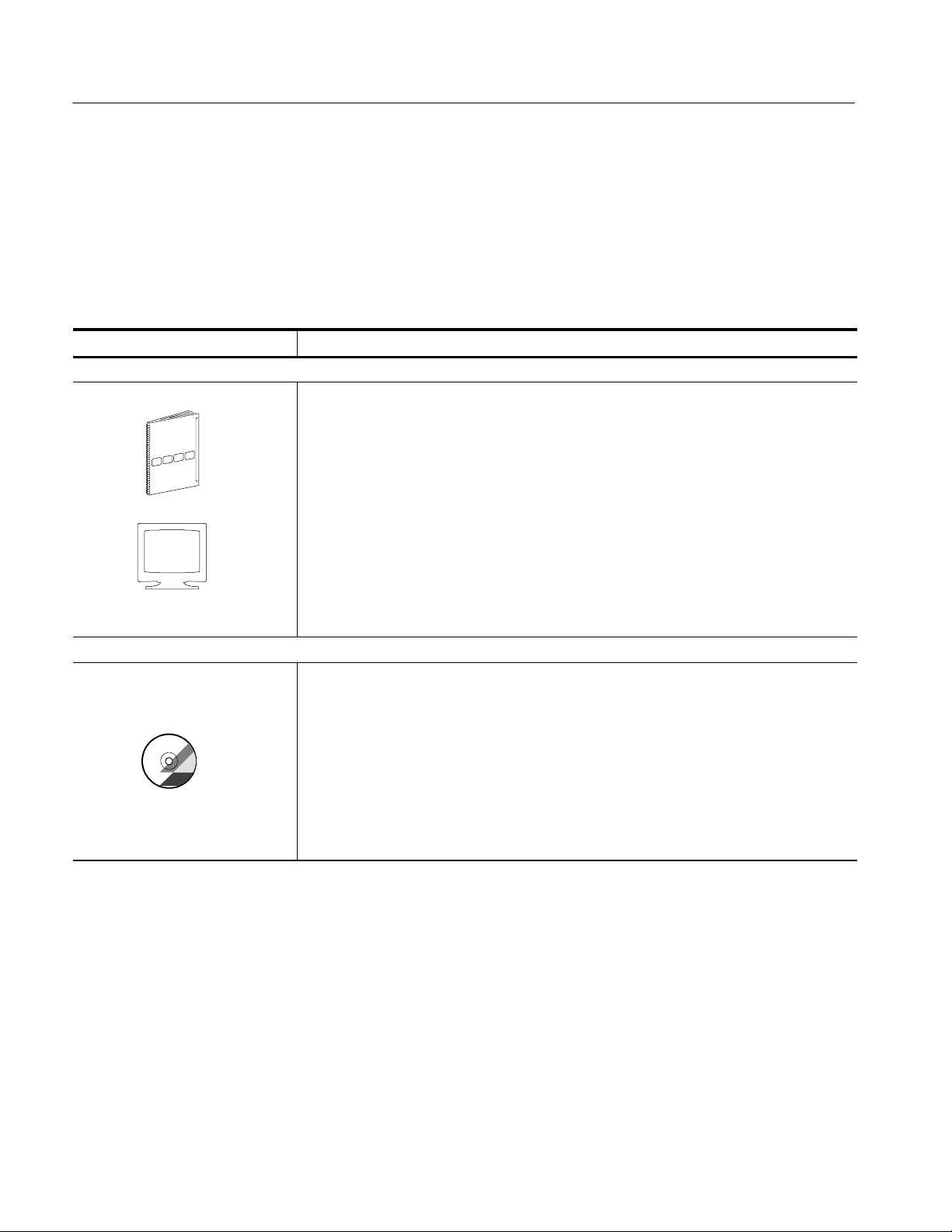
Table i: Tektronix Logic Analyzer Family documentation
Location TLA Documentation
Documents available in printed form and downloadable from the Tektronix web site.
Tektronix Logic Analyzer Family User Manual
TLA5000 Logic Analyzer Installation Reference
TLA5000 Series Logic Analyzer Installation Manual
P6417 & P6418 Logic Analyzer Probes Instructions
P6419 Logic Analyzer Probe Instructions
P6434 Mass Termination Probe Instructions
TLA6UP Field Upgrade Kit Instructions
tektronix.com
Documents available as PDF files on the documentation CD.
TLA7QS Quick Start Training Manual
TDS5000 Series & TLA5000 Series Rackmount Kit Instructions
Tektronix Logic Analyzer Family User Manual
TLA5000 Series Logic Analyzer Installation Manual
Tektronix Logic Analyzer Programmatic Interface (TPI.net)
Tektronix Logic Analyzer Programmatic Interface (TPI.com)
P6417 & P6418 Logic Analyzer Probes Instructions
P6419 Logic Analyzer Probe Instructions
P6434 Mass Termination Probe Instructions
xiv
TLA5000 Series Service Manual
Page 19

Contacting Tektronix
Preface
Phone 1-800-833-9200*
Address Tektronix, Inc.
Department or name (if known)
14200 SW Karl Braun Drive
P.O. Box 500
Beaverton, OR 97077
USA
Web site www.tektronix.com
Sales support 1-800-833-9200, select option 1*
Service support 1-800-833-9200, select option 2*
Technical support Email: support@tektronix.com
1-800-833-9200, select option 3*
6:00 a.m. -- 5:00 p.m. Pacific time
* This phone number is toll free in North America. After office hours, please leave a
voice mail message.
Outside North America, contact a Tektronix sales office or distributor; see the
Tektronix web site for a list of offices.
TLA5000 Series Service Manual
xv
Page 20

Preface
xvi
TLA5000 Series Service Manual
Page 21

Introduction
This manual contains information needed to properly service the logic analyzer.
This introduction contains information critical to safe and effective servicing.
To prevent personal injury or damage to the logic analyzer, consider the
following requirements before attempting service:
H Read the General Safety Summary and Service Safety Summary found at the
beginning of this manual.
H The procedures in this manual should only be performed by a qualified
service person.
H Read the Preface.
H Read the Operating Information chapter.
Be sure to follow all warnings, cautions and notes.
TLA5000 Series Service Manual
xvii
Page 22
Introduction
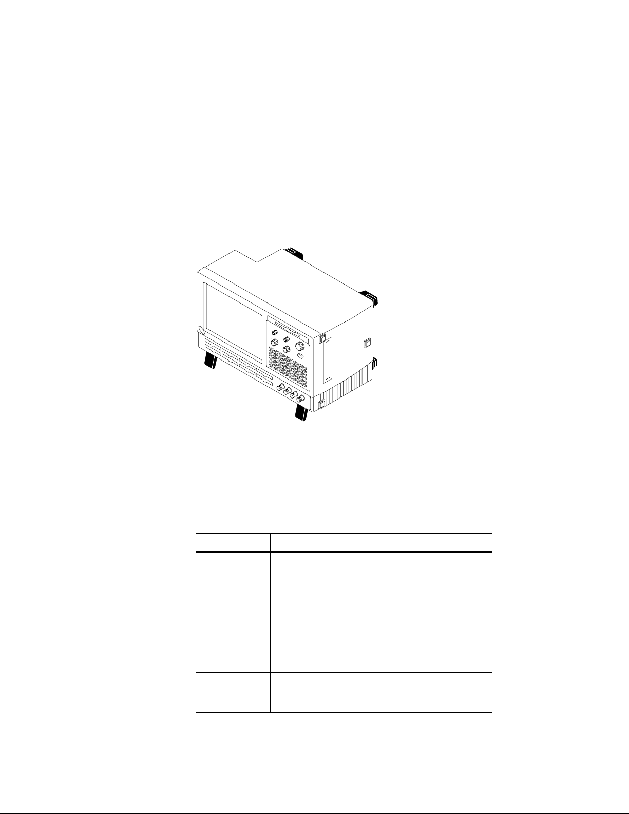
TLA5000 Series Logic Analyzers
The TLA5000 series logic analyzers consist of four portable logic analyzer
mainframes, which differ by channel width, and all of the accessories and
supports that are used with them. The logic analyzers are built upon the
Microsoft Windows operating system, which allows you to install any PC-compatible, third-party hardware and software on the instrument.
A TLA5000 logic analyzer is illustrated in Figure i.
Figure i: TLA5000 series logic analyzers
The TLA5000 series is comprised of four logic analyzers, as listed in Table ii.
Table ii: TLA5000 series family
Logic analzyer Description
TLA5201 34 channel, 2 GHz timing with 125 ps MagniVu
Acquisition, 235 MHz state, 512 K depth
Internal and external display
TLA5202 68 channel, 2 GHz timing with 125 ps MagniVu
Acquisition, 235 MHz state, 512 K depth
Internal and external display
TLA5203 102 channel, 2 GHz timing with 125 ps MagniVu
Acquisition, 235 MHz state, 512 K depth
Internal and external display
TLA5204 136 channel, 2 GHz timing with 125 ps MagniVu
Acquisition, 235 MHz state, 512 K depth
Internal and external display
xviii
TLA5000 Series Service Manual
Page 23

Adjustment and Certification Interval
Generally, you should perform the adjustments and certification (calibration)
described in the Performance Verification and Adjustment Procedures chapters
once per year, or following repairs that affect adjustment or calibration.
Strategy for Servicing
This manual supports and contains information needed for periodic maintenance
of the logic analyzer.
This manual supports and contains informaiton for corrective maintenance of this
product:
H Supports isolation of faults to the failed circuit board or assembly level
shown in the replaceable parts list of Chapter 10
H Supports removal and replacement of those boards or assemblies
Introduction
Service Offerings
Warranty Repair Service
H Supports removal and replacement of the fuse, knobs, chassis, and other
mechanical parts listed in the replaceable parts list
This manual does not support component-level fault isolation and replacement.
Tektronix provides service to cover repair under warranty as well as other
services that are designed to meet your specific service needs.
Whether providing warranty repair service or any of the other services listed
below, Tektronix service technicians are equipped to service the logic analyzer.
Services are provided at Tektronix Service Centers and on-site at your facility,
depending on your location.
Tektronix warrants this product for one year from date of purchase. The warranty
is located behind the title page in this manual. Tektronix technicians provide
warranty service at most Tektronix service locations worldwide. The Tektronix
product catalog lists all service locations worldwide, or you can visit us on our
Customer Services World Center web site at:
Tektronix.com/Measurement/Service
Calibration and Repair
Service
TLA5000 Series Service Manual
In addition to warranty repair, Tektronix Service offers calibration and other
services which provide solutions to your service needs and quality standards
compliance requirements.
xix
Page 24

Introduction
The following services can be tailored to fit your requirements for calibration
and/or repair of your logic analyzer.
Service Options. Tektronix Service Options can be selected at the time you
purchase your instrument. You select these options to provide the services that
best meet your service needs. These service options are listed on the Tektronix
Service Options page following the title page of this manual.
Service Agreements. If service options are not added to the instrument purchase,
then service agreements are available on an annual basis to provide calibration
services or post-warranty repair coverage. Service agreements may be customized to meet special turn-around time and/or on-site requirements.
Service on Demand. Tektronix offers calibration and repair services on a “per
incident” basis that is available with standard prices.
Self Service. Tektronix supports repair to the replaceable-part level by providing
for circuit board exchange.
Use this service to reduce down-time for repair by exchanging curcuit boards for
remanufactured ones. Tektronix ships updated and tested exchange boards. Each
board comes with a 90-day service warranty.
For More Information. Contact your local Tektronix service center or sales
engineer for more information on any of the Calibration and Repair Service just
described.
xx
TLA5000 Series Service Manual
Page 25

Specifications
Refer to the Tektronix Logic Analyzer Family Product Specifications document
for a complete list of specifications for the TLA5000 series logic analyzer
products. This document is available on the Tektronix Logic Analyzer Family
Product Documentation CD or can be downloaded from the Tektronix web site
as a PDF file.
TLA5000 Series Service Manual
1- 1
Page 26

Specifications
1- 2
TLA5000 Series Service Manual
Page 27
Operating Information
This chapter covers basic installation information and some high-level operating
instructions. For detailed installation information, refer to the TLA5000 Series
Installation Manual; for detailed operating information, refer to the online help.
Installation
The basic operating software is already installed on the hard disk. Use the
information in this section to set up the instrument for service or to verify proper
operation.
Before You Start
Environmental
Considerations
Chassis Ground
Connections
Verify that all parts and accessories for the logic analyzer are available.
The logic analyzer is designed to operate on a bench or a cart in the normal
position (on the bottom feet).
CAUTION. Allow a 5.1 cm (2 in) clearance at the bottom and sides of the
instrument to ensure proper cooling. Inadequate clearances can cause the
instrument to overheat and shut down.
Use the chassis ground connections to connect the grounds of the target system
(system-under-test) to the logic analyzer to ensure a common ground connection
between instruments.
Figure 2--1 shows the chassis ground connection on the logic analyzer.
TLA5000 Series Service Manual
2- 1
Page 28
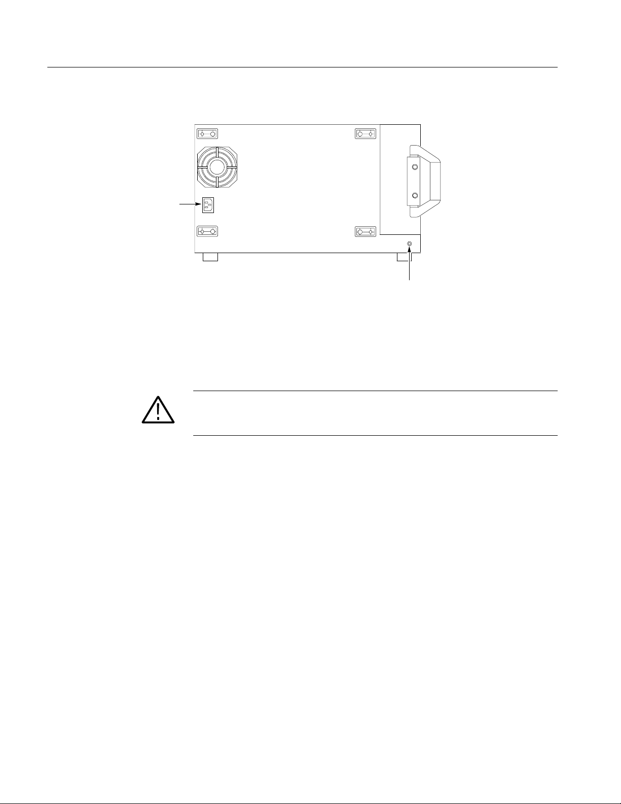
Operating Information
Rear panel
AC Power
Ground connection
Figure 2- 1: Location of the ground connection
Connect the Accessories
The accessory connections are the same as those on a personal computer. The
connection points are shown in Figure 2--2 on page 2--3.
WARNING. Before installing accessories to connectors (mouse, keyboard, etc.),
power off the logic analyzer. See Powering Off the Logic Analyzer on
page 2--5.
2- 2
TLA5000 Series Service Manual
Page 29
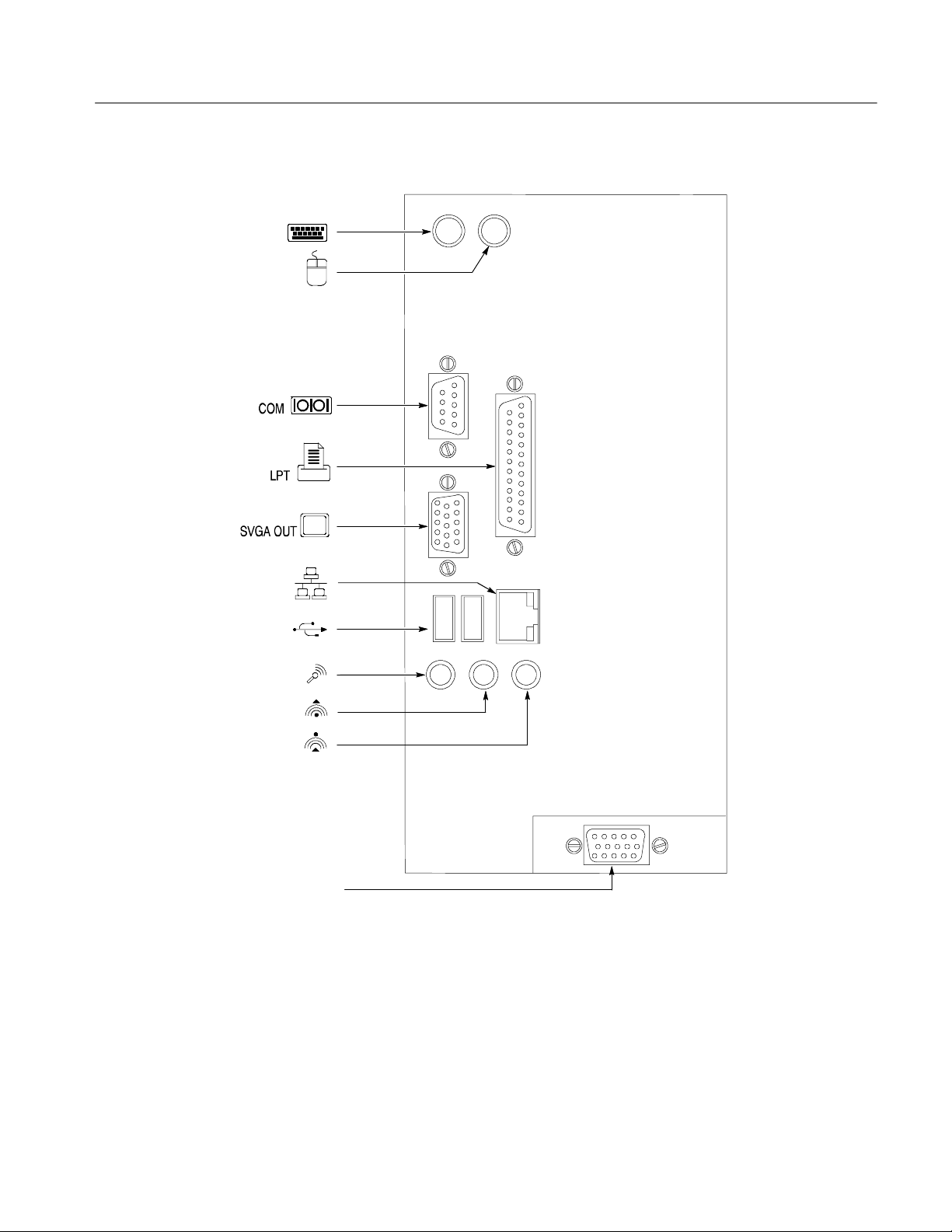
Description Icon/Label Locations
Keyboard ..............
Mouse..................
RS-232..........
Printer.............
Secondary video . .
Operating Information
Network................
USB..................
Audio MIC ............. ...
Audio line out...............
Audio line in ...............
SVGA OUTPrimaryvideo...........
Figure 2- 2: TLA5000 series accessory connections
TLA5000 Series Service Manual
2- 3
Page 30
Operating Information
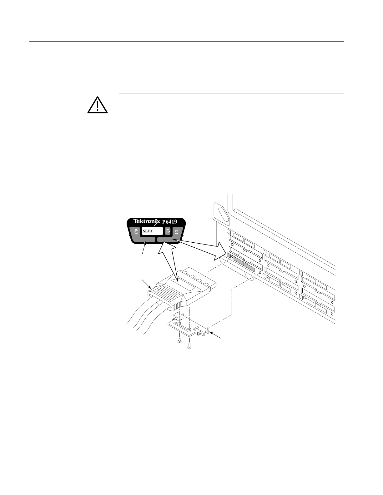
Connecting Probes
After you connect all the accessories, you can connect the probes to the
instrument.
CAUTION. When attaching the probe to the logic analyzer, you must use care to
evenly tighten probe screws until they are snug. First slightly tighten screws,
then snug each screw to 4 in-lbs (max). Undertightening the probe screws can
result in intermittent performance.
Connect the logic analyzer probes and the optional retaining brackets as shown
in Figure 2--3. Not all probes use the screws to connect the retaining bracket to
the probe; currently the P6418 and P6419 probes use the screws, while the
P6417 and P6434 probes do not need the screws to hold the retaining bracket in
place.
Match color-coded
labels
P6419
Attach optional probe
retainer brackets
Figure 2- 3: Connecting the logic analyzer probes to the logic analyzer
2- 4
TLA5000 Series Service Manual
Page 31

Operating Information
Power On the Logic
Analyzer
On/Standby
Switch
Follow these steps to power on the instrument.
CAUTION. To prevent damage to the accessories, connect the keyboard, mouse,
and other accessories before applying power to the product.
1. Connect the power cord (see Figure 2--4 for the AC power location).
2. If you have an external monitor, connect the power cord and video cable to
the logic analyzer and then power on the monitor.
3. Press the On/Standby switch to power on the instrument (see Figure 2--4 for
the switch location).
4. Wait for the self test to complete and the application to start.
AC Power
Powering Off the Logic
Analyzer
Rear panel
Figure 2- 4: On/Standby and AC Power switch locations
The logic analyzer has a built-in soft power-off function that safely powers off
the logic analyzer when you press the On/Standby switch.
To completely remove power to the instrument, press the On/Standby switch,
and then remove the power cord from the rear panel. You can also shut down the
instrument through the Windows Start Menu.
TLA5000 Series Service Manual
2- 5
Page 32

Operating Information
Performing the Incoming
Inspection
Checking the P64xx Logic
Analyzer Probes
(Optional)
After the power-on diagnostic finishes checking the basic functionality of the
logic analyzer, you need to perform an incoming inspection. The incoming
inspection consists of verifying the basic operation of the logic analyzer.
For a more detailed functionality check, run the following self-calibration and
extended diagnostics procedures.
NOTE. Allow the mainframe to warm up for 30 minutes before running the
self-calibration.
To run self-calibration and diagnostics, perform the following:
1. Disconnect any probes that are attached to the input connectors.
2. Select the System menu and click Calibration and Diagnostics.
3. Run the self-calibration and then the extended diagnostics by selecting the
proper tab. Results of the tests display on the individual property page.
Connect the P64xx logic analyzer probes to a signal source, start an acquisition,
and verify that the acquired data is displayed in either the listing or waveform
windows. You can also use the Activity Indicators in the logic analyzer Setup
window to view signal activity at the probe tips.
Software Installation
NOTE. If you connect probes to any channels other than the A2 and A3 groups,
you must define the groups and channels in the Setup window and set the
threshold voltages before acquiring data on other probe channels.
The logic analyzer ships with the product software installed, so only perform
these procedures if reinstallation becomes necessary.
The Windows operating system and drivers are factory installed on the logic
analyzer hard disk. The hard disk Image CDs serve as a backup in the event that
you have to restore the hard disk drive.
2- 6
TLA5000 Series Service Manual
Page 33

Operating Information
Operating Information
All features of the logic analyzer can be accessed through the menus using a
mouse. Refer to the online help for specific operating information.
Figure 2--5 shows the controls, connectors and floppy disk drive location.
Floppy
disk drive
On/Standby
switch
Probe Connectors
Figure 2- 5: Controls and connectors on the front panel
The multi-function knob is used primarily for incrementing and decrementing
values in selected menu boxes. The four positioning and scale knobs provide
scrolling of the logic analyzer displays.
NOTE. For external connectors on the rear panel see Figure 2--2 on page 2--3.
Connecting Probes to the Target System
The logic analyzer connects to the target system through probes. Several
different probes are available for the logic analyzer. For probe-specific connection details, refer to the appropriate probe instruction manual or browse the
Tektronix Web site.
Additional Information
For detailed information on using the logic analyzer refer to the online help. For
additional information on the latest software version or other information, refer
to the release notes. To access the release notes, click Start > Programs >
Tektronix Logic Analyzer > TLA Release Notes.
TLA5000 Series Service Manual
2- 7
Page 34

Operating Information
2- 8
TLA5000 Series Service Manual
Page 35

Theory of Operation
This chapter provides a high-level overview of the board level theory of
operation for the logic analyzer. Refer to the Diagrams chapter for a functional
block diagram of the instrument.
Hardware
General
Mother Board
The logic analyzer controller contains a PC motherboard and microprocessor
system that controls the entire instrument. The instrument features a flat-panel
display, front panel keyboard with control knobs, probe interface, and external
connections for a keyboard, mouse, and other PC accessories.
The Intel Micro ATX mother board provides all the benefits of a high-performance PC-based mother board. The mother board contains the microcontroller,
memory, battery, and input-output components typically used with a PC.
The following peripheral interfaces are included:
H One parallel port
H Four USB 2.0 ports (two external, two internal)
H Two serial ports (one internal, one external)
H Two IDE interfaces supporting up to ATA-100
H Floppy disk drive interface
H PS/2 keyboard and mouse ports
H 10/100 Mbit/s LAN port
Interface Board
TLA5000 Series Service Manual
H Secondary display connector
The Interface board connects the mother board to the rest of the instrument
through the PCI connector. The interface board contains the following circuitry:
H LPU Circuitry. The LPU circuitry controls the acquisition system using a
68360 microprocessor.
H Internal Display. The interface board contains the display controller that
drives the 1024 X 768 resolution as well as an external display connector.
The display signal at the external primary connector is identical to the
3- 1
Page 36

Theory of Operation
internal LCD display signal when used with the Windows 2000 Proffessional
operating system.
H Power Distribution and Miscellaneous Circuitry. The power supply circuitry
on the interface board generates the majority of the 2.5 V needed by the
acquisition circuitry. The interface board also provides the interface between
the front panel keypad and knobs, the On/Standby switch, main power
supply, and the mother board.
Power Supply
Fans
Front Panel Keypad and
Knobs
Display
The power supply is a switching power converter with active power factor
correction. It supplies power to all of the circuitry in the logic analyzer. The
power is distributed to the PC interface board and to the hard disk drive
connectors.
The fan assembly provided forced air cooling for the logic analyzer and are
controlled by the microprocessor.
The front panel keypad consists of a full QWERTY keypad. The keypad
connects to the mother board through one of the internal US B connections. The
front panel keypad is active simultaneously with an optional external keyboard.
Five front panel knobs provide the following manual controls:
H Two horizontal and vertical sizing knobs
H Two horizontal and vertical position knobs
H One multifunction knob
The internal display is a 10.4-inch diagonal Active Matrix Thin-Film-Transistor
(TFT) liquid crystal display (LCD) with a built-in back light. The color LCD is
supported by an external DC switching regulator board to provide the back-light
voltage and a display adapter board which supports connector interfacing from
the the PC interface board and to the On/Standby front panel switch.
3- 2
Hard Disk Drive
Floppy Disk Drive
The internal hard disk drive is a standard 3.5-inch IDE drive which interfaces
directly to the mother board through a standard UDMA 80 conductor cable. The
hard disk drive is not removeable. The C D drive uses the slot on the secondary
IDE interface.
The floppy disk drive is a standard 1/2-inch drive supporting 3.5-inch 1.44
MByte high-density double sided floppy disks. The drive is an internal USB
floppy disk drive.
TLA5000 Series Service Manual
Page 37

Theory of Operation
CD Drive
USB 2.0 Ports
Software
Probe Interface
The CD drive is a slim-line CD-RW drive. The actual CD-RW drives may vary
as new drives become available.
A dual external USB 2.0 port allows external connection to USB devices. Two
ports are use internally by the keypad and the floppy disk drive.
The instrument operation is controlled by the TLA Application Software built
upon the Windows Operating System.
The logic analyzer connects to the target system through the probe interface. The
logic analyzer can use the following probes to acquire data from the target
system:
H P6417
H P6418
Acquisition
H P6419
H P6434
Depending on the instrument configuration, you can connect up to eight P6417,
P6418, and P6419 general purpose probes or up to four P6434 high-density
probes.
The acquisition board is mounted on the bottom of the instrument. The number
of channels for each logic analyzer depend on the configuration. The acquisition
board takes the data from the probes, determines when to clock the data into
memory, and communicates the acquisition information with the rest of the
instrument.
Depending on the instrument configuration the logic analyzer has zero, one, or
two daughter boards that provide for additional probe connections.
No manual adjustments or calibration exist. All calibration is done by software
but requires the TLACAL1 fixture for the adjustment procedures. The adjustment procedures are described in the Adjustment Procedures chapter of this
manual.
TLA5000 Series Service Manual
3- 3
Page 38

Theory of Operation
Internal Indicator LEDs
The logic analyzer has two internal indicator LEDs located on the PC Interface
board. These LEDs can be used for troubleshooting:
H Ready Indicator. This LED indicates that the instrument has passed the
power-up diagnostics and is ready to communicate with the acquisition
controller.
H Access Indicator. This LED turns on any time the acquisition controller
accesses the main instrument circuitry.
3- 4
TLA5000 Series Service Manual
Page 39

Performance Verification
This chapter contains procedures for functional verification, certification, and
performance verification for the logic analyzer. Generally, you should perform
these procedures once per year or following repairs that affect certification.
NOTE. This chapter does not contain any procedures for verifying, adjusting, or
certifying the TLACAL1 Performance Verification fixture. If the test fixture
requires, verification, adjustment, or certification, you must return the test
fixture to the factory.; contact your local Tektr onix service center for more
information.
Summary V erification
Functional verification procedures verify the basic functionality of the instrument inputs, outputs, and basic instrument actions. These procedures include
power-on diagnostics, extended diagnostics, and manual check procedures.
These procedures can be used for incoming inspection purposes.
Certification procedures certify the accuracy of an instrument and provide a
traceability path to national standards. Calibration data reports are produced for
the logic analyzers as output from the performance verification and adjustment
software.
Performance verification procedures confirm that a product meets or exceeds the
performance requirements for the published specifications. Refer to Figure 4--1
on page 4--2 for a graphic overview of the procedures.
Adjustment procedures check for, and if necessary, correct any adjustment errors
discovered when performing functional or performance verification procedures.
The adjustment procedures for the logic analyzers are controlled by software but
some of the adjustment procedures require manual intervention to move probes
or to change test equipment settings.
The performance verification and adjustment software is provided on the product
CD-ROM.
TLA5000 Series Service Manual
4- 1
Page 40

Performance Verification
Determine equipment
to certify.
Use
Tektronix-supplied
probes.
Go to appropriate
procedure(s).
Gather required test
equipment.
Is it OK
No
with customer to
remove/reconnect probes
from System
Under Test?
Select procedure.
Configure customer’s logic
analyzer as described in
procedure.
Set up test equipment.
Yes
Allow the logic analyzer and test
equipment to warm up (30 minutes).
Load PV/Adjust
software.
Perform procedure
using software.
Do tests
pass?
No
Yes
Create necessary
calibration certificate
from data stored in
certification file.
No
Are
all certifications
complete?
Repair or adjust
equipment as
required.
Figure 4- 1: Calibration/certification procedure flow chart
4- 2
Yes
Done
TLA5000 Series Service Manual
Page 41

Test Equipment
The procedures use external, traceable signal sources to directly test characteristics that are designated as checked (n) under the TLA5000 Series Logic
Analyzer specifications. These specifications are listed in the Tektronix Logic
Analyzer Product Specifications document on the Tektronix Logic Analyzer
Family Product Documentation CD or can be downloaded from the Tektronix
website as a PDF file.
Table 4--1 shows the required equipment list; this equipment is required for the
performance verification and adjustment procedures.
Table 4- 1: Test equipment
Item number and description Minimum requirements Example
Performance Verification
1. TLA5000 Logic Analyzer TLA5000 Series Logic Analyzer with TLA
Application software V4.3 or higher
2. Logic analyzer probes P6417, P6418, or P6419 logic analyzer
probes. One probe required for every
17-channels
3. Performance Verification test
fixture with accessories
4. Digital Multimeter with probes Agilent 34401A, 6.5 digit display, 35 ppm, 1
5. USB-GPIB controller: National Instruments 778195-01
6. RS-232 cable 2 m RS-232 cable, 9-pin female-to-female
1
The P6419 logic analyzer probes can be used to complete all of the verification procedures. The P6417 and the P6418
logic analyzer probes can be use to complete all of the verification procedures except the Setup and Hold procedures.
TLACAL1 test fixture No substitute allowed
year accuracy, 1000 readings per minute,
100 nV sensitivity, GPIB controllable
Windows 2000 compatible with 2 m cable
connector
1
TLA5204 Logic Analyzer
No substitute allowed
No substitute allowed
Tektronix iView cable
Tektronix part number 012-1379-00
Test Equipment Setup
The TLACAL1 Performance Verification and Adjustment test fixture and the
performance verification software are required to perform the performance
verification procedures, certification procedures, and adjustment procedures.
TLA5000 Series Service Manual
4- 3
Page 42

Performance Verification
Connecting the Test
Fixture
You will need to connect the test fixture to the logic analyzer and associated test
equipment before running any of the procedures. A complete list of test
equipment is listed in Table 4--1. Complete the following steps to connect the
test equipment to the logic analyzer:
1. Connect the RS-232 cable from the COM A connector of the logic analyzer
to the RS-232 connector on the test fixture.
NOTE. When using GPIB, make sure that you select unique GPIB addresses on
the individual instruments to avoid conflicts.
2. Connect the iView cable from the USB connector on the logic analyzer to the
GPIB connector on the DMM.
3. Connect the multimeter leads to the DMM test points on the test fixture.
4. Connect the power cord to the test fixture.
NOTE. The performance verification software will prompt you to make necessary
probe connections when you run the individual tests.
Installing the Performance
Verification and
Adjustment Software
The performance verification software is a separate application that consists of
executable software files. The software must be installed on the hard disk before
you can use it. You must quit the logic analyzer application before starting the
performance verification software; you cannot run both applications at the same
time.
NOTE. If your logic analyzer already has the performance verification software
installed, verify that the performance verification software version matches that
of the logic analyzer application software. If the software versions do not match,
you must delete the performance analysis software from the hard disk drive and
install the matching version.
Complete the following steps to install the performance verification software:
1. Close all open applications.
2. Insert Disc 1 of the Tektronix Logic Analyzer Family application software
CD in the CD-ROM drive.
3. On the desktop select Start → Run to display the Run dialog.
4- 4
TLA5000 Series Service Manual
Page 43

Performance Verification
4. In the Run dialog box, enter the following path or use the Browse button to
navigate to the path:
D:\TLACAL\Setup.exe
5. Click OK to begin the installation program and then follow the on-screen
instructions to install the software.
6. Remove the CD when the installation is complete.
To remove the software from the logic analyzer, use the Add/Remove Program
utility from the Windows Control Panel.
Starting the Performance
Verification Software
Use the following steps to start and run the software. These steps are repeated
under the individual procedures but are listed here to give you an overview of
using the software.
1. Allow the logic analyzer and all test equipment to warm up for at least 30
minutes.
2. Exit the logic analyzer application.
3. Select Start → Programs → Tektronix Logic Analyzer → TLACAL. An
application window similar to Figure 4--2 appears.
4. The instrument appears selected in the list. Click either the Verification
button, Adjustment button, or Certification button depending on the type of
procedure that you want to perform.
TLA5000 Series Service Manual
Figure 4- 2: Performance verification soft ware startup window
4- 5
Page 44

Performance Verification
Software Overview
Obtaining Test Results
After selecting the type of test that you want to run, a new dialog box appears.
The dialog box contains the following information:
H Name and serial number of the instrument to be tested
H Probe selection box
H A list of procedures organized by groups
The individual procedures are organized by groups that require the same test
equipment setups. Depending on the type of probe selected, the related procedures are indicated by a checkmark adjacent to the procedure. You can disable
any procedures by clearing the check box. All selected procedures will be tested
beginning with the top-most procedure in the dialog box. In most cases, you will
want to run all of the selected tests.
The software determines which GPIB instruments are required to perform the
selected procedures and sets up the individual instruments. If any equipment
problems are found, an appropriate error message will be displayed.
After completing the various procedures, you have the option of saving the test
results to a text file on the hard disk. You can assign a name to the file from a
dialog box. You can then edit the file as necessary using any of the Windows
tools or print the file.
Troubleshooting
If any tests fail, use the following steps to troubleshoot the problems:
1. Check that all test equipment is powered on and has the proper warm-up
time.
2. Check all test equipment for improper or loose connections.
3. Verify that the probes are properly connected to the logic analyzer.
4. Verify that all probes are properly connected to the test fixture and to the
correct locations on the test fixture.
5. Rerun the instrument diagnostics.
6. Run the self calibration from the TLA application.
7. Run the adjustment procedures.
8. Run the tests a second time to verify the failure.
9. If all else fails, contact your local Tektronix service center for additional
information.
4- 6
TLA5000 Series Service Manual
Page 45

Functional Verification
Performance Verification
This section contains instructions for performing the functional verification
procedures for the logic analyzer. These procedures provide an easy way to check
the basic functionality of the logic analyzer and probes. The test fixture or
software is not required for any of the functional verification checks.
If any check within this section fails, refer to the Troubleshooting section in the
Maintenance chapter of this manual for assistance. Failed tests indicate the
instrument needs to be serviced.
The functional verification procedure consists of the following parts:
H Self tests and power-on diagnostics
H Extended diagnostics
H Mainframe diagnostics
H Probe functional verification
Test Equipment
Setup
Self Tests and Power-On
Diagnostics
This procedure provides a functional check only. If more detailed testing is
required, perform the Performance Verification Procedures beginning on
page 4--11 after completing this procedure.
Perform these tests whenever you need to gain confidence that the instrument is
operating properly.
You will need the following equipment to complete the functional verification
procedure:
H TLA5000 series logic analyzer
H At least one logic analyzer probe
H One short BNC-to-BNC cable (to complete the Mainframe Diagnostics)
Power on the logic analyzer and allow a 30-minute warm-up period before
continuing with any procedures in this section.
During power-on, the instrument performs an internal self test to verify basic
functionality. No external test equipment is required.
TLA5000 Series Service Manual
Next, the power-on diagnostics are run. If any self tests or power-on diagnostics
fail, the instrument displays the Calibration and Diagnostics property sheet
showing the failed test.
4- 7
Page 46

Performance Verification
NOTE. If any diagnostics fail, you may need to run the self calibration before
attempting to service the logic analyzer. The Self Calibration procedure is listed
under Self Calibration beginning on page 5--3.
Extended Diagnostics
The following procedure checks the basic functionality of the logic analyzer by
running the extended diagnostics.
NOTE. Running the extended diagnostics invalidates any acquired data. If you
want to save any of the acquired data, do so before running the extended
diagnostics.
Perform the following steps to complete the functional verification procedures:
1. Disconnect any probes connected to the logic analyzer.
2. In the logic analyzer application, go to the System menu and select
Calibration and Diagnostics.
3. Click the Extended Diagnostics tab.
4. Select the top level test and click the Run button.
The diagnostics will perform each of the tests listed in the menu under the
module selection. All tests that displayed an Unknown status will change to
a Pass or Fail status depending on the outcome of the tests.
5. Scroll through the test results and verify all tests pass.
Mainframe Diagnostics
4- 8
NOTE. If the extended diagnostics fail, run the self calibration procedures as
described under Self Calibration beginning on page 5--3 and then rerun the
extended diagnostics.
The Mainframe Diagnostics are comprehensive software tests that check the
logic analyzer. Perform the following steps to run the mainframe diagnostics:
1. Quit all other applications on the instrument.
2. Select Start → Programs → Tektronix Logic Analyzer → TLA Mainframe
Diagnostics.
3. Click the Run button to start the diagnostics. Follow the online instructions
to complete the tests. If necessary, refer to the online help for more information on the diagnostics.
TLA5000 Series Service Manual
Page 47

Performance Verification
Probe Functional
Verification
There are two ways of verifying probe functionality. One way is to connect the
probes from the logic analyzer to a signal source, adjust the appropriate threshold
voltage levels, and then verify that the logic analyzer acquires the data in a
listing or waveform window.
Alternately, you can perform the performance verification procedures which will
verify that the logic analyzer and the attached probes meet or exceed the
advertised specifications. The performance verification procedures are covered in
the remainder of this chapter.
Performance Verification Instructions
This section contains information to verify the performance of the logic analyzer.
Testing is performed using the performance verification software and the test
fixture.
As a general rule, these tests should be done once a year.
Prerequisites
The performance verification procedures in this section comprise an extensive,
valid confirmation of performance and functionality when the following
requirements are met:
Procedure Overview
H The performance verification software must be loaded on the hard disk.
H The logic analyzer, test fixture, and other related test equipment must be
installed, connected, and operating for at least 30 minutes at an ambient
temperature between +20 _C and +30 _C.
H The logic analyzer and the test fixture must have been last adjusted at an
ambient temperature between +20 _C and +30 _C.
H The logic analyzer and test fixture must be in an operating environment
within the limits described in the Tektronix Logic Analyzer Product
Specifications document.
When using the performance verification software, you will connect external test
equipment and probes to the logic analyzer in response to prompts on the screen.
The software automatically selects the instrument settings and determines the
results of each test.
The results of the tests are recorded in a temporary file and are available upon
test completion for completing test records.
TLA5000 Series Service Manual
4- 9
Page 48

Performance Verification
NOTE. Before testing an instrument following repair, you must first complete the
adjustment procedure.
Table 4--2 lists the specifications as checked (n)intheTektronix Logic Analyzer
Product Specifications document for the logic analyzer and the performance
verification software checks used to verify those specifications. In addition to the
software test listed in the table, some specifications are verified by the built-in
diagnostics. By running all tests and diagnostics, you will verify the performance
of the logic analyzer and probes.
Table 4- 2: Performance verification tests
Specification Test method
Threshold accuracy Verified by the Thresholds test. Certified by
running Certification procedure; refer to Logic
Analyzer Certification beginning on page 4--19.
Channel-to-channel skew Verified indirectly by the Setup and Hold
procedure
Internal sampling period Verified indirectly by Pulse Width procedure
and Time Base Accuracy procedure
Minimum recognizable word (across all
channels)
Setup and hold window size (data and
qualifiers)
Maximum synchronous clock rate Diagnostics verify the clock detection/sampling
Counters and timers Verified by diagnostics
Trigger state sequence rate Verified indirectly by the at-speed diagnostics
Verified indirectly by the Setup and Hold
procedure and by the Internal Sampling Period
Verified directly by Setup and Hold procedure
(Can only be run with P6419 probes)
circuitry. Bandwidth is verified by Setup and
Hold procedures and by the Pulse Width
procedure
and the Internal Sampling Period
4- 10
TLA5000 Series Service Manual
Page 49

Performance Verification Procedures
analy
Table 4--3 provides a summary of the performance verification procedures. The
procedures are listed by groups and include individual procedures. Some of these
procedures are optional and are recommended for performing a thorough
performance verification. Others are the minimum required to verify the
advertised specifications of the logic analyzer. Each group requires different
equipment setups.
Table 4- 3: TLA5000 performance verification procedures
Procedure by groups Notes
Module+Probe Gain and Offset Procedures
Threshold
Module+Probe Timing Procedures
Pulse Width
Timebase
1
2
Performance Verification
Setup and Hold Procedure Can only be verified with P419 logic
Setup and Hold
1
Certifiable parameter. This procedure can be run separate from the performance
verification procedures. Select the Certification button from m ain wi ndow in the
software. The Certification instructions are listed on page 4- 19.
2
The Timebase procedure indirectly tests the CLK10 specification.
zer probes
Use the tables and illustrations to set up and execute the procedures. The
procedures assume that you have already installed the performance verification
software on the logic analyzer. They also assume that you will only perform the
procedures selected in each group.
Figure 4--3 shows the locations of connectors and test points on the test fixture.
You may need to refer to this illustration when connecting probes to the test
fixture. You should also refer to the label on top of the test fixture.
TLA5000 Series Service Manual
4- 11
Page 50

Performance Verification
4- 12
Figure 4- 3: TLACAL1 test fixture connections
TLA5000 Series Service Manual
Page 51

Performance Verification
Module+Probe Gain &
Offset Procedures
These procedures verify the threshold accuracy of the instrument. These tests can
be run separately as certifiable parameters (see Logic Analyzer Certification
beginning on page 4--19.
Complete the following steps to run the procedures:
1. If you haven’t already done so, power on the instrument and allow all test
equipment to warm up for 30 minutes.
2. Exit the TLA application.
3. Double-click the TLACAL icon on the desktop. An application window
similar to Figure 4--2 on page 4--5 appears.
4. Click the Verification button to start the software. A Verification dialog box
similar to Figure 4--4 appears.
TLA5000 Series Service Manual
Figure 4- 4: Default Verification dialog box
5. Select the probe type near the bottom of the dialog box.
4- 13
Page 52

Performance Verification
6. Verify that Pulse Threshold is selected under Module+Probe Gain & Offset
Procedures. Clear all other procedure selections in the dialog box.
NOTE. The software will perform all selected procedures without interruption,
with the exception of when user interaction is required (such as moving a probe).
To limit the test to specific procedures, clear any procedures that you do not
want to run. If you want to run all of the selected procedures, you need to pay
close attention to the connection instructions as they are displayed on the screen.
7. Click the Next button at the bottom of the dialog box to display the probe
connection instructions. Follow the on-screen instructions to connect the
probes from the logic analyzer to the test fixture. If necessary, refer to the
test fixture label to determine the correct probe connection.
NOTE. When connecting the P6419 Logic Analyzer probes, make sure that the
alignment pin on the probe head aligns with the hole on the test fixture. Tighten
the probe head screws by alternating between them until they are finger tight (no
more than 1 in-lbs of torque).
8. Click the Next button to begin the verification procedure.
The software will begin the procedures and display a list of results in the
window.
9. After the first set of procedures are done, click the Next button to display the
instructions for the next step. In most cases you only need to connect a
different probe to the test fixture.
10. After changing the connections, click the Next button to continue the tests.
11. Repeat steps 7 through 8 as indicated by the software.
12. After the procedure finishes, click the Next button to open the Finish dialog
box where you can save the results to a file. Enter a file name and click the
Save button. You can use the Save dialog to save the file to a folder of your
choice or use the default location.
13. Click the Finish button to complete the process.
4- 14
TLA5000 Series Service Manual
Page 53

Performance Verification
Module+Probe Timing
Procedures
These procedure verify the minimum pulse width specification and the accuracy
of the time base.
It is assumed that the logic analyzer is already connected to the test fixture and
that all test equipment has had a 30-minute warm-up period. Complete the
following steps to run the procedures:
1. If the TLA application is running, exit the application.
2. Double-click the TLACAL icon on the desktop. An application window
similar to Figure 4--2 on page 4--5 appears.
3. Click the Verification button to start the software.
4. Select the probe type near the bottom of the dialog box.
5. Verify that Pulse Width and Timebase are selected under Module+Probe
Timing Procedures. Clear all other procedures in the dialog box.
NOTE. The software will perform all selected procedures without interruption,
with the exception of when user interaction is required (such as moving a probe).
To limit the test to specific procedures, clear any procedures that you do not
want to run. If you want to run all of the selected procedures, you need to pay
close attention to the connection instructions as they are displayed on the screen.
6. Click the Next button at the bottom of the dialog box to display the probe
connection instructions. Follow the on-screen instructions to connect the
probes from the logic analyzer to the test fixture. If necessary, refer
Figure 4--5 on page 4--16 and to the test fixture label to determine the correct
probe connection.
NOTE. When connecting the P6419 Logic Analyzer probes, make sure that the
alignment pin on the probe head aligns with the hole on the test fixture. Tighten
the probe head screws by alternating between them until they are finger tight (no
more than 1 in-lbs of torque).
TLA5000 Series Service Manual
4- 15
Page 54

Performance Verification
4- 16
Figure 4- 5: Module+Probe timing procedure probe connections
7. Click the Next button at the bottom of the dialog box to begin the procedure.
The software will begin the procedures and display a list of results in the
window.
TLA5000 Series Service Manual
Page 55

Performance Verification
NOTE. Note that the Timebase test is only run on the first probe section. When
the software tests the next section, the Timebase test is not run. The screen will
display a line indicating that the test is not run; you can ignore this message.
8. After the first set of procedures are done, click the Next button to display the
instructions for the next step. In most cases you only need to move a probe
or connect a different probe to the test fixture.
9. After changing the connections, click the Next button to continue the
procedures.
10. Repeat steps 7 through 8 as indicated by the software.
11. After the procedure finishes, click the Next button to open the Finish dialog
box where you can save the results to a file. Enter a file name and click the
Save button. You can use the Save dialog box to save the file to a folder of
your choice or use the default location.
12. Click the Finish button to complete the process.
Setup and Hold Procedure
This procedure verifies the setup and hold specification of the logic analyzer.
This procedure can be verified using P6419 probes only. Depending on the
number of channels in your instrument, the procedure requires several iterations
of connecting and disconnecting probes to the test fixture.
Complete the following steps to start the software and to run the procedures:
1. If the TLA application is running, exit the application.
2. Double-click the TLACAL icon on the desktop. An application window
similar to Figure 4--2 on page 4--5 appears.
3. Click the Verification button to start the software.
4. Verify that Setup and Hold is selected under Setup and Hold Procedures.
NOTE. The software will perform all selected procedures without interruption,
with the exception of when user interaction is required (such as moving a probe).
To limit the test to specific procedures, clear any procedures that you do not
want to run. If you want to run all of the selected procedures, you need to pay
close attention to the connection instructions as they are displayed on the screen.
5. Clear all other procedures in the dialog box.
TLA5000 Series Service Manual
4- 17
Page 56

Performance Verification
6. Click the Next button at the bottom of the dialog box to display the probe
connection instructions. Follow the on-screen instructions to connect the
probes from the logic analyzer to the test fixture. If necessary, refer
Figure 4--6 on page 4--6 and to the test fixture label to determine the correct
probe connection.
NOTE. When connecting the P6419 Logic Analyzer probes, make sure that the
alignment pin on the probe head aligns with the hole on the test fixture. Tighten
the probe head screws by alternating between them until they are finger tight (no
more than 1 in-lbs of torque).
4- 18
Figure 4- 6: P6419 Setup & Hold procedure connections
7. Click the Next button at the bottom of the dialog box to begin the procedure.
TLA5000 Series Service Manual
Page 57

Performance Verification
The software will begin the procedures and display a list of results in the
window.
8. After the first set of procedures are done, click the Next button to display the
instructions for the next step. Move the probes on the test fixture as indicated
by the instructions.
9. After changing the connections, click the Next button to continue the
procedures.
10. Repeat steps 7 through 8 as indicated by the software.
11. After the procedure finishes, click the Next button to open the Finish dialog
box where you can save the results to a file. Enter a file name and click the
Save button. You can use the Save dialog to save the file to a folder of your
choice or use the default location.
12. Click the Finish button to complete the process.
Logic Analyzer Certification
This section describes the procedures to certify the logic analyzer. Y ou can
certify the logic analyzer without completing the main performance verification
procedures. Table 4--4 lists the certifiable parameters for the logic analyzer.
Table 4- 4: Logic analyzer certification test
Performance verification test name Specification tested
1. Thresholds
1
Certifiable parameter
To certify the logic analyzer, use the performance verification software and click
the Certification button. Perform the required procedure and then print the results
to obtain a copy of the software-generated calibration data report.
NOTE. The certification procedures have the same prerequisites as the performance verification procedures. Refer to Prerequisites on page 4--9 for a
detailed list of prerequisites.
1
Threshold accuracy
Equipment Setups
TLA5000 Series Service Manual
These procedures require the same setups as described for the Performance
Verification procedures. It is assumed that the logic analyzer is already connected
to the test fixture and that the performance verification software is installed on
the logic analyzer.
4- 19
Page 58

Performance Verification
Power on the test fixture, logic analyzer, and other test equipment. Allow all test
equipment to warm up for 30 minutes before continuing.
Start the Software
Complete the following steps to run the procedures:
1. If you have not already done so, exit the TLA application.
2. Double-click the TLACAL icon on the desktop. An application window
similar to Figure 4--2 on page 4--5 appears.
3. Click the Certification button to start the software. A Certification dialog
box similar to Figure 4--7 on page 4-- 20 appears.
4- 20
Figure 4- 7: Default Certification procedure dialog box
4. Select the probe type near the bottom of the dialog box.
The Threshold Certification Procedure is selected by default.
5. Click the Next button at the bottom of the dialog box to display the probe
connection instructions. Follow the on-screen instructions to connect the
TLA5000 Series Service Manual
Page 59

Performance Verification
probes from the logic analyzer to the test fixture. If necessary, refer to the
test fixture label to determine the correct probe connection.
NOTE. When connecting the P6419 Logic Analyzer probes, make sure that the
alignment pin on the probe head aligns with the hole on the test fixture. Tighten
the probe head screws by alternating between them until they are finger tight (no
more than 1 in-lbs of torque).
6. Click the Next button to begin the certification procedure.
The software will begin the procedures and display a list of results in the
window.
7. After the first set of procedures are done, click the Next button to display the
instructions for the next step. In most cases you only need to move a probe
or connect a different probe to the test fixture.
8. After changing the connections, click the Next button to continue the tests.
9. Repeat steps 7 through 8 as indicated by the software.
10. After the procedure finishes, click the Next button to open the Finish dialog
box where you can save the results to a file. Enter a file name and click the
Save button. You can use the Save dialog to save the file to a folder of your
choice or use the default location.
11. Click the Finish button to complete the process.
12. Locate the file that you saved in step 10 and print the file for your records.
13. Power down the test fixture and then disconnect the remaining test equip-
ment.
This completes the certification procedures.
TLA5000 Series Service Manual
4- 21
Page 60

Performance Verification
4- 22
TLA5000 Series Service Manual
Page 61

Adjustment Procedures
This chapter contains procedures that use the performance verification software
to adjust the logic analyzer to within factory specifications. The software
contains instructions and control programs for adjusting the logic analyzer. The
software describes test equipment connections and settings, selects setup
parameters, and loads calibration constants into memory.
NOTE. There are no adjustment procedures for the TLACAL1 Performance
Verification test fixture in this section. If the test fixture requires any adjustments,
you must return the test fixture to the factory; contact your local Tektronix
service center for more information.
These procedures adjust the logic analyzer for conformance with the warranted
characteristics listed in the Tektronix Logic Analyzer Family Product Specifica-
tions document. This document is available on the Tektronix Logic Analyzer
Product Documentation CD or can be downloaded from the Tektronix web site.
Perform the adjustments after repairing the instrument or when performance
verification tests have failed.
Test Equipment and Initial Setup
The adjustment procedures use the same test equipment, software, and setups as
listed in the Performance Verifications chapter. Refer to Test Equipment Setup
beginning on page 4--3 for information on setting up the test equipment and
loading the performance verification software before starting the adjustment
procedures.
Prerequisites
NOTE. The performance verification software reads the serial number of the
logic analyzer from information stored in the instrument. If you have replaced
the acquisition board verify that the serial number on the label on the back of the
instrument matches the serial number read by the software before beginning the
adjustment procedures.
TLA5000 Series Service Manual
5- 1
Page 62

Adjustment Procedures
Using the Software
Perform these procedures after meeting the following requirements:
H The logic analyzer application must not be running.
H The performance verification software must be installed on the hard disk of
the logic analyzer.
H The logic analyzer, test fixture, and all other test equipment require a
30-minute warm-up time in a +20 _Cto+30_C environment before
performing any adjustments. Adjustments performed before the operating
temperature has stabilized may cause errors in performance.
H The logic analyzer and test fixture must be in an operating environment
within the limits described in the Tektronix Logic Analyzer Family Product
Specifications document.
This section describes how to perform adjustments using the software.
Performing the
Adjustments
Adjustment After Repair
Tests Performed
There are no manual adjustments for the logic analyzer. The software adjusts the
instrument hardware using external test equipment connections that you provide
in response to prompts on the screen. Upon successful completion of each
adjustment, the software automatically loads the new calibration data into
memory.
You must perform all adjustment procedures following replacement of any
circuit board in the logic analyzer.
This section describes how to perform adjustments using the software.
Table 5--1 lists the adjustment procedures available for the logic analyzer and
probes.
Table 5- 1: Logic analyzer adjustment procedures
Category Procedure
Self calibration Self Calibration
Probe+Module Timing Procedures Deskew
5- 2
TLA5000 Series Service Manual
Page 63

Adjustment Procedures
With the exception of the self calibration procedures, all other procedures must
be completed using the performance verification software and the test fixture.
Figure 5--1 on page 5--4 shows the locations of connectors and test points on the
test fixture. You may need to refer to this illustration when connecting probes
and cables to the fixture.
Self Calibration
Self calibration is an internal routine that optimizes performance at the current
ambient temperature to maximize measurement accuracy. No external equipment
or user actions are needed to complete the procedure. The logic analyzer saves
data generated by the self calibration in nonvolatile memory. Passing self cal
provides a higher level of confidence of functionality.
NOTE. Performing the self calibration does not guarantee that all parameters
operate within limits. Operation within limits is achieved by performing the
adjustment procedures. Verification of operation within limits is accomplished by
performing the performance verification procedures.
You can run the self calibration at any time during normal operation. To maintain
measurement accuracy, perform the self calibration if the following conditions
occur:
H After repair and replacement of any circuit board.
H It has been a year since the last self calibration was run.
1. Ensure that the instrument has had a 30-minute warm up before attempting
the self calibration, and that the logic analyzer application is running.
2. Disconnect any probes connected to the logic analyzer.
TLA5000 Series Service Manual
3. Select Calibration and Diagnostics from the System menu.
4. Select the Self Calibration tab page.
5. Click the Run button to start the self calibration.
The self calibration takes several minutes to complete, depending on the
number of channels. Upon successfully completing the self calibration, the
status changes from Running to Calibrated, and the Date and Time field is
set to the present.
5- 3
Page 64
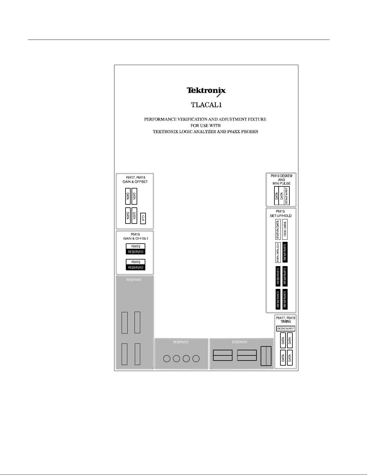
Adjustment Procedures
5- 4
Figure 5- 1: TLACAL2 test fixture connections
TLA5000 Series Service Manual
Page 65

Module+Probe Timing Procedures
The Module+Probe Timing procedures consist of the deskew adjustments. These
procedures are required to adjust the logic analyzer. These procedures use the
logic analyzer probes connected to the Deskew and Minimum Pulse connections
on the test fixture.
Adjustment Procedures
Equipment Setups
Start the Software
These procedures require the same setups as described in the Performance
Verification chapter of this manual. It is assumed that the logic analyzer is
already connected to the test fixture and that the performance verification
software is installed on the hard disk of the logic analyzer.
NOTE. To obtain the best results, keep the probes connected to the logic analyzer
and only move the connections on the test fixture.
Complete the following steps to start the software and to run the adjustments:
1. Exit the TLA application.
2. Double-click the Performance Verification icon on the desktop. An applica-
tion window similar to Figure 5--2 appears.
TLA5000 Series Service Manual
Figure 5- 2: Performance verification soft ware startup window
3. Click the Adjustment button to start the software. An Adjustment dialog box
similar to Figure 5--3 on page 5--6 appears.
5- 5
Page 66

Adjustment Procedures
4. Verify that Deskew is selected under the Module+Probe Timing Procedures.
5- 6
Figure 5- 3: Default Adjustment procedure dialog box
5. Click the Next button at the bottom of the dialog box to display the probe
connection instructions. Follow the on-screen instructions to connect the
probes from the logic analyzer to the test fixture. If necessary, refer
Figure 5--4 on page 5--7 and to the test fixture label to determine the correct
probe connection.
NOTE. When connecting the P6419 Logic Analyzer probes, make sure that the
alignment pin on the probe head aligns with the hole on the test fixture. Tighten
the probe head screws by alternating between them until they are finger tight (no
more than 1 in-lbs of torque).
6. Click the Next button to begin the procedures.
The software will begin the adjustment procedures and display the results of
the first 34 channels in the window.
TLA5000 Series Service Manual
Page 67

Adjustment Procedures
TLA5000 Series Service Manual
Figure 5- 4: Deskew procedure probe connections
NOTE. If any failures occur, you must complete the entire test sequence. Do not
click the Back button; otherwise the test results will be incorrect. Address the
problem and then restart the Deskew procedures.
In some cases the software will detect a failure and automatically redo the test
until it passes or times out and stops the test. You should only be concerned for a
test that continuously fails.
5- 7
Page 68

Adjustment Procedures
7. Click the Next button.
8. If you have a 34-channel logic analyzer, go to step 9. If your instrument has
more than 34 channels, connect the next probe as indicated by the software
instructions and then click the Next button to start testing the next probe
input section.
9. After the tests have completed, click the Next button to save the deskew
adjustment values.
10. Click the Next button to open the Finish dialog box where you can save the
results.
11. Click the Finish button to finish the procedure and return to the startup
window.
Completing the Adjustment Steps
After completing the adjustment procedures, you should always run the
Performance Verification Procedures to verify that the all parameters are within
the allowable specifications. If any of the adjustment and performance verification procedures fail, further service may be necessary. Contact your local
Tektronix service center for recommended action.
5- 8
TLA5000 Series Service Manual
Page 69

Maintenance
Preventing ESD
This chapter contains the information needed to do periodic and corrective
maintenance on the logic analyzer.
To repair the instrument, you must exchange or replace the failed part; this
manual does not provide component-level procedures for isolating components
on the failed part.
The information in this chapter is designed for use by qualified service personnel. Read the Safety Summary at the front of this manual before attempting any
procedures in this chapter.
When performing any service which requires internal access to the logic
analyzer, adhere to the following precautions to avoid damaging internal circuit
boards and their components due to electrostatic discharge (ESD).
CAUTION. Many components within the chassis are susceptible to staticdischarge damage. Service the chassis only in a static-free environment.
Observe standard handling precautions for static-sensitive devices while
servicing the chassis.
Always wear a grounded wrist strap, or equivalent, while servicing the chassis.
H Minimize handling of static-sensitive circuit boards.
H Transport and store static-sensitive circuit boards in their static protected
containers or on a metal rail. Label any package that contains static-sensitive
boards.
H Discharge the static voltage from your body by wearing a grounded antistatic
wrist strap while handling these circuit boards. Service static-sensitive circuit
boards only at a static-free work station.
H Nothing capable of generating or holding a static charge should be allowed
on the work station surface.
H Handle circuit boards by the edges when possible.
H Do not slide the circuit boards over any surface.
H Avoid handling circuit boards in areas that have a floor or work-surface
covering capable of generating a static charge.
TLA5000 Series Service Manual
6- 1
Page 70

Maintenance
WARNING. To avoid electric shock, always power off the instrument and
disconnect the power cord before cleaning or servicing the instrument.
Inspection and Cleaning
The logic analyzer is inspected mechanically and electrically before shipment. It
should be free of marks or scratches and should meet or exceed all electrical
specifications. To confirm this, inspect the chassis for physical damage incurred
during transit. Retain the packaging in case shipment for repair is necessary. If
there is damage or deficiency, contact your local Tektronix representative.
Cleaning procedures consist of exterior and interior cleaning of the chassis.
Clean the chassis as needed, based on the operating environment.
Interior Cleaning
Exterior Cleaning
Use a dry, low-velocity stream of air to clean the interior of the chassis. Use a
soft-bristle, nonstatic-producing brush for cleaning around components. If you
must use a liquid for minor interior cleaning, use a 75% isopropyl alcohol
solution and rinse with deionized water.
Clean the exterior surfaces of the chassis with a dry lint-free cloth or a softbristle brush. If any dirt remains, use a cloth or swab dipped in a 75% isopropyl
alcohol solution. Use a swab to clean narrow spaces around controls and
connectors. Do not use abrasive compounds on any part of the chassis that may
damage the chassis.
Clean the On/Standby switch using a dampened cleaning towel. Do not spray or
wet the switch directly.
CAUTION. Avoid getting moisture inside the instrument during exterior cleaning;
use just enough moisture to dampen the cloth or swab.
Do not wash the front-panel On/Standby switch. Cover the switch while washing
the instrument.
Use only deionized or distilled water when cleaning. Use a 75% isopropyl
alcohol solution as a cleanser and rinse with deionized or distilled water.
6- 2
Do not use chemical cleaning agents; they may damage the chassis. Avoid
chemicals that contain benzene, toluene, xylene, acetone, or similar solvents.
TLA5000 Series Service Manual
Page 71

Maintenance
Flat Panel Display
Cleaning
The logic analyzer display is a soft plastic display and must be treated with care
during cleaning.
CAUTION. To prevent damage to the flat panel display, do not use improper
cleaning agents or methods.
Avoid using abrasive cleaners or commercial glass cleaners to clean the display
surface.
Avoid spraying liquids directly on the display surface.
Avoid scrubbing the display with excessive force.
Clean the flat panel display surface by gently rubbing the display with a
clean-room wipe (such as Wypall Medium Duty Wipes, #05701, available from
Kimberly-Clark Corporation).
If the display is very dirty, moisten the wipe with distilled water or a 75%
isopropyl alcohol solution and gently rub the display surface. Avoid using excess
force or you may damage the plastic display surface.
TLA5000 Series Service Manual
6- 3
Page 72

Maintenance
6- 4
TLA5000 Series Service Manual
Page 73

Removal and Installation Procedures
This section contains procedures for removal and installation of field-replaceable
parts. This section is set up as a series of tasks.
Preparation
WARNING. Before performing this or any other procedure in this manual, read
the Safety Summary found at the beginning of this manual.
T o prevent possible injury to service personnel or damage to the logic analyzer,
read Installation in Chapter 2, and Preventing ESD on page 6--1.
WARNING. Before performing any procedure in this subsection, disconnect the
power cord from the line voltage source. Failure to do so could cause serious
injury or death.
General Instructions
NOTE. Read the following general instructions before removing a part.
Following these instructions helps ensure that you remove the part to be serviced
while removing the minimum number of additional parts.
First read over the Summary of Procedures that follows to understand how the
procedures are grouped. Then see Table 6--1, page 6--6 for a list of the tools
needed to remove and install replaceable parts in this logic analyzer.
If you are removing a part for service, begin by looking up the procedure for that
part. If any procedures are listed as required in advance in order to gain access to
the part, perform those procedures first.
TLA5000 Series Service Manual
6- 5
Page 74
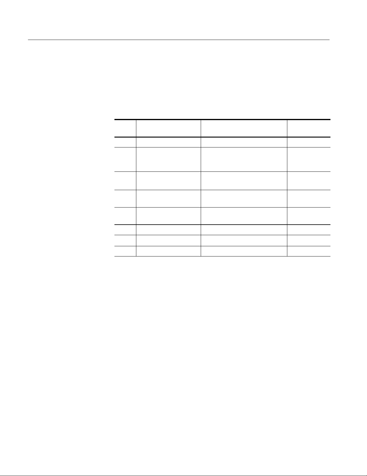
Removal and Installation Procedures
Equipment Required
Most parts in this logic analyzer can be removed using a screwdriver with a T-15
Torx tip.
Table 6- 1: Tools required for module removal
Accessories Pouch
Item
no.
1 Screwdriver handle Accepts Torx-driver bits 620-440
2 T-15 Torx tip Used for removing most of the
3
4 #0 Phillips screwdriver Screwdriver for removing small
5 #1 Phillips screwdriver Screwdriver for removing small
6 Angle-Tip Tweezers Used to remove front panel knobs Standard tool
7
8
Name Description
instrument’s screws. Torx-driver bit
for T-15 size screw heads
1
/8inch flat-bladed
screwdriver
3
/
inch nut driver
16
9
/16inch open-end wrench Used to remove BNC nuts Standard tool
Screwdriver for unlocking cable
connectors
Phillips screws, CD, floppy drive
Phillips screws, hard drive
Used to remove the nut posts Standard tool
General tool
number
640-247
Standard tool
Standard tool
Standard tool
You must remove the accessories pouch to access the covers on the instrument.
The remaining procedures assume that you have removed the accessories pouch.
6- 6
1. Open the pouch and located the two snaps on the inside front side of the
pouch.
2. Gently pull on each of the two tabs to unsnap the front of the pouch.
3. At the rear of the instrument, peel off the Velcro that holds the pouch to the
instrument.
4. Set the pouch aside.
5. To reinstall the pouch, perform these steps in reverse order. Tighten the T-15
Torx-drive screws to 8-in lbs.
TLA5000 Series Service Manual
Page 75

Trim and Covers
Removal and Installation Procedures
Remove the trim and covers as shown in Figures 6--1 on page 6--9, by
following this procedure.
1. Turn the logic analyzer off.
2. Remove the power cord and all probes.
3. Remove the top cover trim.
a. Remove the two T-15 Torx-drive screws that secure the top cover trim to
the instrument.
b. Remove the snap studs from the top cover.
c. Slide the trim panel toward the rear of the instrument allowing the tabs
to clear the cover openings, then pull out to remove the panel from the
instrument (you may need to loosen the two top black feet on the back of
the instrument if the cover does not come off easily).
4. Remove the carrying handle and left side trim.
NOTE. For many service operations you do not need to remove the left panel.
a. Remove the T-15 Torx-drive screws that secure the handle to the
instrument. Remove the handle.
b. Remove the two T-15 Torx-drive screws that secure the left side trim to
the bottom of the instrument.
c. Slide the trim panel toward the rear of the instrument allowing the tabs
to clear the cover openings, then pull out to remove the panel from the
instrument.
5. Remove the right side trim.
NOTE. When you remove the CD Drive trim, notice the notches in the trim that
provide the clearance for the chassis screws located under the trim. When you
replace the trim, make sure that you orient the trim with the notches in the
correct location. Otherwise the trim may not fit properly.
a. Remove the CD Drive trim by inserting a flat blade screwdriver in the
bottom slot of the CD trim and gently prying the trim piece out of the
side panel. Pull the trim up and out from the instrument.
TLA5000 Series Service Manual
b. Remove the two T-15 Torx-drive screws that secure the right side trim to
the bottom of the instrument.
6- 7
Page 76

Removal and Installation Procedures
6. Remove the VGA Panel by gently pulling the trim up and out from the
7. Remove the front panel trim.
NOTE. You should not need to remove the front panel trim unless you are
servicing the display, front panel assembly, or the Acquisition board.
c. Slide the trim panel toward the rear of the instrument allowing the tabs
to clear the cover openings, then pull out to remove the panel from the
instrument.
instrument.
a. To prevent the On/Standby button from falling out of the front panel
trim, place a piece of tape over the button.
b. Remove the three T-15 Torx-drive screws that secure the front panel trim
to the bottom of the instrument.
c. Grasp the trim ring by its top edge and pull toward you to detach the
three plastic snaps. (Alternatively, you can use a spudger tool to help you
detach the snaps.)
d. Grasp the trim ring by its side edges and slide it back and forth to release
the snap in the middle of the trim ring. The snap is at the lower right
corner of the display.
e. Pull off the trim ring.
8. Lift off the acquisition trim.
9. Reinstall the trim and covers by reversing the preceding steps to reinstall the
appropriate trim. Tighten the T-15 Torx-drive screws to 8-in lbs.
6- 8
TLA5000 Series Service Manual
Page 77

T-15 Torx-drive
screws (2)
Removal and Installation Procedures
Accessory
pouch
Top cover trim
Left side
panel
Acquisition trim
Front panel trim
Carrying handle
VGA panel
Right side
panel
CD-drive trim
T-15 Torx-drive
screws (2)
T-15 Torx-drive
screws (3)
Figure 6- 1: Trim and covers
TLA5000 Series Service Manual
Front panel cover
6- 9
Page 78

Removal and Installation Procedures
Right-Side Cover
Remove the right-side cover to access most of the internal components of the
instrument. Refer to Figure 6--2 while removing the right-side cover.
1. Remove the top and right trim to access the right-side cover.
NOTE. All mounting screw holes are indicated by a star etched around the
mounting hole.
2. Remove the 15 T-15 Torx-drive screws that secure the cover to the top and
3. Remove the cover.
CAUTION. Take care not to bind or snag the covers on the internal cabling as you
remove or install.
right sides of the chassis.
4. To reinstall the right-side cover reverse steps 1 through 3. Tighten the T-15
Torx-drive screws to 8-in lbs.
Tab
Right side cover
T-15 Torx-drive
screws (14)
Figure 6- 2: Right-side cover removal
6- 10
TLA5000 Series Service Manual
Page 79

Bottom Covers
Removal and Installation Procedures
NOTE. You should only need to remove the bottom covers when servicing the
Acquisition board.
1. Remove the top, left, and right trim covers.
2. Remove the bottom cover (with feet) as shown in Figure 6--3 on page 6--12
by following this procedure.
3. Remove the two T-15 Torx-drive screws that secure the bottom cosmetic
cover to the instrument.
4. Remove the bottom cosmetic cover.
5. Remove the seven T-15 Torx-drive screws that secure the bottom cover to
the instrument.
6. Remove the bottom cover.
7. To reinstall the bottom cover, reverse the above procedures. Tighten the T-15
Torx-drive screws to 8-in lbs.
NOTE. When reinstalling the bottom sheet metal cover, make sure that you install
the cover with the etched stars around the mounting holes on the outside. If you
install the cover upside down, then the vent holes will not line up with the holes
on the bottom cosmetic cover and you will not be able to install all screws.
TLA5000 Series Service Manual
6- 11
Page 80

Removal and Installation Procedures
Bottom metal
cover
Figure 6- 3: Bottom cover removal
T-15 Torx-drive
screws (9)
Bottom cosmetic
cover
6- 12
TLA5000 Series Service Manual
Page 81

Adding Memory
Removal and Installation Procedures
To add memory to your logic analyzer, follow these instructions.
1. Remove the top and right trim and top-right covers by following the
procedure on page 6--7.
2. Install the memory in the location shown in Figure 6--4.
Memory board (s)
Battery
Battery
TLA5000 Series Service Manual
Figure 6- 4: Memory board and battery location
3. Reinstall the trim and covers.
4. Verify the operation by following the procedure on page 6--35.
The battery type is CR2032 and is located directly below the memory boards.
Remove the top and right trim covers and the top-right cover to access the
battery. Refer to Figure 6--4 to locate the battery. Disengage the latch and remove
the battery from its holder. Dispose of the battery properly.
6- 13
Page 82

Removal and Installation Procedures
Locator Diagram
Use Figure 6--5 to locate the components for the remaining removal and
installation procedures.
Fans
Mother board
Hard disk drive
Floppy disk
drive
Interface board
Display module
assembly
Figure 6- 5: Locator diagram
Front panel
assembly
Acquisition
board
Power supply assembly
CD-drive adapter board
CD-drive
6- 14
TLA5000 Series Service Manual
Page 83

Floppy Disk Drive
Removal and Installation Procedures
1. Remove the top and right trim and the top-right cover.
2. Locate the Floppy Disk Drive in the locator diagram in Figure 6--5 on
page 6--14.
3. Set the instrument so its bottom is down on the work surface and the front
panel is facing you.
4. Remove the cable from the back of the floppy disk drive.
5. Remove the two T-15 Torx-drive screws that secure the floppy disk drive
assembly to the chassis.
6. Use a #0 Phillips screwdriver to remove the two small Phillips screws that
secure the floppy disk drive assembly to the bracket (see Figure 6--6).
7. Remove the floppy drive from the bracket.
Floppy drive
bracket
#0 Phillips
screws (2)
Floppy drive
Figure 6- 6: Floppy disk drive removal
8. To reinstall the floppy disk drive, reverse steps 1 through 7. Tighten the T-15
Torx-drive screws to 8-in lbs; tighten the Phillips screws to 2.5-in lbs.
TLA5000 Series Service Manual
6- 15
Page 84

Removal and Installation Procedures
Hard Disk Drive
1. Remove the top and right trim and the top-right cover.
2. Set the instrument so its bottom is down on the work surface and the front
3. Locate the Hard Disk Drive in the locator diagram in Figure 6--5 on
4. Remove the two T-15 Torx-drive screws that secure the hard disk drive to the
5. Pull the hard disk drive away from the chassis so that you can disconnect the
6. Disconnect the ribbon and power cables and then remove the hard disk drive
7. Remove the two T-15 Torx-drive screws that secure the bracket to hard disk
panel is facing you.
page 6--14.
chassis.
ribbon and power cables.
from the chassis.
drive.
CD Drive
8. To reinstall the hard disk drive, reverse steps 1 through 7. When installing
the assembly in the chassis, align the two tabs from the bracket to the slots in
the chassis before tightening the Torx-drive screws. Tighten the T-15
Torx-drive screws to 8-in lbs.
1. Remove the top and right trim and the top-right cover.
2. Set the instrument so its bottom is down on the work surface and the front
panel is facing you.
3. Locate the CD Drive in the locator diagram in Figure 6--5 on page 6--14.
4. Remove the single T-15 Torx-drive screw that secures the CD Drive
assembly to the chassis.
5. Pull the assembly away from the chassis so that you can disconnect the
ribbon and power cables.
6. Disconnect the ribbon and power cables and then remove the hard disk drive
from the chassis.
7. Remove the four Phillips screws that secure the CD drive to the bracket.
6- 16
8. Gently pull the CD drive away from the connector and remove the drive
from the bracket.
TLA5000 Series Service Manual
Page 85

Display
Removal and Installation Procedures
9. Remove the two Phillips screws that secure the CD drive adapter board to
the back of the CD drive.
10. Remove the CD drive adapter board from the CD drive.
11. To reinstall the hard disk drive, reverse steps 1 through 10. When installing
the assembly in the chassis, align the two tabs from the bracket to the slots in
the chassis before tightening the Torx-drive screws. Tighten the T-15
Torx-drive screw to 8-in lbs; tighten the Phillips screws to 2.0-in lbs.
1. Remove the trim and covers by following the procedure on page 6--7.
CAUTION. To avoid damage to the front panel Standby/On switch assembly, do
not set the Display module assembly on a work surface. Sliding the instrument
over the edge of the work surface could break off the Standby/On switch
assembly.
2. Remove the four T-15 Torx-drive screws that secure the Display assembly to
the chassis as shown in Figure 6--7, page 6--18.
3. Grasp the top edge of the Display assembly and pull forward far enough to
allow access to the flex cable connectors.
4. Disconnect the two flex cables from the display assembly. Remove the
display module assembly from the instrument.
5. To install the display, do steps 1 through 4 in reverse order. Tighten the T-15
Torx-drive screws to 8-in lbs.
TLA5000 Series Service Manual
6- 17
Page 86

Removal and Installation Procedures
T-15 Torx-drive
screws (4)
Finger relief
Finger relief
Flex cable
Display assembly
Display Adapter Board
Figure 6- 7: Flat panel display assembly removal
To remove the display adapter board perform the following:
1. Remove the trim and covers by following the procedure on page 6--7.
2. Remove the display assembly by following the procedure on page 6--17.
3. Remove the Display Adapter Board: See Figure 6--8, page 6--19.
4. Refer to Figure 6--8 on page 6--19 and disconnect the cables from the
Display Adapter board.
5. Remove the three T-15 Torx-drive screws that secure the Display Adapter
circuit board to the Display assembly.
6. Remove the Display Adapter from the assembly.
7. Reinstallation: Reverse steps 1 and 6 to reinstall the board. Tighten the T-15
Torx-drive screws to 8-in lbs.
6- 18
TLA5000 Series Service Manual
Page 87

Inverter Adapter cable
Screws (2)
T-15 Torx-drive
Inverter board
screws (3)
Removal and Installation Procedures
J5
Display adapter board
J4
J7
J3
J2
Figure 6- 8: Display adapter board removal
Standby/On Switch Flex Circuit
1. Remove the trim and covers by following the procedure on page 6--7.
2. Remove the display assembly by following the procedure on page 6--17.
3. Peel the Standby/On switch flex circuit away from the front of the display
assembly.
4. Disconnect the flex circuit from the Display Adapter circuit board.
5. Grasp the flex circuit and pull it out of the Display assembly.
6. To reinstall the Standby/On Switch.
a. Remove the protective backing on the new Standby/On switch flex
circuit.
b. Slide the connector end of the Standby/On switch flex circuit through the
slot in the Display assembly. Make sure the flex circuit connector aligns
to the connector on the Display Adapter circuit board.
TLA5000 Series Service Manual
6- 19
Page 88

Removal and Installation Procedures
7. Reinstall the display assembly and then the trim and covers.
Front-Panel Knobs
1. Set the instrument so its bottom is down on the work surface and its front is
c. Align the holes in the flex circuit to the two index posts on the front side
of the Display assembly.
d. Firmly press the flex circuit to the Display assembly chassis surface.
facing you.
2. Remove the knob(s): Grasp any knob you want to remove and pull it straight
out from the front panel
the knob and the front panel. Insert the angled-tip tweezers between the knob
and front panel and use them to remove the knob. See Figure 6--9.
1
@4inch to create some clearance between the base of
6- 20
Figure 6- 9: Knob removal
CAUTION. To prevent damage to the encoders located onto the circuit board,
apply pressure to the encoders while pushing the knob on the shaft.
3. To reinstall the knob, align the knob to the shaft and push it in until it snaps.
TLA5000 Series Service Manual
Page 89

Front Panel Assembly
Removal and Installation Procedures
1. Remove the trim and covers by following the procedure on page 6--6.
2. Set the instrument so its bottom is down on the work surface and its front
panel is facing you.
3. Remove the six T-15 Torx-drive screws that secure the Front panel assembly
to the front chassis. See Figure 6--10, page 6-- 22.
4. Grasp the top of Front Panel assembly and pull forward to allow access to
the ribbon cable connector on the front panel board.
1
5. Use the
lock up to disconnect the flex cable from the display module assembly. See
Figure 6--11, page 6--23. Note the connector’spin1indexmarkandtheblack
stripe on the cable for later reassembly.
6. Pull the Front Panel assembly forward and remove from the instrument.
7. To reinstall the front panel assembly, do steps 1 through 6 in reverse order.
Tighten the T-15 Torx-drive screws to 8-in lbs.
@8inch flat-bladed screwdriver to carefully lift the cable connector
TLA5000 Series Service Manual
6- 21
Page 90

Removal and Installation Procedures
support tab (2)
Floppy disk
T-15 Torx-drive
screws (6)
Figure 6- 10: Front panel assembly removal
Ribbon cable
6- 22
TLA5000 Series Service Manual
Page 91

Screwdriver
Removal and Installation Procedures
Black stripe
toward connector
Front Panel Board
Figure 6- 11: JR1 flex cable connector removal
1. Remove the trim and covers by following the procedure on page 6--6.
2. Remove the front panel knobs.
3. Remove the front panel assembly.
4. Remove the eight T-15 Torx-drive screws that secure the Front panel board
to the Front panel assembly. See Figure 6--12, page 6--24.
5. Pry the board up off the alignment studs. Place a Use flat bladed screwdriver
in the pry point access holes to pry the board up from the assembly.
6. To reinstall the front panel board do steps 1 through 5 in reverse order.
Tighten the T-15 Torx-drive screws to 8-in lbs.
TLA5000 Series Service Manual
6- 23
Page 92

Removal and Installation Procedures
Front Panel Keypad
1. Remove the trim and covers by following the procedure on page 6--6.
2. Remove the front panel knobs.
3. Remove the front panel assembly.
4. Remove the front panel board.
5. Remove the Front Panel keypad:
6. Pull on each of the keypad support guides to separate the keypad from the
7. Remove the keypad from the front panel board.
Front panel board. Use a pair of tweezers or equivalent tool to pull the
twelve keypad support guides.
Front panel board
T-15 Torx-drive
screws (8)
Alignment stud Pry point
access hole
Pry point
access hole
Figure 6- 12: Front panel board & keyboard removal
Keypad support
guide (13)
Keypad
6- 24
TLA5000 Series Service Manual
Page 93

Fans
Removal and Installation Procedures
CAUTION. When removing or installing the keypad, make sure you do not touch
the switch contact with your fingers. The oils in your fingers will degrade or
damage the switch contacts. To help prevent damage to the keypad use cotton
gloves when removing or installing the keyboard pad.
8. To reinstall the keypad, do steps 1 through 7 in reverse order. Tighten the
T-15 Torx-drive screws to 8-in lbs.
1. Remove the top, right, and left trim and the top-right cover.
2. Set the instrument so its bottom is down on the work surface and the front
panel is facing you.
3. Locate the fans in the locator diagram in Figure 6--5 on page 6--14.
4. Remove the four plastic fasteners that secure each of the fans to the chassis.
See Figure 6--13 on page 6--26.
NOTE. A wire cutter can help you remove each fastener. First, use the cutter to
pry up and retract the fastener head. Then use it to remove the fastener body.
Be careful to only pry with the wire cutters and NOT to cut!
5. Lift the fan cable up and out from the cable clamp.
NOTE. A needle-nose priers can serve as an effective tool to remove the cable
clamp if you use it to carefully squeeze the clamp’s top and bottom latches
6. Disconnect the fan cable from the Interface board.
7. Lift the fan assembly up and out from the chassis.
8. To reinstall the fan assembly, do steps 4 through 7 in reverse order.
CAUTION. Take care when handling the fans; the fan blades are brittle and can
be easily damaged.
TLA5000 Series Service Manual
6- 25
Page 94

Removal and Installation Procedures
Plastic fastener
Plastic fasteners
Power Supply
Left side of the instrument
Figure 6- 13: Fan fastener removal
1. Remove the top and right trim and the top-right cover.
2. Remove the floppy disk drive assembly.
3. Set the instrument so its bottom is down on the work surface and the back is
facing you.
4. Locate the power supply in the locator diagram in Figure 6--5 on page 6--14.
5. Refer to Figure 6--14, on page 6--27 and remove the four T-15 Torx-drive
screws that secure the power supply to the back of the chassis.
6- 26
TLA5000 Series Service Manual
Page 95

Removal and Installation Procedures
6. Remove the single T-15 Torx-drive screw that secures the power supply to
the right side of the chassis.
7. Move the power supply towards the front of the instrument to disengage the
power connector from the back panel. Then lift the power supply out of the
chassis so that you can access the cables and disconnect them from the
circuit boards and hard disk drive.
8. Lift the power supply away from the chassis and guide the cables out.
9. To reinstall the power supply do steps 1 through 8 in reverse order. Tighten
the T-15 Torx-drive screws to 8-in lbs.
Pull the sheet metal away from the
power supply just enough to clear and
lift the power supply up
Disconnect from the
Interface board and
hard disk drive
Figure 6- 14: Power supply removal
T-15 Torx-drive
screws (4)
Power supply
T-15 Torx-drive
screw (1)
TLA5000 Series Service Manual
6- 27
Page 96

Removal and Installation Procedures
Interface Board and Mother Board Cable Connections
Figure 6--15 shows the location of cables and cable connectors for the Interface
board and the Mother board. Pay close attention to this diagram and the cable
connections when you disassemble and reassemble the instrument.
Mother board
HD/CDRW
cables
J730/ATX
USB cable
Hard disk drive
J510/CDRW drive
power cable
Inverter
adapter cable
J910/Front panel
PWR cable
J3
J2
J850/Bridge
cable
Front panel
JR410/Front
panel cable
Interface board
cable
J941
J940
J430/CPU
power cable
CD-drive
J450/Power
supply cable
Mother board
Floppy disk
drive
J420/Dual
USB cable
Figure 6- 15: Interface board and Mother board cable connections
6- 28
TLA5000 Series Service Manual
Page 97

Mother Board
Removal and Installation Procedures
1. Remove all the trim, top-right cover, and bottom covers.
2. Remove the floppy disk drive assembly.
3. Set the instrument so its bottom is down on the work surface and the back is
facing you.
4. Remove the power supply.
NOTE. The Mother board and rear chassis is removed as one assembly.
5. Remove the eight T-15 Torx-drive screws that secure the Mother board
assembly to the side of the chassis, see Figure 6--16, on page 6--30.
NOTE. You only need to separately remove the cord-wrap post if you plan to
replace the sheet metal and reuse the posts. If you do plan to replace the sheet
metal, then remember that it has stickers with important information on it such
as the serial #, option label and safety data.
6. Disconnect the four cables and from the Mother board assembly.
7. Carefully lift the assembly out of the chassis.
8. Disconnect the remaining two cables at the bottom of the assembly.
9. Set the Mother board assembly so the bottom is down on the work surface
and the connector panel is facing you.
10. Remove the six jack screws that secure the Mother board connectors to the
connector panel of the rear chassis.
11. Remove the six T-15 Torx-drive screws that secure the Mother board to the
rear chassis.
12. Carefully lift the Mother board out of the rear chassis.
13. To reinstall the Mother board do steps 1 through 12 in reverse order. Tighten
the T-15 Torx-drive screws to 8-in lbs.
TLA5000 Series Service Manual
6- 29
Page 98

Removal and Installation Procedures
Mother board
assembly
Front of the
instrument
VGA bracket
Jack screws (2)
T-15 Torx-drive
screws (8)
Mother board
Figure 6- 16: Mother board removal
T-15 Torx-drive
screws (6)
Jack screws (6)
6- 30
TLA5000 Series Service Manual
Page 99

Interface Board
Removal and Installation Procedures
1. Remove all the trim, top-right cover, and bottom covers.
2. Remove the floppy disk drive assembly.
3. Remove the power supply.
4. Remove the Mother board.
5. Set the instrument so its bottom is down on the work surface and the top
panel is facing you.
6. Remove the two jack screws that secure the VGA connector to the bracket
(see Figure 6--16 on page 6--30) and then remove the bracket and set it aside.
7. Refer to Figure 6--17 on page 6--32 and disconnect all cables from the
Interface board. Note the location of each cable so you can reconnect them
properly during reassembly.
8. Remove the six T-15 Torx-drive screws that secure the Interface board to the
chassis.
CAUTION. Do not remove the screw underneath the power supply bracket next to
the multi-pin connector (See Figure 6--17 on page 6--32). The screw secures an
indexing pin used to align the multi-pin connector to the Acquisition board.
9. Grasp the Interface board (see Figure 6--17) and carefully pull the board up
to disconnect the multi-pin connector underneath the power supply bracket.
Once you have cleared the connector, remove the board from the chassis.
10. When installing the Interface board, set the board in place and align the
multi-pin connector under the power supply bracket using the guide pin.
Gently press the board into place to seat the connector between the Interface
board and the Acquisition board.
11. Complete steps 8 through 1 in reverse order to complete the installation.
Tighten the T-15 Torx-drive screws to 8-in lbs. Tighten the jack screws to
4.0-in lbs.
TLA5000 Series Service Manual
6- 31
Page 100

Removal and Installation Procedures
Interface
board
T-15 Torx-drive screws (6)
Guide pin
6- 32
Figure 6- 17: Interface board removal
TLA5000 Series Service Manual
 Loading...