

Page 1

Thunderbolt Receiver Test
Application Manual
*P077173901*
077-1739-01
Page 2

Page 3

Thunderbolt Receiver Test
Application Manual
Register now!
Click the following link to protect your product.
www.tek.com/register
*P077173901*
077-1739-01
Page 4

Copyright © Tektronix. All rights reserved. Licensed software products are owned by Tektronix or its subsidiaries or suppliers, and are
protected by national copyright laws and international treaty provisions. Tektronix products are covered by U.S. and foreign patents, issued
and pending. Information in this publication supersedes that in all previously published material. Specifications and price change privileges
reserved.
TEKTRONIX and TEK are registered trademarks of Tektronix, Inc.
Contacting Tektronix
Tektronix, Inc.
14150 SW Karl Braun Drive
P.O. Box 500
Beaverton, OR 97077
USA
For product information, sales, service, and technical support:
• In North America, call 1-800-833-9200.
• Worldwide, visit to www.tek.com find contacts in your area.
Page 5

Table of Contents
Table of Contents
Welcome..................................................................................................................................................................................... 10
Getting help and support............................................................................................................................................................. 11
Related documentation........................................................................................................................................................ 11
Technical support................................................................................................................................................................. 11
Getting started.............................................................................................................................................................................12
Required equipment and accessories..................................................................................................................................12
Installing the software.......................................................................................................................................................... 12
Operating basics......................................................................................................................................................................... 14
Launch the application......................................................................................................................................................... 14
Close the application............................................................................................................................................................14
Launch Real-Time Oscilloscope.......................................................................................................................................... 14
Launch TekRxService.......................................................................................................................................................... 15
Application panels....................................................................................................................................................................... 16
Application panels overview.................................................................................................................................................16
Connections panel............................................................................................................................................................... 17
Settings panel...................................................................................................................................................................... 17
Basic settings................................................................................................................................................................18
Help panel............................................................................................................................................................................21
Calibrations panel................................................................................................................................................................ 21
TP3' Calibration............................................................................................................................................................ 22
TP3 Calibration............................................................................................................................................................. 36
SFV Calibration.............................................................................................................................................................45
Tests panel...........................................................................................................................................................................48
JTOL Test......................................................................................................................................................................48
Sensitivity Test.............................................................................................................................................................. 55
BER Test.......................................................................................................................................................................62
SFVT Test..................................................................................................................................................................... 69
Programmatic interface commands............................................................................................................................................ 74
SETTINGS:ANALYSIS:TOOL.............................................................................................................................................. 74
SETTINGS:RECALL............................................................................................................................................................ 74
SETTINGS:RECALL:STATUS............................................................................................................................................. 74
SETTINGS:RESTORE.........................................................................................................................................................75
SETTINGS:RESTORE:STATUS..........................................................................................................................................75
SETTINGS:RTS:NEGATIVECHANNEL...............................................................................................................................75
SETTINGS:RTS:POSITIVECHANNEL................................................................................................................................ 75
SETTINGS:RTS:SAMPLERATE.......................................................................................................................................... 76
SETTINGS:SAVE.................................................................................................................................................................76
SETTINGS:SAVE:STATUS.................................................................................................................................................. 76
SETTINGS:SIGTEST:FILENAME........................................................................................................................................ 77
SETTINGS:SIGTEST:FILEPATH......................................................................................................................................... 77
TP3PRIME:ACCM:RUN.......................................................................................................................................................77
TP3PRIME:ACCM:SETTING...............................................................................................................................................78
TP3PRIME:ACCM:STATUS.................................................................................................................................................78
TP3PRIME:DDJ:STATUS.................................................................................................................................................... 78
Thunderbolt Receiver Test Application Manual 5
Page 6

Table of Contents
TP3PRIME:DDJ:RUN.......................................................................................................................................................... 78
TP3PRIME:EYEDIAGRAM:PJ@FREQ............................................................................................................................... 79
TP3PRIME:EYEDIAGRAM:RUN......................................................................................................................................... 79
TP3PRIME:EYEDIAGRAM:STATUS................................................................................................................................... 79
TP3PRIME:EYEDIAGRAM:TYPE........................................................................................................................................80
TP3PRIME:PJ:RUN............................................................................................................................................................. 80
TP3PRIME:PJ:STATUS....................................................................................................................................................... 80
TP3PRIME:RJ:RUN.............................................................................................................................................................81
TP3PRIME:RJ:SETTING..................................................................................................................................................... 81
TP3PRIME:RJ:STATUS.......................................................................................................................................................81
TP3PRIME:TJ:RUN............................................................................................................................................................. 82
TP3PRIME:TJ:STATUS....................................................................................................................................................... 82
TP3PRIME:EH:STATUS...................................................................................................................................................... 82
TP3PRIME:ACDC:RUN....................................................................................................................................................... 82
TP3PRIME:ACDC:STATUS................................................................................................................................................. 83
TP3PRIME:AUTOCAL......................................................................................................................................................... 83
TP3PRIME:DELETE............................................................................................................................................................ 83
TP3PRIME:EQUIP:STATUS................................................................................................................................................ 84
TP3PRIME:EQUIP:INIT....................................................................................................................................................... 84
TP3PRIME:EH:RUN............................................................................................................................................................ 84
TP3PRIME:EH:SETTING.................................................................................................................................................... 85
TP3PRIME:OPEN................................................................................................................................................................85
TP3PRIME:PRESET:RUN................................................................................................................................................... 85
TP3PRIME:PRESET:STATUS............................................................................................................................................. 85
TP3PRIME:REPORT........................................................................................................................................................... 86
TP3PRIME:SAVE:COMMENTS...........................................................................................................................................86
TP3PRIME:SAVE:GENERATEDBY.....................................................................................................................................86
TP3PRIME:SAVE:ID............................................................................................................................................................ 87
TP3PRIME:WIZARD:CLOSE...............................................................................................................................................87
TP3PRIME:WIZARD:OPEN.................................................................................................................................................87
TBT:GEN..............................................................................................................................................................................87
TP3CAL:AUTOCAL..............................................................................................................................................................88
TP3CAL:CHKMANUALIL.....................................................................................................................................................88
TP3CAL:CTLE:ACQS.......................................................................................................................................................... 88
TP3CAL:CTLE:CHKCTLE................................................................................................................................................... 89
TP3CAL:CTLE:PJ@FREQ.................................................................................................................................................. 89
TP3CAL:CTLE:PRESET......................................................................................................................................................89
TP3CAL:CTLE:RUN............................................................................................................................................................ 90
TP3CAL:CTLE:STATUS.......................................................................................................................................................90
TP3CAL:DELETE................................................................................................................................................................ 90
TP3CAL:ENABLENEGDEEMBED.......................................................................................................................................91
TP3CAL:ENABLEPOSDEEMBED.......................................................................................................................................91
TP3CAL:EQUIP:STATUS.....................................................................................................................................................91
TP3CAL:EQUIP:INIT........................................................................................................................................................... 92
TP3CAL:IL:ACQS................................................................................................................................................................ 92
TP3CAL:IL:RUN...................................................................................................................................................................92
TP3CAL:IL:SCOPEACQS....................................................................................................................................................93
TP3CAL:IL:STATUS.............................................................................................................................................................93
TP3CAL:MANUALIL............................................................................................................................................................ 93
Thunderbolt Receiver Test Application Manual 6
Page 7

Table of Contents
TP3CAL:NEGDEEMBEDFILE............................................................................................................................................. 94
TP3CAL:OPEN.................................................................................................................................................................... 94
TP3CAL:POSDEEMBEDFILE............................................................................................................................................. 94
TP3CAL:REPORT................................................................................................................................................................94
TP3CAL:SAVE..................................................................................................................................................................... 95
TP3CAL:SAVE:COMMENTS............................................................................................................................................... 95
TP3CAL:SAVE:GENERATEDBY......................................................................................................................................... 95
TP3CAL:SAVE:ID.................................................................................................................................................................96
TP3CAL:SELECT:TP3PRIME..............................................................................................................................................96
TP3CAL:STRESSEDEYE:ACQS.........................................................................................................................................96
TP3CAL:STRESSEDEYE:FREQ.........................................................................................................................................96
TP3CAL:STRESSEDEYE:PJ@FREQ................................................................................................................................. 97
TP3CAL:STRESSEDEYE:RUN........................................................................................................................................... 97
TP3CAL:STRESSEDEYE:STATUS..................................................................................................................................... 97
TP3CAL:STRESSEDEYE:TYPE..........................................................................................................................................98
TP3CAL:WIZARD:CLOSE................................................................................................................................................... 98
TP3CAL:WIZARD:OPEN..................................................................................................................................................... 98
JTOLTEST:AMP:HIGH......................................................................................................................................................... 99
JTOLTEST:AMP:LOW..........................................................................................................................................................99
JTOLTEST:CUSTOM:MASK................................................................................................................................................ 99
JTOLTEST:DELETE...........................................................................................................................................................100
JTOLTEST:DUTTYPE........................................................................................................................................................ 100
JTOLTEST:FREQ:DEFAULT..............................................................................................................................................100
JTOLTEST:FREQCHK....................................................................................................................................................... 100
JTOLTEST:LINK.................................................................................................................................................................101
JTOLTEST:MASK:AMP......................................................................................................................................................101
JTOLTEST:OPEN...............................................................................................................................................................102
JTOLTEST:REPORT..........................................................................................................................................................102
JTOLTEST:RESULT...........................................................................................................................................................102
JTOLTEST:RESULT:DISPLAYTYPE.................................................................................................................................. 102
JTOLTEST:RUN................................................................................................................................................................. 103
JTOLTEST:RUN:STATUS.................................................................................................................................................. 103
JTOLTEST:SAVE............................................................................................................................................................... 103
JTOLTEST:SAVE:COMMENTS......................................................................................................................................... 104
JTOLTEST:SAVE:GENERATEDBY....................................................................................................................................104
JTOLTEST:SAVE:ID...........................................................................................................................................................104
JTOLTEST:SWAPLANE.....................................................................................................................................................104
JTOLTEST:TESTEDLANE................................................................................................................................................. 105
JTOLTEST:WIZARD:OPEN............................................................................................................................................... 105
SENSITIVITY:AMP:HIGH.................................................................................................................................................. 105
SENSITIVITY:AMP:LOW................................................................................................................................................... 106
SENSITIVITY:CUSTOM:MASK..........................................................................................................................................106
SENSITIVITY:DELETE...................................................................................................................................................... 106
SENSITIVITY:DUTTYPE................................................................................................................................................... 107
SENSITIVITY:FREQ:DEFAULT......................................................................................................................................... 107
SENSITIVITY:FREQCHK...................................................................................................................................................107
SENSITIVITY:LINK............................................................................................................................................................ 107
SENSITIVITY:MASK:AMP................................................................................................................................................. 108
SENSITIVITY:OPEN..........................................................................................................................................................108
Thunderbolt Receiver Test Application Manual 7
Page 8

Table of Contents
SENSITIVITY:REPORT..................................................................................................................................................... 108
SENSITIVITY:RESULT...................................................................................................................................................... 109
SENSITIVITY:RESULT:DISPLAYTYPE............................................................................................................................. 109
SENSITIVITY:RUN............................................................................................................................................................ 109
SENSITIVITY:RUN:STATUS..............................................................................................................................................109
SENSITIVITY:SAVE........................................................................................................................................................... 110
SENSITIVITY:SAVE:COMMENTS..................................................................................................................................... 110
SENSITIVITY:SAVE:GENERATEDBY............................................................................................................................... 110
SENSITIVITY:SAVE:ID.......................................................................................................................................................111
SENSITIVITY:SWAPLANE................................................................................................................................................. 111
SENSITIVITY:TESTEDLANE............................................................................................................................................. 111
SENSITIVITY:WIZARD:OPEN...........................................................................................................................................112
BERTEST:DELETE............................................................................................................................................................ 112
BERTEST:DUTTYPE......................................................................................................................................................... 112
BERTEST:LINK.................................................................................................................................................................. 112
BERTEST:OPEN................................................................................................................................................................113
BERTEST:PJ@FREQ........................................................................................................................................................ 113
BERTEST:REPORT........................................................................................................................................................... 113
BERTEST:RUN.................................................................................................................................................................. 114
BERTEST:SAVE:COMMENTS........................................................................................................................................... 114
BERTEST:SAVE:GENERATEDBY.....................................................................................................................................114
BERTEST:SAVE:ID............................................................................................................................................................ 114
BERTEST:SWAPLANE...................................................................................................................................................... 115
BERTEST:TESTEDLANE...................................................................................................................................................115
BERTEST:WIZARD:OPEN.................................................................................................................................................115
RXTEST:BERT:DEEMPHASIS...........................................................................................................................................116
RXTEST:BERT:PRESET.................................................................................................................................................... 116
RXTEST:BERT:PRESHOOT.............................................................................................................................................. 116
RXTEST:CALSEL:TP3....................................................................................................................................................... 116
RXTEST:CALSEL:TP3CALCHECK....................................................................................................................................117
RXTEST:CALSEL:TP3PRIME............................................................................................................................................117
RXTEST:CALSEL:TP3PRIMECALCHECK........................................................................................................................ 117
RXTEST:CONFIGTEST:ACCM.......................................................................................................................................... 118
RXTEST:CONFIGTEST:AMP............................................................................................................................................. 118
RXTEST:CONFIGTEST:PJ.................................................................................................................................................118
RXTEST:CONFIGTEST:PJ@FREQ...................................................................................................................................119
RXTEST:CONFIGTEST:RJ................................................................................................................................................ 119
RXTEST:CONFIGTEST:STRESSCONFIG........................................................................................................................ 119
RXTEST:CROSSTALK:AMP..............................................................................................................................................120
RXTEST:CROSSTALK:SOURCE...................................................................................................................................... 120
RXTEST:CROSSTALK:FAREND....................................................................................................................................... 120
RXTEST:CROSSTALK:NEAREND....................................................................................................................................121
RXTEST:DURATION..........................................................................................................................................................121
RXTEST:EXEPATH............................................................................................................................................................121
RXTEST:LOGIC................................................................................................................................................................. 122
RXTEST:PATTERN............................................................................................................................................................122
RXTEST:PORT.................................................................................................................................................................. 122
RXTEST:SSC.....................................................................................................................................................................123
RXTEST:SSC:DEVIATION.................................................................................................................................................123
Thunderbolt Receiver Test Application Manual 8
Page 9

Table of Contents
RXTEST:SSC:FREQUENCY............................................................................................................................................. 123
RXTEST:TIGERLAKE........................................................................................................................................................ 123
RXTEST:WIZARD:CLOSE.................................................................................................................................................124
SFVTTEST:CROSSTALK...................................................................................................................................................124
SFVTTEST:DELETE.......................................................................................................................................................... 124
SFVTTEST:DUTTYPE....................................................................................................................................................... 125
SFVTTEST:ITERATIONS...................................................................................................................................................125
SFVTTEST:LINK................................................................................................................................................................ 125
SFVTTEST:OPEN..............................................................................................................................................................126
SFVTTEST:REPORT......................................................................................................................................................... 126
SFVTTEST:RUN................................................................................................................................................................ 126
SFVTTEST:RUN:STATUS..................................................................................................................................................126
SFVTTEST:SAVE...............................................................................................................................................................127
SFVTTEST:SAVE:COMMENTS.........................................................................................................................................127
SFVTTEST:SAVE:GENERATEDBY...................................................................................................................................127
SFVTTEST:SAVE:ID..........................................................................................................................................................128
SFVTTEST:SWAPLANE.................................................................................................................................................... 128
SFVTTEST:TESTEDLANE................................................................................................................................................ 128
SFVTTEST:WIZARD:OPEN...............................................................................................................................................128
SFV:CALSEL:TP3 <CALNAME>....................................................................................................................................... 129
SFV:CALSEL:TP3CALCHECK <0/1>................................................................................................................................129
SFV:CALSEL:TP3PRIME <CALNAME>............................................................................................................................129
SFV:CALSEL:TP3PRIMECALCHECK <0/1>.....................................................................................................................129
SFV:OPEN.........................................................................................................................................................................130
SFV:REPORT.................................................................................................................................................................... 130
SFV:RUN <1/0>................................................................................................................................................................. 130
SFV:RUN:STATUS.............................................................................................................................................................131
SFV:SAVE:COMMENTS [string]........................................................................................................................................ 131
SFV:SAVE:GeneratedBy [string]........................................................................................................................................131
SFV:SAVE:ID [string]......................................................................................................................................................... 131
SFV:Save:Status................................................................................................................................................................132
SFV:WIZARD:CLOSE........................................................................................................................................................132
TBT_SFV:DELETE............................................................................................................................................................ 132
TBT_SFV:SAVE................................................................................................................................................................. 132
TBT_SFV:WIZARD:OPEN.................................................................................................................................................133
Index......................................................................................................................................................................................... 134
Thunderbolt Receiver Test Application Manual 9
Page 10
Welcome
The TBT3/TBT4 Rx application performs the test as per the Gen 2 / Gen 3 USB4 Electrical CTS Revision 1.02.
Welcome
Figure 1: TekRxTest - Thunderbolt4 Gen 2 / Gen 3 Rx application
Key features and benefits
• Calibration and Compliance Testing comes as a part of the receiver solution.
• Automated Calibration procedure is handy along with the ability to reload and rerun older Calibration files.
• Receiver BER, Signal Frequency Variations Training (SFVT), Jitter Tolerance (JTOL), and Sensitivity test for the DUT using the
Electrical Testing Tool (ETT) from USB-IF.
• Jointly with Anritsu BERT MP1900A series, the receiver solution provides the tools and flexibility required to visualize and control the
impairments, observe real-time eye performance for Thunderbolt3/4 devices at 10, 10.3125, 20 and 20.625 Gbps.
• The solution showcases the eye diagram at TP3’ and TP3 endpoints.
• Reliable and accurate results reduce the test execution time and minimize the skillset required to perform calibration and testing.
• Available tests can be run at TP3’ (Case 1) and TP3 (Case 2) test points and come with crosstalk feature.
• Detailed reports are at one’s disposal for all calibration and test modules.
Thunderbolt Receiver Test Application Manual 10
Page 11

Getting help and support
Getting help and support
Related documentation
The following documentation is available as part of the TBT3/4 Gen 2 / Gen 3 Rx receiver test application.
Table 1: Product documentation
Item Purpose Location
Application Help Application operation and User Interface
details
Technical support
Tektronix values your feedback on our products. To help us serve you better, please send us your suggestions, ideas, or comments on
your application or Real Time Oscilloscope. Contact Tektronix through mail, telephone, or the Web site. See Contacting Tektronix.
When you contact Tektronix Technical Support, please include the following information (be as specific as possible):
General information
Help panel of the application
• All instrument model numbers
• Hardware options, if any
• Modules used
• Your name, company, mailing address, phone number, and FAX number
• Please indicate if you would like to be contacted by Tektronix about your suggestion or comments.
Application specific information
• Software version number
• Description of the problem such that technical support can duplicate the problem
• If possible, save the setup files for all the instruments used and the application.
Thunderbolt Receiver Test Application Manual 11
Page 12

Getting started
Getting started
Required equipment and accessories
This section lists the accessories and test fixtures required to perform the tests.
Table 2: Required equipment and accessories
Equipment Vendor Type R/O Qty Description
MP1900A Anritsu Equipment Required 1 BERT
DPO72304SX or
DPO72304DX or Oscilloscope
of higher bandwidth
CIO – DPOJET plugin Tektronix Software Required 1 Pre-req option for TBT3/4
DIA-DPOJET Advanced
option
SDLA64 Tektronix Software Required 1 Pre-req option for TBT3/4
PMCABLE1M Tektronix Accessory Required 3 Precision Phase Matched Cable Pair, 1m
640-0961-000 Wilder Equipment Required 1 USB4 controller and fixture (USB4-TPA-UC-K)
ST2643 Fairview Microwave Accessory Required 4 SMP terminators
SM8852 Fairview Microwave Accessory Required 6 2.92mm (female) to SMP (female) Cable or
PCIe Gen4 ISI Fixture PCI-SIG Accessory Required 1 This will be replaced when an approved
0.8 m and 2 m USB Type-C
cables
RXSW-NLP-TBT34 or Tektronix Software Required 1 License; Thunderbolt 3 and 4 Receiver
RXSW-NL1-TBT34 or License; Thunderbolt 3 and 4 Receiver
RXSW-FLP-TBT34 or License; Thunderbolt 3 and 4 Receiver
RXSW-FL1-TBT34 License; Thunderbolt 3 and 4 Receiver
Tektronix Equipment Required 1 Tektronix Real time Oscilloscope Bandwidth
≥21GHz, ≥2-channel oscilloscope
Tektronix Software Required 1 Pre-req option for TBT3/4
Adapter
version is made available
Any USB-IF approved
cable
Accessory Required 1 each USB Type C Cables
automation software for TEK scopes and
Anritsu BERT; Perpetual; Node-Locked
automation software for TEK scopes and
Anritsu BERT; 1 year subscription; NodeLocked
automation software for TEK scopes and
Anritsu BERT; Perpetual; Floating
automation software for TEK scopes and
Anritsu BERT; 1 year subscription; Floating
Installing the software
Follow the below steps to download and install the latest TBT3/4 Gen 2 / Gen 3 TekRxTest application.
1. Go to www.tek.com.
Thunderbolt Receiver Test Application Manual 12
Page 13

Getting started
2. Click Downloads. In the Download menu, select DOWNLOAD TYPE as Software and enter TBT3/4 Gen 2 / Gen 3 Rx in the MODEL
OR KEYWORD field and click SEARCH.
3. Select the latest version of the software and follow the instructions to download.
4. Copy the executable file into the instrument to install the software (Real-time oscilloscope or PC).
5. Follow the installation instructions that is available in the website. The software is installed at
C:\ProgramFiles\Tektronix\BERTScope\RxTest60.
6. Click the shortcut icon on the desktop to launch the application.
Note:
• The TBT3/4 Gen 2 / Gen 3 TekRxTest application can be installed on a Tektronix real-time oscilloscope or a PC (Optional).
• You must install the TekRxService application in the real-time oscilloscope to successfully connect the application with the
real-time oscilloscope.
Thunderbolt Receiver Test Application Manual 13
Page 14
Operating basics
Operating basics
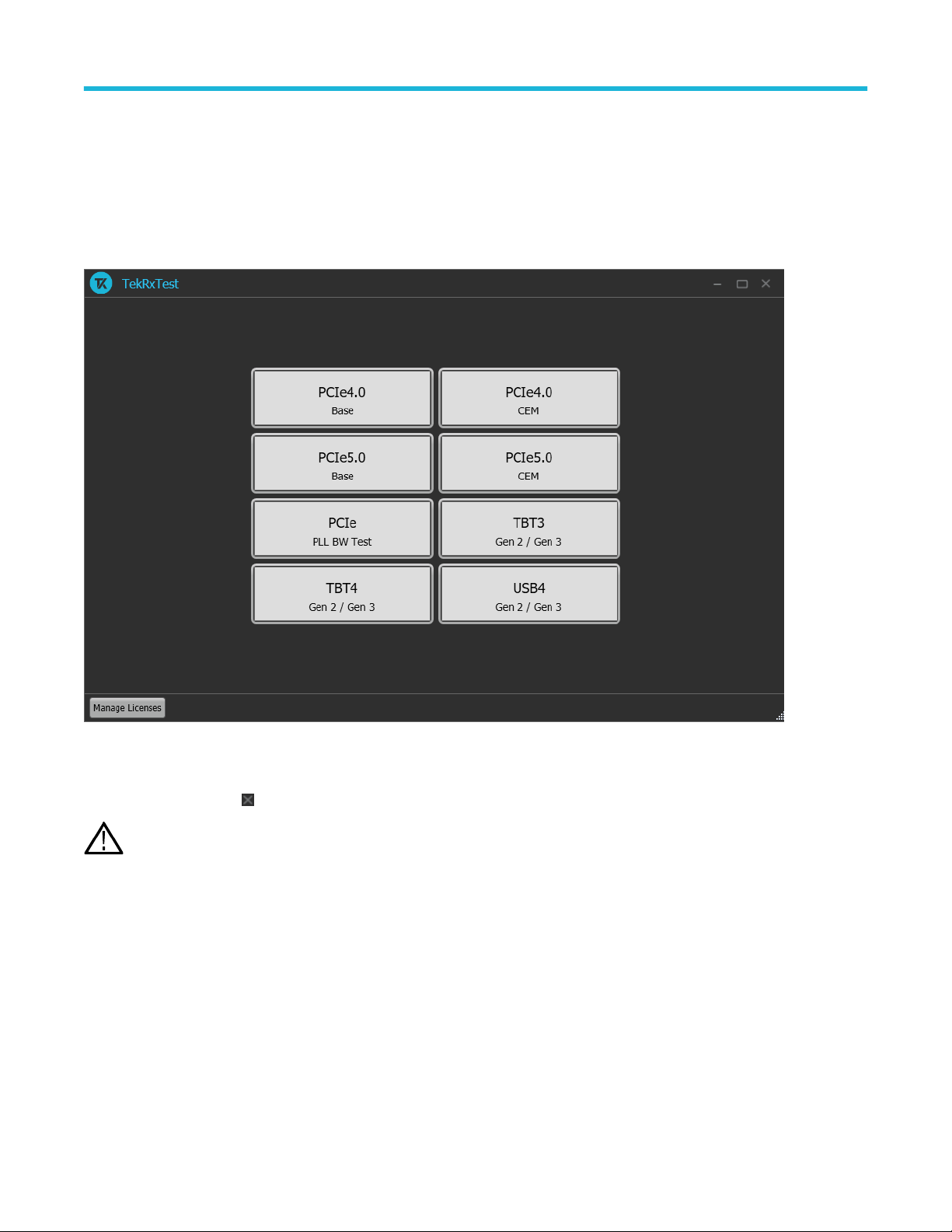
Launch the application
To launch the TBT3/4 Gen 2 / Gen 3 TekRxTest application, click the shortcut icon TekRxTest on the desktop and select TBT3 or TBT4
Gen 2 / Gen 3 in the application window.
Close the application
To exit the application, click on the application title bar. Follow on-screen instructions to save the unsaved session or test setup.
Using other methods to exit the application may result in abnormal termination of the application.
Note:
Launch Real-Time Oscilloscope
The TekVISA Socket Server application on the oscilloscope provides the necessary connectivity between the TekRxTest application
and scope. Although it is launched in the background when the scope boots up and the socket is initialized for communication, it is
recommended to verify the status by clicking on the Desktop Tray ―› TekVISA LAN Server Control as shown in the image below. If it is
ready to exchange data, then a wizard would appear as in the below image.
Thunderbolt Receiver Test Application Manual 14
Page 15
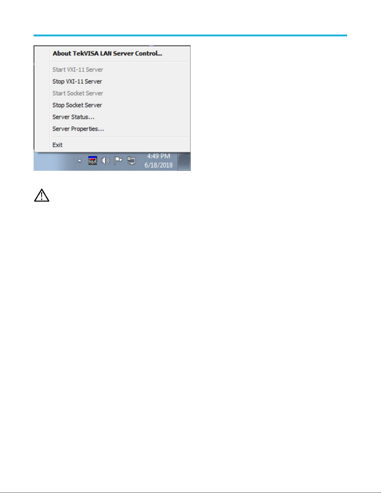
Figure 2: Launch Real-Time Oscilloscope
Note: In the unlikely event when the socket is not initialized, the process can be started by clicking on “Start Socket Server” which
gets enabled during such a scenario.
Operating basics
Launch TekRxService
The TBT3/4 Gen 2 / Gen 3 TekRxTest application interfaces with the oscilloscope for data acquisition, analysis, and data retrieval utilizing
TekRxService application. TekRxService should be launched from the oscilloscope before initiating a connection between the oscilloscope
and TekRxTest application.
Thunderbolt Receiver Test Application Manual 15
Page 16

Application panels
Application panels
Application panels overview
The TBT3/4 Gen 2 / Gen 3 receiver test application uses panels to group the configurations and settings. Click on any panel to configure
the associated settings. A panel may have one or more tabs that lists the selections available in that panel. Controls in a tab may change
depending on the settings made in the same tab or another tab.
Figure 3: Application panels overview
Table 3: Application panels overview
Parameter Description
Connections This panel displays the Real-Time Oscilloscope and Bit Error Rate Tester (BERT) connection settings.
You can connect to a real-time oscilloscope and BERT by entering the IP address of the instruments.
Settings This panel allows configuring various settings for the RT Scope, Analysis Tool, and the Remote Access.
Help This panel displays the application help.
Calibrations This panel allows you to configure the calibration parameters for TP3', TP3, and SFV and save the
results.
Tests This panel allows you to configure the JTOL, Sensitivity, BER, and SFVT test settings and view the
results.
Thunderbolt Receiver Test Application Manual 16
Page 17

Application panels
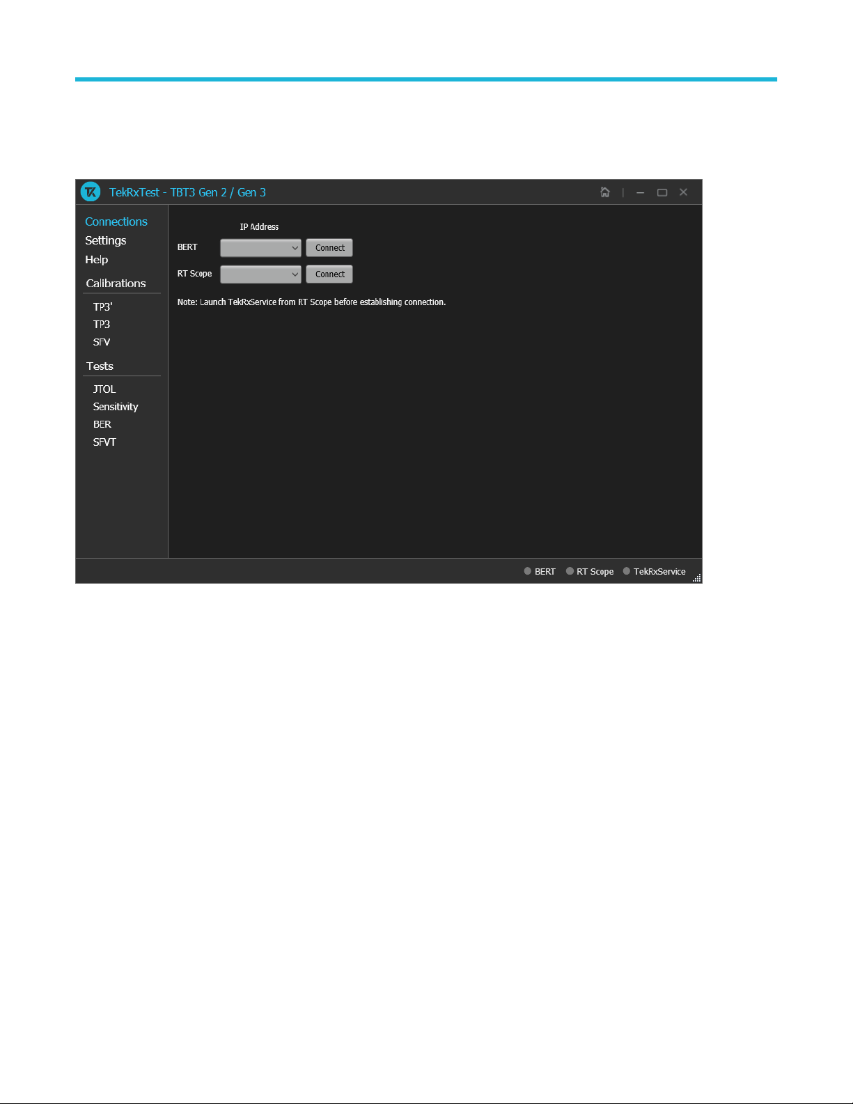
Connections panel
The Connections panel allows you to connect to a real-time oscilloscope and BERT with the TBT3/4 Gen 2 / Gen 3 TekRxTest application.
Enter the IP address of these instruments and click Connect to establish the connection.
Figure 4: Connections panel
Table 4: Connections panel
Connections Description
BERT
RT Scope
Enter the BERT IP address in the address field and click Connect. When the BERT is connected
successfully, the circle next to BERT in the right end corner turns green.
Note: It is recommended to launch the MP1900A software in the administrator mode to use the
TekRxTest Application.
Enter the RT Scope IP address in the address field and click Connect. When the RT Scope is connected
successfully, the circle next to RT Scope and TekRxService in the right end corner turns green.
Note: Before you click Connect, you must launch the TekRxService in the real-time oscilloscope.
Settings panel
The Settings panel allows you to configure the settings for instruments, analysis tool, and remote access. Click on any tab to configure the
associated settings.
Thunderbolt Receiver Test Application Manual 17
Page 18

Application panels
Figure 5: Settings panel
Table 5: Settings panel configurations
Parameter Description
Restore Defaults Restores the application with default settings.
Save Saves the current test setup.
Recall Recalls the saved test setup.
Basic settings
The basic settings display the parameters for RT Scope, Analysis Tool, and Remote access.
Thunderbolt Receiver Test Application Manual 18
Page 19

RT Scope
Application panels
Figure 6: RT Scope
Table 6: RT Scope
Parameter Description
Positive Channel Select the generator data positive channel from BERT.
Negative Channel Select the generator data negative channel from BERT.
Sample Rate Displays the sample rate in GS/s used for the selected channels.
Note: Select appropriate channels (Ch1 and Ch3 or Ch2 and Ch4) which allow 100 GS/s sample rate.
Thunderbolt Receiver Test Application Manual 19
Page 20

Analysis Tool
Application panels
Figure 7: Analysis Tool
Table 7: Analysis Tool
Parameter Description
DPOJET Displays the jitter and eye measurements in TP3' and TP3 calibration.
SigTest
Displays the signal quality measurements captured using a real-time oscilloscope.
You need to provide a valid file path for the TBT3/4 Sigtest executable in the Text box File
Path and the name of the executable in the Text box File Name.
Note: TekRxTest application supports the usage of SigTest Analysis for TP3
Calibration.
Thunderbolt Receiver Test Application Manual 20
Page 21

Remote access
Application panels
Figure 8: Remote access
Table 8: Remote access
Parameter Description
Local IP Address Displays the IP address for connecting to the application over socket server.
Listening Port
Time Out
Displays the TCP/IP port number of the port that the socket server is listening through.
Default Value: 4004
Displays the timeout value used when communicating with the socket server.
Default Value: 20 Seconds
Help panel
The help panel launches the TBT3/4 Gen 2 / Gen 3 TekRxTest application help document.
Calibrations panel
Complete TP3', TP3, and SFV calibrations before you start the DUT testing using the TBT3/4 Gen 2 / Gen 3 TekRxTest application. Follow
the instructions in the calibration wizards to automate the calibration for the TP3' and TP3 calibration points. After calibrating these points,
you can save the results.
Thunderbolt Receiver Test Application Manual 21
Page 22

Application panels
TP3' Calibration
The TP3' calibration panel allows you to perform TP3' calibration for Data Rate and save the results.
You must perform TP3' calibration before you start performing the calibration for TP3.
TP3' Calibration Procedure
Click on TP3' under the Calibrations tab to view the previously run calibration reports. At this stage, you can choose the data rate (10 Gbps
or 10.3125 Gbps or 20 Gbps or 20.625 Gbps), the run calibration reports for the selected data rate will be populated in the results table.
When you click on
procedure to perform the calibration.
During this process, the TekRxTest application calibrates the following items:
1. AC-DC Balance: The subsequent calibration modules assume the high and low frequency portions of the waveform to be of equal
amplitude which is accomplished through AC – DC Balance.
2. Eye Height Calibration: A nominal differential amplitude of 700 mV is calibrated to be used in other calibration modules.
3. Preset Calibration: The various predefined Preshoot and De-emphasis levels are required to be calibrated within a tolerance.
4. DDJ Calibration: The preset with the least data dependent jitter is found and used in further modules.
5. ACCM Calibration: The AC Common Mode Interference is required to be calibrated to 100 mVp-p at a frequency of 400 MHz.
6. RJ Calibration: The Random Jitter is to be calibrated to a nominal value of 0.14 UI p-p.
7. PJ Calibration: The periodic jitter at frequencies of 1, 2, 10, 50 and 100 MHz is calibrated to a nominal value of 0.17 UI p-p.
8. TJ Calibration: The Total Jitter at the predefined frequencies of 1, 2, 10, 50 and 100 MHz is calibrated be in the range of 0.3375 –
0.3625 UI p-p (Gen 2 - 10 and 10.3125 Gbps) and 0.355 – 0.405 UI p-p (Gen 3 - 20 and 20.625 Gbps).
9. Input Eye Diagram: In this step of calibration, it is ensured that the signal, with all the calibrated stresses, meets the Eye Height (700
mV for both Gen2 and Gen3) and Eye Width (0.175-0.825 UI for Gen2 and 0.19-0.81 UI for Gen3) requirements for 1, 2, 10, 50 and
100 MHz with the help of a predefined mask, ensuring that there are no mask hits.
, the TP3' wizard will be launched for the selected generation. This wizard will guide you through the sequential
Thunderbolt Receiver Test Application Manual 22
Page 23

Application panels
Figure 9: TP3' Calibration Panel
1. Connection Diagram: This page displays the connection diagram for the TP3' setup.
Figure 10: TP3' Calibration-Connection Diagram
Thunderbolt Receiver Test Application Manual 23
Page 24

Application panels
Click to move to the next step in the calibration process.
2. Initialization: This page displays the description and allows you to initialize the equipment. Click Initialize Equipment to complete
the initialization process.
You can click Automatic Calibration to perform the automatic calibration with the default settings for amplitude, Tx equalization
presets, ACCM, RJ, and PJ parameters without user intervention.
Figure 11: TP3' Calibration-Initialization
Figure 12: SSC Settings
SSC Settings: You can configure the SSC settings at the beginning of TP3’ calibration.
The profile of the SSC is down spread
Note:
Thunderbolt Receiver Test Application Manual 24
Page 25

Table 9: SSC Settings
Parameter Description
Frequency Enter the frequency in MHz for SSC to be used for all calibration and test modules.
Deviation Enter the deviation in ppm for SSC to be used.
Click to move to the next step in calibration process.
3. AC-DC Balance: This page displays the graph plots of AC-DC balance.
Application panels
Figure 13: TP3' Calibration-AC-DC Balance
Table 10: TP3' Calibration: AC-DC Balance
Parameter Description
Start Click Start to run the measurement.
Cancel Click Cancel to stop the calibration.
Click to move to the next step in calibration process.
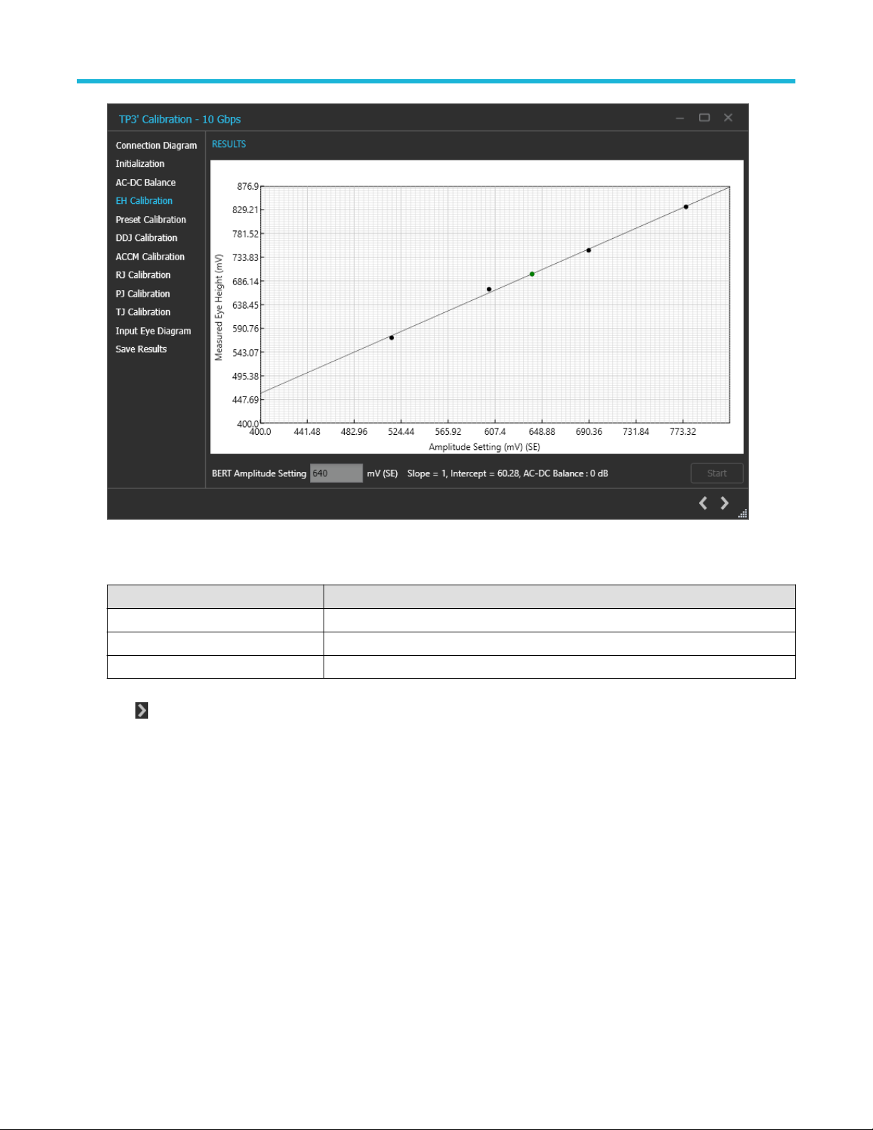
4. EH Calibration: This page displays the graph plots of Eye Height (EH) calibration.
Thunderbolt Receiver Test Application Manual 25
Page 26
Application panels
Figure 14: TP3' Calibration-EH Calibration
Table 11: TP3' Calibration: EH Calibration
Parameter Description
BERT Amplitude Setting Displays the calibrated amplitude corresponding to the nominal Eye Height.
Start Click Start to run the measurement.
Cancel Click Cancel to stop the calibration.
Click to move to the next step in calibration process.
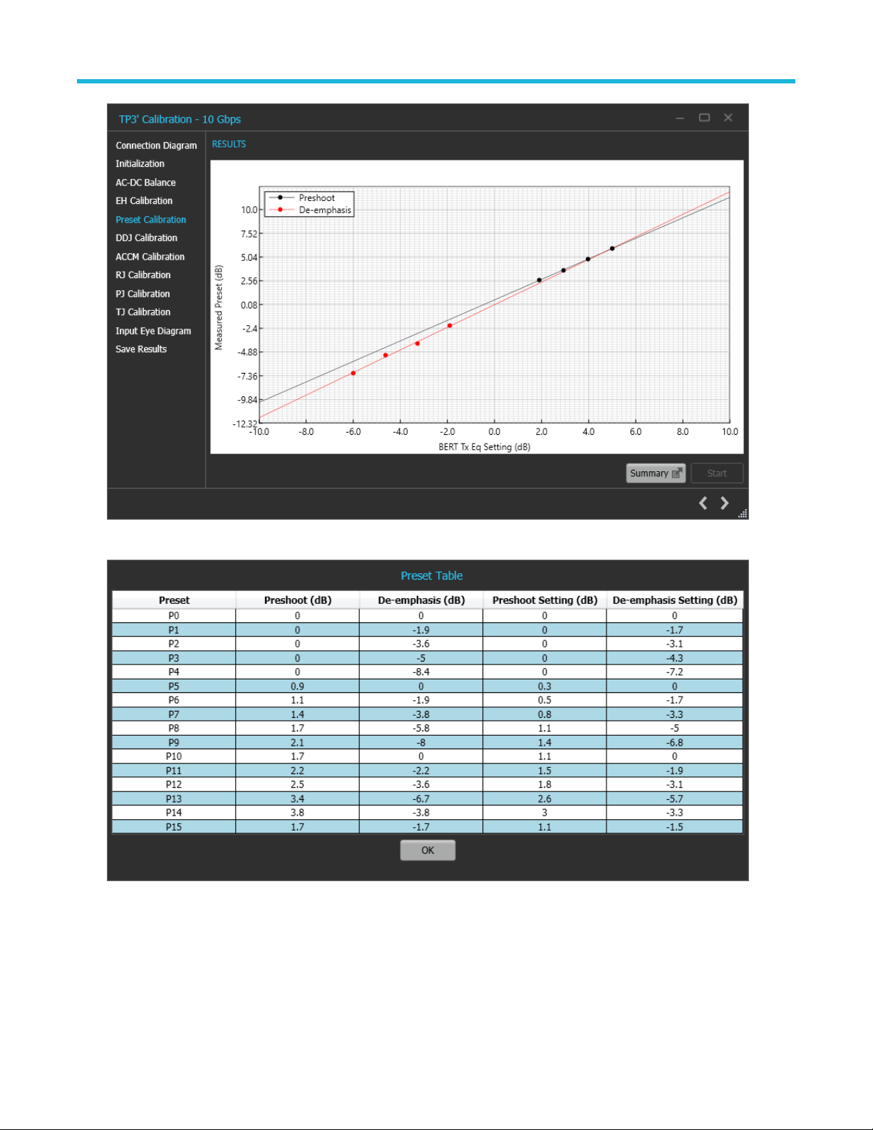
5. Preset Calibration: This page displays the graph plots of preset calibration.
Thunderbolt Receiver Test Application Manual 26
Page 27
Application panels
Figure 15: TP3' Calibration-Preset Calibration
Figure 16: TP3' Calibration-Preset Calibration-Table
Thunderbolt Receiver Test Application Manual 27
Page 28
Application panels
Table 12: TP3' Calibration: Preset Calibration
Parameter Description
Summary Displays the summarized results for Preshoot and De-emphasis setting on the BERT for
the predefined preset levels.
Start Click Start to run the measurement.
Cancel Click Cancel to stop the calibration.
Click to move to the next step in calibration process.
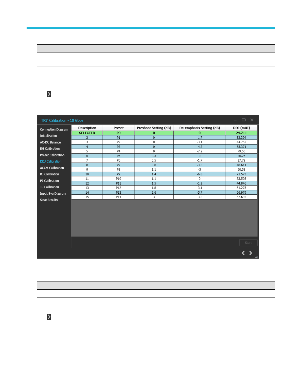
6. DDJ Calibration: This page displays a summarized table for the data dependent jitter calculated for the calibrated preshoot and
de-emphasis values set on the BERT.
Figure 17: TP3' Calibration-DDJ Calibration
Table 13: TP3' Calibration: DDJ Calibration
Parameter Description
Start Click Start to run the measurement.
Cancel Click Cancel to stop the calibration.
Click to move to the next step in calibration process.
7. ACCM Calibration: This page displays the graph plot for ACCM calibration.
Thunderbolt Receiver Test Application Manual 28
Page 29

Application panels
Figure 18: TP3' Calibration-ACCM Calibration
Table 14: TP3' Calibration: ACCM Calibration
Parameter Description
ACCM Setting Displays the calibrated ACCM value corresponding to the nominal value.
Start Click Start to run the measurement.
Cancel Click Cancel to stop the calibration.
Click to move to the next step in calibration process.
8. RJ Calibration: This page displays the graph plot for RJ calibration.
Thunderbolt Receiver Test Application Manual 29
Page 30

Application panels
Figure 19: TP3' Calibration-RJ Calibration
Table 15: TP3' Calibration: RJ Calibration
Parameter Description
RJ Setting Displays the calibrated RJ value corresponding to the nominal value.
Start Click Start to run the measurement.
Cancel Click Cancel to stop the calibration.
Click to move to the next step in calibration process.
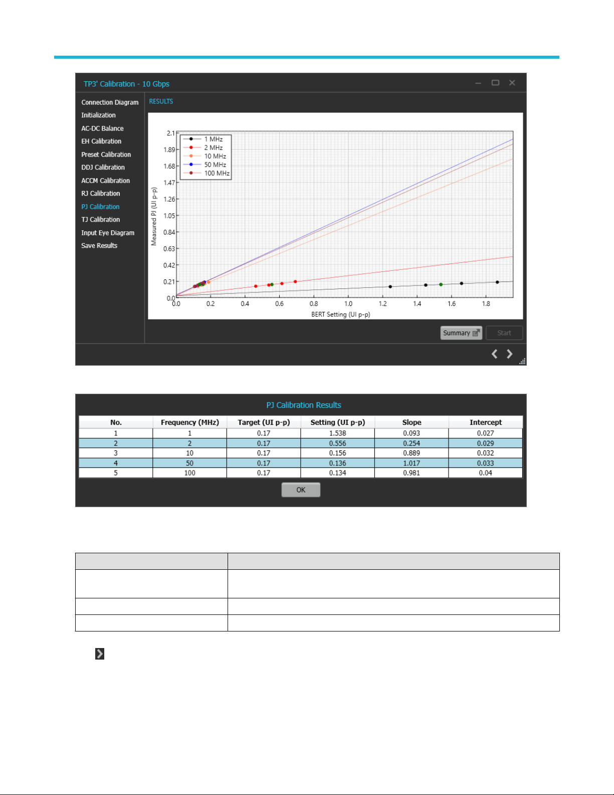
9. PJ Calibration: This page displays the graph plots for PJ calibration for the frequencies of 1, 2, 10, 50 and 100 MHz.
Thunderbolt Receiver Test Application Manual 30
Page 31
Application panels
Figure 20: TP3' Calibration-PJ Calibration
Figure 21: TP3' Calibration-PJ Calibration-Summary
Table 16: TP3' Calibration: PJ Calibration
Parameter Description
Summary Displays a summary of the calibrated PJ value corresponding to the nominal value for the
frequencies of 1, 2, 10, 50 and 100 MHz.
Start Click Start to run the measurement.
Cancel Click Cancel to stop the calibration.
Click to move to the next step in calibration process.
10. TJ Calibration: This page displays a table for the RJ and PJ value set on the BERT for the random and periodic jitter and the total
jitter corresponding to that combination for the frequencies of 1, 2, 10, 50 and 100 MHz.
Thunderbolt Receiver Test Application Manual 31
Page 32

Application panels
Figure 22: TP3' Calibration-TJ Calibration
Figure 23: TP3' Calibration-TJ Calibration-Summary
Table 17: TP3' Calibration: TJ Calibration
Parameter Description
TJ Range Displays the TJ range in UI p-p.
Note: TJ range for Gen 2: 0.3375 - 0.3625 UI p-p.
TJ range for Gen 3: 0.355 - 0.405 UIp-p.
Selected Preset Displays the preset with the lowest DDJ used to calibrate TJ.
Summary Displays a summarized table for the combination of RJ and PJ where the TJ is in range
for a given frequency.
Start Click Start to run the measurement.
Cancel Click Cancel to stop the calibration.
Thunderbolt Receiver Test Application Manual 32
Page 33

Application panels
Click to move to the next step in calibration process.
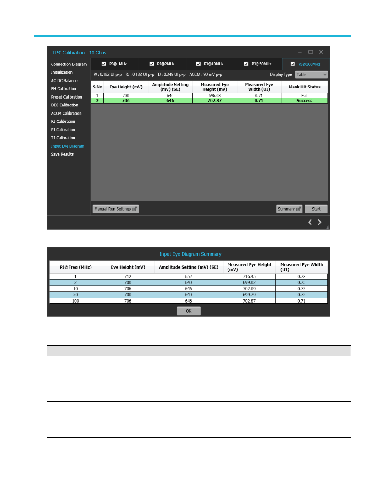
11. Input Eye Diagram: This page displays the combination of stresses and amplitude and the measured Eye Height, Eye Width and
the Mask Hit Status in a tabular format.
Figure 24: TP3' Calibration-Input Eye Diagram-Eye Diagram
Thunderbolt Receiver Test Application Manual 33
Page 34
Application panels
Figure 25: TP3' Calibration-Input Eye Diagram-Table
Figure 26: TP3' Calibration-Input Eye Diagram-Summary
Table 18: TP3' Calibration: Input Eye Diagram
Parameter Description
Display Type Select the required display type form the drop down list.
Table: Showcases the amplitude and stresses set on the BERT and the corresponding
Eye Height, Eye Width and the Mask Hit Status with respect to a predefined mask.
Eye Diagram: Shows the real time eye measurements against the predefined mask.
Summary Displays a summarized table for the Eye Height, Amplitude Setting, Measured Eye
Height, and Measured Eye Width for which a successful mask hit status has been
achieved for the run frequencies.
Start Click Start to run the measurement.
Table continued…
Thunderbolt Receiver Test Application Manual 34
Page 35

Parameter Description
Cancel Click Cancel to stop the calibration.
Manual Run Settings
Eye Height Displays the Eye Height value for the selected PJ frequency.
Start Click Start to initiate the manual run with the given the Eye Height
Click to move to the next step in calibration process.
12. Save Results: This page allows you to save the TP3' calibration results.
Application panels
Figure 27: TP3' Calibration-Save Results
Table 19: TP3' Calibration: Save Results
Parameter Description
Unique ID Enter the Unique ID of the calibrated equipment in the text box.
Generated By Enter the user name in the text box.
Comments Enter the required comments in the comment box (Optional).
Save Click to save the results.
Click to complete the TP3' calibration and close the wizard.
Upon completion of the TP3' calibration process or in the event of cancellation of the process, the BERT data
Note:
generator will be turned off automatically by the TBT3/4 Gen 2 / Gen 3 TekRxTest application.
Thunderbolt Receiver Test Application Manual 35
Page 36

Application panels
TP3 Calibration
The TP3 Calibration panel allows you to perform calibration at the TP3 endpoint for Data Rate and save the results.
TP3 Calibration Procedure
Click on TP3 under the Calibrations tab to view the previously run calibration reports. At this stage, you can choose the data rate (10 Gbps
or 10.3125 Gbps or 20 Gbps or 20.625 Gbps), the run calibration reports for the selected data rate will be populated in the results table.
When you click on , the TP3 wizard will be launched for the selected generation. This wizard will guide you through the sequential
procedure to perform the calibration.
During this process, the TekRxTest application calibrates the following items:
1. Insertion Loss: In this step, the channel loss between the BERT and Receptacle Fixture-2 is computed to be within the range of 18-19
dB (Gen 2) and 16-17 dB (Gen 3). The right ISI pair needs to be connected along with de-embedding the loss incurred for the phase
matched cables to get the loss in the specified range.
2. CTLE Selection: The process is carried out for the frequencies of 1, 2, 10, 50 and 100 MHz where the user can choose between the
CTLE indices (CTLE 0-9) and preset to be used. The optimum CTLE is chosen to give the maximum eye area. The user needs to take
note that the choice of CTLE indices and number of acquisitions is only available when the configured Analysis Tool is DPOJET.
3. Stressed Eye: In the case where CTLE selection provides the eye parameters to be in range, this step can be skipped. As a part of
this method, the jitter (Random Jitter for frequencies of 1, 2, 10 and 50 MHz and Periodic Jitter for 100 MHz), and amplitude are swept
to attain the Eye Width of 0.555-0.605 UI (Gen 2 - Rounded and Legacy) or 0.49-0.59 UI (Gen 3 - Rounded and Legacy) and an Eye
Height of 110-130 mV (Gen 2 - Rounded and Legacy) or 88-108 mV (Gen 3 - Rounded and Legacy).
Figure 28: TP3 Calibration Panel
1. Connection Diagram: This page displays the connection diagram for the TP3 setup.
Thunderbolt Receiver Test Application Manual 36
Page 37

Application panels
Figure 29: TP3 Calibration-Connection Diagram
Click to move to the next step in calibration process.
2. Calibration Selection: This page allows you to select a completed TP3 Calibration file from the drop-down list. Click Initialize
Equipment to complete the initialization process.
Thunderbolt Receiver Test Application Manual 37
Page 38

Application panels
Figure 30: TP3 Calibration-Calibration Selection
You can click Automatic Calibration to perform the automatic calibration with the default settings without user intervention.
Click on Configuration to add de-embedding filter files for positive and negative channels. You can enter the manual loss, if already
known.
Thunderbolt Receiver Test Application Manual 38
Page 39

Application panels
Figure 31: TP3 Calibration-Configuration Settings
Click to move to the next step in calibration process.
3. Insertion Loss: This page displays the automated procedure to compute the channel loss from the BERT to receptacle fixture-2. The
user can also enter the loss value in the Manual Loss section if the loss in the channel is already known, skipping this step altogether.
Thunderbolt Receiver Test Application Manual 39
Page 40

Application panels
Figure 32: TP3 Calibration-Insertion Loss
Table 20: TP3 Calibration: Insertion Loss
Parameter Description
Manual Loss Allows user to enter the manual loss if already known. This field updates with the loss
value once the loss in the given setup is computed.
# Scope acqs Allows user to enter the number of acquisitions in a single waveform.
# Acqs Allows user to enter the number of waveforms acquired for averaging before passing for
analysis.
Start Click Start to run the measurement.
Cancel Click Cancel to stop the calibration.
Click to move to the next step in calibration process.
4. CTLE Selection: This page displays the CTLE selection for each PJ frequency.
Thunderbolt Receiver Test Application Manual 40
Page 41

Application panels
Figure 33: TP3 Calibration-CTLE Selection
Figure 34: CTLE Selection-Summary
Table 21: TP3 Calibration: CTLE Selection
Parameter Description
Configuration Allows the user to select the (For DPOJET) and Preset (For SigTest) to be used during the
procedure.
Summary Displays a summarized table of the Selected Preset, Selected CTLE, Measured Eye
Height, Measured Eye Width, and Eye Area.
Start Click Start to run the measurement.
Cancel Click Cancel to stop the calibration.
Click to move to the next step in calibration process.
Thunderbolt Receiver Test Application Manual 41
Page 42

Application panels
5. Stressed Eye: This page displays the stresses, amplitude, CTLE index and preset applied on the BERT to get the measured Eye
Height and Eye Width for the PJ frequencies of 1,2, 10, 50 and 100 MHz.
Figure 35: TP3 Calibration-Stressed Eye-Eye Diagram
Thunderbolt Receiver Test Application Manual 42
Page 43

Application panels
Figure 36: TP3 Calibration-Stressed Eye-Table
Figure 37: TP3 Calibration-Stressed Eye-Calibration Summary
Table 22: TP3 Calibration: Stressed Eye
Parameter Description
Display Type Select the required display type form the drop down list.
Table: Showcases the amplitude and stresses set on the BERT and the corresponding Eye
Height, Eye Width.
Eye Diagram: Shows the real time eye diagram for the set stresses and amplitude.
Summary Displays a summarized version of the stresses, amplitude, measured Eye Height and
Measured Eye Width for the run frequencies.
Start Click Start to run the measurement.
Table continued…
Thunderbolt Receiver Test Application Manual 43
Page 44

Application panels
Parameter Description
Manual Run Settings
Eye Height Allows the user to configure the eye height for the selected PJ frequency.
RJ/PJ Allows you to configure the RJ value for PJ frequencies of 1,2,10 and 50 MHz and PJ
value for PJ frequency of 100 MHz.
Start Click Start to run an instance with the configured manual settings.
Click to move to the next step in calibration process.
6. Save Results: This page allows you to save the TP3 calibration results.
Figure 38: TP3 Calibration-Save Results
Table 23: TP3 Calibration: Save Results
Parameter Description
Unique ID Enter the Unique ID of the calibrated equipment in the text box.
Generated By Enter the user name in the text box.
Comments Enter the required comments in the comment box (Optional).
Save Click to save the results.
Click to complete the TP3 calibration and close the wizard.
Upon completion of the TP3 calibration process or in the event of cancellation of the process, the BERT data generator
Note:
will be turned off automatically by the TBT3/4 Gen 2 / Gen 3 TekRxTest application.
Thunderbolt Receiver Test Application Manual 44
Page 45

Application panels
SFV Calibration
The SFV Calibration Panel allows you to perform Signal Frequency Variations Calibration at the calibration points of TP3’ and TP3 for
Gen2 and Gen3 and save the results.
You must perform calibration for the chosen calibration point before performing the SFV calibration.
SFV Calibration Procedure
Click on SFV under the Calibrations tab to view the previously run calibration reports. At this stage, you can select the generation (10,
10.3125, 20, and 20.625 Gbps) and then run the calibration reports for the chosen generation, which then appear in the results table.
When you click on
perform the calibration.
During this process, the TekRx Test application calibrates the SSC parameters of Initial Frequency, Frequency Overshoot, Delta Frequency
200ns, and Delta Frequency 1000ns.
1. Calibration Selection: This page allows you to choose the calibration point at which the Signal Frequency Variations should be
performed. All the completed calibration files for the selected calibration point can be found by clicking on the drop-down menu.
, the SFV wizard opens for the selected data rate. This wizard guides you through the sequential procedure to
Figure 39: SFV Calibration-Calibration Selection
Click to move to the next step in the calibration process.
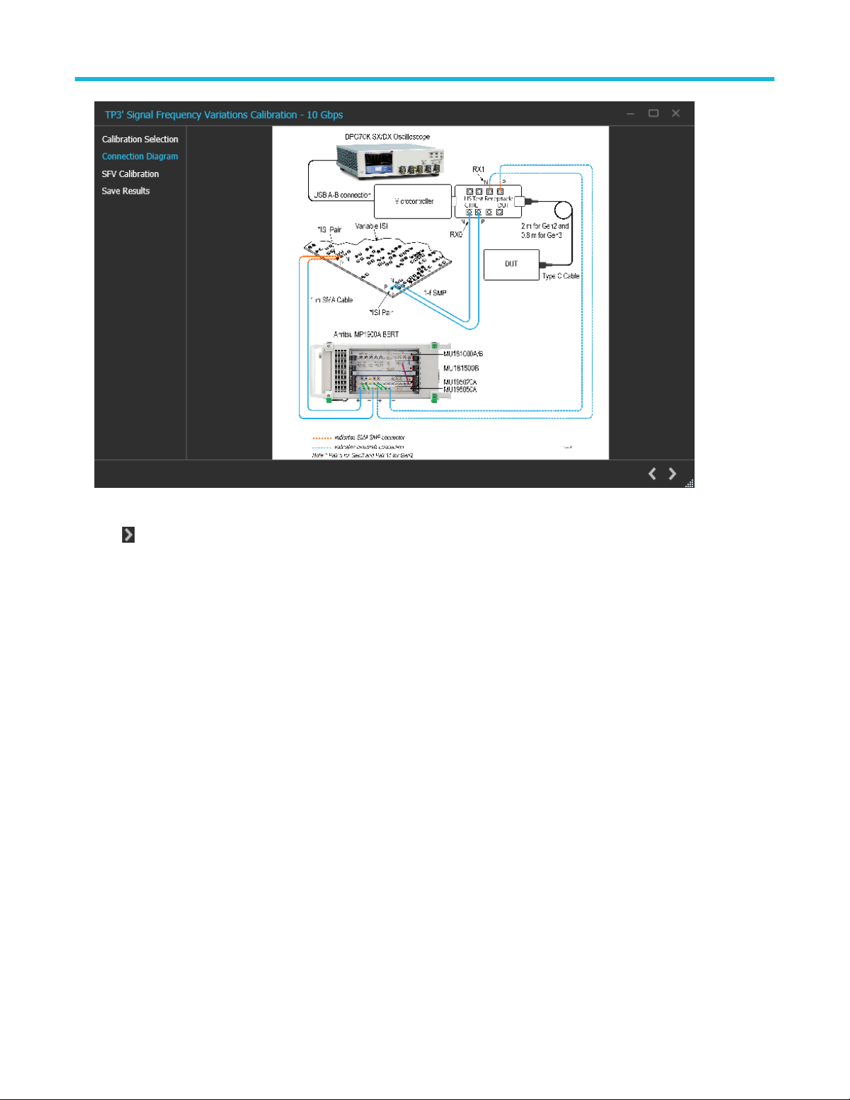
2. Connection Diagram: This page displays the connection diagram for the SFV calibration based on the selection made on the previous
page.
Thunderbolt Receiver Test Application Manual 45
Page 46
Application panels
Figure 40: SFV Calibration-Connection Diagram
Click to move to the next step in the calibration process.
3. SFV Calibration: This page displays tabular data for the SSC parameters set on the BERT and their respective measured values for
the PJ@100MHz. Once the parameters are in the range, as indicated in the lower section, the calibration is complete and the row is
highlighted.
Thunderbolt Receiver Test Application Manual 46
Page 47

Application panels
Figure 41: SFV Calibration
Click to move to the next step in the calibration process.
4. Save Results: This page allows you to save the SFV calibration results.
Figure 42: SFV Calibration-Save Results
Thunderbolt Receiver Test Application Manual 47
Page 48

Application panels
Table 24: SFV Calibration: Save Results
Parameter Description
Unique ID Enter the Unique ID of the calibrated equipment in the text box.
Generated By Enter the user name in the text box.
Comments Enter the required comments in the comment box (Optional).
Save Click to save the results.
Click to complete the SFV and close the wizard.
Note: Upon completion or cancellation of the SFV calibration process, the BERT data generator is automatically turned off by
theTBT3/4 Gen 2 / Gen 3 (Legacy and Rounded) TekRxTest application.
Tests panel
JTOL Test
To test the DUT error tolerance for PJ at frequencies of 1, 2, 10, 50 and 100 MHz, you can choose either TP3' (Case 1) or TP3 (Case 2) as
test points. You can sweep the PJ amplitude for the frequencies and find the threshold point of the DUT.
The stresses used are loaded from the chosen calibration file (TP3' or TP3). If the selected frequency was not calibrated for, then the
nearest calibrated frequency data will be used for running the JTOL test.
JTOL Test procedure
Click on JTOL under the Tests tab to view the previously completed results. At this stage, you can choose the data rate for which the DUT
tolerance needs to be performed. Upon clicking a data rate, all the previously completed results for that data rate get populated in the
results table. Click on
sequential procedure to perform the test.
1. Calibration Selection: This page allows to select the test point at which the tolerance test needs to be performed. You can find all the
completed calibration files for the selected test point by clicking on the drop-down.
at the right end corner of the application to launch the JTOL test wizard. The wizard will guide you through the
Thunderbolt Receiver Test Application Manual 48
Page 49

Application panels
Figure 43: JTOL Test-Calibration Selection
Click to move to the next step in test process.
2. Connection Diagram: This page displays the connection diagram for the JTOL test for the selected test point in the previous page.
Thunderbolt Receiver Test Application Manual 49
Page 50

Application panels
Figure 44: JTOL Test-Connection Diagram
Click to move to the next step in test process.
3. Configure Test: This page allows you to configure the test settings.
Thunderbolt Receiver Test Application Manual 50
Page 51

Application panels
Figure 45: JTOL Test-Configure Test
Thunderbolt Receiver Test Application Manual 51
Page 52

Application panels
Table 25: JTOL Test: Configure Test
Parameter Description
Stress Configuration Displays the calibrated stress parameters for the frequencies 1, 2, 10, 50 and 100
MHz.
You can configure the stress parameters for each frequency using the following
options:
• Calibrated
• Customized
• Un-Calibrated
Note: If a particular frequency was not calibrated for in the chosen
calibration file, the stress parameters showcased are that of the nearest
calibrated frequency.
ACCM Displays the calibrated ACCM value in mVp-p / For Un-Calibrated and Customized
selections, enter the desired ACCM value to be used in the test.
RJ Displays the calibrated RJ value in UIp-p / For Un-Calibrated and Customized
selections, enter the desired RJ value to be used in the test.
Amplitude For Un-Calibrated amplitude value in mV(SE), enter the desired amplitude value to be
used in the test.
Eye Height Displays the calibrated Eye Height in mV.
PJ Displays the calibrated PJ value in UIp-p.
SSC Click the check box to enable SSC during the test.
Frequency Displays the SSC frequency configured during calibration.
Deviation Displays the SSC deviation configured during calibration.
BER Measurement Pattern Select the required BER measurement pattern from the drop-down list.
Logic Select the polarity or logic for the selected BER Measurement pattern from the
drop-down list.
BERT Preset Selection
Initial Preset Select the preset to be set on the BERT PPG right before Preset Negotiation from the
drop-down list.
Preshoot Displays the Preshoot corresponding to the selected Initial Preset.
De-emphasis Displays the De-emphasis corresponding to the selected Initial Preset.
Crosstalk
Near-end If checked, the DUT produces crosstalk internally while running the test.
Far-end If checked, you can select the source of the far-end crosstalk.
Data2: The BERT Data2 acts as a source of far-end crosstalk, you can configure the
amplitude of the aggressor signal in this case.
Other Sources: You can use any other external device to provide far-end crosstalk.
Click to move to the next step in test process.
4. Configure JTOL Test: This page allows you to configure the JTOL test settings.
Thunderbolt Receiver Test Application Manual 52
Page 53

Application panels
Figure 46: JTOL Test-Configure JTOL Test
Table 26: JTOL Test: Configure JTOL Test
Parameter Description
Frequency Settings
PJ@Freq (MHz) Displays the list of frequencies in MHz for which JTOL test is to be performed.
Lower Amplitude Limit (UI p-p) Enter the lower amplitude limit of PJ at which JTOL test will start for the
corresponding frequency.
Higher Amplitude Limit (UI p-p) Enter the higher amplitude limit of PJ at which JTOL test will end for the
corresponding frequency.
Default Click to view the table populated with default amplitude limits for the frequencies 1, 2,
10, 50 and 100 MHz.
Custom Mask Define the PJ amplitude values for the frequencies 1, 2, 10, 50 and 100 MHz. Upon
enabling the JTOL Custom Mask, the configured mask will be generated on the plot.
PJ@Freq (MHz) Displays the table of frequencies for the mask.
Amplitude (UI p-p) Enter the amplitude of PJ at each frequency.
Upward Search Select the required search algorithm from the drop-down for JTOL test.
# Points Enter the number of points between the lower and higher amp limit in case of Linear
and Log search.
ETT Configuration
Tested Port Configure the port to run JTOL test on for the ETT tool (0 - 63).
Table continued…
Thunderbolt Receiver Test Application Manual 53
Page 54

Application panels
Parameter Description
Test Duration Configure the test duration in seconds.
Note: The default test duration for Gen 2 (Rounded and Legacy) and Gen 3
(Rounded and Legacy) is 400s and 200s respectively.
Link Select the required link for ETT tool (Single Lane or Dual Lane).
DUT Type Select the DUT type used during the test from the drop-down list.
Tested Lane Select the lane on which the JTOL test will run.
Swap Lane Select the required swap lane for ETT tool.
Exe Path Enter the path for the ETT tool executable file in the RT Scope.
TigerLake Enable if the DUT you are testing is a TigerLake device.
Click to move to the next step in test process.
5. Run Test: This page displays a graphical representation of JTOL test result. It includes the result table tab which displays the JTOL
test results in a tabular form.
Figure 47: JTOL Test-Run Test
Table 27: JTOL Test: Run Test
Parameter Description
Start Click Start to initiate the test.
Cancel Click Cancel to stop the test.
Thunderbolt Receiver Test Application Manual 54
Page 55

Click to move to the next step in test process.
6. Save Results: This page allows you to save the JTOL test results.
Application panels
Figure 48: JTOL Test-Save Results
Table 28: JTOL Test: Save Results
Parameter Description
Unique ID Enter the Unique ID of the calibrated equipment in the text box.
Generated By Enter the user name in the text box.
Comments Enter the required comments in the comment box (Optional).
Save Click to save the results.
Click to complete the JTOL Test and close the wizard.
Sensitivity Test
To test the DUT error tolerance for Eye Height at frequencies of 1, 2, 10, 50 and 100 MHz, you can choose either TP3' (Case 1) or TP3
(Case 2) as test points. You can sweep the amplitude for the given frequencies and find the tolerance of the DUT.
The stresses used are loaded from the chosen calibration file (TP3' or TP3). If the selected frequency was not calibrated for, then the
nearest calibrated frequency data will be used for running the Sensitivity test.
Sensitivity Test procedure
Click on Sensitivity under the Tests tab to view the previously completed results. At this stage, you can choose the data rate for which the
DUT tolerance test needs to be performed. Upon clicking a data rate, all the previously completed results for that data rate get populated
Thunderbolt Receiver Test Application Manual 55
Page 56

Application panels
in the results table. Click on at the right end corner of the application to launch the Sensitivity test wizard. The wizard will guide you
through the sequential procedure to perform the test.
1. Calibration Selection: This page allows to select the test point at which the tolerance test needs to be performed. You can find all the
completed calibration files for the selected test point by clicking on the drop-down.
Figure 49: Sensitivity Test-Calibration Selection
Click to move to the next step in test process.
2. Connection Diagram: This page displays the connection diagram for the Sensitivity test for the chosen test point in the previous page.
Thunderbolt Receiver Test Application Manual 56
Page 57

Application panels
Figure 50: Sensitivity Test-Connection Diagram
Click to move to the next step in test process.
3. Configure Test: This tab allows you to configure the test settings.
Thunderbolt Receiver Test Application Manual 57
Page 58

Application panels
Figure 51: Sensitivity Test-Configure Test
Thunderbolt Receiver Test Application Manual 58
Page 59

Application panels
Table 29: Sensitivity Test: Configure Test
Parameter Description
Stress Configuration Displays the calibrated stress parameters for the frequencies 1, 2, 10, 50 and 100
MHz.
You can configure the stress parameters for each frequency using the following
options:
• Calibrated
• Customized
• Un-Calibrated
Note: If a particular frequency was not calibrated for in the chosen
calibration file, the stress parameters showcased are that of the nearest
calibrated frequency.
ACCM Displays the calibrated ACCM value in mVp-p / For Un-Calibrated and Customized
selections, enter the desired ACCM value to be used in the test.
RJ Displays the calibrated RJ value in UIp-p / For Un-Calibrated and Customized
selections, enter the desired RJ value to be used in the test.
Amplitude For Un-Calibrated amplitude value in mV(SE), enter the desired amplitude value to be
used in the test.
Eye Height Displays the calibrated Eye Height in mV.
PJ Displays the calibrated PJ value in UIp-p.
SSC Click the check box to enable SSC during the test.
Frequency Displays the SSC frequency configured during calibration.
Deviation Displays the SSC deviation configured during calibration.
BER Measurement Pattern Select the required BER measurement pattern from the drop-down list.
Logic Select the polarity or logic for the selected BER Measurement pattern from the
drop-down list.
BERT Preset Selection
Initial Preset Select the preset to be set on the BERT PPG right before Preset Negotiation from the
drop-down list.
Preshoot Displays the Preshoot corresponding to the selected Initial Preset.
De-emphasis Displays the De-emphasis corresponding to the selected Initial Preset.
Crosstalk
Near-end If checked, the DUT produces crosstalk internally while running the test.
Far-end If checked, you can select the source of the far-end crosstalk.
Data2: The BERT Data2 acts as a source of far-end crosstalk, you can configure the
amplitude of the aggressor signal in this case.
Other Sources: You can use any other external device to provide far-end crosstalk.
Click to move to the next step in test process.
4. Configure Sensitivity Test: This page allows you to configure the sensitivity test settings.
Thunderbolt Receiver Test Application Manual 59
Page 60

Application panels
Figure 52: Sensitivity Test-Configure Sensitivity Test
Table 30: Sensitivity Test: Configure Sensitivity Test
Parameter Description
Amplitude Limit Settings
PJ@Freq (MHz) Displays the list of frequencies in MHz for which Sensitivity test is to be performed.
Lower Amplitude Limit (UI p-p) Enter the lower amplitude limit of PJ at which Sensitivity test will end for the
corresponding frequency.
Higher Amplitude Limit (UI p-p) Enter the higher amplitude limit of PJ at which Sensitivity test will start for the
corresponding frequency.
Default Click to view the table populated with default amplitude limits for the frequencies 1, 2,
10, 50 and 100 MHz.
Custom Mask Define the PJ amplitude values for the frequencies 1, 2, 10, 50 and 100 MHz. Upon
enabling the Sensitivity Custom Mask, the configured mask will be generated on the
plot.
PJ@Freq (MHz) Displays the table of frequencies for the mask.
Eye Height Enter the amplitude of PJ at each frequency.
Downward Search Select the required search algorithm from the drop-down for JTOL test.
# Points Enter the number of points between the lower and higher amp limit in case of Linear
and Log search.
ETT Configuration
Tested Port Configure the port to run Sensitivity test on for the ETT tool (0 - 63).
Table continued…
Thunderbolt Receiver Test Application Manual 60
Page 61

Application panels
Parameter Description
Test Duration Configure the test duration in seconds.
Note: The default test duration for Gen 2 and Gen 3 is 400s and 200s
respectively.
Link Select the required link for ETT tool (Single Lane or Dual Lane).
DUT Type Select the DUT type used during the test from the drop-down list.
Tested Lane Select the lane on which the Sensitivity test will run.
Swap Lane Select the required swap lane for ETT tool.
Exe Path Enter the path for the ETT tool executable file in the RT Scope.
TigerLake Enable if the DUT you are testing is a TigerLake device.
Click to move to the next step in test process.
5. Run Test: This page displays a graphical representation of the Sensitivity Test result. It includes the result table tab which displays the
sensitivity test results in a tabular form.
Figure 53: Sensitivity Test-Run Test
Table 31: Sensitivity Test: Run Test
Parameter Description
Start Click Start to initiate the test.
Cancel Click Cancel to stop the test
Thunderbolt Receiver Test Application Manual 61
Page 62

Click to move to the next step in test process.
6. Save Results: This page allows you to save the sensitivity test results.
Application panels
Figure 54: Sensitivity Test-Save Results
Table 32: Sensitivity Test: Save Results
Parameter Description
Unique ID Enter the Unique ID of the calibrated equipment in the text box.
Generated By Enter the user name in the text box.
Comments Enter the required comments in the comment box (Optional).
Save Click to save the results.
Click to complete the Sensitivity Test and close the wizard.
BER Test
To find the DUT Bit Error Rate for the defined duration (400 sec in Gen 2 and 200 sec in Gen 3) using the stress conditions calibrated
during TP3' (Case 1) or TP3 (Case 2).
BER Test procedure
Click on BER under the Tests tab to view the measurement results. At this stage, you can choose the data rate for which the DUT BER test
needs to be performed. Upon clicking a data rate, all the measurement results for that data rate get populated in the results table. Click on
at the right end corner of the application to launch the BER test wizard. The wizard will guide you through the sequential procedure to
perform the test.
Thunderbolt Receiver Test Application Manual 62
Page 63

Application panels
1. Calibration Selection: This page allows to select the test point at which the BER test needs to be performed. You can find all the
completed calibration files for the selected test point by clicking on the drop-down.
Figure 55: BER Test-Calibration Selection
Click to move to the next step in test process.
2. Connection Diagram: This page displays the connection diagram for BER test for the selected test point in the previous page.
Thunderbolt Receiver Test Application Manual 63
Page 64

Application panels
Figure 56: BER Test-Connection Diagram
Click to move to the next step in test process.
3. Configure Test: This page allows you to configure the test settings.
Thunderbolt Receiver Test Application Manual 64
Page 65

Application panels
Figure 57: BER Test-Configure Test
Table 33: BER Test: Configure Test
Parameter Description
Stress Configuration Displays the calibrated stress parameters for the frequencies 1, 2, 10, 50 and 100
MHz.
You can configure the stress parameters for each frequency using the following
options:
• Calibrated
• Customized
• Un-Calibrated
Note: If a particular frequency was not calibrated for in the chosen
calibration file, the stress parameters showcased are that of the nearest
calibrated frequency.
ACCM Displays the calibrated ACCM value in mVp-p / For Un-Calibrated and Customized
selections, enter the desired ACCM value to be used in the test.
Table continued…
Thunderbolt Receiver Test Application Manual 65
Page 66

Application panels
Parameter Description
RJ Displays the calibrated RJ value in UIp-p / For Un-Calibrated and Customized
selections, enter the desired RJ value to be used in the test.
Amplitude For Un-Calibrated amplitude value in mV(SE), enter the desired amplitude value to be
used in the test.
Eye Height Displays the calibrated Eye Height in mV.
PJ Displays the calibrated PJ value in UIp-p.
SSC Click the check box to enable SSC during the test.
Frequency Displays the SSC frequency configured during calibration.
Deviation Displays the SSC deviation configured during calibration.
BER Measurement Pattern Select the required BER measurement pattern from the drop-down list.
Logic Select the polarity or logic for the selected BER Measurement pattern from the
drop-down list.
BERT Preset Selection
Initial Preset Select the preset to be set on the BERT PPG right before Preset Negotiation from the
drop-down list.
Preshoot Displays the Preshoot corresponding to the selected Initial Preset.
De-emphasis Displays the De-emphasis corresponding to the selected Initial Preset.
Crosstalk
Near-end If checked, the DUT produces crosstalk internally while running the test.
Click to move to the next step in test process.
4. Configure BER Test: This page allows you to configure the BER test settings.
Thunderbolt Receiver Test Application Manual 66
Page 67

Application panels
Figure 58: BER Test-Configure BER Test
Table 34: BER Test: Configure BER Test
Parameter Description
ETT Configuration
Tested Port Configure the port to run BER test on for the ETT tool (0 - 63).
Test Duration Configure the test duration in seconds.
Note: The default test duration for Gen 2 and Gen 3 is 400s and 200s
respectively.
Link Select the required link for ETT tool (Single Lane or Dual Lane).
DUT Type Select the DUT type used during the test from the drop-down list.
Tested Lane Select the lane on which the BER test will run.
Swap Lane Select the required swap lane for ETT tool.
Exe Path Enter the path for the ETT tool executable file in the RT Scope.
TigerLake Enable if the DUT you are testing is a TigerLake device.
Click to move to the next step in test process.
5. BER Test: This page displays a tabular representation of the BER test result. The table gets populated in real time as the test runs for
the selected frequencies.
Thunderbolt Receiver Test Application Manual 67
Page 68

Application panels
Figure 59: BER Test-Run Test
Table 35: BER Test: Run Test
Parameter Description
Presets (Intermediate) Updates the last preset from the preset negotiation between DUT and BERT.
#Errors (Intermediate) Updates the errors after running BER test for 10 seconds after each preset negotiation.
Preset (Negotiation) Updates the last preset from the preset negotiation before running the BER test for 200s
(Gen 3) or 400s (Gen 2).
#Errors Updates the number of errors after the test has completed.
BER Updates the BER value after the test has completed.
Status Updates the Pass/Fail after test completion.
Start Click Start to run the measurement.
Cancel Click Cancel to stop the test.
Click to move to the next step in test process.
6. Save Results: This page allows you to save the BER test results.
Thunderbolt Receiver Test Application Manual 68
Page 69

Application panels
Figure 60: BER Test-Save Results
Table 36: BER Test: Save Results
Parameter Description
Unique ID Enter the Unique ID of the calibrated equipment in the text box.
Generated By Enter the user name in the text box.
Comments Enter the required comments in the comment box (Optional).
Save Click to save the results.
Click to complete the BER Test and close the wizard.
SFVT Test
To test the DUT error tolerance upon frequency variation at PJ@100MHz. You can perform the test at the TP3’ (Case1) or TP3 (Case 2)
test point at which the SFV calibration has already been performed. The stresses calibrated for PJ@100MHz in the chosen calibration file
are used while performing the SFVT test.
SFVT Test procedure
Click on SFVT under the Tests tab to view the test results. At this stage, you can choose the generation for which the DUT tolerance test
needs to be performed. Upon clicking a generation, all the test results for that generation get populated in the results table. Click on the
right end corner of the application to launch the SFVT test wizard. The wizard guides you through the sequential procedure to perform the
test.
1. Calibration Selection: This page allows you to select the completed SFV calibration file which can be used while performing the SFVT
test at the TP3’ or TP3 test point. You can select the calibration file from the drop-down list.
Thunderbolt Receiver Test Application Manual 69
Page 70

Application panels
Figure 61: SFVT Test-Calibration Selection
Click to move to the next step in the test process.
2. Connection Diagram: This page displays the connection diagram for the SFVT test based on the selection made on the previous
page.
Thunderbolt Receiver Test Application Manual 70
Page 71

Application panels
Figure 62: SFVT Test-Connection Diagram
Click to move to the next step in the test process.
3. Configure Test: This page allows you to configure the test settings.
Figure 63: SFVT Test-Run Test
Thunderbolt Receiver Test Application Manual 71
Page 72

Table 37: SFVT Test: Configure Test
Parameter Description
ETT Configuration
Tested Port Configure the port to run SFVT test on for the ETT tool (0 - 63).
Test Duration Configure the test duration in seconds.
Note: The default test duration for Gen2/3 is 400s and 200s respectively.
Link Select the required link for ETT tool (Single Lane or Dual Lane).
DUT Type Select the DUT type used during the test from the drop-down list.
Tested Lane Select the lane on which the SFVT test can run.
Swap Lane Select the required swap lane for ETT tool.
Exe Path Enter the path for the ETT tool executable file in the RT Scope.
TigerLake Enable if the DUT you are testing is a TigerLake device.
Click to move to the next step in the test process.
4. Run Test This page displays a tabular representation of the SFVT test result.
Application panels
Figure 64: SFVT Test-Run Test
Table 38: SFVT Test: Run Test
Parameter Description
Start Click Start to run the measurement.
Cancel Click Cancel to stop the test.
Table continued…
Thunderbolt Receiver Test Application Manual 72
Page 73

Parameter Description
Iterations Select the number of times the SFVT test needs to be run for.
Note: You can go up to 20 iterations.
Click
to move to the next step in the test process.
5. Save Results: This page allows you to save the SFVT test results.
Application panels
Figure 65: SFVT Test-Save Results
Table 39: SFVT Test: Save Results
Parameter Description
Unique ID Enter the Unique ID of the calibrated equipment in the text box.
Generated By Enter the user name in the text box.
Comments Enter the required comments in the comment box (Optional).
Save Click to save the results.
Click to complete the SFVT Test and close the wizard.
Thunderbolt Receiver Test Application Manual 73
Page 74

Programmatic interface commands
SETTINGS:ANALYSIS:TOOL
This command selects the analysis tool.
Syntax
SETTINGS:ANALYSIS:TOOL <bool>
SETTINGS:ANALYSIS:TOOL?
Inputs
<bool>
0 - DPOJET
1 - SigTest
Outputs
<bool>
Programmatic interface commands
Returns the index of the selected analysis tool
SETTINGS:RECALL
This command recalls the settings as per the specified file.
Syntax
SETTINGS:RECALL <filename>
Inputs
<filename>
Outputs
NA
SETTINGS:RECALL:STATUS
This command queries the status of the recent recall command execution.
Syntax
SETTINGS:RECALL:STATUS?
Inputs
NA
Outputs
<string>
Thunderbolt Receiver Test Application Manual 74
Page 75

SETTINGS:RESTORE
This command restores the application defaults.
Syntax
SETTINGS:RESTORE
Inputs
NA
Outputs
NA
SETTINGS:RESTORE:STATUS
This command returns the status of the recent restore command execution.
Syntax
SETTINGS:RESTORE:STATUS?
Programmatic interface commands
Inputs
NA
Outputs
<string>
SETTINGS:RTS:NEGATIVECHANNEL
This command sets and queries real time scope setting for negative channel.
Syntax
SETTINGS:RTS:NEGATIVECHANNEL?
SETTINGS:RTS:NEGATIVECHANNEL <int>
Inputs
<int>
0 - CH1
1 - CH2
2 - CH3
3 - CH4
Outputs
<int>
SETTINGS:RTS:POSITIVECHANNEL
This command sets and queries real time scope setting for positive channel.
Thunderbolt Receiver Test Application Manual 75
Page 76

Syntax
SETTINGS:RTS:POSITIVECHANNEL?
SETTINGS:RTS:POSITIVECHANNEL <int>
Inputs
<int>
0 - CH1
1 - CH2
2 - CH3
3 - CH4
Outputs
<int>
SETTINGS:RTS:SAMPLERATE
This command returns sample rate of Real Time scope.
Programmatic interface commands
Syntax
SETTINGS:RTS:SAMPLERATE?
Inputs
NA
Outputs
<int>
Range: 50 - 200 GS/s
SETTINGS:SAVE
This command saves the settings into the specified file.
Syntax
SETTINGS:SAVE <filename>
Inputs
<filename>
Outputs
NA
SETTINGS:SAVE:STATUS
This command returns the status of the recent save command execution.
Thunderbolt Receiver Test Application Manual 76
Page 77

Syntax
SETTINGS:SAVE:STATUS?
Inputs
NA
Outputs
<string>
SETTINGS:SIGTEST:FILENAME
This command sets and queries filename of the SigTest executable.
Syntax
SETTINGS:SIGTEST:FILENAME <string>
SETTINGS:SIGTEST:FILENAME?
Inputs
<string>
Programmatic interface commands
Outputs
<string>
SETTINGS:SIGTEST:FILEPATH
This command sets and queries the file path for the SigTest executable.
Syntax
SETTINGS:SIGTEST:FILEPATH <string>
SETTINGS:SIGTEST:FILEPATH?
Inputs
<string>
Outputs
<string>
TP3PRIME:ACCM:RUN
This command sets the ACCM calibration run status.
Syntax
TP3PRIME:ACCM:RUN <1|0>
Inputs
<1 | 0>
1 - Start the ACCM calibration run.
Thunderbolt Receiver Test Application Manual 77
Page 78

0 - Stop the ACCM calibration run.
Outputs
NA
TP3PRIME:ACCM:SETTING
This command returns the ACCM calibrated value in mV p-p.
Syntax
TP3PRIME:ACCM:SETTING?
Inputs
NA
Outputs
<double>
TP3PRIME:ACCM:STATUS
Programmatic interface commands
This command returns the ACCM calibration status.
Syntax
TP3PRIME:ACCM:STATUS?
Inputs
NA
Outputs
{InProgress | Done}
TP3PRIME:DDJ:STATUS
This command returns the DDJ calibration status.
Syntax
TP3PRIME:DDJ:STATUS?
Inputs
NA
Outputs
{InProgress | Done}
TP3PRIME:DDJ:RUN
This command sets the DDJ calibration run status.
Thunderbolt Receiver Test Application Manual 78
Page 79

Syntax
TP3PRIME:DDJ:RUN <1|0>
Inputs
<1 | 0>
1 - Start the DDJ calibration run.
0 - Stop the DDJ calibration run.
Outputs
NA
TP3PRIME:EYEDIAGRAM:PJ@FREQ
This command enables and disables the check box for each frequencies.
Syntax
TP3PRIME:EYEDIAGRAM:PJ@FREQ <FREQ 1/2/10/50/100> <1|0>
TP3PRIME:EYEDIAGRAM:PJ@FREQ <FREQ 1/2/10/50/100>?
Programmatic interface commands
Inputs
<int> for frequency
<1|0>
Outputs
<1|0>
TP3PRIME:EYEDIAGRAM:RUN
This command sets the Eye Diagram calibration run status.
Syntax
TP3PRIME:EYEDIAGRAM:RUN <1/0>
Inputs
<1 | 0>
1 - Start the Input Eye Diagram run
0 - Stop the Input Eye Diagram run
Outputs
NA
TP3PRIME:EYEDIAGRAM:STATUS
This command returns the Eye Diagram calibration status.
Thunderbolt Receiver Test Application Manual 79
Page 80

Syntax
TP3PRIME:EYEDIAGRAM:STATUS?
Inputs
NA
Outputs
{InProgress | Done}
TP3PRIME:EYEDIAGRAM:TYPE
This command sets and returns display type.
Syntax
TP3PRIME:EYEDIAGRAM:TYPE <0|1>
TP3PRIME:EYEDIAGRAM:TYPE?
Inputs
<0|1>
Programmatic interface commands
0 indicates Table
1 indicates Eye Diagram
Outputs
<0|1>
TP3PRIME:PJ:RUN
This command sets the PJ calibration run status.
Syntax
TP3PRIME:PJ:RUN <1|0>
Inputs
<1 | 0>
1 - Start the PJ calibration run.
0 - Stop the PJ calibration run.
Outputs
NA
TP3PRIME:PJ:STATUS
This command returns the PJ calibration status.
Syntax
TP3PRIME:PJ:STATUS?
Thunderbolt Receiver Test Application Manual 80
Page 81

Inputs
NA
Outputs
{InProgress | Done}
TP3PRIME:RJ:RUN
This command sets the RJ calibration run status.
Syntax
TP3PRIME:RJ:RUN <1|0>
Inputs
<1 | 0>
1 - Start the RJ calibration run.
0 - Stop the RJ calibration run.
Outputs
Programmatic interface commands
NA
TP3PRIME:RJ:SETTING
This command returns the RJ calibrated value.
Syntax
TP3PRIME:RJ:SETTING?
Inputs
NA
Outputs
<double>
TP3PRIME:RJ:STATUS
This command returns the RJ calibration status.
Syntax
TP3PRIME:RJ:STATUS?
Inputs
NA
Outputs
{InProgress | Done}
Thunderbolt Receiver Test Application Manual 81
Page 82

TP3PRIME:TJ:RUN
This command sets the TJ calibration run status.
Syntax
TP3PRIME:TJ:RUN <1|0>
Inputs
<1 | 0>
1 - Start the TJ calibration run.
0 - Stop the TJ calibration run.
Outputs
NA
TP3PRIME:TJ:STATUS
This command returns the TJ calibration status.
Programmatic interface commands
Syntax
TP3PRIME:TJ:STATUS?
Inputs
NA
Outputs
{InProgress | Done}
TP3PRIME:EH:STATUS
This command returns the EH calibration status.
Syntax
TP3PRIME:EH:STATUS?
Inputs
NA
Outputs
{InProgress | Done}
TP3PRIME:ACDC:RUN
This command sets the AC-DC balance calibration run status.
Syntax
TP3PRIME:ACDC:RUN <1|0>
Thunderbolt Receiver Test Application Manual 82
Page 83

Inputs
<1 | 0>
1 - Start the AC-DC Balance calibration run.
0 - Stop the AC-DC Balance calibration run.
Outputs
NA
TP3PRIME:ACDC:STATUS
This command returns the AC-DC balance calibration status.
Syntax
TP3PRIME:ACDC:STATUS?
Inputs
NA
Outputs
Programmatic interface commands
{InProgress | Done}
TP3PRIME:AUTOCAL
This command sets the TP3' automatic calibration run status.
Syntax
TP3PRIME:AUTOCAL <1|0>
Inputs
<1 | 0>
1 - Start the TP3' automatic calibration run.
0 - Stop the TP3' automatic calibration run.
Outputs
NA
TP3PRIME:DELETE
This command deletes the selected TP3' calibration file.
Syntax
TP3PRIME:DELETE
Inputs
NA
Thunderbolt Receiver Test Application Manual 83
Page 84

Outputs
NA
TP3PRIME:EQUIP:STATUS
This command returns the status of equipment initialization.
Syntax
TP3PRIME:EQUIP:STATUS?
Inputs
NA
Outputs
{InProgress | Done}
TP3PRIME:EQUIP:INIT
This command sets the equipment initialization of BERT and RT Scope.
Programmatic interface commands
Syntax
TP3PRIME:EQUIP:INIT <1|0>
Inputs
<1 | 0>
1 - Start the equipment initialization run.
0 - Stop the equipment initialization run.
Outputs
NA
TP3PRIME:EH:RUN
This command sets the Input EH calibration run status.
Syntax
TP3PRIME:EH:RUN <1/0>
Inputs
<1 | 0>
1 - Start the EH calibration run.
0 - Stop the EH calibration run.
Outputs
NA
Thunderbolt Receiver Test Application Manual 84
Page 85

TP3PRIME:EH:SETTING
This command returns the EH calibrated value.
Syntax
TP3PRIME:EH:SETTING?
Inputs
NA
Outputs
<double>
TP3PRIME:OPEN
This command opens the TP3' calibration panel.
Syntax
TP3PRIME:OPEN
Programmatic interface commands
Inputs
NA
Outputs
NA
TP3PRIME:PRESET:RUN
This command sets the Preset calibration run status.
Syntax
TP3PRIME:PRESET:RUN <1|0>
Inputs
<1 | 0>
1 - Start the Preset calibration run.
0 - Stop the Preset calibration run.
Outputs
NA
TP3PRIME:PRESET:STATUS
This command returns the Preset calibration status.
Syntax
TP3PRIME:PRESET:STATUS?
Thunderbolt Receiver Test Application Manual 85
Page 86

Inputs
NA
Outputs
{InProgress | Done}
TP3PRIME:REPORT
This command generates the report for the selected TP3' calibration.
Syntax
TP3PRIME:REPORT
Inputs
NA
Outputs
NA
Programmatic interface commands
TP3PRIME:SAVE:COMMENTS
This command sets or returns the comments given to save the report in database for TP3' calibration.
Syntax
TP3PRIME:SAVE:COMMENTS <string>
TP3PRIME:SAVE:COMMENTS?
Inputs
<string>
Outputs
<string>
TP3PRIME:SAVE:GENERATEDBY
This command sets or returns the name of the person who generated the report in database for TP3' calibration.
Syntax
TP3PRIME:SAVE:GENERATEDBY <string>
TP3PRIME:SAVE:GENERATEDBY?
Inputs
<string>
Outputs
<string>
Thunderbolt Receiver Test Application Manual 86
Page 87

Programmatic interface commands
TP3PRIME:SAVE:ID
This command sets or returns the unique identifier used as key to save the report in database for TP3' calibration.
Syntax
TP3PRIME:SAVE:ID <string>
TP3PRIME:SAVE:ID?
Inputs
<string>
Outputs
<string>
TP3PRIME:WIZARD:CLOSE
This command closes the TP3' calibration wizard.
Syntax
TP3PRIME:WIZARD:CLOSE
Inputs
NA
Outputs
NA
TP3PRIME:WIZARD:OPEN
This command opens the TP3' calibration wizard.
Syntax
TP3PRIME:WIZARD:OPEN
Inputs
NA
Outputs
NA
TBT:GEN
This command gets and sets generation in TBT3/4.
Syntax
TBT:GEN <0 | 1 | 2 | 3>
TBT:GEN?
Thunderbolt Receiver Test Application Manual 87
Page 88

Inputs
<0|1|2|3>
0 - 10 Gbps
1 - 10.3125 Gbps
2 - 20 Gbps
3 - 20.625 Gbps
Outputs
<0 | 1 | 2 | 3>
TP3CAL:AUTOCAL
This command sets the TP3 automatic calibration run status.
Syntax
TP3CAL:AUTOCAL <1|0>
Inputs
Programmatic interface commands
<1 | 0>
1 - Start the TP3 automatic calibration run.
0 - Stop the TP3 automatic calibration run.
Outputs
NA
TP3CAL:CHKMANUALIL
This command enables and disables the Manual Loss check box.
Syntax
TP3CAL:CHKMANUALIL <1|0>
TP3CAL:CHKMANUALIL?
Inputs
<1 | 0>
1 enables the check box
0 disables the check box
Outputs
<1 | 0>
TP3CAL:CTLE:ACQS
This command sets and number of acquisition.
Thunderbolt Receiver Test Application Manual 88
Page 89

Syntax
TP3CAL:CTLE:ACQS <int>
TP3CAL:CTLE:ACQS?
Inputs
<int>
Range: 1-5
Outputs
<int>
TP3CAL:CTLE:CHKCTLE
This command enables and disables the check box for each CTLE selection.
Syntax
TP3CAL:CTLE:CHKCTLE <0-9> <1|0>
TP3CAL:CTLE:CHKCTLE <0-9>?
Programmatic interface commands
Inputs
<0-9> indicates the CTLE index you want to r/w.
<1/0>, 1 for enable and 0 for disable
Outputs
<1 | 0>
TP3CAL:CTLE:PJ@FREQ
This command enables and disables the check box for each frequency.
Syntax
TP3CAL:CTLE:PJ@FREQ <FREQ 1/2/10/50/100> <1|0>
TP3CAL:CTLE:PJ@FREQ <FREQ 1/2/10/50/100>?
Inputs
<FREQ> indicates the frequency
<1/0>, 1 for enable and 0 for disable
Outputs
<1 | 0>
TP3CAL:CTLE:PRESET
This command sets and returns Preset index.
Thunderbolt Receiver Test Application Manual 89
Page 90

Syntax
TP3CAL:CTLE:PRESET <int>
TP3CAL:CTLE:PRESET?
Inputs
<int>
0 for P0 to 15 for P15
Outputs
<int>
TP3CAL:CTLE:RUN
This command sets the CTLE calibration run status.
Syntax
TP3CAL:CTLE:RUN <1|0>
Inputs
Programmatic interface commands
<1 | 0>
1 - Start the CTLE calibration run.
0 - Stop the CTLE calibration run.
Outputs
NA
TP3CAL:CTLE:STATUS
This command returns the CTLE calibration status.
Syntax
TP3CAL:CTLE:STATUS?
Inputs
NA
Outputs
{InProgress | Done}
TP3CAL:DELETE
This command deletes the selected TP3 calibration file.
Syntax
TP3CAL:DELETE
Thunderbolt Receiver Test Application Manual 90
Page 91

Inputs
NA
Outputs
NA
TP3CAL:ENABLENEGDEEMBED
This enables or disables de-embedding on the negative channel.
Syntax
TP3CAL:ENABLENEGDEEMBED <1|0>
TP3CAL:ENABLENEGDEEMBED?
Inputs
<1 | 0>
1 enables the check box
0 disables the check box
Programmatic interface commands
Outputs
<1 | 0>
TP3CAL:ENABLEPOSDEEMBED
This enables or disables de-embedding on the positive channel
Syntax
TP3CAL:ENABLEPOSDEEMBED <1|0>
TP3CAL:ENABLEPOSDEEMBED?
Inputs
<1 | 0>
1 enables the check box
0 disables the check box
Outputs
<1 | 0>
TP3CAL:EQUIP:STATUS
This command returns the status of equipment initialization.
Syntax
TP3CAL:EQUIP:STATUS?
Thunderbolt Receiver Test Application Manual 91
Page 92

Inputs
NA
Outputs
{InProgress | Done}
TP3CAL:EQUIP:INIT
This command sets the equipment initialization of BERT and RT Scope.
Syntax
TP3CAL:EQUIP:INIT <1|0>
Inputs
<1 | 0>
1 - Start the equipment initialization run.
0 - Stop the equipment initialization run.
Outputs
Programmatic interface commands
NA
TP3CAL:IL:ACQS
This command sets and returns # acqs.
Syntax
TP3CAL:IL:ACQS <int>
TP3CAL:IL:ACQS?
Inputs
<int>
Range: 1 - 10
Outputs
<int>
TP3CAL:IL:RUN
This command sets the IL calibration run status.
Syntax
TP3CAL:IL:RUN <1|0>
Inputs
<1 | 0>
1 - Start the IL calibration run.
Thunderbolt Receiver Test Application Manual 92
Page 93

0 - Stop the IL calibration run.
Outputs
NA
TP3CAL:IL:SCOPEACQS
This command sets and returns # scope acqs.
Syntax
TP3CAL:IL:SCOPEACQS <int>
TP3CAL:IL:SCOPEACQS?
Inputs
<int>
Outputs
<int>
Programmatic interface commands
TP3CAL:IL:STATUS
This command returns the IL calibration status.
Syntax
TP3CAL:IL:STATUS?
Inputs
NA
Outputs
{InProgress | Done}
TP3CAL:MANUALIL
This command sets and returns manual IL value.
Syntax
TP3CAL:MANUALIL <double>
TP3CAL:MANUALIL?
Inputs
<double>
Outputs
<double>
Thunderbolt Receiver Test Application Manual 93
Page 94

TP3CAL:NEGDEEMBEDFILE
This command gets and sets negative de-embed file.
Syntax
TP3CAL:NEGDEEMBEDFILE <string>
TP3CAL:NEGDEEMBEDFILE?
Inputs
<string>
Outputs
<string>
TP3CAL:OPEN
This command opens the TP3 calibration panel.
Syntax
Programmatic interface commands
TP3CAL:OPEN
Inputs
NA
Outputs
NA
TP3CAL:POSDEEMBEDFILE
This command gets and sets positive de-embed file.
Syntax
TP3CAL:POSDEEMBEDFILE <string>
TP3CAL:POSDEEMBEDFILE?
Inputs
<string>
Outputs
<string>
TP3CAL:REPORT
This command generates the report for the selected TP3 calibration.
Syntax
TP3CAL:REPORT
Thunderbolt Receiver Test Application Manual 94
Page 95

Inputs
NA
Outputs
NA
TP3CAL:SAVE
This command saves the current TP3 Calibration file to the database.
Syntax
TP3CAL:SAVE
Inputs
NA
Outputs
NA
Programmatic interface commands
TP3CAL:SAVE:COMMENTS
This command sets or returns the comments given to save the report in database for TP3 calibration.
Syntax
TP3CAL:SAVE:COMMENTS <string>
TP3CAL:SAVE:COMMENTS?
Inputs
<string>
Outputs
<string>
TP3CAL:SAVE:GENERATEDBY
This command sets or returns the name of the person who generated the report in database for TP3 calibration.
Syntax
TP3CAL:SAVE:GENERATEDBY <string>
TP3CAL:SAVE:GENERATEDBY?
Inputs
<string>
Outputs
<string>
Thunderbolt Receiver Test Application Manual 95
Page 96

Programmatic interface commands
TP3CAL:SAVE:ID
This command sets or returns the unique identifier used as key to save the report in database for TP3 calibration.
Syntax
TP3CAL:SAVE:ID <string>
TP3CAL:SAVE:ID?
Inputs
<string>
Outputs
<string>
TP3CAL:SELECT:TP3PRIME
This command sets or returns the TP3' file used.
Syntax
TP3CAL:SELECT:TP3PRIME <String>
TP3CAL:SELECT:TP3PRIME?
Inputs
<string>
Outputs
<string>
TP3CAL:STRESSEDEYE:ACQS
This command sets and returns stressed eye acquisition value.
Syntax
TP3CAL:STRESSEDEYE:ACQS <int>
TP3CAL:STRESSEDEYE:ACQS?
Inputs
<int>
Range: 1 - 5
Outputs
<int>
TP3CAL:STRESSEDEYE:FREQ
This command returns information for the particular frequency.
Thunderbolt Receiver Test Application Manual 96
Page 97

Syntax
TP3CAL:STRESSEDEYE:FREQ <FREQ 1/2/10/50/100>?
Inputs
<FREQ> indicates the frequency
Outputs
<string>
TP3CAL:STRESSEDEYE:PJ@FREQ
This command enables and disables the check box for each frequencies.
Syntax
TP3CAL:STRESSEDEYE:PJ@FREQ <FREQ 1/2/10/50/100> <1|0>
TP3CAL:STRESSEDEYE:PJ@FREQ <FREQ 1/2/10/50/100>?
Inputs
<FREQ> indicates the frequency
Programmatic interface commands
<1/0>, 1 for enable and 0 for disable
Outputs
<1 | 0>
TP3CAL:STRESSEDEYE:RUN
This command sets the Stressed Eye calibration run status.
Syntax
TP3CAL:STRESSEDEYE:RUN <1|0>
Inputs
<1 | 0>
1 - Start the Stressed Eye calibration run.
0 - Stop the Stressed Eye calibration run.
Outputs
NA
TP3CAL:STRESSEDEYE:STATUS
This command returns the Stressed Eye calibration status.
Syntax
TP3CAL:STRESSEDEYE:STATUS?
Thunderbolt Receiver Test Application Manual 97
Page 98

Inputs
NA
Outputs
{InProgress | Done}
TP3CAL:STRESSEDEYE:TYPE
This command sets and returns the display type.
Syntax
TP3CAL:STRESSEDEYE:TYPE <1|0>
TP3CAL:STRESSEDEYE:TYPE?
Inputs
<1 | 0>
1 for Table
0 for Eye Diagram
Programmatic interface commands
Outputs
<1 | 0>
TP3CAL:WIZARD:CLOSE
This command closes the TP3 calibration wizard.
Syntax
TP3CAL:WIZARD:CLOSE
Inputs
NA
Outputs
NA
TP3CAL:WIZARD:OPEN
This command opens the TP3 calibration wizard.
Syntax
TP3CAL:WIZARD:OPEN
Inputs
NA
Outputs
NA
Thunderbolt Receiver Test Application Manual 98
Page 99

JTOLTEST:AMP:HIGH
This command reads and edits the higher amplitude for different frequencies.
Syntax
JTOLTEST:AMP:HIGH <FrequencyIndex 0|1|2|3|4> <double>
JTOLTEST:AMP:HIGH <FrequencyIndex 0|1|2|3|4>?
Inputs
<FrequencyIndex 0|1|2|3|4> corresponds to the index of the frequency in frequency settings grid.
<double> corresponds to higher amplitude value for corresponding frequency.
Outputs
<double>
JTOLTEST:AMP:LOW
This command reads and edits the lower amplitude for different frequencies.
Programmatic interface commands
Syntax
JTOLTEST:AMP:LOW <FrequencyIndex 0|1|2|3|4> <double>
JTOLTEST:AMP:LOW <FrequencyIndex 0|1|2|3|4>?
Inputs
<FrequencyIndex 0|1|2|3|4> corresponds to the index of the frequency in frequency settings grid.
<double> corresponds to lower amplitude value for corresponding frequency.
Outputs
<double>
JTOLTEST:CUSTOM:MASK
This command sets or returns the enable or disable status of configuring user-defined mask for the JTOL test.
Syntax
JTOLTEST:CUSTOM:MASK <0|1>
JTOLTEST:CUSTOM:MASK?
Inputs
<0 | 1>
0 - Indicates that custom mask is disabled.
1 - Indicates that custom mask is enabled.
Outputs
<0 | 1>
Thunderbolt Receiver Test Application Manual 99
Page 100

JTOLTEST:DELETE
This command deletes the JTOL test report for unique name mentioned.
Syntax
JTOLTEST:DELETE <UniqueName>
Inputs
<UniqueName>
Outputs
NA
JTOLTEST:DUTTYPE
This command sets and returns the DUT Type in ETT configuration.
Syntax
JTOLTEST:DUTTYPE <int>
Programmatic interface commands
JTOLTEST:DUTTYPE?
Inputs
<int>
0 - Router
1 - All
2 - Receptacle
Outputs
<int>
JTOLTEST:FREQ:DEFAULT
This command sets all frequencies settings to default values.
Syntax
JTOLTEST:FREQ:DEFAULT
Inputs
NA
Outputs
NA
JTOLTEST:FREQCHK
This command sets to select and unselect different frequencies in the frequency settings table.
Thunderbolt Receiver Test Application Manual 100
 Loading...