


Service Manual
THS 710 & THS 720
TekScope
070-9246-03
This document applies to firmware version 1.00
and above.
Warning
The servicing instructions are for use by qualified
personnel only. To avoid personal injury, do not
perform any servicing unless you are qualified to
do so. Refer to all safety summaries prior to
performing service.

Copyright E T ektronix, Inc. 1995. All rights reserved.
T ektronix products are covered by U.S. and foreign patents, issued and pending. Information in this publication supercedes
that in all previously published material. Specifications and price change privileges reserved.
Printed in the U.S.A.
T ektronix, Inc., P.O. Box 1000, Wilsonville, OR 97070–1000
TEKTRONIX and TEK are registered trademarks of T ektronix, Inc.
T ek Secure is a registered trademark of Tektronix, Inc.
T ekTools, TekScope, and IsolatedChannel are trademarks of Tektronix, Inc.

WARRANTY
T ektronix warrants that this product will be free from defects in materials and workmanship for a period of three (3) years
from the date of shipment. If any such product proves defective during this warranty period, T ektronix, at its option, either
will repair the defective product without charge for parts and labor, or will provide a replacement in exchange for the
defective product.
In order to obtain service under this warranty, Customer must notify Tektronix of the defect before the expiration of the
warranty period and make suitable arrangements for the performance of service. Customer shall be responsible for
packaging and shipping the defective product to the service center designated by T ektronix, with shipping charges prepaid.
T ektronix shall pay for the return of the product to Customer if the shipment is to a location within the country in which the
T ektronix service center is located. Customer shall be responsible for paying all shipping charges, duties, taxes, and any
other charges for products returned to any other locations.
This warranty shall not apply to any defect, failure or damage caused by improper use or improper or inadequate
maintenance and care. T ektronix shall not be obligated to furnish service under this warranty a) to repair damage resulting
from attempts by personnel other than T ektronix representatives to install, repair or service the product; b) to repair
damage resulting from improper use or connection to incompatible equipment; or c) to service a product that has been
modified or integrated with other products when the effect of such modification or integration increases the time or
difficulty of servicing the product.
THIS WARRANTY IS GIVEN BY TEKTRONIX WITH RESPECT TO THIS PRODUCT IN LIEU OF ANY
OTHER WARRANTIES, EXPRESSED OR IMPLIED. TEKTRONIX AND ITS VENDORS DISCLAIM ANY
IMPLIED WARRANTIES OF MERCHANTABILITY OR FITNESS FOR A PARTICULAR PURPOSE.
TEKTRONIX’ RESPONSIBILITY TO REPAIR OR REPLACE DEFECTIVE PRODUCTS IS THE SOLE AND
EXCLUSIVE REMEDY PROVIDED TO THE CUST OMER FOR BREACH OF THIS WARRANTY. TEKTRONIX
AND ITS VENDORS WILL NOT BE LIABLE FOR ANY INDIRECT , SPECIAL, INCIDENTAL, OR
CONSEQUENTIAL DAMAGES IRRESPECTIVE OF WHETHER TEKTRONIX OR THE VENDOR HAS
ADVANCE NOTICE OF THE POSSIBILITY OF SUCH DAMAGES.

Service Assurance
If you have not already purchased Service Assurance for this product, you may do so at any time during the product’s
warranty period. Service Assurance provides Repair Protection and Calibration Services to meet your needs.
Repair Protection extends priority repair services beyond the product’s warranty period; you may purchase up to three
years of Repair Protection.
Calibration Services provide annual calibration of your product, standards compliance and required audit documentation,
recall assurance, and reminder notification of scheduled calibration. Coverage begins upon registration; you may purchase
up to five years of Calibration Services.
Service Assurance Advantages
H Priced well below the cost of a single repair or calibration
H Avoid delays for service by eliminating the need for separate purchase authorizations from your company
H Eliminates unexpected service expenses
For Information and Ordering
For more information or to order Service Assurance, contact your T ektronix representative and provide the information
below . Service Assurance may not be available in locations outside the United States of America.
Name VISA or Master Card number and expiration
Company date or purchase order number
Address Repair Protection (1,2, or 3 years)
City , State, Postal code Calibration Services (1,2,3,4, or 5 years)
Country Instrument model and serial number
Phone Instrument purchase date

Table of Contents
Specifications
Operator Information
Theory of Operation
General Safety Summary v. . . . . . . . . . . . . . . . . . . . . . . . . . . . . . . . . . . .
Service Safety Summary vii. . . . . . . . . . . . . . . . . . . . . . . . . . . . . . . . . . . . .
Preface ix. . . . . . . . . . . . . . . . . . . . . . . . . . . . . . . . . . . . . . . . . . . . . . . . . . .
Related Manuals ix. . . . . . . . . . . . . . . . . . . . . . . . . . . . . . . . . . . . . . . . . . . . . . . . . .
Conventions x. . . . . . . . . . . . . . . . . . . . . . . . . . . . . . . . . . . . . . . . . . . . . . . . . . . . .
Specifications 1–1. . . . . . . . . . . . . . . . . . . . . . . . . . . . . . . . . . . . . . . . . . . . . .
Internal and External Power Sources 2–1. . . . . . . . . . . . . . . . . . . . . . . . . . . . . . . . . .
Understanding the Front Panel 2–3. . . . . . . . . . . . . . . . . . . . . . . . . . . . . . . . . . . . . . .
Connecting and Using the Probes 2–7. . . . . . . . . . . . . . . . . . . . . . . . . . . . . . . . . . . .
Main Board 3–1. . . . . . . . . . . . . . . . . . . . . . . . . . . . . . . . . . . . . . . . . . . . . . . . . . . . . .
Inverter Board 3–1. . . . . . . . . . . . . . . . . . . . . . . . . . . . . . . . . . . . . . . . . . . . . . . . . . .
Display Module 3–2. . . . . . . . . . . . . . . . . . . . . . . . . . . . . . . . . . . . . . . . . . . . . . . . . .
Switch Assembly 3–2. . . . . . . . . . . . . . . . . . . . . . . . . . . . . . . . . . . . . . . . . . . . . . . . .
Performance Verification
T est Record 4–2. . . . . . . . . . . . . . . . . . . . . . . . . . . . . . . . . . . . . . . . . . . . . . . . . . . . . .
Performance Verification Procedures 4–4. . . . . . . . . . . . . . . . . . . . . . . . . . . . . . . . . .
Adjustment Procedures
Required Equipment 5–1. . . . . . . . . . . . . . . . . . . . . . . . . . . . . . . . . . . . . . . . . . . . . . .
Overview of the Adjustment Process 5–2. . . . . . . . . . . . . . . . . . . . . . . . . . . . . . . . . .
Accessing the Adjustment-Lockout Jumper 5–3. . . . . . . . . . . . . . . . . . . . . . . . . . . .
Oscilloscope Adjustment 5–5. . . . . . . . . . . . . . . . . . . . . . . . . . . . . . . . . . . . . . . . . . .
Meter Adjustment 5–8. . . . . . . . . . . . . . . . . . . . . . . . . . . . . . . . . . . . . . . . . . . . . . . . .
Replacing the Adjustment-Lockout Jumper 5–11. . . . . . . . . . . . . . . . . . . . . . . . . . . . .
Maintenance
Preparation 6–1. . . . . . . . . . . . . . . . . . . . . . . . . . . . . . . . . . . . . . . . . . . . . . . . . . . . . .
Preventing ESD 6–1. . . . . . . . . . . . . . . . . . . . . . . . . . . . . . . . . . . . . . . . . . . . . . . . . .
Inspection and Cleaning 6–2. . . . . . . . . . . . . . . . . . . . . . . . . . . . . . . . . . . . . . . . . . . .
Removal and Installation Procedures 6–5. . . . . . . . . . . . . . . . . . . . . . . . . . . . . . . . . .
Troubleshooting 6–28. . . . . . . . . . . . . . . . . . . . . . . . . . . . . . . . . . . . . . . . . . . . . . . . . .
Repackaging Instructions 6–40. . . . . . . . . . . . . . . . . . . . . . . . . . . . . . . . . . . . . . . . . . .
THS 710 & THS 720 Service Manual
i

Contents
Options
Electrical Parts List
Diagrams
Mechanical Parts List
Options 7–1. . . . . . . . . . . . . . . . . . . . . . . . . . . . . . . . . . . . . . . . . . . . . . . . . . .
Electrical Parts List 8–1. . . . . . . . . . . . . . . . . . . . . . . . . . . . . . . . . . . . . . . . .
Diagrams 9–1. . . . . . . . . . . . . . . . . . . . . . . . . . . . . . . . . . . . . . . . . . . . . . . . .
Parts Ordering Information 10–1. . . . . . . . . . . . . . . . . . . . . . . . . . . . . . . . . . . . . . . . .
Using the Replaceable Parts List 10–2. . . . . . . . . . . . . . . . . . . . . . . . . . . . . . . . . . . . .
ii
THS 710 & THS 720 Service Manual

List of Figures
Contents
Figure 3–1: Module-level block diagram 3–2. . . . . . . . . . . . . . . . . . . . . . .
Figure 5–1: Location of adjustment-lockout jumper 5–4. . . . . . . . . . . . . .
Figure 5–2: Oscilloscope adjustment setups 5–6. . . . . . . . . . . . . . . . . . . . .
Figure 5–3: Meter adjustment setups 5–9. . . . . . . . . . . . . . . . . . . . . . . . . .
Figure 5–4: Relocating the adjustment-lockout jumper 5–11. . . . . . . . . . .
Figure 6–1: Removing the tilt stand 6–8. . . . . . . . . . . . . . . . . . . . . . . . . . .
Figure 6–2: Installing the tilt stand 6–9. . . . . . . . . . . . . . . . . . . . . . . . . . . .
Figure 6–3: Installing a new front-panel label 6–10. . . . . . . . . . . . . . . . . . .
Figure 6–4: Removing the battery door 6–12. . . . . . . . . . . . . . . . . . . . . . . .
Figure 6–5: Assembling a new front cover 6–13. . . . . . . . . . . . . . . . . . . . . .
Figure 6–6: Installing the gasket 6–14. . . . . . . . . . . . . . . . . . . . . . . . . . . . . .
Figure 6–7: Installing the handle 6–15. . . . . . . . . . . . . . . . . . . . . . . . . . . . . .
Figure 6–8: Removing the display module 6–17. . . . . . . . . . . . . . . . . . . . . .
Figure 6–9: Opening the display cable connector 6–18. . . . . . . . . . . . . . . .
Figure 6–10: Routing cables to the inverter board 6–19. . . . . . . . . . . . . . .
Figure 6–11: Lifting the chassis 6–20. . . . . . . . . . . . . . . . . . . . . . . . . . . . . . .
Figure 6–12: Foam pad and hole plug locations on the
back cover 6–21. . . . . . . . . . . . . . . . . . . . . . . . . . . . . . . . . . . . . . . . . . . . .
Figure 6–13: Routing the battery wires 6–22. . . . . . . . . . . . . . . . . . . . . . . . .
Figure 6–14: Removing the main board and switch
flex-circuit assembly 6–24. . . . . . . . . . . . . . . . . . . . . . . . . . . . . . . . . . . . .
Figure 6–15: Foam pad locations on the chassis 6–25. . . . . . . . . . . . . . . . . .
Figure 6–16: Reassembling the chassis 6–27. . . . . . . . . . . . . . . . . . . . . . . . .
Figure 6–17: Battery connector location 6–29. . . . . . . . . . . . . . . . . . . . . . . .
Figure 6–18: Bypassing the ON/STBY switch 6–31. . . . . . . . . . . . . . . . . . .
Figure 10–1: Exploded diagram 10–5. . . . . . . . . . . . . . . . . . . . . . . . . . . . . . .
THS 710 & THS 720 Service Manual
iii

Contents
List of Tables
Table 1–1: Oscilloscope specifications 1–1. . . . . . . . . . . . . . . . . . . . . . . . .
Table 1–2: DMM specifications 1–6. . . . . . . . . . . . . . . . . . . . . . . . . . . . . . .
Table 1–3: General specifications 1–8. . . . . . . . . . . . . . . . . . . . . . . . . . . . .
Table 5–1: Summary of oscilloscope adjustment steps 5–5. . . . . . . . . . . .
Table 5–2: Summary of meter adjustment steps 5–8. . . . . . . . . . . . . . . . .
Table 6–1: Internal inspection check list 6–3. . . . . . . . . . . . . . . . . . . . . . .
Table 6–2: Removal and installation procedures 6–6. . . . . . . . . . . . . . . . .
Table 7–1: TekScope instrument options 7–1. . . . . . . . . . . . . . . . . . . . . . .
Table 10–1: Replaceable standard accessories 10–6. . . . . . . . . . . . . . . . . . .
iv
THS 710 & THS 720 Service Manual

General Safety Summary
Review the following safety precautions to avoid injury and prevent damage to
this product or any products connected to it.
Only qualified personnel should perform service procedures.
Injury Precautions
Avoid Electric Overload
Avoid Electric Shock
Do Not Operate Without
Covers
Do Not Operate in
To avoid injury or fire hazard, do not apply a voltage to any input, including the
common inputs, that varies from ground by more than the maximum rating for
that input.
To avoid injury or loss of life, do not connect or disconnect probes or test leads
while they are connected to a voltage source.
To avoid electric shock or fire hazard, do not operate this product with covers or
panels removed.
To avoid electric shock, do not operate this product in wet or damp conditions.
Wet/Damp Conditions
Do Not Operate in
Explosive Atmosphere
To avoid injury or fire hazard, do not operate this product in an explosive
atmosphere.
Product Damage Precautions
Use Proper Power Source
Do not operate this product from a power source that applies more than the
voltage specified.
Do Not Operate With
Suspected Failures
THS 710 & THS 720 Service Manual
If you suspect there is damage to this product, have it inspected by qualified
service personnel.
v
General Safety Summary
Safety Terms and Symbols
Terms in This Manual
Terms on the Product
These terms may appear in this manual:
WARNING. Warning statements identify conditions or practices that could result
in injury or loss of life.
CAUTION. Caution statements identify conditions or practices that could result in
damage to this product or other property.
These terms may appear on the product:
DANGER indicates an injury hazard immediately accessible as you read the
marking.
WARNING indicates an injury hazard not immediately accessible as you read the
marking.
CAUTION indicates a hazard to property including the product.
Symbols on the Product
The following symbols may appear on the product:
DANGER
High Voltage
Certifications and Compliances
CSA Certified AC Adapter
Compliances
vi
CSA Certification includes the AC adapters appropriate for use in the North
America power network. All other AC adapters supplied are approved for the
country of use.
Consult the product specifications for Installation Category, Pollution Degree,
and Safety Class.
Protective Ground
(Earth) T erminal
ATTENTION
Refer to Manual
Double
Insulated
THS 710 & THS 720 Service Manual

Service Safety Summary
Only qualified personnel should perform service procedures. Read this Service
Safety Summary and the General Safety Summary before performing any service
procedures.
Do Not Service Alone
Use Care When Servicing
With Power On
Do not perform internal service or adjustments of this product unless another
person capable of rendering first aid and resuscitation is present.
Dangerous voltages or currents may exist in this product. Disconnect power,
remove battery (if applicable), and disconnect test leads before removing
protective panels, soldering, or replacing components.
To avoid electric shock, do not touch exposed connections.
THS 710 & THS 720 Service Manual
vii

Service Safety Summary
viii
THS 710 & THS 720 Service Manual

Preface
Related Manuals
This is the Service Manual for the THS 700 Series TekScope instruments. This
manual provides information to troubleshoot and repair the instrument to the
module level.
Additional documentation for the instrument is contained in the related manuals
listed below.
User Manual
Language
English 070-9247-XX 070-9257-XX 070-9245-XX
French 070-9248-XX 070-9275-XX
German 070-9249-XX 070-9276-XX
Italian 070-9250-XX 070-9277-XX
Korean 070-9251-XX 070-9278-XX
Portuguese 070-9252-XX 070-9279-XX
Spanish 070-9253-XX 070-9280-XX
Simple Chinese 070-9254-XX 070-9281-XX
Standard
Chinese
Japanese 070-9258-XX
Part Number
070-9255-XX 070-9256-XX
Reference
Part Number
Programmer Manual
Part Number
THS 710 & THS 720 Service Manual
ix
Preface
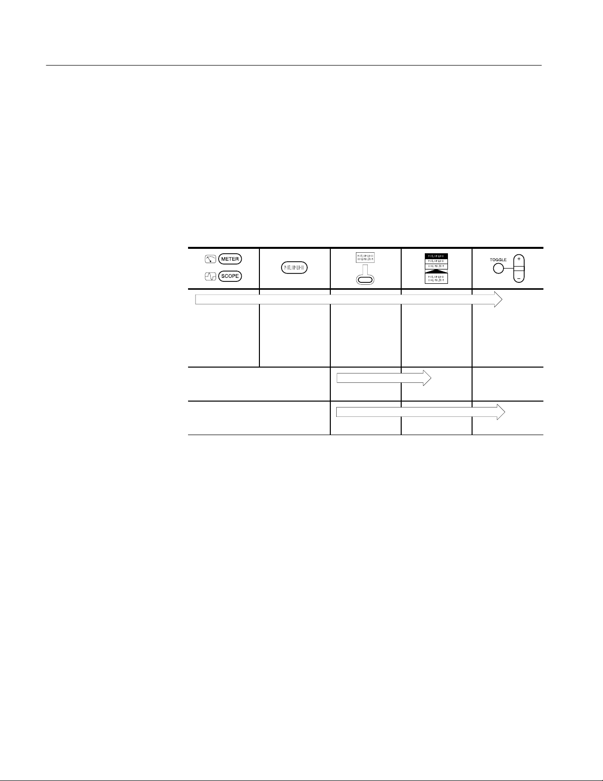
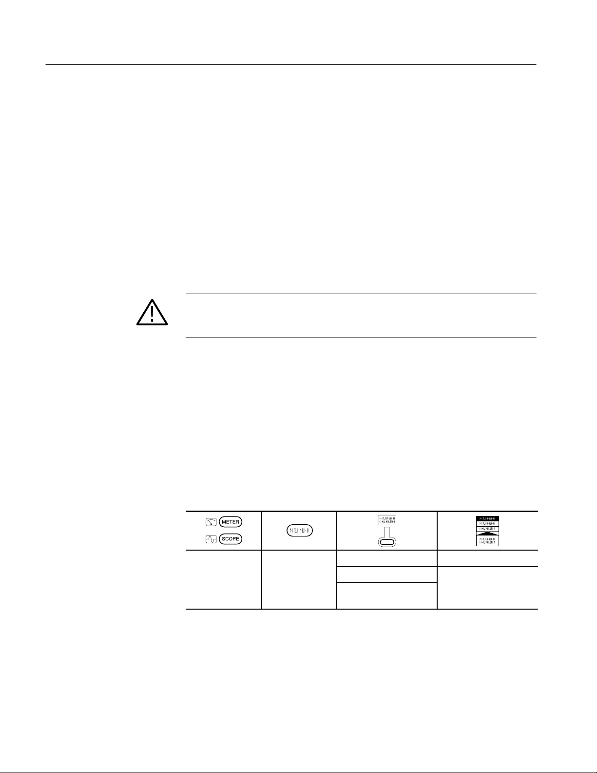
Conventions
In the Performance Verification, Adjustments, and Maintenance chapters of this
manual, TekScope instrument setups are shown in tables similar to the one
shown below.
The header of each table contains icons that represent the controls and menu
items used to set up the instrument. To make a specific setup, read the table from
left to right and then from top to bottom as shown below. The table contains the
symbol “—” if no action is required.
1. Choose scope
mode or meter
mode.
2. Press this button on the front
panel.
3. Press this
bezel button.
6. 7. —
8. 9. 10.
4. Press the
bezel button
again until this
selection is highlighted.
5. Use the
+
the value for a
parameter.
/– rocker to set
x
THS 710 & THS 720 Service Manual


Specifications
Single Sequence
oltage
ommo
t
N
This chapter contains the oscilloscope, DMM, and general specifications for the
THS 710 and THS 720 TekScope instruments. All specifications are guaranteed
unless noted “typical.” Specifications that are marked with the n symbol are
checked in the chapter Performance Verification.
All specifications apply to both the THS 710 and THS 720 unless noted
otherwise. All specifications assume horizontal MAG is off, unless noted
otherwise. To meet specifications, two conditions must first be met:
H The TekScope instrument must have been operating continuously for ten
minutes within the operating temperature range specified.
H You must perform the Compensate Signal Path operation, accessible through
the utility menu, if the ambient temperature changes by more than 5° C.
T able 1–1: Oscilloscope specifications
Acquisition
Acquisition Modes Sample (Normal), Peak detect, Envelope, and Average
Acquisition Rate,
typical
Inputs
Input Coupling DC, AC, or GND
Input Impedance,
DC Coupled
Maximum V
Between Signal and
C
n at Inpu
BNC
Maximum Voltage
Between Common
and Earth Ground
at BNC
Up to 25 waveforms per second (2 channels, sample acquisition mode,
MAG on, no measurements)
Acquisition Mode Acquisition Stops After
Sample, Peak Detect Single acquisition, one or two
channels simultaneously
Average, Envelope N acquisitions, one or two chan-
nels simultaneously, N is settable
from 2 to 256 or ∞
1 M ±1% in parallel with 25 pF ±2 pF
Overvoltage Category Maximum Voltage
CA T II Environment 300 V
CA T III Environment
For steady-state sinusoidal waveforms, derate at 20 dB/decade above
100 kHz to 13 V
Category description on page 1–10.
30 V
RMS
, 42.4 V
at 3 MHz and above. Also, refer to Overvoltage
pk
pk
150 V
RMS
RMS
THS 710 & THS 720 Service Manual
1–1

Specifications
ple
Pe
Detect or
ve-
lope
ise Time at BN
typical
T able 1–1: Oscilloscope specifications (Cont.)
Inputs
Channel-to-Channel
Common Mode
Rejection, typical
Channel-to-Channel
Crosstalk, typical
Common to Chassis
Capacitance, typical
Vertical
Number of Channels 2
Digitizers 8 bit resolution, separate digitizers for each channel sample
VOL TS/DIV Range 5 mV/div to 50 V/div at input BNC
Polarity Normal and Invert
Position Range ±10 divisions
n Analog Bandwidth
at BNC, DC Cou
(at 5 mV/div, typical)
ak
Bandwidth,
typical
En
100:1 at frequencies ≤50 MHz, measured on MATH Ch1 – Ch2
waveform, with test signal applied between signal and common of both
channels, and with the same VOLTS/DIV and coupling settings on each
channel
≥100:1 at 50 MHz, measured on one channel, with test signal applied
between signal and common of the other channel, and with the same
VOL TS/DIV and coupling settings on each channel
65 pF
simultaneously
THS 710 THS 720
d
60 MHz at input BNC
THS 710 THS 720
50 MHz (1 ms/div or slower)
100 MHz at input BNC
(90 MHz above 35° C)
75 MHz (1 ms/div or slower)
1–2
Analog Bandwidth
Limit, typical
Lower Frequency
Limit, AC Coupled,
typical
R
Peak Detect or Envelope Pulse Response,
typical
DC Gain Accuracy ±2% for Sample or Average acquisition mode
Position Accuracy ±[0.4% × |(position × volts/div)| + (0.1 div × volts/div)]
C,
Selectable between 20 MHz or full
≤10 Hz at BNC, reduced by a factor of ten when using a 10X passive
probe
THS 710 THS 720
5.8 ns 3.5 ns
Captures 50% or greater amplitude of pulses ≥ 8 ns wide (≥ 20 ns wide
at 500 ns/div)
THS 710 & THS 720 Service Manual

T able 1–1: Oscilloscope specifications (Cont.)
rement
Accuracy, Average
Sample
e
S
e
sitivity
ype
sitivity
ype
typical
Vertical
n DC Measu
Acquisition Mode
DC Measurement
Accuracy , Sample
Acq. Mode, typical
Horizontal
Rate Rang
Record Length 2500 samples for each channel
EC/DIV Rang
(including MAG)
n Sample Rate and
Delay Time Accuracy
Delay Time Range Zero to 50 s
Trigger
n Trigger Sen
Edge Trigger T
Trigger Sen
Edge Trigger T
Trigger Level Range ±4 divisions from center of screen
Trigger Level
Accuracy , typical
SET LEVEL TO 50%,
typical
Width Range, Pulse
Trigger T ype, typical
Measurement Type Accuracy
Average of ≥16 waveforms
Delta volts between any two
averages of ≥16 waveforms
acquired under same setup and
ambient conditions
±[2% × |reading + (position × volts/div)| + (0.15 div × volts/div) +
0.6 mV]
THS 710 THS 720
5 S/s to 250 MS/s, in a 1.25, 2.5,
5 sequence
THS 710 THS 720
10 ns/div to 50 s/div
±200 ppm over any ≥1 ms time interval
,
Coupling Sensitivity
DC 0.35 div from DC to 50 MHz,
,
Coupling Sensitivity
,
NOISE REJ 3.5 times the DC-coupled limits
HF REJ 1.5 times the DC-coupled limit
LF REJ 1.5 times the DC-coupled limits
±0.2 divisions, for signals having rise and fall times ≥20 ns
Operates with input signals ≥50 Hz
99 ns to 1 s, with resolution of 33 ns or approximately 1% of setting
(whichever is greater)
Specifications
±[2% × |reading +
(position × volts/div)| +
(0.1 div × volts/div)]
±[2% × |reading| +
(0.05 div × volts/div)]
5 S/s to 500 MS/s, in a 1.25, 2.5,
5 sequence
5 ns/div to 50 s/div
increasing to 1 div at 100 MHz
from DC to 30 kHz, attenuates
signals above 30 kHz
for frequencies above 1 kHz,
attenuates signals below 1 kHz
THS 710 & THS 720 Service Manual
1–3

Specifications
Si
Formats
ype
Analo
D
ple
oltage
Probe Tip
erence Le
T able 1–1: Oscilloscope specifications (Cont.)
Trigger
Width Tolerance
Range, Pulse Trigger
Type, typical
Sensitivity, Video
Trigger T ype, typical
gnal
and
Field Rates, Video
Trigger T
Holdoff Range 495 ns to 10 s
Measurements
Cursors Voltage difference between cursors (DV)
Automated
Measurements
With P6113B Probe
g Bandwidth,
C Cou
d
Probe Attenuation 10X
Maximum V
Between
and Ref
Maximum Voltage
Between Reference
Lead and Earth
Ground Using
P61 13B Probe
5%, 10%, 15%, or 20%
Composite video signal with negative sync pulse amplitude from 0.6
to 2.5 divisions
Broadcast systems Supports NTSC, PAL, and
Interlaced Field 1 or field 2
Non-interlaced Any field or any line
Line Rates 15 kHz to 65 kHz, in five ranges
Time difference between cursors (DT)
Reciprocal of DT in Hertz (1/DT)
Amplitude, Burst Width, Cycle Mean, Cycle RMS, Fall Time,
Frequency, High, Low, Max, Mean, Min, Negative Duty Cycle, Negative
Overshoot, Negative Width, Pk – Pk, Period, Positive Duty Cycle,
Positive Overshoot, Positive Width, Rise Time, and RMS
THS 710 THS 720
60 MHz
Overvoltage Category Maximum Voltage
CA T II Environment 300 V
ad
CA T III Environment
For steady-state sinusoidal waveforms, derate at 20 dB/decade above
100 kHz to 13 V
at 3 MHz and above. Also, refer to Overvoltage
pk
Category description on page 1–10.
30 V
RMS
, 42.4 V
pk
SECAM
100 MHz
RMS
150 V
RMS
1–4
THS 710 & THS 720 Service Manual

T able 1–1: Oscilloscope specifications (Cont.)
Analo
D
ple
oltage
Probe Tip
erence Le
oltage
Probe Tip
erence Le
oltage
erence
With P5102 Probe
g Bandwidth,
C Cou
d
Probe Attenuation 10X
Maximum V
Between
and Ref
DC Coupled
Maximum V
Between
and Ref
AC Coupled
Maximum V
Between Ref
Lead and Earth
Ground
Single Channel Common Lead Feedthrough with P5102
Probe, typical
THS 710 THS 720
60 MHz
Overvoltage Category Maximum Voltage
CA T II Environment 1000 V
ad,
CA T III Environment
Overvoltage Category Maximum Voltage
CA T II Environment ±1000 V
ad,
CA T III Environment
Overvoltage Category Maximum Voltage
CA T II Environment 600 V
CA T III Environment
1000:1 from DC to 100 kHz, measured on either channel, with probe tip
and reference lead connected together, and with test signal applied
between tip/reference and earth ground
A 3000 V/ms slew rate results in ≤0.5 division feedthrough, measured
on either channel, with probe tip and reference lead connected
together, and with test signal applied between tip/reference and earth
ground
100 MHz
600 V
RMS
±600 V
RMS
300 V
RMS
Specifications
RMS
DC
DC
THS 710 & THS 720 Service Manual
1–5

Specifications
oltage
ts
oltage
or
esolutio
esolutio
T able 1–2: DMM specifications
General
Resolution 33⁄4 digit, 4000 count full scale reading except as noted
Input Resistance, AC
or DC Voltage
Input Capacitance,
AC or DC Voltage,
typical
Maximum V
Between DMM and
COM Inpu
Maximum V
Between DMM
COM Input and Earth
Ground
DC Voltage
Ranges and
R
n
n Accuracy ±(0.5% of reading + 5 counts)
Normal Mode
Rejection, typical
Common Mode
Rejection, typical
AC Voltage
Conversion Type AC conversions are true RMS. The AC measurement is based on the
10 M ±10%
≤100 pF
Overvoltage Category Maximum Voltage
CA T II Environment 600 V
CA T III Environment 300 V
RMS
RMS
Overvoltage Category Maximum Voltage
CA T II Environment 600 V
CA T III Environment
300 V
RMS
RMS
Range Resolution
400.0 mV
0.1 mV
4.000 V 1 mV
40.00 V 10 mV
400.0 V 100 mV
880 V 1 V
Rejects AC signals by >60 dB at 50 Hz or 60 Hz (user selectable)
Rejects AC signals by >100 dB at 50 Hz or 60 Hz (user selectable)
AC and DC components of the signal as shown below:
1–6
AC Measurement = RMS(AC+DC) – DC
Ranges and
R
n
Range Resolution
400.0 mV
0.1 mV
4.000 V 1 mV
40.00 V 10 mV
400.0 V 100 mV
640 V 1 V
THS 710 & THS 720 Service Manual

T able 1–2: DMM specifications (Cont.)
Accuracy
esolutio
Accuracy, typical
oltage for Full
Scale Resistance
rement, typical
Ope
ircuit Voltage
typical
AC Voltage
n
Bandwidth, typical ≥5 kHz for all ranges
Common Mode
Rejection, typical
/Resistance
Ranges and
R
Bias V
Measu
n
n C
Input Waveform Maximum Error
Sinusoidal waveforms ±(2% of reading + 5 counts)
Nonsinusoidal waveforms with
crest factor up to 3
Rejects AC signals by >60 dB at DC, 50 Hz, and 60 Hz
Range Resolution
400.0
4.000 k 1
40.00 k 10
400.0 k 100
4.000 M 1 k
40.00 M 10 k
Range Maximum Error
All ranges except 40 M ±(0.5% of reading + 2 counts)
40 M ±(2% of reading + 5 counts) for
Range Full Scale Bias Voltage
400.0 350 mV
4.000 k 200 mV
40.00 k 350 mV
400.0 k 350 mV
4.000 M 400 mV
40.00 M 1.10 V
,
Range Open Circuit Voltage
400.0 4.8 V
All other ranges ≤1.2 V
Specifications
±(4% of reading + 5 counts)
0.1
≤60% relative humidity
THS 710 & THS 720 Service Manual
1–7

Specifications
J-45 Connector
Pinout
T able 1–2: DMM specifications (Cont.)
Continuity Check
Indication An audible tone is generated when measured resistance is below 50 ,
typical
Open Circuit Voltage,
typical
Test Current, typical 1 mA
Diode Check
Range Zero to 2 V, measures forward voltage drop of semiconductor junction
Voltage Accuracy,
typical
Open Circuit Voltage,
typical
Test Current, typical 1 mA
Data Logger
Horizontal Scale
Range
4.8 V
±25%
4.8 V
24 hours/div to 30 s/div (4 minutes to 8 days, full scale)
T able 1–3: General specifications
Display
Display Type 4.7 in (120 mm) diagonal liquid crystal
Display Resolution 320 horizontal by 240 vertical pixels
Display Contrast Adjustable, temperature compensated
Backlight Intensity,
typical
RS-232 Interface
Device Type DTE
R
2
35 cd/m
Pin Number Signal
1 DCD
2 DSR
3 DTR
4 GND
5 RXD
6 TXD
7 CTS
8 RTS
1–8
THS 710 & THS 720 Service Manual

Specifications
ttery
emperature
ity
Altitude
T able 1–3: General specifications (Cont.)
Probe Compensator Output
Output Voltage,
typical
Frequency, typical 1.2 kHz
Power Source
Battery Replaceable Ni-Cd battery pack
Battery Life, typical Approximately two hours of continuous use from a full charge
Low Battery Indica-
tion, typical
Battery Saver Standby Time-out and Backlight Time-out extend battery life. Time-out
Ba
Charging
Time, typical
External Power 12 VDC nominal, center positive; Operates with input from 10 VDC to
5.0 V into ≥1 M load
Low battery message first appears approximately ten minutes before
the instrument powers off automatically
ranges from 1 minute to 15 minutes, or off.
With T ekScope instrument operat-
ing
With T ekScope instrument turned
off
In external charger 1.5 hours
15 VDC
20 hours
20 hours
The DC INPUT disconnects itself automatically if >15 VDC is applied.
If this occurs, disconnect the overvoltage and then reconnect to a
voltage in the proper range.
Memory Retention,
typical
Fuse This instrument has no user-replaceable fuses
Environmental
T
Humid
All memory is retained indefinitely with battery removed and without
external power applied.
Operating –10° C to +50° C
Nonoperating –20° C to +60° C
+40° C or below ≤95% relative humidity
+41° C to +50° C ≤75% relative humudity
Operating 2,000 m
Nonoperating 15,000 m
THS 710 & THS 720 Service Manual
1–9

Specifications
ibratio
Size
t
Overvoltage
ory
T able 1–3: General specifications (Cont.)
Environmental
Random V
Drop Resistance,
typical
Mechanical
Weigh
Certifications and Compliances
Certifications Listed UL31 11-1 and CAN/CSA-C22.2 No. 1010.1-92, complies with
n Operating 2.66 g
Nonoperating 3.48 g
Survives a 30 in drop onto concrete with only cosmetic damage
Height 8.53 in (217 mm)
Width 6.95 in (177 mm)
Depth 2.00 in (50.8 mm)
With battery installed 3.2 lbs (1.5 kg)
With all standard accessories in
soft carry case
When packaged for domestic
shipment
EN61010-1
Categ
Category Examples
CA T III A typical CAT III environment is
CA T II A typical CAT II environment is
from 5 Hz to 500 Hz,
RMS
10 minutes on each axis
from 5 Hz to 500 Hz,
RMS
10 minutes on each axis
7.5 lbs (3.4 kg)
9.0 lbs (4.1 kg)
the power distribution system
within a building or factory. These
environments are somewhat
protected from lightning strikes,
but susceptible to switching
transients and other disturbances
that may generate high voltage
impulses.
the 120/240 V distribution system
within a lab or office. These
environments are fairly well
protected from external high
voltage disturbances.
1–10
THS 710 & THS 720 Service Manual

Specifications
T able 1–3: General specifications (Cont.)
Certifications and Compliances
EC Declaration of
Conformity
FCC Compliance Emissions comply with FCC Code of Federal Regulations 47 CFR, Part
Adjustment Interval
The recommended adjustment interval is one year
Meets the intent of Directive 89/336/EEC for Electromagnetic
Compatibility and Low-Voltage Directive 73/23/ECC for Product Safety.
Compliance was demonstrated to the following specifications as listed
in the official Journal of the European Communities:
EN 55011 Class A: Radiated and Conducted Emissions
13
EN 50081–1 Emissions:
EN 60555–2 Power Harmonics
EN 50082–1 Immunity:
IEC 801–2 Electrostatic Discharge
IEC 801–3 RF Radiated
2
IEC 801–4 Fast Transients
IEC 801–5 Surge
3
EN 61010–1 Safety
1
Tektronix-supplied ferrite bead required on instrument end of
RS-232 cable
2
Performance criteria: ≤ 5.0 div increase in peak to peak noise
(Sample acquisition mode, full bandwidth); otherwise, ≤ 1.0 div
increase in peak to peak noise
3
Applies to instrument operating with Tektronix-supplied AC
adapter
15, Subpart B, Class A
THS 710 & THS 720 Service Manual
1–11

Specifications
1–12
THS 710 & THS 720 Service Manual


Operator Information
This chapter provides a quick overview of the following topics:
H Internal and external power sources
H Understanding the front panel
H Connecting and using the probes
For more detailed information about TekScope instrument operation, refer to the
THS 710 & THS 720 User Manual.
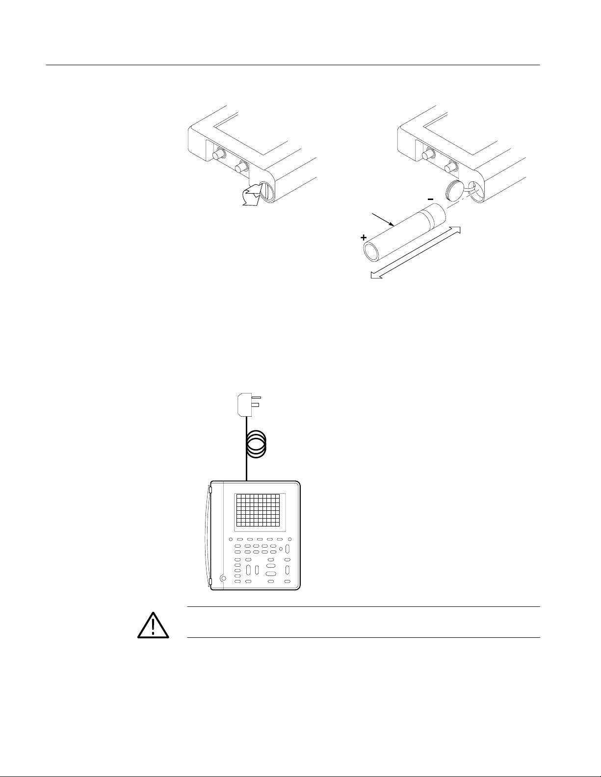
Internal and External Power Sources
You can power the TekScope instrument from the internal battery pack or from
the AC adapter (both are standard accessories).
Using the Battery Pack
Before using the battery for the first time, it must be charged. You can use
external power to charge the battery pack while it is in the TekScope instrument.
Or you can charge the battery pack with the optional external battery charger.
Typical battery charging times are listed below.
Configuration Typical Charging Time
Battery pack in TekScope instrument 20 hours
Battery pack in external charger 1.5 hours
You can remove and replace the battery pack without losing any saved
information. The current setup, saved setups, saved waveforms, and saved data
are stored in nonvolatile memory that does not depend on battery power.
CAUTION. To prevent loss of saved information, set the ON/STBY switch to STBY
before removing the battery pack.
THS 710 & THS 720 Service Manual
2–1
Operator Information
Battery pack
Using External Power
For benchtop operation, you can use external power. Attach the AC adapter
as shown below.
The DC INPUT disconnects itself if an overvoltage is applied. If this
occurs, disconnect and then reconnect the AC adapter to resume operation
from external power.
External power
to DC INPUT
2–2
CAUTION. To avoid overheating, do not connect external power while the
instrument is in a confined space, such as in the soft case.
THS 710 & THS 720 Service Manual
Understanding the Front Panel
The SCOPE and METER buttons select the operating mode. The front panel has
additional buttons for the functions you use most often and menus to access the
more specialized functions.
Operator Information
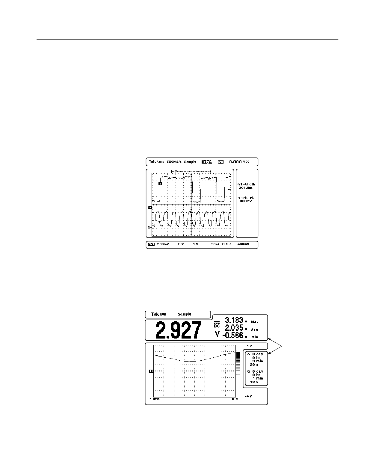
Using Scope Mode
Using Meter Mode
Press the front-panel SCOPE button to enter scope mode. Then, press AUTORANGE to set the vertical, horizontal, and trigger automatically for a usable
display. A typical scope-mode display is shown below.
Status line
Graticule
area
Waveform readout lines
Measurement
readout area
Press the front-panel METER button to enter meter mode. Press one of the bezel
buttons to choose a meter function and then press AUTORANGE to set the range
automatically. A typical meter-mode display is shown below.
Graticule
THS 710 & THS 720 Service Manual
Status line
Measurement
readout areas
area
2–3

Operator Information
Using the Menu System
To use the menu system, follow the steps below:
1. Press a front-panel button to display the menu you want to use.
2. Press a bezel button to choose a menu item. If a pop-up menu appears,
continue to press the bezel button to choose an item in the pop-up menu. You
may need to press the Select Page button to access additional menu items.
2–4
THS 710 & THS 720 Service Manual

Operator Information
3. After choosing some menu items, you need to set a numerical parameter to
complete the setup. Use the
+
/– rocker to adjust the parameter or press the
TOGGLE button to reset the parameter to its default value.
4. If the OK bezel button is displayed, press it to confirm your choice.
NOTE. In the Performance Verification, Adjustments, and Maintenance chapters
of this manual, TekScope instrument setups are shown in tables. Refer to
Conventions on page x for information about reading these tables.
THS 710 & THS 720 Service Manual
2–5

Operator Information
Using the Dedicated
Buttons
You can use the dedicated buttons below to take direct actions. These buttons do
not require the use of menus.
31
2
4
16
15
14
87910111213
5
6
1. HARD COPY. Initiates a hard copy using the RS-232 port.
2. HOLD. Stops/restarts oscilloscope acquisition or holds/resets meter readout.
3. AUTORANGE. Selects oscilloscope or meter autorange function.
4. CLEAR MENU. Clears menu from display.
5. TRIGGER LEVEL. Adjusts trigger level.
6. SET LEVEL TO 50%. Sets trigger level to midpoint of oscilloscope
waveform.
7. HORIZONTAL POSITION. Adjusts oscilloscope waveform horizontal
position.
8. MAG. Turns 10X horizontal magnification on and off.
9. SEC/DIV. Adjusts waveform horizontal scale factor for oscilloscope or data
logger.
10. VERTICAL POSITION. Adjusts oscilloscope waveform vertical position.
11. WAVEFORM OFF. Removes selected oscilloscope waveform from display.
12. VOLTS/DIV. Adjusts oscilloscope vertical scale factor or meter range.
13. ON/STBY. Selects on or standby. Does not disconnect power from the
instrument.
14. CH 1, CH 2, MATH, REF A, REF B. Displays waveform and chooses
selected waveform.
2–6
THS 710 & THS 720 Service Manual

15. SCOPE. Selects scope mode.
16. METER. Selects meter mode.
Connecting and Using the Probes
The oscillscope probes and meter leads attach to the connectors located on the
top and side panels of the TekScope instrument.
Operator Information
Top panel
THS 710 & THS 720 Service Manual
Side panel
2–7

Operator Information
Compensating the
Oscilloscope Probes
To maintain signal fidelity, you must compensate each voltage probe for the
channel input it is connected to.
1. Connect the oscilloscope probe and then press AUTORANGE.
Ch 1
Probe reference lead to
Probe tip to PROBE COMP
AUTORANGE
2. Check the shape of the displayed waveform.
Overcompensated
Undercompensated
Compensated correctly
3. If necessary, adjust the probe for correct compensation.
P6113B P5102
4. Repeat these steps for the other probe and channel.
2–8
THS 710 & THS 720 Service Manual

Operator Information
Attaching the Reference
Leads Correctly
Beware of High Voltages
If you are using both of the oscilloscope channels, you must attach the probe
reference lead for each channel directly to your circuit. These attachments are
required because the oscilloscope channels are electrically isolated; they do not
share a common chassis connection. If you are also using the DMM, you must
also attach the DMM common lead to your circuit for the same reason as above.
Understand the voltage ratings for the probes you are using and do not exceed
those ratings. Two ratings are important to know and understand:
H The maximum measurement voltage from the probe tip to the probe
reference lead
H The maximum floating voltage from the probe reference lead to earth ground
These two voltage ratings depend on the probe and your application. Refer to
Specifications beginning on page 1–1 for more information.
WARNING. To prevent electrical shock, do not exceed the measurement or
floating voltage ratings for the oscilloscope input BNC connector, probe tip,
probe reference lead, DMM input connector, or DMM lead.
THS 710 & THS 720 Service Manual
2–9

Operator Information
2–10
THS 710 & THS 720 Service Manual


Theory of Operation
This chapter describes the electrical operation of the TekScope instrument to the
module level. It describes the basic operation of each functional circuit block
shown in Figure 3–1.
Main Board
The Main board assembly contains the following oscilloscope and meter
functions.
Oscilloscope Signal Path
Meter Signal Path
Processor System
Display System
Power Supply
Each of the two oscilloscope input signals enters the main board and passes
through an attenuator and buffer amplifier. Then each signal passes through an
isolation interface before reaching the trigger circuitry, a sampler, and a digitizer.
The digitized signals are written into system memory for transfer to the display
system.
The DMM input enters the Main board and passes through a switching network
to select the meter function and range. The DMM signal is then sampled and
digitized.
The processor system contains a 68331 microprocessor that controls the entire
instrument. The processor passes waveforms, meter readings, and text on to the
display system. The processor system also contains flash ROM, system RAM,
and the RS-232, keyboard, and probe compensation interfaces.
The display system, consisting of a display controller and video memory,
processes text and waveforms to refresh the display.
The power supply provides DC power to ciruits on the main board and generates
an AC voltage to provide power to the attenuators and buffer amplifiers across
the isolation interfaces. It also provides +12 V and –20 V for the display module.
Inverter Board
The inverter board generates an AC voltage for the display backlight.
THS 710 & THS 720 Service Manual
3–1

Theory of Operation
Display Module
Switch Assembly
The display module consists of a liquid crystal display (LCD), a display driver,
and a flourescent backlight.
The switch assembly is a matrix of switches that form the front-panel buttons.
The switch assembly consists of a flex-circuit board and an elastomeric switch
mat. Switch closures are read by the processor system.
Battery
Adjustment-
lockout
Not used
12
EXT
PWR
2
J8
2
J3
80
J1
J9
CH 1 CH 2
J7 J6
Main board
PROBE
COMP
8
J5
RS-232
COM
DMM
3–2
5
Inverter boardDisplay assembly Switch assembly
2
Figure 3–1: Module-level block diagram
17
THS 710 & THS 720 Service Manual


Performance Verification
vetek 9100
iversal
loscope
libratio
le
Fluke 5500A
lti-product
libration Optio
Optio
libration Optio
Optio
This chapter contains performance verification procedures for the specifications
marked with the n symbol. The following equipment, or a suitable equivalent,
is required to complete these procedures.
Description
DC Voltage Source 60 mV to 800 V, ±0.1% accu-
AC Voltage Source 300 mV to 640 V, ±0.5%
Leveled Sine Wave Generator 50 kHz and 100 MHz, ±3%
Time Mark Generator 10 ms period, ±50 ppm accu-
Minimum
Requirements
racy
accuracy at 500 Hz
amplitude accuracy
racy
Examples
Wa
Calibration System with Oscil-
(Option 250)
Calibrator with Oscilloscope
Ca
Ca
5500A-SC)
Ca
Mu
Un
n Modu
n (
n (
n
n
Banana to Banana Cable (two
required)
50 BNC Cable BNC male to BNC male,
50 Feedthrough Termination
Dual Banana to BNC Adapter Banana plugs to BNC female Tektronix part number
Shielded banana jacks on
each end
≈ 36 in (1 m) long
BNC male and female con-
nectors
Tektronix Deluxe Meter Lead
Set (012-1483-00)
Tektronix part number
012-0482-00
Tektronix part number
01 1-0049-01
103-0090-00
THS 710 & THS 720 Service Manual
4–1

Performance Verification
re-
ment Accuracy
re-
ment Accuracy
Test Record
Serial
Number
Test Passed Failed
Self Test
Oscilloscope Tests Low Limit T est Result High Limit
Channel 1 DC Measu
Procedure Performed by Date
5 mV/div 34.05 mV 35.95 mV
500 mV/div 3.405 V 3.595 V
2 V/div 13.62 V 14.38 V
10 V/div 68.1 V 71.9 V
Channel 2 DC Measu
Channel 1 Bandwidth 425 mV —
Channel 2 Bandwidth 425 mV —
Sample Rate and Delay Time Accuracy –4 divs +4 divs
Channel 1 Edge Trigger Sensitivity Stable trigger —
Channel 2 Edge Trigger Sensitivity Stable trigger —
5 mV/div 34.05 mV 35.95 mV
500 mV/div 3.405 V 3.595 V
2 V/div 13.62 V 14.38 V
10 V/div 68.1 V 71.9 V
4–2
THS 710 & THS 720 Service Manual

Performance Verification
D
oltage Accuracy
A
oltage Accuracy
DMM Tests Low Limit Test Result High Limit
C V
400 mV range,
60 mV input
59.2 mV 60.8 mV
C V
400 mV range,
360 mV input
4 V range 3.577 V 3.623 V
40 V range 35.77 V 36.23 V
400 V range 357.7 V 362.3 V
880 V range 783 V 801 V
400 mV range 352.3 mV 367.7 mV
4 V range,
600 mV input
4 V range,
3.6 V input
40 V range 35.23 V 36.77 V
400 V range 352.3 V 367.7 V
640 V range 559 V 593 V
357.7 mV 362.3 mV
0.583 V 0.617 V
3.523 V 3.677 V
THS 710 & THS 720 Service Manual
4–3
Performance Verification
SCOP
I
I
Y
—
Performance Verification Procedures
In these procedures, TekScope instrument setups are shown in tables. Refer to
Conventions on page x for information about how to use these tables.
Before beginning these procedures, two conditions must first be met:
H The TekScope instrument must have been operating continuously for ten
minutes within the operating temperature range specified.
H You must perform the Signal Path Compensation operation described below.
If the ambient temperature changes by more than 5° C, you must perform the
Signal Path Compensation operation again.
The time required to complete the entire procedure is approximately one hour.
WARNING. Some procedures use hazardous voltages. To prevent electrical shock,
always set voltage source outputs to 0 V before making or changing any
interconnections.
Signal Path Compensation
Signal path compensation optimizes the oscilloscope accuracy for the current
ambient temperature. For maximum accuracy, recompensate the signal path if the
ambient temperature changes by 5° C or more.
To compensate the signal path, perform the following steps:
1. Disconnect any probes or cables from the channel 1 and channel 2 input
BNC connectors.
2. Execute the signal path compensation with the following steps:
EUT
L
T
System Cal
Signal Path
OK Compensate Signal
Paths
3. When the signal path compensation is complete, press CLEAR MENU to
resume operation of the TekScope instrument.
4–4
THS 710 & THS 720 Service Manual

Performance Verification
SCOP
I
I
Y
—
Execute Self Test
This procedure uses internal routines to verify that the TekScope instrument
functions and passes its internal self tests. No test equipment or hookups are
required. Start the self test with the following setup:
EUT
L
T
System Diag
Loop Once
Execute
OK Run Test
A dialog box displays the result when the self test completes. Press the CLEAR
MENU button to continue operation.
THS 710 & THS 720 Service Manual
4–5

Performance Verification
SCOP
SA
—
—
AS
—
Check Oscilloscope DC
Measurement Accuracy
This test checks the DC measurement accuracy of the oscilloscope.
1. Set the DC voltage source output level to 0 V.
2. Set up the TekScope instrument using the following steps:
E
* You may need to press Select Page to display this selection.
VE/
RECALL
CH 1 —
VERTICAL
MENU
ACQUIRE Mode Average Set to 16
ME
Recall Saved
Setup
OK Recall
Factory
Probe Type Voltage Probe Set to 1X
Select Measrmnt Mean*
OK Select
Measrmnt
Recall Factory
Setup
—
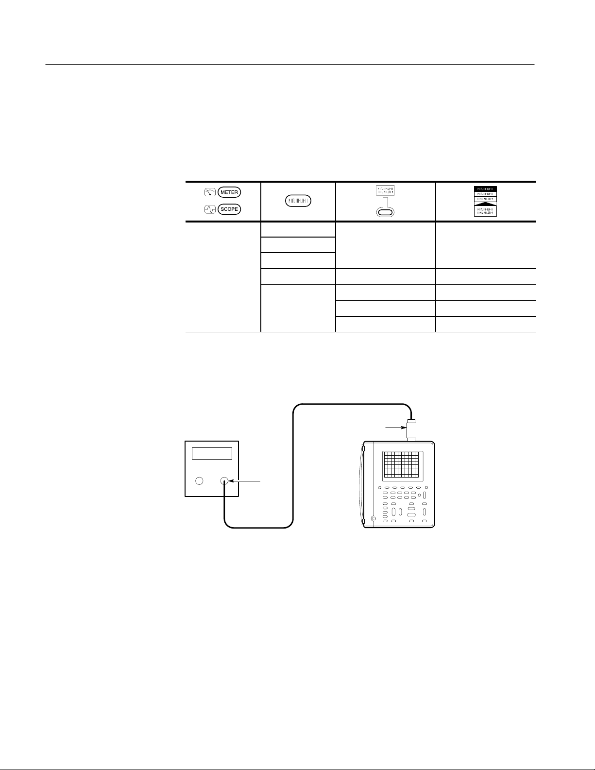
3. Connect the TekScope instrument to the DC voltage source as shown below.
DC voltage
source
+–
Dual banana
to bnc adapter
BNC cable
Ch 1
4–6
THS 710 & THS 720 Service Manual

Performance Verification
4. For each VOLTS/DIV setting listed below, perform the following steps:
a. Set the DC voltage source output level to the positive voltage listed and
then record the mean measurement as V
pos
.
b. Reverse the polarity of the DC voltage source and then record the mean
measurement as V
neg
.
c. Calculate V
diff
= V
pos
– V
and then compare V
neg
to the accuracy
diff
limits in the table.
DC Voltage Source Output
VOL TS/DIV Setting
5 mV/div +17.5 mV, –17.5 mV 34.05 mV to 35.95 mV
500 mV/div +1.75 V, –1.75 V 3.405 V to 3.595 V
2 V/div +7.00 V, –7.00 V 13.62 V to 14.38 V
10 V/div +35.0 V, –35.0 V 68.1 V to 71.9 V
Levels
Accuracy Limits for V
diff
5. Set DC voltage source output level to 0 V.
6. To check channel 2, repeat step 2 substituting CH 2 for CH 1.
7. Press CH 1 and WAVEFORM OFF to remove the channel 1 waveform
from the display.
8. Repeat steps 3 through 5, substituting CH 2 for CH 1, to complete the check
of channel 2.
THS 710 & THS 720 Service Manual
4–7

Performance Verification
SCOP
SA
—
—
AS
—
Check Oscilloscope
Channel 1 Bandwidth
This test checks the bandwidth of channel 1.
1. Set up the TekScope instrument using the following steps:
E
* You may need to press Select Page to display this selection.
VE/
RECALL
ACQUIRE Mode Average Set to 16
TRIGGER Coupling Noise Reject
ME
Recall Saved
Setup
OK Recall
Factory
High-Low Setup Min-Max
Select Measrmnt Pk-Pk*
OK Select
Measrmnt
Recall Factory
Setup
—
—
2. Connect the TekScope instrument to the leveled sine wave generator as
shown below.
Leveled
sine wave
generator
Output
BNC cable
50 feedthrough
terminator
Ch 1
4–8
THS 710 & THS 720 Service Manual

Performance Verification
3. Set the TekScope instrument VOLTS/DIV to 100 mV/div.
4. Set the TekScope instrument SEC/DIV to 10 s/div.
5. Set the leveled sine wave generator frequency to 50 kHz.
6. Set the leveled sine wave generator output level so the peak-to-peak
measurement is between 599 mV and 601 mV.
7. Set the leveled sine wave generator frequency to 60 MHz if you are checking
a THS 710 or to 100 MHz if you are checking a THS 720.
8. Set the TekScope instrument SEC/DIV to 10 ns/div.
9. Check that the peak-to-peak measurement is ≥425 mV.
10. Proceed to the next test to check the channel 2 bandwidth.
THS 710 & THS 720 Service Manual
4–9

Performance Verification
SCOP
—
—
AS
Check Oscilloscope
Channel 2 Bandwidth
This test checks the bandwidth of channel 2.
1. First check the channel 1 bandwidth using the previous test. Then, perform
these additional steps to check the channel 2 bandwidth:
E
* You may need to press Select Page to display this selection.
CH 1
WAVEFORM OFF
CH 2
TRIGGER Source Ch2
ME
High-Low Setup Min-Max
Select Measrmnt Pk-Pk*
OK Select Measrmnt —
2. Connect the TekScope instrument to the leveled sine wave generator as
shown below.
Leveled
sine wave
generator
Output
BNC cable
50 feedthrough
terminator
Ch 2
4–10
THS 710 & THS 720 Service Manual

Performance Verification
3. Set the TekScope instrument VOLTS/DIV to 100 mV/div.
4. Set the TekScope instrument SEC/DIV to 10 s/div.
5. Set the leveled sine wave generator frequency to 50 kHz.
6. Set the leveled sine wave generator output level so the peak-to-peak
measurement is between 599 mV and 601 mV.
7. Set the leveled sine wave generator frequency to 60 MHz if you are checking
a THS 710 or to 100 MHz if you are checking a THS 720.
8. Set the TekScope instrument SEC/DIV to 10 ns/div.
9. Check that the peak-to-peak measurement is ≥425 mV.
THS 710 & THS 720 Service Manual
4–11

Performance Verification
SCOP
SA
—
Check Oscilloscope
Sample Rate and Delay
Time Accuracy
This test checks the oscilloscope time base accuracy.
1. Set up the TekScope instrument using the following steps:
E
VE/
RECALL
VERTICAL
MENU
Recall Saved
Setup
OK Recall
Factory
Probe Type Voltage Probe Set to 1X
Recall Factory
Setup
—
2. Connect the TekScope instrument to the time mark generator as shown
below.
Time mark
generator
50 feedthrough
terminator
Ch 1
Output
BNC cable
4–12
THS 710 & THS 720 Service Manual

Performance Verification
SCOP
—
SCOP
3. Set the time mark generator period to 10 ms.
4. Set the TekScope instrument VOLTS/DIV to 500 mV/div.
5. Set the TekScope instrument SEC/DIV to 2 ms/div.
6. Use the vertical POSITION rocker to center the test signal on screen.
7. Press SET LEVEL TO 50%.
8. Change the TekScope instrument setup using the following steps:
E
HORIZONTAL MENU
CLEAR
MENU
Time Base Delayed Runs After
Main
— —
9. Set the delayed time base SEC/DIV to 500 ms/div.
10. Change the TekScope instrument setup using the following steps:
E
HORIZONTAL MENU
CLEAR
MENU
Time Base Delayed Runs After
Main
— — —
Set delay time to
10 ms
11. Set the delayed time base SEC/DIV to 500 ns/div.
12. Check that the rising edge of the marker crosses the center horizontal
graticule line within ±4 divisions of center graticule.
NOTE. One division of displacement from graticule center corresponds to
a 50 ppm time base error.
THS 710 & THS 720 Service Manual
4–13

Performance Verification
SCOP
SA
—
—
AS
Check Oscilloscope
Channel 1 Edge Trigger
Sensitivity
This test checks the edge trigger sensitivity for channel 1.
1. Set up the TekScope instrument using the following steps:
E
* You may need to press Select Page to display this selection.
VE/
RECALL
ACQUIRE Mode Average Set to 16
TRIGGER Mode Normal
ME
Recall Saved
Setup
OK Recall
Factory
High-Low Setup Min-Max
Select Measrmnt Ampl*
OK Select
Measrmnt
Recall Factory
Setup
—
—
2. Connect the TekScope instrument to the leveled sine wave generator as
shown below.
Leveled
sine wave
generator
Output
BNC cable
50 feedthrough
terminator
Ch 1
4–14
THS 710 & THS 720 Service Manual

Performance Verification
3. Set the leveled sine wave generator frequency to 100 MHz.
4. Set the TekScope instrument VOLTS/DIV to 500 mV/div.
5. Set the TekScope instrument SEC/DIV to 10 ns/div.
6. Set the leveled sine wave generator output level to approximately 50 mV
p-p
so that the measured amplitude is approximately 500 mV. (The measured
amplitude can fluctuate around 500 mV.)
7. Press SET LEVEL TO 50%. Adjust TRIGGER LEVEL as necessary and
then check that triggering is stable.
8. Change the TekScope instrument setup using the following steps:
SCOPE TRIGGER Slope \ (falling edge)
9. Press SET LEVEL TO 50%. Adjust TRIGGER LEVEL as necessary and
then check that triggering is stable.
10. Change the TekScope instrument setup using the following steps:
SCOPE TRIGGER Slope / (rising edge)
11. Proceed to the next test to check the channel 2 edge trigger sensitivity.
THS 710 & THS 720 Service Manual
4–15
Performance Verification
SCOP
—
—
AS
Check Oscilloscope
Channel 2 Edge Trigger
Sensitivity
This test checks the edge trigger sensitivity for channel 2.
1. First check the channel 1 edge trigger sensitivity using the previous test.
Then, perform these additional steps to check the channel 2 edge trigger
sensitivity:
E
* You may need to press Select Page to display this selection.
CH 1
WAVEFORM OFF
CH 2
TRIGGER Source Ch2
ME
High-Low Setup Min-Max
Select Measrmnt Ampl*
OK Select Measrmnt —
2. Connect the TekScope instrument to the leveled sine wave generator as
shown below.
Leveled
sine wave
generator
Output
BNC cable
50 feedthrough
terminator
Ch 2
4–16
THS 710 & THS 720 Service Manual

Performance Verification
3. Set the leveled sine wave generator frequency to 100 MHz.
4. Set the TekScope instrument VOLTS/DIV to 500 mV/div.
5. Set the TekScope instrument SEC/DIV to 10 ns/div.
6. Set the leveled sine wave generator output level to approximately 50 mV
p-p
so that the measured amplitude is approximately 500 mV. (The measured
amplitude can fluctuate around 500 mV.)
7. Press SET LEVEL TO 50%. Adjust TRIGGER LEVEL as necessary and
then check that triggering is stable.
8. Change the TekScope instrument setup using the following steps:
SCOPE TRIGGER Slope \ (falling edge)
9. Press SET LEVEL TO 50%. Adjust TRIGGER LEVEL as necessary and
then check that triggering is stable.
THS 710 & THS 720 Service Manual
4–17

Performance Verification
Check Meter DC Voltage
Accuracy
This test checks the meter DC voltage accuracy.
1. Set the DC voltage source output level to 0 V.
2. Set up the TekScope instrument using the following steps:
METER — VDC —
3. Connect the TekScope instrument to the DC voltage source as shown below.
DC voltage
source
+–
Banana cables
4–18
THS 710 & THS 720 Service Manual

Performance Verification
4. For each range, set the DC voltage source output to the level listed below,
and then compare the meter reading to the accuracy limits.
DC Voltage Source
Range
400 mV 60 mV 59.2 mV to 60.8 mV
400 mV 360 mV 357.7 mV to 362.3 mV
4 V 3.6 V 3.577 V to 3.623 V
40 V 36 V 35.77 V to 36.23 V
400 V 360 V 357.7 V to 362.3 V
880 V 792 V 783 V to 801 V
Output Level
Accuracy Limits
5. Set the DC voltage source output level to 0 V.
THS 710 & THS 720 Service Manual
4–19

Performance Verification
Check Meter AC Voltage
Accuracy
This test checks the meter AC voltage accuracy.
1. Set the AC voltage source output level to 0 V.
2. Set up the TekScope instrument using the following steps:
METER — VAC —
3. Connect the TekScope instrument to the AC voltage source as shown below.
AC voltage
source
Banana cables
4–20
THS 710 & THS 720 Service Manual

Performance Verification
4. Set the AC voltage source output frequency to 500 Hz.
5. For each range, set the AC voltage source output to the level listed below,
and then compare the meter reading to the accuracy limits.
AC Voltage Source
Range
400 mV 360 mV 352.3 mV to 367.7 mV
4 V 600 mV 0.583 V to 0.617 V
4 V 3.6 V 3.523 V to 3.677 V
40 V 36 V 35.23 V to 36.77 V
400 V 360 V 352.3 V to 367.7 V
640 V 576 V 559 V to 593 V
Output Level
Accuracy Limits
6. Set the AC voltage source output level to 0 V.
This completes the performance verification procedure.
THS 710 & THS 720 Service Manual
4–21

Performance Verification
4–22
THS 710 & THS 720 Service Manual


Adjustment Procedures
vetek 9100
iversal
loscope
libratio
le
Fluke 5500A
lti-product
libration Optio
Optio
libration Optio
Optio
This chapter contains adjustment procedures for the TekScope instrument.
Only qualified personnel should perform service procedures. Read this Service
Safety Summary and the General Safety Summary before performing any service
procedures. Also refer to the chapter Operating Information for information
about using the TekScope instrument.
NOTE. The voltage references inside the TekScope instrument are very stable over
time and should not require routine adjustment. Before performing any procedure in this chapter, first verify that the instrument does not meet specifications.
Refer to the chapter Performance Verification for procedures to verify the
specifications.
Required Equipment
The following equipment, or a suitable equivalent, is required to complete these
procedures.
Minimum
Description
DC Voltage Source 400 mV to 800 V , ±0.1%
AC Voltage Source 400 mV to 600 V, ±0.5%
Resistance Standard 100 to 10 M, ±0.1%
Fast-Rise Square Wave
Generator
Banana to Banana Cable (two
required)
50 BNC Cable BNC male to BNC male,
50 BNC Cable BNC male to BNC male,
50 Feedthrough
Termination
Requirements
accuracy
accuracy at 500 Hz
accuracy
300 mV step, ≤ 1 ns risetime
Shielded banana jacks on
each end
≈ 36 in (1 m) long
≈ 10 in (25 cm) long
BNC male and female connectors
Examples
Wa
Calibration System with Oscil-
(Option 250)
Calibrator with Oscilloscope
Ca
Ca
5500A-SC)
Tektronix Deluxe Meter Lead
Set (012-1483-00)
Tektronix part number
012-0482-00
Tektronix part number
012-0208-00
Tektronix part number
01 1-0049-01
Ca
Mu
Un
n Modu
n (
n (
n
n
THS 710 & THS 720 Service Manual
5–1

Adjustment Procedures
Minimum
Description Examples
Dual Banana to BNC Adapter Banana plugs to BNC female Tektronix part number
Requirements
103-0090-XX
BNC T One male and two female
Overview of the Adjustment Process
The TekScope instrument is protected from inadvertent adjustment by an internal
adjustment-lockout jumper. Some disassembly is required to access and remove
the jumper before you can adjust the instrument. After adjustment is complete,
the jumper should be replaced to protect the calibration of the instrument.
Oscilloscope adjustment and meter adjustment are independent procedures. You
can choose to adjust either or both. Each procedure consists of a series of steps;
as you move through these steps, the TekScope instrument display provides
instructions that describe the specific input signal requirements for each step.
NOTE. During some steps, the instrument may appear to be idle for several
minutes while it is processing information internally. Please have patience.
If all steps in the procedure are completed successfully, a “Pass” message is
displayed and the new calibration constants take affect. If any step fails, the
procedure is aborted and the current calibration is not affected. You can also
choose to abort the procedure at any step.
BNC connectors
Tektronix part number
103-0030-XX
5–2
Before performing adjustment procedures, you must warm up the instrument at
least ten minutes in an ambient temperature between 20° C and 30° C. Adjustments performed prior to warm-up or outside this temperature range may result
in poor performance.
In this manual, TekScope instrument setups are shown in tables. Refer to
Conventions on page x for information about how to use these tables.
THS 710 & THS 720 Service Manual

Accessing the Adjustment-Lockout Jumper
Before adjusting the instrument you must (temporarily) remove the internal
adjustment-lockout jumper. You will need a 12 in ⋅ lb (1.3 N ⋅ m) torque-limiting
screwdriver with Torx T-15 tip and a pair of needle-nose pliers to access and
remove the jumper.
WARNING. Before doing this or any other procedure in this manual, read the
General Safety Summary and Service Safety Summary found at the beginning of
this manual. Also, to prevent possible injury to service personnel or damage to
electrical components, read Preventing ESD on page 6–1.
Use this procedure to access and remove the adjustment-lockout jumper.
1. Disconnect all probes, cables, or meter leads from the instrument.
2. Disconnect the AC adapter, open the battery door, and remove the battery.
3. Place the TekScope instrument face down on a soft surface (such as an
anti-static mat).
Adjustment Procedures
4. Use the torque-limiting Torx T-15 screwdriver to remove the four screws
that hold the case together.
5. Holding the case together, pick it up and place it back side down on a soft
surface.
6. As you lift the front cover off the instrument, press the buttons as necessary
to prevent the switch mat from coming off with the front cover.
7. To remove the switch mat, lift it off the switch flex-circuit assembly. Place it
button-side down on a clean surface.
CAUTION. To avoid contamination of switch contacts, do not touch the carbon
contacts on the switch flex-circuit assembly or on the back side of the switch
mat.
8. Fold the switch flex-circuit assembly toward you to expose the display
module, inverter board, and adjustment-lockout jumper. The jumper location
is shown in Figure 5–1.
9. Use the needle nose pliers to remove the adjustment-lockout jumper from the
instrument. Set the jumper aside for replacement after the adjustment is
complete.
10. To reassemble the instrument, fold the switch flex-circuit assembly back
THS 710 & THS 720 Service Manual
over the display module and inverter board.
5–3

Adjustment Procedures
Adjustment-lockout
jumper
Figure 5–1: Location of adjustment-lockout jumper
11. To install the switch mat, place it (contact side down) on the switch
flex-circuit assembly. The five rubber guideposts fit into holes in the circuit
board.
12. Place the front cover assembly onto the instrument. Taking care not to pinch
the handle, align it into the guides in the front cover. Align the buttons so
they all protrude through the holes in the front cover.
13. Holding the case together, pick it up and place it front side down on a soft
surface.
CAUTION. To avoid cross-threading or cutting new threads with the screws,
carefully follow the procedure in the next step.
14. To install the four screws, follow these steps:
a. Place the screws into their holes in the back cover.
b. Using the torque-limiting Torx T-15 screwdriver, slowly turn each
screw backward (counterclockwise) until you feel the thread drop and
then gently tighten the screw (turn clockwise) into the existing thread.
5–4
THS 710 & THS 720 Service Manual

15. Replace the battery as shown on page 2–2, and then close the battery door.
Oscilloscope Adjustment
Three equipment setups, shown in Figure 5–2, are required to complete this
adjustment procedure. For each step in the procedure, the specific input signal
required by that step is described in the TekScope instrument display. Refer to
these diagrams as necessary during the procedure. Table 5–1 summarizes the
steps in the procedure and the signal requirement for each step.
T able 5–1: Summary of oscilloscope adjustment steps
Step Uses Equipment Setup Signal Source Setting
1 Square wave generator setup Fast rise output, 300 mV
Adjustment Procedures
c. When all four all screws are in, hold a corner of the case together firmly
to compress the gasket while tightening its screw until snug. Repeat for
the other corners. Do not overtighten the screws (14 in ⋅ lbs or 1.5 N ⋅ m
maximum torque).
p-p
amplitude, 1 kHz frequency
2 Zero voltage setup None
5 DC voltage setup +7.000 V
6 DC voltage setup –7.000 V
7 DC voltage setup +700.0 mV
8 DC voltage setup –700.0 mV
9 DC voltage setup +70.00 mV
10 DC voltage setup –70.00 mV
THS 710 & THS 720 Service Manual
5–5

Adjustment Procedures
Square wave generator setup
Fast rise square
wave generator
Output
36 inch BNC cable
Zero voltage setup
BNC ‘T’ connector
BNC ‘T’ connector
10 inch BNC cable
Ch 1
10 inch BNC cable
Ch 1
50 feedthrough
terminator
Ch 2
50 feedthrough
terminator
Ch 2
5–6
DC voltage setup
DC voltage
source
BNC ‘T’ connector
+–
Dual banana
to bnc adapter
36 inch BNC cable
Figure 5–2: Oscilloscope adjustment setups
10 inch BNC cable
Ch 1
Ch 2
THS 710 & THS 720 Service Manual

Adjustment Procedures
SCOP
I
I
Y
—
Oscilloscope Adjustment
Procedure
After removing the adjustment-lockout jumper, use this procedure to adjust the
oscilloscope voltage references.
1. Turn on the TekScope instrument and let it warm up for at least ten minutes.
2. Connect the fast rise square wave generator to the instrument as shown in the
Square wave generator setup of Figure 5–2.
3. Set the fast rise square wave generator amplitude to 300 mV
(±10 mV
p-p
p-p
and frequency to 1 kHz (1 ms period).
4. Use the TekScope instrument setup below to start the oscilloscope adjust-
ment process. For each step, follow the specific instructions displayed by the
instrument to connect the correct signal source and then confirm that you are
ready to proceed to the next step.
EUT
L
T
System Cal
Factory Scope
OK Factory Cal Scope
)
Completing the
Adjustment Process
NOTE. During some steps, the instrument may appear to be idle for several
minutes while it is processing information internally. Please have patience.
If any step in the procedure fails, the procedure terminates. Failure will result if
an incorrect signal source is connected. If this happens, you must start the
procedure over from the beginning.
If the procedure completes successfully, a “Pass” message is displayed and the
new adjustment takes effect.
After adjusting the oscilloscope, continue with one of the following steps:
H Proceed to Meter Adjustment on page 5–8 to adjust the meter voltage
references.
H Proceed to Replacing the Adjustment-Lockout Jumper on page 5–11 to
protect the instrument from inadvertent readjustment.
THS 710 & THS 720 Service Manual
5–7

Adjustment Procedures
Meter Adjustment
Three equipment setups, shown in Figure 5–3, are required to complete this
adjustment procedure. For each step in the procedure, the specific input signal
required by that step is described in the TekScope instrument display. Refer to
these diagrams as necessary during the procedure. Table 5–2 summarizes the
steps in the procedure and the signal requirement for each step.
T able 5–2: Summary of meter adjustment steps
Signal or Resistance
Step Uses Equipment Setup
1 DC voltage setup +400.0 mV
2 DC voltage setup 4.000 V
3 DC voltage setup 40.00 V
4 DC voltage setup 400.0 V
5 DC voltage setup 850.0 V
Source Setting
6 AC voltage setup 400.0 mV
7 AC voltage setup 4.000 V
8 AC voltage setup 40.00 V
9 AC voltage setup 400.0 V
10 AC voltage setup 600.0 V
RMS
RMS
RMS
RMS
RMS
, 500 Hz
, 500 Hz
, 500 Hz
, 500 Hz
, 500 Hz
11 Resistance standard setup 100.0
12 Resistance standard setup 1.000 k
13 Resistance standard setup 10.00 k
14 Resistance standard setup 100.0 k
15 Resistance standard setup 1.000 M
16 Resistance standard setup 10.00 M
17 DC voltage setup
18 DC voltage setup
1
In steps 17 and 18, the DC voltage source must be able to sink approximately 1 ma
1
1
500.0 mV
1.000 V
supplied by the TekScope instrument. You must determine whether or not your DC
voltage source is capable of sinking current supplied by a device under test. If the
1
DC voltage source cannot sink current, you can connect a 470 W,
W shunt
8
resistor across the output of the DC voltage source during steps 17 and 18 only. The
shunt resistor will accommodate the current supplied by the TekScope instrument.
5–8
THS 710 & THS 720 Service Manual

DC voltage setup
AC voltage setup
Adjustment Procedures
DC voltage
source
+–
Banana cables
AC voltage
source
Banana cables
Resistance standard setup
Banana cables
Figure 5–3: Meter adjustment setups
Resistance
standard
THS 710 & THS 720 Service Manual
5–9
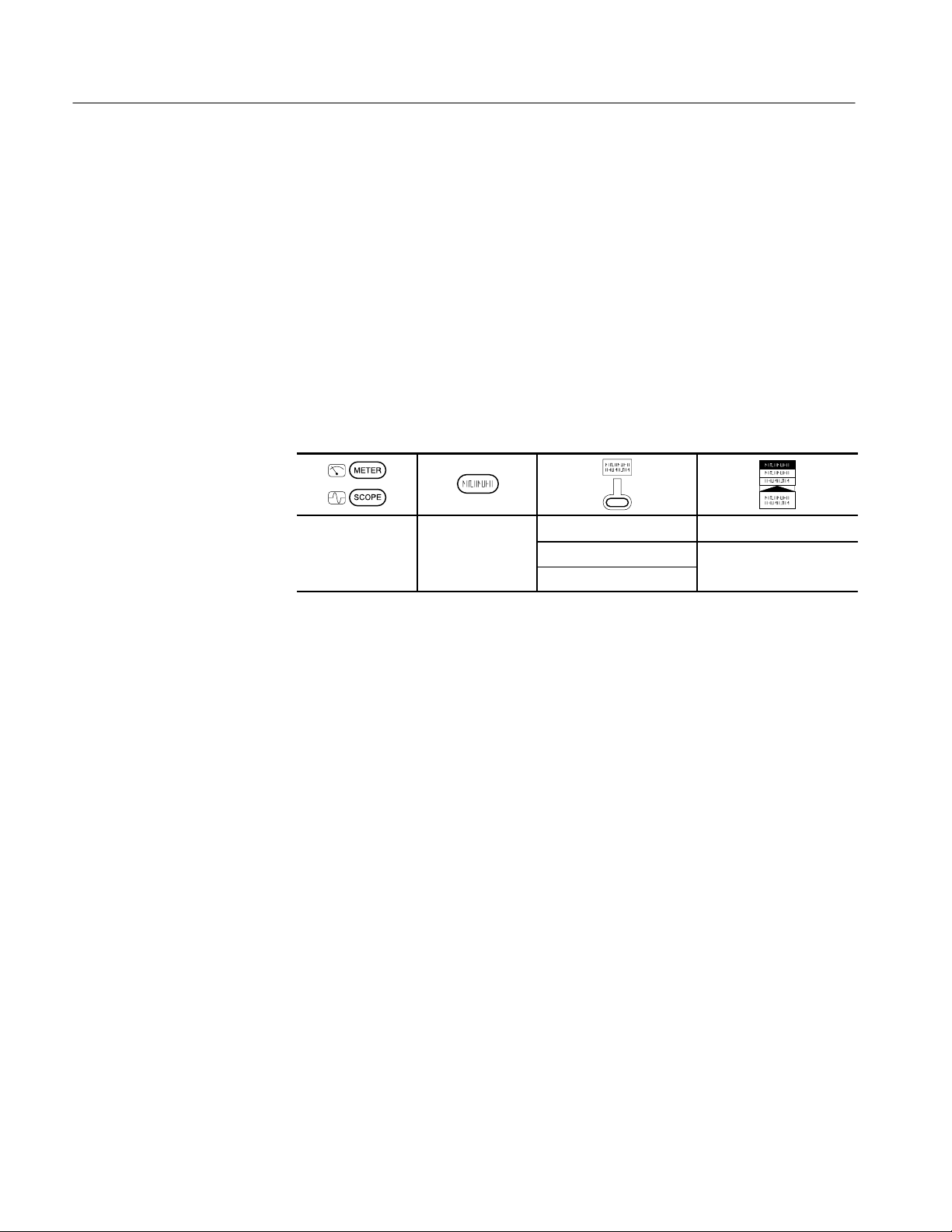
Adjustment Procedures
Y
—
Meter Adjustment
Procedure
After removing the adjustment-lockout jumper, use this procedure to adjust the
meter voltage references.
1. Turn on the TekScope instrument and let it warm up for at least ten minutes.
2. Connect the DC voltage source to the instrument as shown in the DC voltage
setup of Figure 5–3.
3. Set the DC voltage source amplitude to 400 mV.
4. Use the TekScope instrument setup below to start the meter adjustment
process. For each step, follow the specific instructions displayed by the
instrument to connect the correct signal source and confirm that you are
ready to proceed to the next step.
METER UTILIT
System Cal
Factory DMM
OK Factory Cal DMM
If any step in the procedure fails, the procedure terminates. Failure will result if
an incorrect signal source is connected. If this happens, you must start the
procedure over from the beginning.
Completing the
Adjustment Process
If the procedure completes successfully, a “Pass” message is displayed and the
new adjustment takes effect.
After adjusting the meter, continue with one of the following steps:
H Return to Oscilloscope Adjustment on page 5–5 to adjust the oscilloscope
voltage references.
H Proceed to Replacing the Adjustment-Lockout Jumper on page 5–11 to
protect the instrument from inadvertent readjustment.
5–10
THS 710 & THS 720 Service Manual

Replacing the Adjustment-Lockout Jumper
After you complete the adjustment process, you should reinstall the adjustmentlockout jumper to prevent inadvertent loss of calibrration. To replace the jumper,
repeat the procedure Accessing the Adjustment-Lockout Jumper on page 5–3.
However, in place of step 9, reinstall the jumper onto pins 1 and 2 as shown in
Figure 5–4.
Adjustment Procedures
Adjustment-lockout
jumper position
Figure 5–4: Relocating the adjustment-lockout jumper
This completes the adjustment procedure.
THS 710 & THS 720 Service Manual
5–11

Adjustment Procedures
5–12
THS 710 & THS 720 Service Manual


Maintenance
This chapter contains the information needed to do periodic and corrective
maintenance on the TekScope instrument. The following sections are included:
H Preparation refers you to important information contained elsewhere in this
manual.
H Preventing ESD provides general information on preventing damage to
internal modules when doing maintenance.
H Inspection and Cleaning provides procedures for inspecting the TekScope
instrument and cleaning its external and internal modules.
H Removal and Installation Procedures provide procedures for the removal and
installation of modules.
H Troubleshooting provides information for isolating failed modules.
H Repackaging Instructions provides packaging information for shipment or
storage.
Preparation
Preventing ESD
Only qualified personnel should perform service procedures. Read the Service
Safety Summary and the General Safety Summary before performing any service
procedures. Also refer to the chapter Operating Information for information
about using the TekScope instrument.
When performing any service which requires internal access to the TekScope
instrument, adhere to the following precautions to avoid damaging internal
modules and their components due to electrostatic discharge (ESD).
CAUTION. Static discharge can damage any semiconductor component in this
waveform analyzer.
1. Minimize handling of static-sensitive modules.
2. Transport and store static-sensitive modules in their static protected
containers or on a metal rail. Label any package that contains static-sensitive
modules.
THS 710 & THS 720 Service Manual
6–1

Maintenance
Inspection and Cleaning
3. Discharge the static voltage from your body by wearing a grounded antistatic
wrist strap while handling these modules. Do service of static-sensitive
modules only at a static-free work station.
4. Nothing capable of generating or holding a static charge should be allowed
on the work station surface.
5. Handle circuit boards by the edges when possible.
6. Do not slide the modules over any surface.
7. Avoid handling modules in areas that have a floor or work-surface covering
capable of generating a static charge.
This section describes how to inspect for dirt and damage, and how to clean the
TekScope instrument. Inspection and cleaning are done as preventive maintenance. Preventive maintenance, when done regularly, may prevent malfunctions
and enhance reliability.
General Care
Inspection and Cleaning
Procedures
Preventive maintenance consists of visually inspecting and cleaning the
TekScope instrument, and using general care when operating it. How often to do
maintenance depends on the severity of the environment in which the instrument
is used. A proper time to perform preventive maintenance is just before
adjustment of the instrument.
Protect the TekScope instrument from adverse weather conditions. The instrument is not waterproof.
Do not store or leave the instrument where the LCD display will be exposed to
direct sunlight for long periods of time.
The front and back covers help keep dust out of the TekScope instrument and
must be in place during normal operation.
CAUTION. To avoid damage to the TekScope instrument, do not expose it to any
sprays, liquids, or solvents.
Inspect and clean the TekScope instrument as often as operating conditions
require. The collection of dirt on internal components can cause them to overheat
and breakdown. Dirt acts as an insulating blanket, preventing efficient heat
dissipation. Dirt also provides an electrical conduction path
instrument failure, especially under high-humidity conditions.
that could cause an
6–2
THS 710 & THS 720 Service Manual

Maintenance
Inspection — Exterior. Inspect the outside of the TekScope instrument for
damage, wear, and missing parts. Instruments that appear to have been dropped
or otherwise abused should be checked thoroughly to verify correct operation
and performance. Immediately repair defects that could cause personal injury or
lead to further damage to the instrument.
Cleaning Procedure — Exterior. To clean the TekScope instrument exterior,
perform the following steps:
1. Remove loose dust on the outside of the instrument with a lint free cloth.
Use care to avoid scratching the clear plastic display filter.
2. Use a soft cloth or paper towel dampened with water to clean the instrument.
You can use a 75% isopropyl alcohol solution for more efficient cleaning.
CAUTION. To avoid damage to the surface of the TekScope instrument, do not use
any abrasive or chemical cleaning agents.
Inspection — Interior. During normal use, the TekScope instrument case seals the
internal components against common dust and dirt. However, if it appears that
the instrument may have been damaged or has been exposed to an unusually
dirty or wet environment, you should inspect and clean the interior.
To inspect and clean the interior, disassemble the instrument according to the
procedure Complete Disassembly on page 6–23.
Inspect the internal portions of the instrument for damage and wear using
Table 6–1 as a guide. Defects found should be repaired immediately.
T able 6–1: Internal inspection check list
Item Inspect For Repair Action
Front and Back
Cover
Hole Plugs, Gasket and Foam
Pads
Circuit boards Loose, broken, or corroded
Cracks or deformations.
Scratched lettering or display
filter. Loose connectors or
labels.
Misplaced or missing pieces. Relocate or replace defective pieces.
solder connections. Burned
circuit boards. Burned, broken,
or cracked circuit-run plating.
Repair or replace defective hardware.
Remove failed module and replace with a
new module.
THS 710 & THS 720 Service Manual
6–3

Maintenance
T able 6–1: Internal inspection check list (Cont.)
Item Repair ActionInspect For
Solder connections Cold solder or rosin joints. Resolder joint and clean with isopropyl
alcohol.
Wiring and cables Loose plugs or connectors.
Burned, broken, or frayed
wiring.
Firmly seat connectors. Repair or replace
modules with defective wires or cables.
Cleaning Procedure — Interior. To clean the TekScope instrument interior,
perform the following steps:
1. Blow off dust with dry, low-pressure, deionized air (approximately 9 psi).
2. Remove any remaining dust with a lint-free cloth dampened in isopropyl
alcohol (75% solution) and rinse with warm deionized water. (A cottontipped applicator is useful for cleaning in narrow spaces and on circuit
boards.)
STOP. If, after performing steps 1 and 2, a module is clean upon inspection, skip
steps 3 and 4. Proceed with step 5.
If steps 1 and 2 do not remove all the dust or dirt, all modules in the instrument
except the Display Module may be spray washed using a solution of 75%
isopropyl alcohol. Proceed with step 3.
3. Spray wash dirty parts with the 75% isopropyl alcohol solution and wait
60 seconds for the majority of the alcohol to evaporate.
6–4
4. Use hot (49_ C to 60_ C / 120_ F to 140_ F) deionized water to thoroughly
rinse the parts.
5. Dry all parts with low-pressure, deionized air.
6. Dry all components and assemblies in an oven or drying compartment using
low-temperature (52_ C to 66_ C / 125_ F to 150_ F) circulating air.
Lubrication. There is no periodic lubrication required for the TekScope instrument.
THS 710 & THS 720 Service Manual

Removal and Installation Procedures
This section describes how to remove and install the major mechanical and
electrical modules. It provides the following information:
H List of Modules on page 6–5 describes where to locate a list of replaceable
modules.
H Summary of Procedures on page 6–6 lists the procedures for removal and
installation of modules.
H Tools Required on page 6–7 describes the tools needed to perform the
procedures.
H Tilt Stand, on page 6–8, begins a series of procedures that describe the
removal and installation of modules.
Maintenance
Preparation
List of Modules
Please read the following warning statement. Then read the following general
instructions before removing a module.
WARNING. Only qualified personnel should perform service procedures. Before
doing this or any other procedure in this manual, read the General Safety
Summary and Service Safety Summary found at the beginning of this manual.
Also, to prevent possible injury to service personnel or damage to electrical
components, read Preventing ESD on page 6–1.
1. Read the Summary of Procedures on page 6–6 to understand which
procedure to use to access a given module. Then read Tools Required on
page 6–7 for a list of tools needed to remove and install modules in the
TekScope instrument.
2. If you are disassembling the TekScope instrument for cleaning, refer to the
Inspection and Cleaning procedure on page 6–2 for cleaning instructions.
The Mechanical Parts List chapter provides a list of all replaceable modules.
Any electrical or mechanical module, assembly, or part listed in the parts list is
referred to as a module.
THS 710 & THS 720 Service Manual
6–5

Maintenance
Summary of Procedures
Table 6–2 lists the removal and installation procedures in order of increasing
complexity.
T able 6–2: Removal and installation procedures
Procedure Modules Accessed Begins on Page
Tilt Stand Tilt stand 6–8
Front-Panel Label Front-panel label 6–10
Front Cover Front cover
Display shield
Switch mat
Gasket
Handle
Battery door
Screws
Display Module Display module
Inverter board
Back Cover DC power hole plug
6–1 1
6–16
6–19
I/O port hole plug
Back cover / back label /
battery contact assembly
Complete Disassembly Chassis / BNC connectors /
banana jacks
Main board
Switch flex-circuit assembly
Display cable
Inverter board cable
Foam pad set
2
Some pieces in the foam pad set are accessed by the Front Cover and Back Cover
procedures.
2
6–23
6–6
THS 710 & THS 720 Service Manual

Maintenance
Tools Required
You will need the following tools to remove and replace all the modules in the
TekScope instrument.
H Torque-limiting screwdriver, 12 in ⋅ lb (1.3 N ⋅ m) range with Torx T-15 tip
H Screwdriver with
H Screwdriver with
1
@
inch flat blade
4
1
@
inch flat blade
8
H Needle-nose pliers
H Sharp knife (X-ACTO knife or equivalent)
THS 710 & THS 720 Service Manual
6–7

Maintenance
Tilt Stand
1
@
You will need a
inch flat-bladed screwdriver to remove the tilt stand.
4
STOP. You do not have to remove the tilt stand to access internal modules. In
most cases, you do not have to remove the tilt stand to clean the TekScope
instrument exterior.
Removal. Use this procedure to remove a defective tilt stand.
1. Place the TekScope instrument face down on a soft surface (such as an
anti-static mat).
2. Insert the
1
@
inch flat-bladed screwdriver into the gap between the tilt stand
4
and instrument case as shown in Figure 6–1.
3. Twist the screwdriver gently to release one side of the tilt stand from the
instrument case. Take care not to damage the case.
6–8
Figure 6–1: Removing the tilt stand
THS 710 & THS 720 Service Manual

Maintenance
Installation. Use this procedure to install a new tilt stand.
1. Orient the tilt stand to the back of the instrument case with the hinge pins
toward the top and the side bump toward the handle.
2. Insert one hinge pin into its socket and place the other into the cavity in the
back of the instrument case as shown in Figure 6–2.
3. Rotate the tilt stand to slide the second hinge pin upward and into its socket.
1
Insert hinge pin into the socket.
2
Rotate the tilt stand to slide the
second hinge pin into its socket.
Figure 6–2: Installing the tilt stand
THS 710 & THS 720 Service Manual
6–9

Maintenance
Front-Panel Label
You will need a sharp knife and needle-nose pliers to remove a defective
front-panel label.
CAUTION. Removal of a front-panel label will destroy it. Do not remove it unless
it is defective and needs to be replaced.
Removal. Use this procedure to remove a defective front-panel label.
1. Use the sharp knife to pry up a corner of the label.
2. Use the needle-nose pliers to peel the label off.
Installation. Use this procedure to install a new front-panel label in either a new
or the existing front cover.
1. Peel the paper off the back side of the new label.
2. Handling the label by its edges only, align it with the recess in the front
cover as shown in Figure 6–3.
3. When properly aligned, press the new label into place.
Front-panel label
Recess in the front cover
Figure 6–3: Installing a new front-panel label
6–10
THS 710 & THS 720 Service Manual

Maintenance
Front Cover
You will need a torque-limiting Torx T-15 screwdriver, needle-nose pliers, and
sharp knife to remove the front cover and other immediately accessible modules.
CAUTION. Attempting to remove the display shield from the front cover will likely
destroy both pieces. If one or the other are defective, both must be replaced.
Removal. Use this procedure to remove the front cover and access the handle,
switch mat, battery door, and gasket.
1. Disconnect all probes, cables, or meter leads from the instrument.
2. Disconnect the AC adapter, open the battery door, and remove the battery.
3. Place the TekScope instrument face down on a soft surface (such as an
anti-static mat).
4. Use the Torx T-15 screwdriver to remove the four screws that hold the case
together.
5. Holding the case together, pick it up and place it back side down on a soft
surface.
6. As you lift the front cover off the instrument, press the buttons as necessary
to prevent the switch mat from coming off with the front cover.
7. To remove the handle, slip it off its guides.
8. To remove the switch mat, lift it off the switch flex-circuit assembly. Place it
button-side down on a clean surface.
CAUTION. To avoid contamination of switch contacts, do not touch the carbon
contacts on the switch flex-circuit assembly or on the back side of the switch
mat.
9. To remove the battery door, use the needle-nose pliers to slip the retaining
tether off of the post inside the instrument case as shown in Figure 6–4.
THS 710 & THS 720 Service Manual
6–11
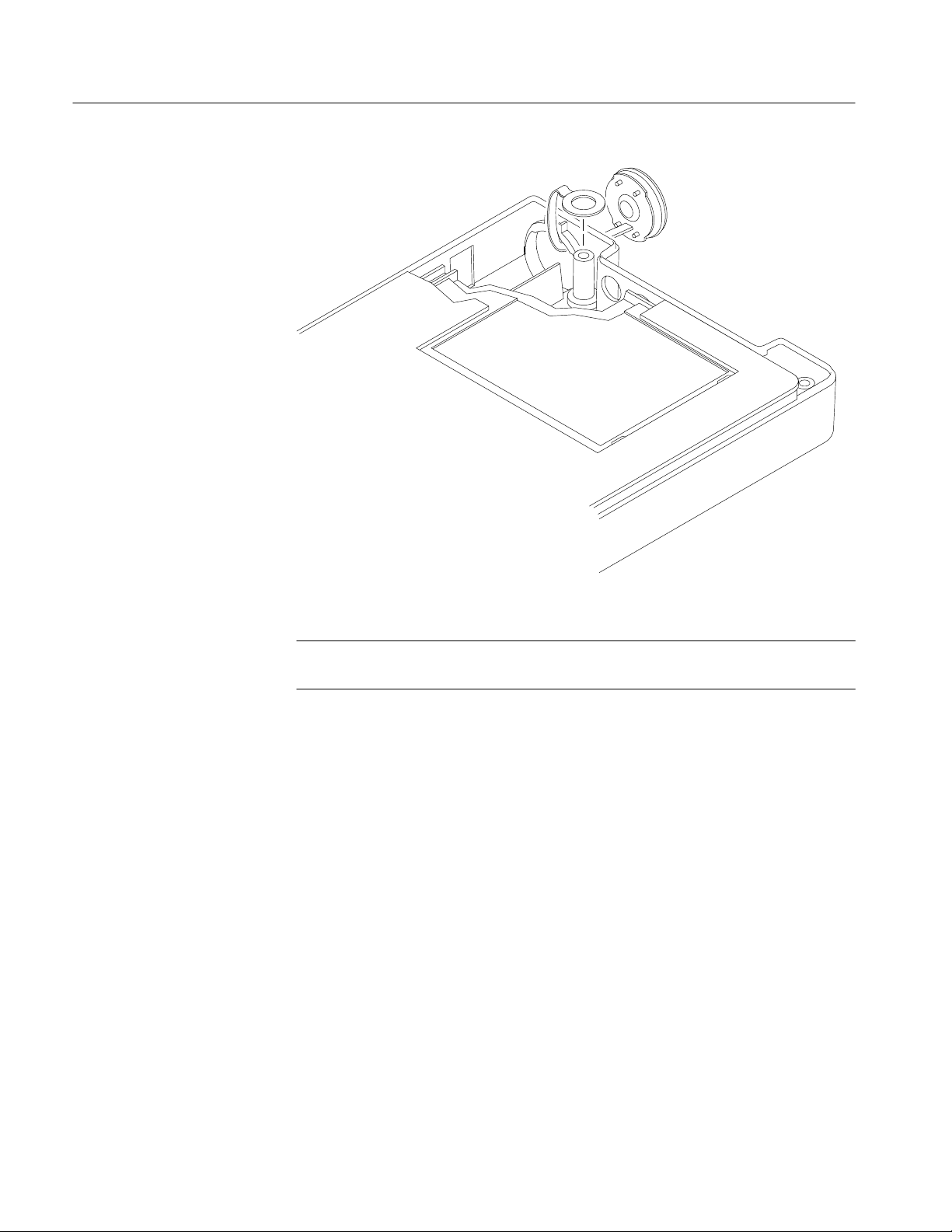
Maintenance
Figure 6–4: Removing the battery door
NOTE. In most cases, the gasket does not have to be removed from the front cover
for interior cleaning.
10. To remove the gasket from the front cover, use the needle-nose priers to lift
it out of the groove in the front cover, starting with the accessible tail at the
bottom of the front cover.
Installation. Use this procedure to install the battery door, switch mat, handle,
gasket, and front cover.
1. Place the TekScope instrument back side down on a soft surface (such as an
anti-static mat).
2. To install the battery door, pass the retaining tether through the battery
opening from the outside and then use the needle-nose pliers to slip the
retaining strap onto the post (see Figure 6–4).
3. To install the switch mat, place it (contact side down) on the switch
flex-circuit assembly. The five rubber guideposts fit into holes in the circuit
board.
6–12
THS 710 & THS 720 Service Manual

Maintenance
4. If you are installing a new front cover, follow these steps to assemble it
before installation. Refer to Figure 6–5.
a. Install a new label using the procedure on page 6–10.
b. Install a new display shield into the inside of the new front cover.
Remove the backing paper from the adhesive on the display shield, align
it over the two diagonal posts, and then press it into place. The blue
border should be even when viewed from the face of the front cover.
c. Install new foam pad as shown in Figure 6–5.
Display shield
Foam pad
Figure 6–5: Assembling a new front cover
THS 710 & THS 720 Service Manual
Front cover
d. Install a new gasket into the groove around the edge of the front cover.
As shown in Figure 6–6, start the gasket at the bottom of the cover
leaving a short (
into place around the rim with the
1
@
inch) tail through the slot. Carefully press the gasket
8
1
@
inch flat-bladed screwdriver. To
8
finish the installation, overlap the starting point and then pass the end of
the gasket through the remaining slot. Trim the ending tail to
1
@
8
inch
length with the sharp knife.
6–13

Maintenance
Gasket material
Front cover
Trim tails to
Overlap gasket material
1
@
inch
8
Figure 6–6: Installing the gasket
5. Slip the handle into the guides of the back cover as shown in Figure 6–7.
6. Place the front cover assembly onto the instrument. Taking care not to pinch
the handle, align it into the guides in the front cover. Align the buttons so
they all protrude through the holes in the front cover.
6–14
7. Holding the case together, pick it up and place it front side down on a soft
surface.
THS 710 & THS 720 Service Manual
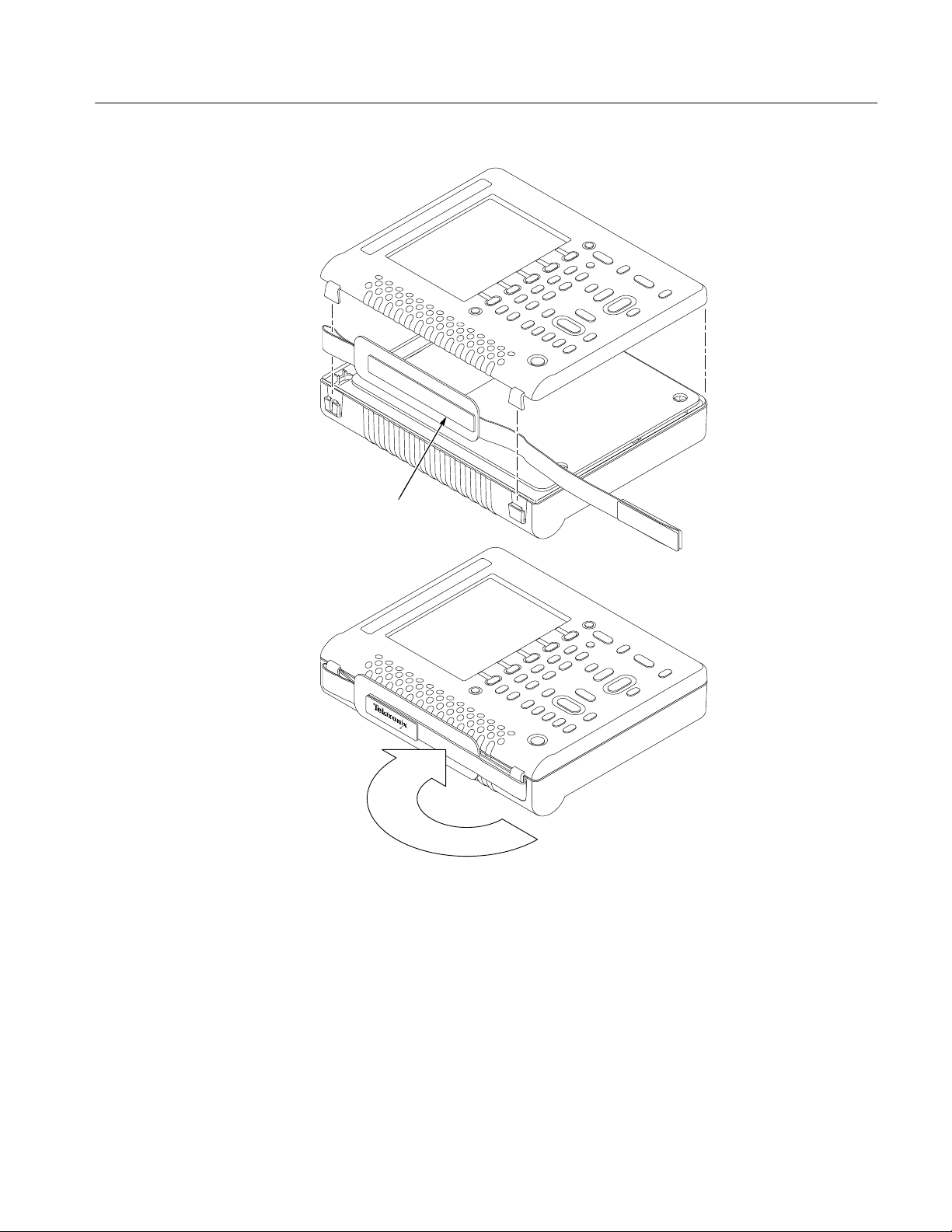
Velcro strip
Maintenance
Figure 6–7: Installing the handle
THS 710 & THS 720 Service Manual
Fold end of handle over
6–15

Maintenance
Display Module
CAUTION. To avoid cross-threading or cutting new threads with the screws,
carefully follow the procedure in the next step.
8. To install the four screws, follow these steps:
a. Place the screws into their holes in the back cover.
b. Using the torque-limiting Torx T-15 screwdriver, slowly turn each
screw backward (counterclockwise) until you feel the thread drop and
then gently tighten the screw (turn clockwise) into the existing thread.
c. When all four all screws are in, hold a corner of the case together firmly
to compress the gasket while tightening its screw until snug. Repeat for
the other corners. Do not overtighten the screws (12 in ⋅ lbs or 1.m N ⋅ m
maximum torque).
9. Replace the battery as shown on page 2–2, and then close the battery door.
1
@
You will need a
inch flat-bladed screwdriver to remove the display module
8
and inverter board.
Removal. First remove the front cover and switch mat using the procedure on
page 6–11. Then, use the following procedure to remove the display module and
inverter board.
1. Fold the switch flex-circuit assembly toward you to expose the display
module and inverter board.
CAUTION. To avoid scratching the surface of the display module, do not let it
touch any hard object.
The display module surface may scratch easily. To clean it, first try pressurized
air. If a soft cloth is required to clean it, use very light pressure.
2. To remove the inverter board, unplug the input and output connectors and
then lift the inverter board off the two guideposts. You may want to use the
1
@
inch flat-bladed screwdriver to help release the connectors from their
8
sockets.
3. To remove the display module, follow these steps:
a. Disconnect the cable from the display module to the inverter board, if it
is not already disconnected.
6–16
b. Lift the right side of the display module out of the chassis and fold the
display module to the left, as shown in Figure 6–8.
THS 710 & THS 720 Service Manual

Display cable connector
Maintenance
Display module
Inverter board
Spring
Switch flex-circuit board
Figure 6–8: Removing the display module
c. Using the
d. When the connector is open, slip the display cable out of the connector
THS 710 & THS 720 Service Manual
1
@
inch flat-bladed screwdriver, carefully open the display-
8
cable connector as shown in Figure 6–9.
to free the display module.
6–17

Maintenance
Contact side of cable
Figure 6–9: Opening the display cable connector
Installation. Use this procedure to install the display module and inverter board.
1. Open the display-cable connector on the back of the display module.
2. Hold the display module upright as shown in Figure 6–8.
1
@
3. Insert the display cable into its connector and then use the
inch flat-bladed
8
screwdriver to close the connector. Check that the display cable is fully
inserted into the connector.
4. Fold the display module back into the chassis and seat it between the foam
pads.
5. Plug the cable from the display module into the inverter board and then route
the cable in the channels as shown in Figure 6–10.
6. Place the inverter board into its cavity over the guideposts in the chassis.
7. Reconnect the connector to the bottom of the inverter board and route the
wires as shown in Figure 6–10.
8. If you just installed a new display module, peel off the protective plastic
sheet.
9. Fold the switch flex-circuit assembly back over the display module and
inverter board.
6–18
10. Install the switch mat and front cover using the procedure on page 6–12.
THS 710 & THS 720 Service Manual

Inverter output
connector
Inverter board
Maintenance
Display module
Route cable
through channels
Back Cover
Inverter input
connector
Route cable
through channel
Route cable
under clip
Figure 6–10: Routing cables to the inverter board
1
@
You will need a
inch flat-bladed screwdriver and needle-nose pliers to remove
8
the chassis assembly and hole plugs from the back cover.
NOTE. The back labels and battery contacts are an integral part of the back
cover. If any of these parts are defective, the back cover must be replaced.
Removal. First remove the front cover and switch mat using the procedure on
page 6–11. Then, use the following procedure to remove the chassis assembly.
1. Place the instrument back-side down on a soft surface.
2. Lift the battery connector, located on the handle-side of the chassis, off its
retaining pins and disconnect the connector.
3. Insert the
THS 710 & THS 720 Service Manual
1
@
inch flat-bladed screwdriver between the back cover and chassis
8
at the location shown in Figure 6–11.
6–19

Maintenance
4. Carefully lift the bottom of the chassis out of the back cover. As the chassis
assembly comes out, pull it toward you to back the BNC connectors out of
their holes in the back cover.
Figure 6–11: Lifting the chassis
5. When the chassis is free from the back cover, set it aside with the main board
facing down on a soft, static-free surface.
6. To remove a defective DC power hole plug or I/O port hole plug, follow
these steps:
a. From the outside of the back cover, pull on the hole plug.
1
@
b. From the inside of the back cover, use the
inch flat-bladed screwdriver
8
to work each retaining tab out of its hole in the back cover.
Installation. Use this procedure to install the hole plugs and chassis assembly into
the back cover.
1. To install a new hole plug, insert the retaining tabs into their holes in the
back cover. While pushing on the plug from the outside, pull gently on the
tabs from the inside with the needle-nose pliers until they lock into place.
2. To install the chassis assembly into the back cover, follow these steps:
a. If the instrument was completely disassembled, check that the chassis is
properly assembled.
6–20
b. Check that all foam pads inside the back cover are correctly installed.
Refer to Figure 6–12 for the correct locations.
THS 710 & THS 720 Service Manual

Install DC power
hole plug
Maintenance
Install foam pads
Install foam pad
Install I/O port
hole plug
Install foam pad
Install foam pads
Figure 6–12: Foam pad and hole plug locations on the back cover
c. Place the back cover on a soft surface with the BNC connector openings
facing away from you.
d. Dress the battery wires to the left side of the back cover to provide
clearance for the chassis.
e. While inserting the BNC connectors into their openings, lower the
chassis into the back cover.
f. Reconnect the battery wire connector and press it onto its retaining pins.
Check that the polarity of the connector is correct. Dress the wires into
the channel on the chassis as shown in Figure 6–13.
3. Install the switch mat and front cover using the procedure on page 6–12.
THS 710 & THS 720 Service Manual
6–21

Maintenance
Retain connectors
between pins
Locate ferrite
bead in cavity
Figure 6–13: Routing the battery wires
Dress wires from battery
pack through slots
6–22
THS 710 & THS 720 Service Manual
 Loading...