


xx
THS3000 Series
ZZZ
Oscilloscopes
User Manual
*P077060700*
077-0607-00


xx
THS3000 Series
ZZZ
Oscilloscopes
User Manual
www.tektronix.com
077-0607-00

Copyright © Tektronix. All rights reserved. Licensed software products are owned by Tektronix or its subsidiaries
or suppliers, and are protected by national copyright laws and international treaty provisions.
Tektronix products are covered by U.S. and foreign patents, issued and pending. Information in this publication
supersedes that in all previously published material. Specifications and price change privileges reserved.
TEKTRONIX and TEK are registered trademarks of Tektronix, Inc.
Contacting Tektronix
Tektronix, Inc.
14150 SW Karl Braun Drive
P.O. Box 5 0 0
Beaverto
USA
For product information, sales, service, and technical support:
n, OR 97077
In North America, call 1-800-833-9200.
Worl dwid e, visi t www.tektronix.com to find contacts in your area.

Warranty
Tektronix warrants that this product will be free from defects in materials and workmanship for a period of three
(3) years from the date of shipment. If any such product proves defective during this warranty period, Tektronix, at
its option, either will repair the defective product without charge for parts and labor, or will provide a replacement
in exchange for the defective product. Parts, modules and replacement products used by Tektronix for warranty
work may be n
the property of Tektronix.
ew or reconditioned to like new performance. All replaced parts, m odules and products become
In order to o
the warranty period and make suitable arrangements for the performance of service. Customer shall be responsible
for packaging and shipping the defective product to the service center designated by Tektronix, with shipping
charges prepaid. Tektronix shall pay for the return of the product to Customer if the shipment is to a location within
the country in which the Tektronix service center is located. Customer shall be responsible for paying all shipping
charges, duties, taxes, and any other charges for products returned to any other locations.
This warranty shall not apply to any defect, failure or damage caused by improper use or improper or inadequate
maintenance and care. Tektronix shall not be obligated to furnish service under this warranty a) to repair damage
result
b) to repair damage resulting from improper use or connection t o incompatible equipment; c) to repair any damage
or malfunction caused by the use of non-Tektronix supplies; or d) to service a product that has been modified or
integrated with other products when the effect of such modification or integration increases the time or difficulty
of servicing the product.
THIS WARRANTY IS GIVEN BY TEKTRONIX WITH RESPECT TO THE PRODUCT IN LIEU OF ANY
OTHER WARRANTIES, EXPRESS OR IMPLIED. TEKTRONIX AND ITS VENDORS DISCLAIM ANY
IMPLIED WARRANTIES OF MERCHANTABILITY OR FITNESS FOR A PARTICULAR PURPOSE.
TRONIX' RESPONSIBILITY TO REPAIR OR REPLACE DEFECTIVE PRODUCTS IS THE SOLE
TEK
AND EXCLUSIVE REMEDY PROVIDED TO THE CUSTOMER FOR BREACH OF THIS WARRANTY.
TEKTRONIX AND ITS VENDORS WILL NOT BE LIABLE FOR ANY INDIRECT, SPECIAL, INCIDENTAL,
OR CONSEQUENTIAL DAMAGES IRRESPECTIVE OF WHETHER TEKTRONIX OR THE VENDOR HAS
ADVANCE NOTICE OF THE POSSIBILITY OF SUCH DAMAGES.
[W4 – 15AUG04]
btain service under this warranty, Customer must notify Tektronix of the defect before the expiration of
ing from attempts by personnel other than Tektronix representatives to install, repair or service the product;


Table of Contents
General Safety Summary ......................................................................................... vi
Preface .............................................................................................................. ix
Where To Find More Information ........................................................................... x
Terms Used In This Manual .................................................................................. x
Getting Started
Introduction ....................................................................................................... 1-1
Product Description..................................... ................................ ..................... 1-1
Front Panel Navigation........................... ................................ ........................... 1-2
Initial Setup. . ..... . ..... . ..... . ..... . ..... . ..... . ... . . . .... . . .... . . .... . . .... . . .... . . .... . . .... . ..... . ..... . .. 1-9
Restore Factory Default Settings.................. .................................. ..................... 1-12
Tilt Stand, Hanging Hook, and Kensington® Lock.................................................... 1-13
Operating Basics
Operating Basics.................................................................................................. 2-1
Input Connections .... ................................ ................................ ....................... 2-1
About Floating Measurements ............................................................................. 2-2
Connect Probes and Leads......... ................................ ................................ ......... 2-4
Select an Input Channel ................................................................................... 2-12
Adjust the Probe Type Settings. . ..... . .... . ..... . ..... . ... . . ..... . ..... . .... . ..... . ..... . ... . . ..... . ..... 2-13
Display an Unknown Signal with Autoset or AutoRange™.......................................... 2-13
Automatic Measurements...................... .................................. ......................... 2-15
Stop the Display .... ................................ .................................. ..................... 2-18
Average, Persistence, and Glitch Capture . ..... ..... . ..... . ..... . .... . . .... . ..... . ..... . ... . . ..... . ..... 2-19
Acquire Waveforms ....................................................................................... 2-22
Pass-Fail Testing ........................................................................................... 2-30
Functional Overview
Recorder Functions............ .................................. ................................ ................. 3-1
Plot Measurements Over Time (TrendPlot™)................... ................................ ......... 3-1
Record Waveforms In Deep Memory (Scope Roll Mode) ............. ................................ . 3-3
Analyze Waveforms.............................................................................................. 3-6
Use Replay ................................................................................................... 3-6
Use Zoom..................................................................................................... 3-7
Use Cursors................................ ................................ ................................ ... 3-9
THS3000 Series Oscilloscopes User Manual i

Table of Contents
Trigger Functi
Save and Recall................................................................................................. 3-25
Troubleshooting................................................................................................. 3-33
Appendices
Appendix A:
Introduction.................................................................................................. A-1
General Specifications........................................ ................................ .............. A-1
Recorder Specifications .................... .................................. .............................. A-6
Zoom, Data Log, and Cursors Specifications...... ................................ ...................... A-6
Miscellaneous Specifications ................ .................................. ............................ A-7
Safety S
Probe Specifications .... ................................ .................................. ................ A-12
Appendix B: Connect The Instrument To A Computer ..................................................... B-1
USB Ports............................ .................................. ................................ ...... B-2
Install USB Drivers....................... ................................ .................................. B-3
Appendix C: Probe Compensation and Compatible Maximum Voltages ..................... ............ C-1
Compe
Compatible Probe Maximum Voltages ............................... .................................. .. C-3
Appendix D: Battery Pack.............................. ................................ ........................ D-1
Save Battery Life ........................................................................................... D-1
Charge the Batteries .................... .................................. ................................ .. D-2
Appendix E: Maintenance and Cleaning................ ................................ ...................... E-1
intaining the Instrument .............. ................................ .................................. E-1
Ma
Cleaning ..................................................................................................... E-1
Storage ... ................................ .................................. ................................ .. E-1
ons............................................................................................... 3-14
Specifications ...... .................................. ................................ ............ A-1
pecifications ..................................................................................... A-10
nsate Voltage Probes ............................................................................... C-1
Index
ndex
I
ii THS3000 Series Oscilloscopes User Manual

List of Figures
Figure 1-1: Instrument front panel............. .................................. ............................... 1-3
Figure 1-2: Rising edge of square wave ..................................................................... 1-12
Figure 1-3: Tilt stand and location of Kensington® Lock .............. ................................ ... 1-13
Figure 1-4: How to use the hanging hook handle........................................................... 1-14
Figure 1-5: How to use the hanging strap handle........................................................... 1-15
Figure 2-1: Top panel input connectors ........................................................................ 2-1
Figure 2-2: Isolated input architecture ......................................................................... 2-2
Figure 2-3: Common-reference input architecture......................... .................................. . 2-3
Figure 2-4: Parasitic capacitance between probes, instrument, and environment...... ................... 2-5
Figure 2-5: Parasitic capacitance between analog and digital reference ................ ................... 2-6
Figure 2-6: Correct connection of reference leads........................... ................................ . 2-6
Figure 2-7: Wrong connection of reference leads............................................................. 2-7
Figure 2-8: Making voltage probe connections on four channels. ......... ................................. 2-8
Figure 2-9: Voltage probe connection using a ground spring............................... ................. 2-9
Figure 2-10: Connections using hook tips and alligator clip grounding.. . ..... . ..... . ..... . ... . . . .... . . . 2-10
Figure 2-11: Probe tip ground ring ........................................................................... 2-11
Figure 2-12: Display with Autoset .................. ................................ ......................... 2-14
Figure 2-13: Display with AutoRange™ ....................... ................................ ............. 2-15
Figure 2-14: Hz and V peak-peak as measurements................................. ....................... 2-17
Figure 2-15: Frozen (stopped) display .................. .................................. ................... 2-18
Figure 2-16: Live (running) display......... ................................ ................................. 2-19
Figure 2-17: Using persistence to observe dynamic signals .............. ................................. 2-21
Figure 2-18: FFT measurement ............................... .................................. ............. 2-27
Figure 3-1: RECORDER REPLAY main menu .. . ..... . ..... . ..... . .... . . .... . ..... . ..... . ..... . .... . ..... . . 3-1
Figure 3-2: TrendPlot™ measurement......................................................................... 3-2
Figure 3-3: Recording waveforms using Scope Roll Mode ................................................. 3-3
Figure 3-4: Zooming in on a Waveform ...... ................................ ................................. 3-8
Figure 3-5: Voltage measurement with horizontal cursors................................................. 3-10
Figure 3-6: Time measurement with vertical cursors....................................................... 3-12
Figure 3-7: Risetime measurement using cursors.............................. ............................. 3-13
Figure 3-8: Screen with all trigger information ............................................................. 3-17
Figure 3-9: Trigger delay or pretrigger view ........................... ................................ ..... 3-18
Figure 3-10: Making a single shot measurement .............. ................................ ............. 3-21
Figure 3-11: N-Event triggering .............................................................................. 3-22
Figure 3-12: Trigger on NTSC video signal field 1........................................ ................. 3-23
Figure 3-13: Pulse width triggering .......................................................................... 3-24
THS3000 Series Oscilloscopes User Manual iii

Table of Contents
Figure A-1: Inp
Figure A-2: Maximum voltage between oscilloscope references, and between oscilloscope references and
earth ground ......... .................................. ................................ ..................... A-11
Figure B-1: Instrument USB connections .............. ................................ ...................... B-2
Figure C-1: Compensating voltage probes ................................................................... C-2
ut voltage versus frequency ................................................................. A-11
iv THS3000 Series Oscilloscopes User Manual

List of Tables
Table i: Product documentation................................................................................... x
Table 2 -1: C
Table 2-2: Pixel colors description ........................................................................... 2-30
Table 3-1: Trigger types ...................... ................................ ................................. 3-15
Table 3-2: Internal memory ................................................................................... 3-25
Table A-1: Record Length (Samples/points per input)...................... ................................ A-1
Table A-2: Oscilloscope Inputs . . ..... . ... . . ..... . ..... . ..... . ..... . .... . . .... . ..... . ..... . ..... . ..... . ..... . . A-2
Table A-3
Table A-4: Zoom, Data Log, and Cursors .................................................................... A-6
Table A-5: Display ...................... ................................ ................................ ........ A-7
Table A-6: Power .............................. ................................ ................................ .. A-7
Table A-7: Probe Calibration Output Signal ................. ................................ ................ A-8
Table A-8: Memory ............. ................................ ................................ ................ A-8
Table
Table A-10: Mechanical .. .................................. ................................ .................... A-9
Table A-11: Environmental......................................... .................................. .......... A-9
Table A-12: Safety specifications.................................. ................................ .......... A-10
Table A-13: THP0301 Voltage Probe ................. ................................ ...................... A-12
Table C-1: Compatible probe maximum voltages ......... ................................ .................. C-3
omparison of averaged versus nonaveraged waveforms ................... ................. 2-20
: Recorder............................................................................................. A-6
A-9: Interface Ports ...................................................................................... A-9
Table of Contents
THS3000 Series Oscilloscopes User Manual v

General Safety Summary
General Safet
To Avoid Fire or Personal
Injury
ySummary
Review the fo
this product or any products connected to it.
To avoid pot
Only qualified personnel should perform service procedures.
While using this product, you may need to access other parts of a larger system.
Read the safety sections of the other component manuals for warnings and
cautions r
Use proper power cord. Use only the power cord specified for this product and
certified for the country of use.
Connect and disconnect properly. Do not connect or disconnect probes or test
leads while they are connected to a voltage source.
Connect and disconnect properly. Connect the probe output to the measurement
instrument before connecting the probe to the circuit under test. Connect the
probe reference lead to the circuit under test before connecting the probe input.
Disconnect the probe input and the probe reference lead from the circuit under test
before disconnecting the probe from the measurement instrument.
llowing safety precautions to avoid injury and prevent damage to
ential hazards, use this product only as specified.
elated to operating the system.
Observe all terminal ratings. To avoid fire or shock hazard, observe all ratings
and markings on the product. Consult the product manual for further ratings
ormation before making connections to the product.
inf
Do not apply a potential to any terminal, including the common terminal, that
ceeds the maximum ratingofthatterminal.
ex
Power disconnect. The power cord disconnects the product from the power source.
notblockthepowercord;itmustremain accessible to the user at all times.
Do
Do not operate without covers. Do not operate this product with covers or panels
emoved.
r
Do not operate with suspected failures. If you suspect that there is damage to this
product, have it inspected by qualified service personnel.
Avoid exposed circuitry. Do not touch exposed connections and components when
power is present.
Replace batteries properly. Replace batteries only with the specified type and
rating.
Use proper AC adapter. Use only the AC adapter specified for this product.
vi THS3000 Series Oscilloscopes User Manual

General Safety Summary
TermsinThisManual
Symbols and Terms on the
Product
Do not operate i
Do not operate in an explosive atmosphere.
Keep product surfaces clean and dry.
These terms
WAR NI NG . Warning statements identify conditions or practices that could result
in injury or loss of life.
CAUTION. Caution statements identify conditions or practices that could result in
damage to this product or other property.
These terms may appear on the product:
DANGER
the marking.
WARNI
read the marking.
CAUT
n wet/damp conditions.
may appear in this manual:
indicates an injury hazard immediately accessible as you read
NG indicates an injury hazard not immediately accessible as you
ION indicates a hazard to property including the product.
The following symbol(s) may appear on the product:
THS3000 Series Oscilloscopes User Manual vii

General Safety Summary
viii THS3000 Series Oscilloscopes User Manual

Preface
Preface
This manual c
THS3014 Handheld Oscilloscopes. It consists of the following chapters:
The Getting
panel navigation, button menus, and provides installation instructions and a
functional check procedure. (See page 1-1.)
The Operating Basics chapter provides information about operating the front
panel, what functions each menu accesses, how to connect to inputs, and
using the tilt and security features. (See page 2-1.)
The Functional Overview chapter provides an overview of how the various
functions and features of the instrument operate. (See page 3-1.)
The Appendix A: Specifications chapter includes electrical, environmental,
physical specifications for the instrument, and certifications and compliances.
(See page A-1.)
The Appendix B: Connect The Instrument to a Computer chapter provides
procedures for connecting the instrument to a computer and installing USB
drivers and OpenChoice™ Desktop software. (See page B-1.)
The Appendix C: Probe Calibration and Compatible Maximum Voltages
chapter provides calibration and other probe information. (See page C-1.)
The Appendix D: Battery Pack chapter provides information about how to
preserve battery life and charge the battery. (See page D-1.)
ontains operating information for the Tektronix THS3024 and
Started chapter briefly describes features of the instrument, front
The Appendix E: Maintenance and Cleaning chapter describes how to take
care of the instrument. (See page E-1.)
THS3000 Series Oscilloscopes User Manual ix

Preface
WhereToFindM
ore Information
You c a n find more information about your instrument in the following
documents. These documents can be found on the Tektronix Web site at
www.tektron
ix.com/manuals, on the Product Documentation CD that shipped
with your instrument, or both.
Table i: Product documentation
To read about Use these documents
Compliance, safety, standard
and optional equipment and
accessor
battery installation
Operation, configuration,
specifications, and instrument
capabil
Performance verification
procedures
Declassification and security Declassification and Security Instructions available for download at www.tektronix.com/manuals
ies, power on and off,
ities
Installation and Safety Instructions available printed, on the Product Documentation CD that
shipped with your instrument, and for download at www.tektronix.com/manuals.
User manual (this manual) available in English, German, French, Spanish, Italian,
Portuguese, Russian, Korean, Japanese, Simplified Chinese, and Traditional Chinese on
the Prod
www.tektronix.com/manuals.
Performance Verification manual available on the Product Documentation CD that shipped with
your instrument, and for download at www.tektronix.com/manuals.
uct Documentation CD that shipped with your instrument and for download at
Terms Used In This Manual
ated, electrically floating. The terms “isolated” or “electrically floating” are
Isol
used in this manual to indicate a measurement in which the product input BNC is
connected to a voltage different from earth ground.
Working voltage. Voltage ratings that are mentioned in the warnings in this
manual are given as limits for “working voltage”. They represent V AC RMS
0-60 Hz) for AC sine wave applications and as V DC for D C applications.
(5
x THS3000 Series Oscilloscopes User Manual

Getting Started


Introduction
Product Description
In addition to a product and feature description, this chapter covers the following
topics:
How to perform a quick functional check, install and compensate passive
probes, compensate the signal p ath, and set the time and date
How to u se the front panel and menu system
How to identify the instrument controls and connectors
This chapter provides information about instrument setup, menus, and basic
functions. This introduction does not cover all of the capabilities of the instrument
but gives basic examples to show how to use the menus and perform basic
operations.
The Tektronix THS3024 and THS3014 Four Channel Handheld Oscilloscopes are
rugged, handheld oscilloscopes ideal for the lab and field.
General Features
Key Features
Four fully isolated input channels
Volts, Time, Frequency and Watts cursor measurements
Bright, high contrast QVGA color display
7 hour battery operation or external AC/DC adapter power
21 automatic measurements
Comprehensive data logging and analysis capabilities
USB 2.0 device and host s upport for exchanging images, waveforms, and
settings
Tektronix OpenChoice® Desktop software for capturing screen images,
waveforms, and settings
Autoset and Autoranging for quick setup and hands-free operation
200 MHz bandwidth (3024 model)
100 MHz bandwidth (3014 model)
5 GS/s maximum sampling rate (3024 model)
Waveform averaging and enveloping with hardware peak detection
Advanced pulse and video trigger capability
THS3000 Series Oscilloscopes User Manual 1–1

Introduction
Front Panel
Accessories
Navigation
For a list of sta
section of the THS3000 Series Oscilloscopes Installation and Safety Instructions
that shipped with your instrument. You can also find an electronic copy on the
Web at www.tektronix.com/manuals and on the product documentation CD that
was shipped with your instrument.
When you press any front panel button, the associated menu, if there is one, will
appear on the display screen.
To select a menu item. Press one of the four black buttons beneath the menu item
you want to select. (See Figure 1-1.)
To navigate through a submenu. Use the up, down, right, and left arrow keys to
navigate through submenus that may appear.
To select a submenu item. Press the Enter button.
To exit a menu. Press the related button again. For example, if you pressed
Acquire to access the Acquire menu, press the Acquire button again to exit the
menu.
ndard, optional, and service accessories, please see the Accessories
To hide a menu. Press the Menu Off button to hide a menu. Press it again to
view the same menu.
Highlighted white menu items. A menu item highlighted in white means that item
is the current setting.
Highlighted black m enu items. A m enu item highlighted in black means that the
selection cursor is on that item.
1–2 THS3000 Series Oscilloscopes User Manual

Introduction
Figure 1-1: Instrument front panel
The front panel allows you to configure the instrument, access SW version
information, display language options, and instrument functions. In this section
of the manual, you can review the menus for each button. The buttons are listed
in alphabetical order.
Acquir
The Acquire button provides you access to acquisition parameters, such as
e
measurements, recorder features, and special acquisition modes.
The MEASURE submenu. In addition to waveforms, the instrument can also
display four measurements (A, B, C, D) which a re independently selectable. Each
measurement corresponds to any input (Ch 1, Ch 2, Ch 3, and Ch 4) combination,
and you can select parameters for each measurement as follows:
For Measurements A-D
On: Ch1, Ch2, Ch3, Ch4
V: ac, dc, ac+dc, Peak (Max, Peak-Peak, Min)
A: ac or dc or ac+dc (100 μV/A, 1 mV/A, 10 mV/A, 100 mV/A, 400 mV/A,
1V/A,10V/A,100V/A),Phase
Measurement: Hz, Rise time (cursors), Fall time (cursors), Pulse (width
positive, width negative)
Decibels: Type (dBV, dBm 50 Ω,dBm600Ω), On (Vac, Vdc, Vac+dc)
THS3000 Series Oscilloscopes User Manual 1–3

Introduction
Duty Cycle: Pos
mAs (current): Sensitivity (100 μV/A, 1 mV/A, 100 mV/A, 400 mV/A,
1V/A,10V/A,100V/A)
The RECORDER REPLAY submenu. This submenu provides options for recording
measurement data and screen images, and contains the following:
Trend Plot: Recorder Run/Stop, Options (Time of Day, From Start), View
All, Normal, Exit Recorder
Scope Roll Mode: Recorder Run/Stop, Exit Recorder
Data Log Replay: Previous, Next, Play, Exit Replay
The ACQUIRE OPTIONS submenu. This submenu provides acquisition options
and contains the following:
Glitch: On, Off
Memory: Short, Long
Average: Off, On (Average factor: 2, 4, 8, 64; Average: normal, smart)
Waveform: Normal, Per
Normal, Display Envelope, Display Dot-join OFF), Mathematics (Function,
Source A, Source B), Reference (On, Off, New, Recall, Pass/Fail Testing Off,
Pass/Fail Testing Store Fail, Pass/Fail Testing Store Pass)
itive, Negative
sistence (Off, Short, Medium, Long, Infinite, Display
Autoset (AutoRange)
Ch 1 – Ch 4
Pressing the Autoset button results in the automatic setup of all active channels
for vertical, horizontal, and trigger systems. Press and hold the Autoset button to
activate the AutoRange function. This function provides continuous auto setup
of vertical, horizontal, and trigger systems that track signal changes. Neither the
Autoset function nor the AutoRange function has a dedicated setup menu. You
can change Autoset mode from the Utility>Options>Auto Set Adjust menu.
The Ch 1 and other channel buttons allow you to set probe input and probe
parameters as follows:
The INPUT 1 menu. This menu allows you to turn Input 1 On and O
The COUPLING menu. This menu allows you to set input coupling to DC or AC.
The PROBE 1 submenu. This submenu allows you to set the probe type and
attenuation or sensitivity as follows:
ff.
1–4 THS3000 Series Oscilloscopes User Manual

Introduction
Cursors
Probe Type: Vol
Attenuation (Voltage): 1:1, 10:1, 100:1, 1000:1, 20:1, 200:1
Sensitivity (Current): 100 μV/A, 1 mV/A, 10 mV/A, 100 mV/A, 400 mV/A,
1 V/A, 10 V/A, 100 V/A
Probe Calibration: Start Yes, Start No
The INPUT 1 O
bandwidth parameters and contains the following:
Polarity:
Bandwidth: Full, 20 kHz (HF reject), 20 MHz
The Cursors button a llows you to view and adjust cursors as follows:
The CURSOR submenu. This menu allows you to turn select from the following
cursor types:
Normal, Inverted, Variable
tage, Current
PTIONS submenu. This submenu allows you to set the polarity and
׀ : Single vertical cursor
׀׀ : Two vertical cursors
= : Two horizontal cursors
: Rise time cursor
ll time cursor
:Fa
The MOVE submenu. Press the arrows keys to move the cursor(s) right, left,
up, or down.
The T, 1/T, mVs, RMS submenu. This submenu allows you to select the units to
iew for the distance between the cursors. This menu option is only available
v
when the double vertical cursor is selected:
T: time
1/T: 1/time or frequency
mVs: Millivolts per second
RMS: Root mean squared
THS3000 Series Oscilloscopes User Manual 1–5

Introduction
Enter
Level
Menu Off
Position (horizontal)
Position (vertical)
The AUTO/MANUA
adjust or manual adjust This menu is only available when the rise time or fall
time cursor is selected.
The 1, 2, 3, 4, M, OFF submenu. This submenu allows you to select to which
channel to apply the cursor or to turn the cursor off for a selected channel. Each
number corresponds to the channel number.
Use the Enter button to select menu items.
The Level button allows you to adjust the trigger input level.
The Menu Off button allows you to hide any menu from the display. Press the
button again to view
Use the Position horizontal button to move a waveform left or right along the
display grid.
Use the Position verticalbuttontomoveawaveformupordownalongthe
display grid.
L submenu. This submenu allows you to set the cursors to auto
the same menu.
Run/Stop
Save
Press the Run/Stop button to start and stop acquisition. When acquisition is
running, the word RUN is displayed in the top right corner of the display screen
outlined in green. When acquisition is stopped, the word STOP is displayed in the
top right corner of the display screen outlined in red.
The Save button allows you to save, recall, copy, move, rename, and delete
screens and setups to internal instrument memory or to the USB device as follows:
The SAVE menu. This menu allows you to select what to save where.
MEMORY: Select from INT (internal instrument memory) or USB (USB
memory device).
SavetoINT(orUSB):SelecttosaveScreen+SetuporReplay+Setupto
internal instrument memory or USB device.
The RECALL menu. This menu allows you to recall DATA or SETUP from
internal or USB device m emory.
1–6 THS3000 Series Oscilloscopes User Manual

Introduction
Scale (horizontal)
The INT menu. Se
instrument memory. There is no submenu associated with this menu item.
The FILE OPTIONS menu. This menu allows you to do the following:
MEMORY: Select from INT (internal instrument memory) or USB (USB
memory device).
COPY: Copy the highlighted file from internal memory to USB (or from USB
to internal memory).
MOVE: Move the highlighted file from internal memory to USB (or from
USB to internal memory).
RENAME: Rename the highlighted file.
DELETE: Delete the highlighted file.
SELECT ALL: This menu item allows you to select all saved files at once.
Use the Scale horizontal button to shrink or expand the horizontal scale of the
display grid. The value is displayed in the right bottom portion of the display
screen.
lect this menu item to capture a screen and setup to internal
Scale (vertical)
Single
Trigger
Use the Scale vertical button to shrink or expand the vertical scale of the display
grid for the selected input channel. The value is displayed in the left bottom
portion of the display screen.
Press the Single button for a single acquisition. There is no menu associated
with this button.
The Tr igger button allows you to set various trigger parameters. The menu
changes as shown here depending on whether trigger is set to automatic (first
menu) or manual (second menu). All other m enu items remain the same.
AUTO LEVEL. (Automatic setting only) Select automatic setting of trigger levels.
AUTO TRIG. (Manual setting only) Select from one of four programmed trigger
conditions or enable the instrument to generate a trigger if a real trigger does
not occur.
SLOPE. Select to trigger on the rising edge (
), falling edge ( ), or either ( ).
The TRIGGER OPTIONS menu. This menu allows you to select for the following
trigger types and parameters:
THS3000 Series Oscilloscopes User Manual 1–7

Introduction
Automatic Auto
Trigger Conditions: Update (Auto, Normal, Single Shot), Trigger Filter (Off,
Noise Reject, HF Reject), NEvent (Off, On)
Video on 1 (channel 1 only): Polarity (Positive, Negative), Signal type (PAL,
NTSC, PALPIus, SECAM, Non interlaced)
Pulse Width on 1 (channel 1 only): Pulses (positive, negative), Condition
(<t, >t, =t (±10%), ≠t (±10%), Update (On Trigger, Single Shot)
The FIELD menu. (Available for Video trigger only) You can select from Field 1
or 2 to trigger either on the first half of the frame (odd, field 1) or on the second
half of the frame (even, field 2).
The ALL LINES menu. (Available for Video trigger only) Press this menu item to
trigger on all line synchronization pulses (horizontal synchronization).
The LINE NR menu. (Available for Video trigger only) Press this menu item to
enable the LINE NR option and use the Vertical Position button to view a specific
video line in more detail.
The WIDTH menu. (Available for Pulse Width trigger only) Press the Vertical
Position button to adjust the pulse width.
Level: Select from > 15 Hz or > 1 Hz
Utility
The CONDITION menu. (Available for Pulse Width trigger only) Press this menu
item to select the condition for trigger: >t, <t, or Off.
The Utility button allows you to access battery options, language options, version
and calibration information and display brightness and contrast:
The OPTIONS menu. This submenu allows you to set the probe type and
attenuation or sensitivity as follows:
Auto Set Adjust: Search for signals above a specified Hz threshold, Input
coupling (Set to DC, Unchanged), Display glitches (Set to On, Unchang
Battery Save Options: Instrument Auto-Off (5 minutes, 30 minutes, Disabled),
Display Auto-Off (30 seconds, 5 minutes, Disabled)
Date Adjust: Year, Month, D ay, Format (DD/MM/YY, MM/DD/YY)
Time Adjust: Hours, Minutes, Seconds
Factory Default: Select Yes or No
The LANGUAGE menu. This submenu allows you to select the language in which
you want user messages to be displayed. Choose from English, French, German,
ed)
1–8 THS3000 Series Oscilloscopes User Manual

Introduction
Initial Setup
Zoom
Spanish, Portu
Russian, and Korean.
The VERSION & CAL menu. This submenu allows you to view instrument
information including model and serial number, software version, and calibration
date. You can also access information on battery level, status total capacity, time
to empty, and battery serial number.
The CONTRAST and LIGHT menu. This menu item allows you to adjust display
contrast and to dim the display. Use the right or left arrow keys to dim the display.
Use the up and down arrow keys to a djust display contrast.
Press the Zoom buttontozoominonaspecified segment of a waveform. The
menu allows you to access the following:
GLITCH: Select on or off.
ZOOM: Adjust the zoom using the up and down arrow keys.
ZOOM ON/OFF: Select on or off.
guese, Italian, Japanese, Simplified Chinese, Traditional Chinese,
Battery Power
The following procedures describe how to power your instrument, turn it on and
off, quickly verify that your instrument is powering on and functioning correctly,
compensate passive probes using the built-in compensation signal and set the
time and date.
You should perform all initial setup procedures the firsttimeyouusethe
instrument.
You should perform the probe compensation procedure whenever you attach a
passive probe for the first time to any input channel.
This instrument can be powered by the THSBAT, a 10.8 V custom UL recognized
Li-ion battery pack. See the instructions that come with the battery for installation
information. You can also find those instructions on the Tektronix Web site at
www.tektronix.com/manuals.
Before using the battery, read the THS3014 and THS3024 Four Channel
Handheld Oscilloscopes Installation and Safety Instructions tha
your instrument for important battery related safety information. This manual can
also be found on the Tektronix Web site at www.tektronix.com/manuals.
WAR NI NG . Fire can cause personal injury and/or property damage. To prevent
risk of fire, do not use any battery but the battery Tektronix shipped with this
product. Only use the THSBAT battery pack with this product.
t shipped with
THS3000 Series Oscilloscopes User Manual 1–9

Introduction
External Power
Power-On
This instrumen
(Tektronix part number 119-7900-00). This instrument can only be safely operated
using this particular AC power adapter.
Use the supplied power cord with the adapter. For a list of available power cords,
see the THS3000 Series Oscilloscopes Installation and Safety Instructions that
shipped with your instrument. It can be also be found on the Tektronix Web site at
www.tektronix.com/manuals.
Refer to the Specifications section of this manual for additional information on
electrical specifica tions. (See page A-1.)
WARNING. Fire can cause personal injury and/or property damage. To prevent
risk of fir
provided by Tektronix with this instrument.
1. If you a
power source, check that the AC power adapter is connected to the instrument
and that the adapter is connected to a power cord that is plugged into a
properly grounded power outlet.
2. Press the power button on the instrument front panel and the instrument will
turn on. A power plug icon should appear in the upper right portion of the
display showing that the instrument is powered from the AC adapter.
t can also be powered externally with an AC power adapter
e, do not use any AC adapter with this product other than the AC adapter
re using a battery pack, go to s tep 2. If you are using an external
Power-Off
1. Press the power button on the instrument front panel to turn the instrument off.
2. To remove power completely, disconnect the AC adapter from the side panel
of the instrument (or remove the battery).
1–10 THS3000 Series Oscilloscopes User Manual

Introduction
Functional Check
After you have i
quick functional check to verify that your instrument is operating correctly. See
the THS3000 Series Oscilloscopes Installation and Safety Instructions for battery
installation and power information.
Perform this adjustment to match your probe to the input channel. This should be
done whenever you attach a passive probe for the first time to any input channel.
The calibration consists of a high frequency adjustment and a DC calibration for
10:1 probes and 100:1 probes. Yo u can also read more about probe calibration.
(See page C
1. Press the power button on the front panel to turn on the instrument.
2. After a few seconds, you should see a colored trace on the display screen. The
color of the trace corresponds to the color of the channel input button on
the fron
3. Connect a voltage probe to the Ch 1 input BNC on the instrument top panel.
The col
button and the color of the probe.
4. Attac
NOTE. Connect the probe tip to the smallest metal connector (on the top) and the
reference lead to the larger metal connector (on the bottom).
h the probe tip and reference lead to the probe calibration connector
located above the USB port on the left side of the instrument.
nstalled the battery or connected external power, perform this
-1, Probe Compensation and Compatible Maximum Voltages .)
t panel.
or at the base of each BNC matches the color of the associated channel
5. Press the Ch 1 button to view the menu.
6. Select PROBE 1 and then use the arrow keys and the Enter button to choose
the appropriate attenuation from the menu.
7. Return to the PROBE 1 menu and select PROBE CAL.
elect Ye s .
8.S
9. You will see the rising edge of a square wave on the display (approximately
00 Hz). This is the signal used to calibrate the probe. (See Figure 1-2.) (See
5
page C-1, Probe Compensation and Compatible Maximum Voltages.)
THS3000 Series Oscilloscopes User Manual 1–11

Introduction
Resto
Figure 1-2
10. Adjust th
11. Select Continue and instrument will respond that the calibration is complete
12. Select Close.
13. Repeat steps 3 through 12 on all remaining channels.
: Rising edge of square wave
and the c
re Factory Default Settings
To reset the instrument to the factory default settings, do the following:
1. Press the power button o n the front panel to turn on the instrument.
2. Press the Utility button.
3. Select Options.
4. Pre
5. Press the Enter button.
6. Select Ye s when prompted to clear all memories and go back to factory
ss the down arrow key and navigate to Factory Default.
defaults.
e probe as needed.
alibration signal will be removed.
7. When the process is complete, the User Options menu will be displayed again.
Select Close to exit the menu.
1–12 THS3000 Series Oscilloscopes User Manual

Introduction
Tilt Stand, Ha
Kensington® Lock
nging Hook, and Kensington® Lock
Tilt Stand
This instrument has a built-in tilt stand that folds out and folds back into place
when not in use. For benchtop use, pull the portion of the tilt stand nearest to
thebaseofth
Figure 1-3.)
This instrument has a security slot compatible with a Kensington® lock. The
Kensingto
against thefts of opportunity. Locking cables are often available at laptop
computer accessory dealers and other such stores. (See Figure 1-3.)
e instrument up and away from the instrument until it locks. (See
n Security Slot along with a locking cable provides physical security
Figure 1-3: Tilt stand and location of Kensington® Lock
THS3000 Series Oscilloscopes User Manual 1–13

Introduction
Hanging Hook
To hang the inst
can attach a hook handle (optional accessory). To attach the hook handle, close
the tilt stand, screw the hook handle into the back of the instrument, and then hang
the instrument where needed. (See Figure 1-4.)
rument from a cabinet door, separation wall, or ladder rung, you
Figure 1-4: How to use the hanging hook handle
1–14 THS3000 Series Oscilloscopes User Manual

Introduction
Hanging Strap
You can also han
the hanging strap handle. To attach the hanging strap to the instrument, thread
it through the bars on the top right and left sides of the instrument and secure
the ends as shown in the following fi gure. You can now hang the instrument
as needed. (See Figure 1-5.)
g the instrument from a door handle or similar object using
Figure 1-5: How to use the hanging strap handle
THS3000 Series Oscilloscopes User Manual 1–15

Introduction
1–16 THS3000 Series Oscilloscopes User Manual

Operating Basics

Operating Basics
Input Connect
ions
BNC Connectors
Unterminated BNC Inputs
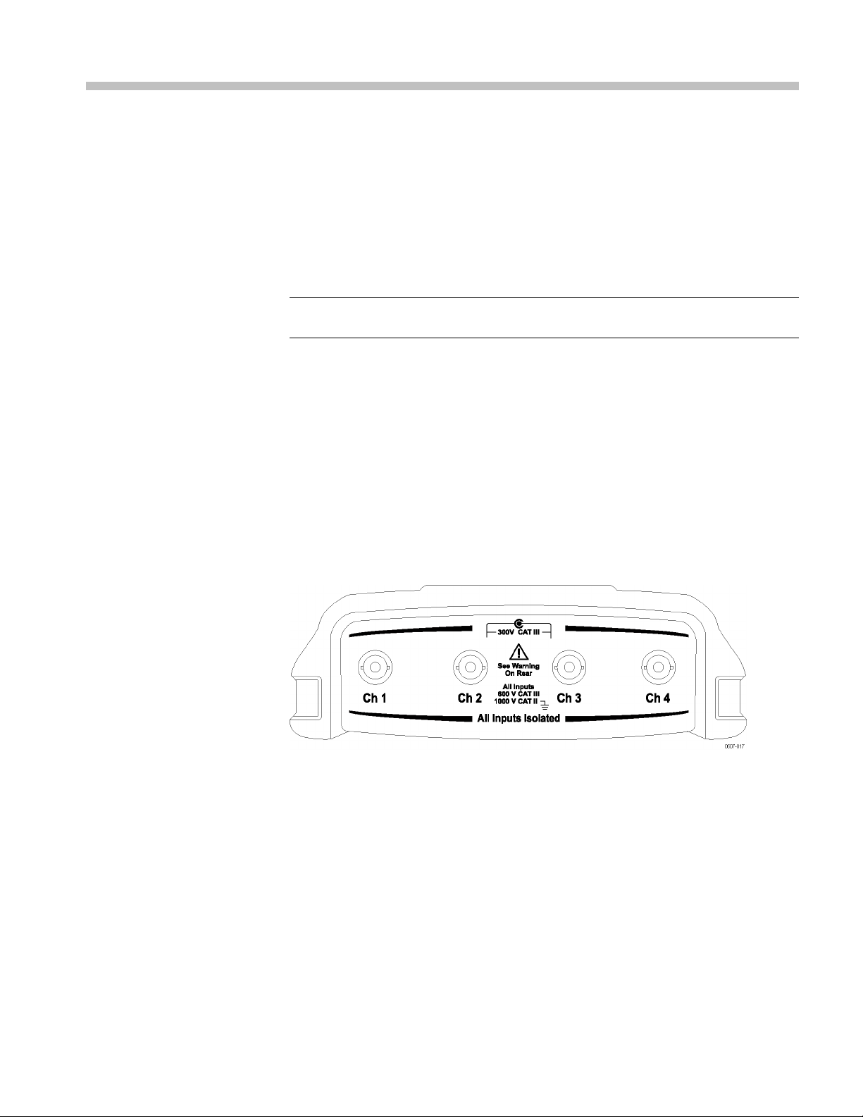
The top panel of the instrument has four safety BNC jack signal inputs. The color
at the base of each BNC input corresponds to the color of the related channel
buttononth
measurements with each input. (See Figure 2-1.)
NOTE. Read the important safety information about taking floating measurements.
(See page 2-2.)
The instrument BNC reference connection is made on the inside of the BNC
connector. The black bayonet on the outside of the BNC connectors does not
provide electrical contact. For a good connection, make sure your probe or cable
connector is pushed on and twist locked. Replace cables or probes that have
worn co
The black bayonet on the outside of the BNC input connectors does not shield
the connector input from unwanted electrical noise from nearby circuits. Connect
a50Ω
establishing a “No Signal” baseline c ondition.
e front panel. Isolated input architecture allows independent floating
nnectors.
terminator or a BNC shorting plug to the input BNC connector when
Figure 2-1: Top panel input connectors
THS3000 Series Oscilloscopes User Manual 2–1

Operating Basics
About Floating Measurements
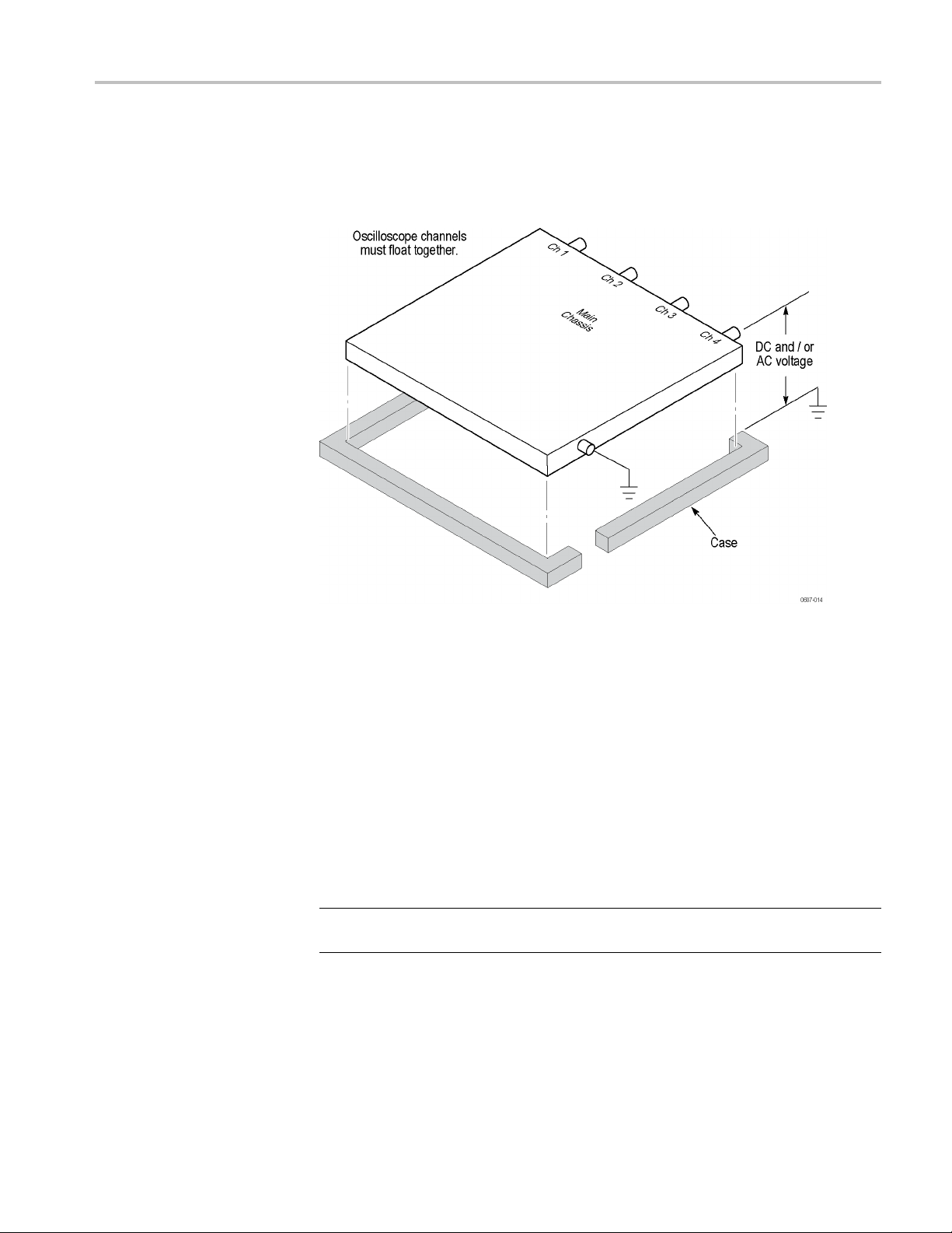
You can use the independently floating isolated inputs to m easure signals that are
independently floating from each other. The instrument has independently floating
isolated inputs. Each input section (1, 2, 3, and 4) has its own signal input and
its own reference input. The reference input of each input section is electrically
isolated fr
The isolated input architecture of this instrument offers the following advantages:
Simultaneous measurement of independently floating signals.
Additional safety. Because the commons are not directly connected, the
chance of causing a short circuit when measuring multiple signals is greatly
reduced.
Additional safety. When measuring in systems with multiple grounds, the
ground currents induced are kept to a minimum.
om the reference inputs of the other input sections. (See Figure 2-2.)
Figure 2-2: Isolated input a rchitecture
2–2 THS3000 Series Oscilloscopes User Manual
Operating Basics
Many handheld o
shares a common reference for the oscilloscope channels. (See Figure 2-3.) With
this architecture, all input signals must have the same voltage reference when you
take any multi-channel measurements.
scilloscope products have the architecture shown below, which
2-3: Common-reference input architecture
Figure
Most b
the insulated case. Without differential preamplifiers or external signal isolators,
bench-top oscilloscopes are not suitable for taking floating measurements.
For oscilloscopes with isolated inputs, references are not connected together
inside the instrument. Therefore, each reference of the used inputs must be
connected to a reference voltage. Independently floating isolated inputs are still
coupled by parasitic capacitance. This can occur between the input references and
the environment, and between the input references mutually. For this reason, you
sho
reference of an input is connected to a high speed and/or high voltage signal, you
should be aware of parasitic capacitance. (See Figure 2-4 on page 2-5.)
NOTE. The input channels are electrically isolated from the USB ports and from
the power adapter input.
ench-top oscilloscopes share the architecture shown above, but without
uld connect the references to a system ground or another stable voltage. If the
THS3000 Series Oscilloscopes User Manual 2–3

Operating Basics
Connect Probe
s and Leads
Beware of High Voltages
You can connect voltage probes and test leads to any or all of the BNC connectors.
When using voltage probes, match the color of the probe with the color at the base
of the BNC con
glance. Following are some examples of how to connect probes and leads.
WARNING. To prevent electrical shock, do not exceed the measurement or floating
voltage ratings for the instrument input BNC connector, probe tip, or probe
reference lead.
Understand the voltage ratings for the probes you are using and do not exceed
those ratings. The following voltage ratings are important to know and understand:
The maximum measurement voltage from the probe tip and BNC signal to the
probe reference lead
The maximum floating voltage from the probe reference lead to earth ground
The maximum measurement voltage from the probe tip and BNC shell to
earth ground
nector to make it easy to see which channel you are using at a
These voltage ratings depend on the probe and your application. Refer to the
Specifications section in this manual for more information. (See page A-12,
Probe Specifications.)
See the instruction sheet that shipped with your probes for more probe safety
information.
RNING. To avoid electric shock, do not use probes that require a ground
WA
connection, such as the Tektronix P5200 High Voltage Differential Probe, with
the THS3000 Series Oscilloscopes. The P5200 High Voltage Differential Probe
requires an instrument with grounded inputs and the TH3000 Series Oscilloscopes
have floating inputs (isolated inputs).
2–4 THS3000 Series Oscilloscopes User Manual

Operating Basics
Attach the Reference
Leads Correctly
If you are using
reference lead for each channel directly to your circuit. These attachments
are required because the channels are electrically isolated; they do not share a
common chassis connection. Use the shortest possible reference lead with each
probe to maintain good signal fidelity.
The probe reference lead presents a higher capacitive load to the circuit-under-test
than the probe tip. When taking a floating measurement between two nodes of a
circuit, attach the probe reference lead to the lowest impedance or least dynamic
of the two n
Parasitic capacitance between probes, instrument, and environment. Parasitic
capacitance can occur between the input references and the environment. For this
reason, you should connect the references to a system ground or another stable
voltage. If the reference of an input is connected to a high speed and/or high
voltage
signal, you should be aware of parasitic capacitance. (See Figure 2-4.)
all four of the instrument channels, you must attach the probe
odes.
ure 2 -4: Parasitic capacitance between probes, instrument, and environment
Fig
THS3000 Series Oscilloscopes User Manual 2–5

Operating Basics
Parasitic capa
can occur between the input references mutually. For example, between an analog
and digital reference. For this reason, you should connect the references to a
system ground or another stable voltage. If the reference of an input is connected
to a high speed and/or high voltage signal, you should be aware of parasitic
capacitance. (See Figure 2-5.)
citance between analog and digital reference. Parasitic capacitance
Figure 2-5: Parasitic capacitance between analog and digital reference
This is the correct way to connect reference leads. (See Figure 2-6.)
Figure 2-6: Correct connection of reference leads
2–6 THS3000 Series Oscilloscopes User Manual

Operating Basics
This is a the wro
reference lead 4 can be transmitted by parasitic capacitance to the analog input
amplifier. (SeeFigure2-7.)
Figure 2-7: Wrong connection of reference leads
ng way to connect reference leads. Noise that is picked up by
THS3000 Series Oscilloscopes User Manual 2–7

Operating Basics
Make Voltage Probe
Connections
To make measure
the channel 1 input, the blue voltage probe to the channel 2 input, the magenta
voltage probe to the channel 3 input, and the green voltage probe to the channel
4 input. Connect the short ground lead of each voltage probe to its own reference
potential. (See Figure 2-8.)
ments on four channels, connect the yellow voltage probe to
Figure 2-8: Making voltage probe connections on four channels.
NOTE.
match the probe to the input channel of the instrument. (See page C-1, Probe
Compensation and Compatible Maximum Voltages.)
For an accurate indication of the measured signal, it is necessary to
2–8 THS3000 Series Oscilloscopes User Manual

Operating Basics
Connections With Probe
Accessories
The following i
attachments.
Connection using a ground spring. The following image shows a voltage probe
connection using a ground spring.
WAR NI NG . To avoid electrical shock or fire, do not connect the ground spring to
voltages higher than 30 Vrms from earth ground.
mages show several different types of probe accessories and their
Figure 2-9: Voltage probe connection using a g round spring
THS3000 Series Oscilloscopes User Manual 2–9

Operating Basics
Connections Us
as shown in the following image, making sure to reapply the insulation sleeve
over the probe tip when the hook tip is not in use to avoid electrical shock. (See
Figure 2-10.)
WARNING. To avoid electrical shock, reapply the insulation sleeve over the
probe tip when the hook clip is not used. This also avoids the risk of accidently
interconne
connected. (See Figure 2-8.)
ing Hook Tips and Alligator Clip Grounding. Connect the probes
cting the reference contact of multiple probes when ground leads are
Figure 2-10: Connections using hook tips and alligator clip grounding
WARNING. To avoid electrical shock use an insulation sleeve if you use the probes
without the probe tip or the ground spring.
2–10 THS3000 Series Oscilloscopes User Manual

Operating Basics
Connections wi
present on the ground ring near the probe tip. The ground ring is shown here.
WAR NI NG . To avoid electrical shock, always use the insulation sleeve or the
probe tip when using the probe reference (ground) lead. The voltage applied to
the reference lead is also present on the ground ring near the probe tip. (See
Figure 2-11.)
Figure 2
-11: Probe tip ground ring
th a ground lead. The voltage applied to the reference lead is also
THS3000 Series Oscilloscopes User Manual 2–11

Operating Basics
Select an Inpu
nPositionandScale
Assig
to Multiple Channels
t Channel
After you have connected probes to the desired inputs, you will want to select
an input channel and set the parameters for that channel. To select a channel,
do the follow
1. Press one of the channel buttons to display the associated input menu and
to turn the i
2. Coupling is DC by default. Select AC coupling if you want to observe a small
AC signal t
will be visible in the lower left portion of the display screen.
NOTE. Autoset can affect how coupling functions. For more information, read
about the Autoset feature. (See page 2-13, Display an Unknown Signal with
Autoset or AutoRange™.)
3. Press the function button to select Input Options and select the desired
attenuation and bandwidth settings. Read m ore about attenuation and
bandwidth settings. (See page 2-22, Acquire Waveforms.)
If the channel button is illuminated, the horizontal and vertical Position and Scale
buttons are assigned to the indicated channel.
ing:
nput on.
hat rides on a DC signal. When AC coupling is active, the 1~ icon
To assign the Position and Scale buttons to multiple channels, do the following:
1. Press and hold the Ch 1 button.
2. Press another one or more channel buttons in sequence.
lease the Ch 1 button.
3. Re
All pressed buttons are now illuminated. The Position and Scale buttons now
pply to all active channels.
a
To deactivate this feature, press a single channel button.
2–12 THS3000 Series Oscilloscopes User Manual

Operating Basics
Adjust the Pro
be Type Settings
To obtain correct measurement results, the instrument probe type settings must
correspond to the connected probe types. To select the Channel 1 probe setting,
do the follow
1. Press the Ch 1 button to display the input menu.
2. Select PROBE 1 from the menu.
3. Select Voltage or Current from the Probe Type submenu.
4. Select the attenuation settings (for voltage probes) or the sensitivity settings
(for current probes) needed for your application.
5. Press the Menu Off button to remove the menu from the display screen.
ing:
Display an Unknown Signal with Autoset or AutoRange™
The Autoset and AutoRange™ features let the instrument d isplay complex,
unknown signals automatically. The Autoset function provides a one time
setup of the vertical, horizontal and trigger systems of the instrument. The
Autoranging function provides continuous auto setup of vertical, horizontal, and
trigger systems that track signal changes. When the signal changes, the setup is
automatically adjusted to maintain the best display result. This feature is useful
for quickly checking several signals.
Enable Autoset
There are several steps to enabling the Autoset feature. The first involves setting
the Autoset parameters as follows:
1. Press the Utility button.
2. Select Options.
3. Check that the Auto Set Adjust menu item is highlighted black, and then
press Enter.
4. Select the frequency range:
If the frequency range is set to 15 Hz and up, the Autoset function responds
more quickly at this range because the instrument is instructed not to analyze
low frequency signal components.
THS3000 Series Oscilloscopes User Manual 2–13

Operating Basics
If the frequenc
analyze low frequency components for automatic triggering.
5. Select Unchan
retains the coupling setting as it is set in the channel button menu of the
active input.
6. Select Unchanged or Set to o n under Display glitches. Selecting the former
retains the glitch setting as it is set in the Acquire > ACQUIRE OPTIONS
menu.
7. Exit the menu.
NOTE. The Autoset option for the signal frequency is similar to the automatic
trigger option for the signal frequency. However, the Autoset option determines
the behavior of the Autoset function and effects show only when you press the
Autoset
The second involves enabling Autoset as follows:
1. Press the Autoset button. AUTOSET will appear in the top right portion of
The waveform identifier (1, 2, 3, or 4) is visible on the right side of the screen.
The zero icon (-) beneath the waveform identifier on the left side of the screen
identifies the ground level of the waveform. (See Figure 2-12.)
button.
the display screen showing you that Autoset is now active.
yrangeissetto1 Hz and up, the instrument is instructed to
ged or Set to DC under Input coupling. Selecting the former
Figure 2-12: Display with Autoset
2–14 THS3000 Series Oscilloscopes User Manual

Operating Basics
Enable AutoRange™
To enable the Au
AUTORANGE appears in the top right corner of the display screen. The
values showing across the bottom of the display screen show range and trigger
information.
The waveform identifier (1, 2, 3, or 4) is visible on the right side of the screen.
The zero icon (-) beneath the waveform identifier on the left side of the screen
identifies the ground level of the waveform. (See Figure 2-13.)
toRange™ feature, press and hold the Autoset button until
Figure 2-13: Display with AutoRange™
Automatic Measurements
This instrument offers a wide range of automatic measurements. In addition to
the waveforms, the instrument can also display measurements: MEASURE A,
B, C, D. These measurements are selectable independently and can be done on
the
channel 1, 2, 3, or 4 input.
THS3000 Series Oscilloscopes User Manual 2–15

Operating Basics
Choose a Frequency
Measurement for Chann el
View a Hz and V Peak-Peak
Measurement
To choose a freq
1. Press the Ch 1 button to turn the input on.
uency measurement for channel 1, do the following:
1
2. Press the Acquire button to view the menu.
3. Select MEASURE.
4. Use the function button under MEASURE A B C D to select the measure
to be displayed. For example, you can select A.
5. Use the arrow keys to select on Ch 1 to assign the measurement to that
channel and select the measurement parameters. Select Hz for frequency.
To choose also a Peak-Peak measurement for channel 2 as a second reading, do
the following after finishing the previous procedure:
1. Press the Ch 2 button to turn the input on.
2. Press the Acquire button and select MEASURE
3. Press the function button to select MEASURE B.
4. Select on Ch2 using the arrow keys and then press the Enter button.
5. Select Peak using the arrow keys and then press the Enter button.
6. Select Peak-Peak.
2–16 THS3000 Series Oscilloscopes User Manual

Operating Basics
The display now
the Hz measurement. The character size will be reduced when more then two
readings are on. (See Figure 2-14.)
Figure 2
-14: Hz and V peak-peak as measurements
shows two measurements and the top left of the screen shows
NOTE. You can set the parameters for all four measurements and assign those to
any of the four channels while the MEASURE menu is open.
THS3000 Series Oscilloscopes User Manual 2–17

Operating Basics
Stop the Displ
ay
You can freeze the display (all measurements and waveforms) at any time by
pressing the Run/Stop button until STOP appears in red in the top right portion
of the displa
yscreenandtheRun/Stop button is illuminated. (See Figure 2-15.)
Figure 2-15: Frozen (stopped) display
Press the Run/Stop button again to unfreeze the display. RUN will appear in
green in the top right portion of the display. (See Figure 2-16.)
. RUN will only appear on the screen if the trigger is set to MANUAL
NOTE
from the Trigger button menu.
2–18 THS3000 Series Oscilloscopes User Manual

Figure 2-16: Live (running) display
Operating Basics
Average, Persistence, and Glitch Capture
Use the average functions to smooth waveforms by suppressing random or
elated noise in the waveform without loss of bandwidth. Waveform samples
uncorr
with and without smoothing are shown here. (See Table 2-1.)
Smooth a Waveform With
ging
Avera
To smooth a waveform using averaging, do the following:
1. Press the Acquire button.
2. Select ACQUIRE OPTIONS.
3. Press the right arrow key to navigate to Average and black-highlight On...
4. Press the Enter button.
5. Sel
ect average factor Average 64. This averages the outcomes of 64
acquisitions.
THS3000 Series Oscilloscopes User Manual 2–19

Operating Basics
6. Select Normal o
Normal averaging. In the normal average mod
waveform distort the averaged wave shape, and do not show up on screen clearly.
When a signal really changes, for instance when you are probing, it takes some
time before the new wave shape is stable.
Smart averaging. Smart averaging allows you to quickly probe. Incidental
waveform changes, like a line flyback in video, show up on screen instantly.
Table 2-1: Comparison of averaged versus nonaveraged waveforms
Waveform with Averaging Waveform with no averaging
r Smart average.
e, occasional deviations in a
Use Persistence, Envelope,
and Dot-Join to Display
Waveforms
You can use persistence to observe dynamic signals. (See Figure 2-17.)
1. Open the ACQUIRE OPTIONS menu.
2. From the Waveform submenu, black-highlight Persistence... and press the
Enter button.
3. From the Digital Persistence and Display submenus, you can select the
following:
Select Short, Medium, Long,orInfinite to observe dynamic waveforms
like on an analog oscilloscope.
Select Off and Display Envelope to see the upper and lower boundaries of
dynamic waveforms (envelope mode).
Select Display Dot-join OFF to display measured samples only. Dot
join off may be useful when measuring for example modulated signals
or video signals.
Select Display Normal to turn the envelope mode off and the dot-join
function on.
2–20 THS3000 Series Oscilloscopes User Manual

Figure 2-17: Using persistence to observe dynamic signals
Operating Basics
Glitche
To capture glitches on a waveform, do the following:
s
1. Open the ACQUIRE OPTIONS menu.
2. Select Glitch On.
3. Press
You can use this function to display events (glitches or other asynchronous
wavef
you can display HF modulated waveforms.
When
off. In the 2 mV/div range, you can manually set glitch detect on.
CLOSE to exit the menu.
orms) of 8 ns (due to ADC’s with 125 MS/s sampling speed) or wider, or
you select the 2 mV/div range, glitch detect will automatically be turned
THS3000 Series Oscilloscopes User Manual 2–21

Operating Basics
Suppress High Frequ ency
Noise
Acquire Waveforms
Turning glitch
Averaging will suppress the noise even more:
1. Open the ACQUI
2. Select Glitch Off.
3. Select Average On to open the Average menu
4. Select Av era ge 8.
You can read more about averaging and how to use it. (See page 2-19, Smooth
a Waveform With Averaging.)
NOTE. Glitch capture and average do not affect bandwidth. Further noise
suppression is possible with bandwidth limiting filters. (See page 2-24, Adjust
Bandwidth to Smooth Waveforms.)
Before the instrument can display a signal, the signal must pass through the input
channel where it is scaled and digitized. Each channel has a dedicated input
amplifier and digitizer. Each channel produces a stream of digital data from
which the instrument extracts waveform records. You can set a variety of signal
acquisition parameters as described in this section.
detect off will suppress the high frequency noise on a waveform.
RE OPTIONS menu.
cquisition Speed and
Set A
Waveform Memory Depth
To set the acquisition speed, do the following:
1. Press the Acquire button.
2. Select ACQUIRE OPTIONS.
ttheMemory to one of the following:
3. Se
Short: For faster trace update rate; shortest record length, decreased zoom
ate.
r
Long: Maximum waveform detail; 10,000 samples per trace record length,
aximum zoom rate, lower trace update rate.
m
2–22 THS3000 Series Oscilloscopes User Manual

Operating Basics
Reverse the Attenuation of
the Displayed Waveform
Variable Input Sensitivity
You may want to r
a negative-going waveform is displayed as a positive-going waveform which
may provide a more meaningful view. An inverted display is identified by an
inversed trace identifier (
below the waveform. To invert a waveform, do the following for whichever input
channel you are using:
1. Press the desired channel button.
2. Select the INPUT OPTIONS submenu.
3. Select Inverted for the Attenuator setting.
4. Exit the menu.
The varia
continuously. For example, to set the amplitude of a reference signal to exactly
6 divisions.
The input sensitivity of a range can be increased up to 2.5 times, for example
between 10 mV/div and 4 mV/div in the 10 mV/div range.
NOTE. Variable input sensitivity is not available in the Mathematics functions
(+, –, x, and FFT).
ble input sensitivity allows you to adjust any input sensitivity
everse the attenuation of a displayed waveform. For example,
) at the right of the waveform, and in the status line
To use the variable input sensitivity, do the following for whichever input channel
you are using:
1. Press the Autoset button. The word AUTOSET will appear in the top right
portion of the display screen until the autoset is complete.
NOTE. The autoset will turn off the variable input sensitivity. You can now select
the required input range. Keep in mind that the sensitivity will increase when
u start adjusting the variable s ensitivity (the displayed trace amplitude will
yo
increase).
2. Press the channel button for the desired input to open the input menu.
3. Select INPUT OPTIONS.
4. Select Va riab l e attenuation.
THS3000 Series Oscilloscopes User Manual 2–23

Operating Basics
5. Exit the menu. You will see the channel number and Va r in the left bottom
portion of the display screen.
NOTE. Selecting Variable will turn off cursors and automatic input ranging. Press
the Vertic
al Position buttons to increase or decrease sensitivity.
Adjust Bandwidth to
Smooth Wa
veforms
You can use bandwidth filters to suppress high frequency noise on waveforms by
g the working bandwidth to 20 kHz or 20 MHz. The application of filters
limitin
will smooth the displayed waveform. For the same reason, it will also improve
triggering on the waveform.
To us e th e HF reject filter on a desired input channel, do the following:
1. Press
2. Select INPUT OPTIONS.
3. Select the 20 kHz (HF reject) bandwidth.
NOTE. To suppress noise without loss of bandwidth, use the average function or
turn off Display Glitches. (See page 2-19, Smooth a Waveform With Averaging.)
the channel button for the active input to view the menu.
Using Mathematics
Functions +, –, x, XY-mode
2–24 THS3000 Series Oscilloscopes User Manual
You can add (+), subtract ( -), or multiply (x) two waveforms. The instrument will
display the mathematical result wa veform and the source waveforms.
The XY-mode provides a plot with one input on the vertical axis and the second
input on the horizontal a xis.
The Mathematics functions perform a point-to-point operation on the involved
waveforms.

Operating Basics
To use a Mathe ma
1. Press the Acquire button.
2. Select ACQUIRE OPTIONS.
3. Select Mathematics from the Waveform options.
4. Select a function and then a channel for an A and B source.
tics function, do the following:
5. Once you have selected the function and sources, a new menu will appear and
you should select from the options that menu provides. The menu varies
by function as follows:
+, - :
x:
XY-Mode:
FFT:
NOTE. The sensitivity range of the mathematical result is equal to the sensitivity
range of the least sensitive input divided by the scale factor.
THS3000 Series Oscilloscopes User Manual 2–25

Operating Basics
Using Mathematics
Function Spectrum (FFT)
The spectrum fu
waveform(s) in the input trace color. It performs an FFT (Fast Fourier Transform)
to transform the amplitude waveform from the time domain into the frequency
domain.
To reduce the effect of side-lobes (leakage) it is recommended to use Auto
windowing. This will automatically adapt the part of the waveform that is
analyzed to a complete number of cycles.
Selecting Hanning, Hamming, or no windowing results in a faster update, but
also in more leakage.
Check that the entire waveform amplitude remains on the screen.
To use the FFT function, do the following:
1. Press the Acquire button.
2. Select A
3. Select Mathematics from the Waveform options.
nction shows the spectral content of the input 1, 2, 3, or 4
CQUIRE OPTIONS.
2–26 THS3000 Series Oscilloscopes User Manual

Operating Basics
4. Select functio
5. Check that FFT shows at the top right of the display screen that appears.
(See Figure 2-18.)
If LOW AMPL shows, a spectrum measurement cannot be done because
the waveform amplitude is too low.
If WRONG TB shows, the time base setting does not enable the instrument to
display an FFT result. It is either too slow, which can result in aliasing, or t oo
fast, which results in less than one signal p eriod on the screen.
n FFT and then Source channel and a Window type.
Figure 2-18: FFT measurement
6. Once you have selected the Function, Source, and Window settings, a new
menu will appear at the bottom of the display screen.
elect the input on which you want to perform the FFT by pressing the
7.S
function button under the INPUT menu item.
THS3000 Series Oscilloscopes User Manual 2–27

Operating Basics
Compare Waveforms
8. Set the vertica
pressing the function button under that menu item.
9. You can turn th
or OFF under the FFT menu item.
Youcandisplayafixed reference waveform with the actual waveform for
comparison.
To create a reference waveform and to display it with the actual waveform, do
the following:
1. Press the Acquire button.
2. Select ACQUIRE OPTIONS.
l amplitude scale to logarithmic (LOG)orlinear(LINEAR)by
e FFT display on and off (toggle function) by selecting ON
2–28 THS3000 Series Oscilloscopes User Manual

Operating Basics
3. Select Referen
4. Select On under Reference to display the reference waveform. The reference
waveform can be:
the last used reference waveform (if not available, no reference waveform
will be shown)
the envelope waveform (if the persistence function Envelope is on)
ce from the Waveform options.
5. Or, select Recall… to recall a saved waveform (or waveform envelope) from
memory and use it as a reference waveform.
6. Or, select New… to open the NEW REFERENCE menu and select the width
of an additional envelope to be added to the momentary waveform.
7. Press Enter to store the momentary waveform and display it permanently for
reference. The display screen also shows the actual waveform.
NOTE. To recall a saved waveform from memory and use it as a reference
waveform, read about recalling screens with associated setups. (See page 3-28.)
Reading a reference waveform with an envelope. Following is an example of a
reference waveform with an additional envelope of ±2 pixels. 1 vertical pixel
THS3000 Series Oscilloscopes User Manual 2–29

Operating Basics
Pass-Fail Testing
on the display i
s 0.04 × range/div. 1 horizontal pixel on the display is 0.0333
× range/div.
Table 2-2:
Pixel colo
black pixels
gray pixels ± 2 pixels envelope
You can u
Pixel colors description
r
Descripti
basic wav
on
eform
se a reference waveform as a test template for the actual waveform. If at
least one sample of a waveform is outside the test template, the failed or passed
scope screen will be stored. Up to 100 screens can be stored. If the memory is
full, the first screen will be deleted in favor of the new screen to be stored.
The most appropriate reference waveform for the Pass Fail test is a waveform
envelope.
To use the Pass-Fail function using a waveform envelope, do the following:
1. Display a reference waveform as described in the previous section Comparing
Waveforms. (See page 2-28.)
2. From the Acquire button ACQUIRE OPTIONS menu, select Reference.
lect one of the following options from the Pass Fail Testing menu:
3. Se
Store “Fail”: Each screen with samples outside the reference will be
ored.
st
Store “Pass”: Each screen with no samples outside the reference will
estored.
b
Off: No screens will be stored.
Each time a screen is stored you will hear a beep. You can read more about how
to analyze stored screens using replay, zoom, and cursors. (See page 3-6, Analyze
Wavef orms .)
2–30 THS3000 Series Oscilloscopes User Manual

Functional Overview


Recorder Functions
This chapter provides a step-by-step introduction to the recorder functions of
the instrument. The introduction gives examples to show how to use the menus
and perform basic operations.
Access the RECORDER REPLAY.. menu by first pressing the Acquire button.
From the RECORDER REPLAY.. menu, you can now choose from the recorder
functions.
Figure 3-1: RECORDER REPLAY main menu
Plot Measurements Over Time (TrendPlot™)
Use the TrendPlot™ function to plot a graph of measurements as a function of
time. When simultaneously plotting two readings, the screen area is split into
two sections of four divisions each. When simultaneously plotting three or four
readings, the screen area is split into th ree or four sections of two divisions each.
To start a trend plot, do the following:
1. Make an automatic measurement. The following steps will then plot that
information. (See page 2-15, Automatic Measurements.)
2. Select RECORDER REPLAY.. from the Acquire button menu.
3. Select TREND PLOT.
NOTE. If autoranging is not on, you will be asked if you would like to turn it on
before plotting. Select YES if you expect wide changes to the input signal.
5. Observe that the word RECORDING is showing in the right top portion of
the display screen. From t he menu that appears, you can select a reference
(Time of Day or From Start) from the OPTIONS.. menu. You can also
select to view all data in memory (VIEW ALL) or just the twelve most
recently recorded divisions (NORMAL).
6. Select STOP under the RECORDER menu item to stop plotting.
7. Observe that the recorded time from start appears at the bottom of the display
screen. The present reading appears on the top of the display screen. The
THS3000 Series Oscilloscopes User Manual 3–1

Recorder Functions
following disp
(See Figure 3-2.)
NOTE. Read more about analyzing waveform using cursors. (See page 3-9.)
8. To turn off the TrendPlot™ display, select EXIT RECORDER.
lay shows a trend plot with cursors enabled for measurement.
Figure 3-2: TrendPlot™ measurement
The instrument continuously records the digital readings of the measurements and
ays these as a graph. The TrendPlot™ graph moves from right to left like
displ
a paper chart recorder.
the instrument is in automatic mode, automatic vertical scaling is used
When
to fitthegraphonthescreen.
NOTE. Whentherecordermemoryisfull,anautomatic compression algorithm is
used to compress all samples into half of the memory without loss of transients.
The other half of the recorder memory is free again to continue recording.
3–2 THS3000 Series Oscilloscopes User Manual

Recorder Functions
Record Wavefo
Start Scope Roll Mode
rmsInDeepMemory(ScopeRollMode)
The SCOPE ROLL MODE function logs a long waveform of each active input.
Use this function to monitor waveforms such as motion control signals or the
power-on eve
fast transients are captured. Because of the deep memory, recording can be done
for more than one day. This function is similar to the roll mode in many d igital
sampling oscilloscopes, but has deeper memory and better functionality.
To record the channel 1 and channel 2 waveform, do the following:
1. Apply sig
2. Select RECORDER REPLAY.. from the Acquire button menu.
3. Select SCOPE ROLL MODE.
4. The waveform moves across the screen from right to left like on a normal
chart recorder. Observe that the screen displays the time from start at the top
and the status at the bottom of the screen, which includes the time/div setting
and th
5. Press the function button under the RECORDER menu item and select
STOP t
nt of an Uninterruptable Power Supply (UPS). During recording,
nals to the channel 1 and channel 2 inputs.
e total timespan that fits the memory. (See Figure 3-3.)
ostoprecordingwhenyouareready.
Figure 3-3: Recording waveforms using Scope Roll Mode
THS3000 Series Oscilloscopes User Manual 3–3

Recorder Functions
Use Single Sweep Mode
UseTriggeringtoStartor
Stop Scope Roll Mode
You can use the r
when the deep memory is full. To activate single sweep mode, do the following:
1. Set up the instrument as in the previous procedure. (See page 3-3, Start Scope
Roll Mode.)
2. Select OPTIONS from the SCOPEROLLMODEmenu.
3. Use the right arrow to highlight Single Sweep mode and press the Enter
button.
4. Press the function button under the RECORDER menu item and select RUN
to begin recording in single sweep mode.
To record an electrical event that causes a fault, it might be useful to start or stop
recording on a trigger signal:
ecorder Single Sweep mode to automatically stop recording
Start on trigger to start recording; recording stops when the deep memory is full.
Stop on trigger to stop recording.
Stop when untriggered to continue recording if a next trigger comes within
1 division in vi
To set up the instrument to start or stop recording on a trigger signal, do the
following:
1. Set up the instrument as in the Start Scope Roll Mode procedure. (See
page 3-3.)
2. Select OPTIONS from the SCOPEROLLMODEmenu.
3. Use the right arrow to highlight on Trigger mode and press the Enter button.
4. Select on of the conditions from the STARTSINGLESWEEPON
TRIGGERING menu.
ew all mode.
3–4 THS3000 Series Oscilloscopes User Manual

Recorder Functions
Samples are con
twelve recorded divisions are displayed on the screen. Use View All to display
the full memory contents.
NOTE. You can learn more about Single Shot triggering. (See page 3-20.)
tinuously saved in deep memory during recording. The last
THS3000 Series Oscilloscopes User Manual 3–5

Analyze Waveforms
Analyze Wavef
Use Replay
orms
You can u s e t h
waveform analyses. These functions can be used with one or more of the primary
functions: Acquire, TrendPlot™, or Data Log Replay.
It is possible to combine two or three analysis functions. A typical application
using these functions is:
First replay the last screens to find the screen of special interest.
Then zoom i
Finally, make measurements using the cursors.
When you are in acquire mode, the instrument automatically stores the 100 most
screens. Records are captured and frozen when you press the Run/Stop
recent
button. You can also use the Replay function to store and view signals even if
you did not press Run/Stop.
Use the options in the DATA LOG REPLAY menu to review stored screens.
e Replay, Zoom, and Cursors analysis functions to perform detailed
n on the signal event.
Replay an Acquired Screen
To review a specific stored screen, do the following:
1. Press the Acquire button.
2. Select the RECORDER REPLAY.. menu option.
3. Select DATA LOG REPLAY.
4. Select Next or Previous to scroll through the stored screens until you find
the one you want.
5. Observe that the top portion of the DATA LOG REPLAY menu (shown in
step 4) displays a replay bar with a screen number and related time stamp.
The replay bar represents all 100 stored screens in memory. The
represents the picture being displayed on the screen. If the bar is partly white,
the memory is not completely filled with 100 screens.
icon
3–6 THS3000 Series Oscilloscopes User Manual

Analyze Waveforms
Replay All Acquired
Screens
Turn Off the Replay
Function
You can also rep
To replay all acquired screens, do the following:
1. Press the Acquire button.
2. Select the RECORDER REPLAY.. menu option.
3. Select DATA LOG REPLAY to view the replay menu.
4. Select Play to start play of all stored screens, from oldest to newest.
NOTE. Once you have selected to play all screens, the instrument will continue
to repeat play until you select Stop or Exit Replay.
5. Select Stop when you come to the screen of interest. You can now use the
zoom and cursor functions to study the signal in more detail.
Select EXIT REPLAY to turn off the replay function. A warning notice will
appear stating that all replay data will be lost. This means you will not be able
to return to access the data again without saving it first by pressing the Save
button. Select YES.
lay all of the stored screens in sequence, from oldest to newest.
Capturing 100 Trigger
Events Automatically
Use Zoom
When you use the instrument in triggered mode, 100 trigger event screens are
captured. By combining the trigger possibilities with the capability of capturing
100 screens for later replay, you can leave the instrument unattended to capture
intermittent signal anomalies. This way you could use Pulse Triggering to trigger
and capture 100 intermittent glitches or you could capture 100 UPS startups.
NOTE. You can read more about triggering and trigger setup. (See page 3-14,
Trigger Functions.)
Use the Zoom function to obtain a more detailed view of a waveform. To zoom
in on a waveform, do the following:
1. Press the Zoom
2. Press the up and down arrow keys (or horizontal Scale key) to enlarge
(decrease the time/div) and shrink (increase the time/div) the waveform,
respectively. Press the right and left arrow keys (or the horizontal Position
button.
THS3000 Series Oscilloscopes User Manual 3–7

Analyze Waveforms
key) to move the
shows the position of the zoomed part in relation to the total waveform.
Observe that the bottom of the waveform area displays the zoom ratio, position
bar, and time/div. The zoom range depends on the amount of data samples stored
in memory. (See Figure 3-4.)
waveform to the right or left of the screen. The position bar
Figure 3-4: Zooming in on a Waveform
NOTE. To turn off the Zoom function, select OFF under the ZOOM item of the
menu.
3–8 THS3000 Series Oscilloscopes User Manual

Use Cursors
Analyze Waveforms
Cursors allow you to make precise digital measurements on waveforms. This can
be done on live waveforms, recorded waveforms, and on saved waveforms.
Use Horizont
al Cursors on
a Waveform
To use the cursors for a voltage measurement, do the following:
1. Press the Cursors button
2. Select the = cursors. The cursor type options are:
׀ :Singlev
׀׀ : Two vertical cursors
= : Two horizontal cursors
: Rise time cursor
: Fall time cursor
3. Press the function key under the MOVE menu item to highlight the upper
cursor (if it is not already highlighted).
4. Use t
5. Press the function key under the MOVE menu item to highlight the lower
6. Use the up and down arrow keys to position the lower cursor.
he up and down arrow keys to position the upper cursor.
or.
curs
ertical cursor
TE. Even when the key labels are not displayed at the bottom of the screen,
NO
you still can use the arrow keys. This allows full control of both cursors while
having a full screen view.
7. Use the cursors to measure the amplitude, high or low value, or overshoot
of the waveform.
This screen shows the voltage difference between the two cursors and the voltage
at the cursors. (See Figure 3-5.)
THS3000 Series Oscilloscopes User Manual 3–9

Analyze Waveforms
Figure 3-5: Voltage measurement with horizontal cursors
Use Vert
ical Cursors on a
Waveform
To use the cursors for a time measurement (T, 1/T), for a mVs-mAs-mWs
measurement, or for an RMS measurement of the trace section between the
cursors, do the following:
1. Press the Cursors button
2. Select the ׀׀ cursors. The cursor type options are:
׀ : Single vertical cursor
׀׀ : Two vertical cursors
= :Tw
o horizontal cursors
: Rise time cursor
: Fall time cursor
3–10 THS3000 Series Oscilloscopes User Manual

Analyze Waveforms
3. Select T (time)
T: time
1/T: 1/time or frequency
mVs: Millivolts per second
NOTE. This option varies depending on the probe type you have selected in
the channel button Probe menu. Other options include mAs (milliamperes
per second
are using the Mathematical function x and the probe type for one channel is
voltage and another channel is current. If you are taking cursor measurements
while using mathematical functions +, -,orx, no measurement will be
available if the input 1 and 2 measurement units are different. If you are using
the mathematical function FFT, you must activate cursors from the Cursor
button m
can read more about using the Mathematical functions. (See page 2-24.)
4. Press the function key under the MOVE menu item to highlight the left cursor
(if it
enu. You can then turn cursors on and off from the FFT menu. You
RMS:Ro
is not already highlighted).
for the measurement type. The measurement type options are:
) for current probes, and mWs (milliwatts per second) when you
ot mean squared
5. Use t
6. Press the function key under the MOVE menu item to highlight the right
7. Use the left and right arrow keys to position the right cursor.
NO
you still can use the arrow keys. This allows full control of both cursors while
having a full screen view.
8. Use the cursors to measure the time and voltage differences.
This screen shows the time difference between the two cursors and the voltage
difference between the two markers. (See Figure 3-6.)
he left and right arrow keys to position the left cursor.
sor.
cur
TE. Even when the key labels are not displayed at the bottom of the screen,
THS3000 Series Oscilloscopes User Manual 3–11

Analyze Waveforms
Figure 3-6: Time measurement with vertical cursors
UseRisetimeorFalltime
Cursors on a Waveform
The steps to measure either rise time or fall time are similar. To measure rise
time using cursors, do the following:
1. Press the Cursors button
2. Select the
׀ : Single vertical cursor
׀׀ : Two vertical cursors
= : Two horizontal cursors
: Rise time cursor
: Fall time cursor
3. If MANUAL is not already highlighted, press the function key under the
AUTO/MANUAL menu item to highlight MANUAL.
NOTE. Select AUTO to automatically complete steps 4 through 7.
4. Press the function key under the MOVE menu item to highlight the upper
cursor (if it is not already highlighted).
cursor. The cursor type options are:
5. Use the up and down a rrow keys to position the upper cursor to 100% of the
trace height. A marker is shown at 90%.
3–12 THS3000 Series Oscilloscopes User Manual

Analyze Waveforms
6. Press the funct
cursor.
7. Use the up and d
trace height. A marker is shown at 10%.
NOTE. Even when the key labels are not displayed at the bottom of the screen,
you still can use the arrow keys. This allows full control of both cursors while
having a full screen view.
8. Use the cursors to measure the amplitude, high or low value, or overshoot
of the waveform.
This screen shows the risetime measurement from 10%-90% of the trace
amplitude. (See Figure 3-7.)
ion key under the MOVE menu item to highlight the lower
own arrow keys to position the lower cursor to 0% of the
ure 3-7: Risetime measurement using cursors
Fig
THS3000 Series Oscilloscopes User Manual 3–13

Trigger Functions
Trigger Functions
About this Chapter
Trigger Event
Trigger Modes
This chapter provides an introduction to the trigger functions of the instrument.
Triggering tells the instrument when to begin displaying the waveform. You can
use fully automatic triggering, take control of one or more main trigger functions,
or you can use dedicated trigger functions to capture special waveforms.
The trigger event establishes the time-reference point in the waveform record. All
waveform record data is located in time with respect to that point. The instrument
continuously acquires and retains enough sample points to fill the pretrigger
portion of the waveform record. That is the part of the waveform that is displayed
before, or to the left of, the triggering event on screen. When a trigger event
occurs, the instrument is acquiring samples to build the posttrigger portion of the
waveform record, that is, the part displayed after or to the right of the trigger
event. After a trigger is recognized, the instrument will not accept another trigger
until the acquisition is complete.
The trigger mode determines how the instrument behaves in the absence of a
trigger event. You can use the following settings for updating the trigger condition
by pressing the Tri gge r button and then selecting TRIGGER OPTIONS and
then TRIGGER CONDITIONS.
Automatic Auto Level trigger mode enables the instrument to set the trigger
level automatically and track with changes in signal amplitude.
Normal trigger mode enables the instrument to acquire a waveform only
when it is triggered. If no trigger occurs, the last waveform record acquired
remains on the display. If no last waveform exists, no waveform is displayed.
Auto trigger m ode enables the instrument to acquire a waveform even if a
trigger does not occur. Auto mode u
is started, and the pretrigger information is obtained. If a trigger event is not
detected before the timer times out, the instrument forces a trigger. The length
of time it waits for a trigger event depends on the time base setting.
Auto mode, when forcing triggers in the absence of valid triggering events,
does not synchronize the waveform on the display. T he waveform will appear
to move across the screen. If valid triggers occur, the display will become
stable.
Single Shot trigger mode allows you to set the instrument to capture (an
stop) only one trigger event by pressing the front panel Single button. You
can also stop single shot triggering by selecting a different trigger mode in the
Trigger > TRIGGER OPTIONS > Trigger Conditions menu.
Read the Getting Started section for a complete description of the Trigger button
menu. (See page 1-2, Front Panel Navigation.)
ses a timer that starts when the acquisition
d
3–14 THS3000 Series Oscilloscopes User Manual

Trigger Functions
Trigger Filter
Trigger filteri
ng determines what part of the signal is passed to the trigger circuit.
Edge triggering can use both available filter type s: Noise Reject and HF Reject.
Following are
some typical trigger applications:
Use the AutoRange™ function to have full automatic triggering and stable
display of m
ost waveforms.
If the signal is unstable or has a very low frequency, you can control the
trigger lev
el, slope, and trigger delay for a better view of the signal. (See
next section.)
For dedica
ted applications, use one of the three manual trigger functions:
Edge triggering
Video triggering
Pulse Width triggering
Choose a Trigger Type
You can select from the following trigger types:
Table 3-1: Trigger types
Trigger type Trigger conditions
Edge
Pulse width Trigger on pulses that are less than, greater than,
Trigger on a rising, falling, or either rising or falling
edges, as defined by the slope control. Filter
choices are HF Reject and Noise Reject.
Edge triggers are the simplest and most commonly
used trigger type, with both analog and digital
signals. An edge trigger event occurs when the
trigger source passes through a specified voltage
level in the specified direction.
equal to, or not equal to a specified time. You can
trigger on positive or negative pulses. Pulse width
triggers are primarily used on digital signals.
THS3000 Series Oscilloscopes User Manual 3–15

Trigger Functions
Table 3-1: Trigger types (cont.)
Trigger type Trigger conditions
Video
Rise/Fall time Trigger on rise and fall times. Trigger on pulse
Trigger on specified fields or lines of a composite
video signal. Only composite signal formats are
supported.
Trigger on NTSC, PAL, PALPIus, SECAM, or non
interlaced signals.
edges that traverse between two thresholds at
faster or slower rates than the specified time.
pulse edges as positive (
Specify
) or either ( ).
(
) or negative
Set Trigger L evel and Slope
The AutoRange™ function enables hands-off triggering to display complex
unknow
n signals. To manually optimize trigger level and slope, do the following:
1. Press the Autoset button to perform an auto set. When the process is
ete, RUN will appear at the top right of the display screen. This will
compl
ensure a stable display of most any signal.
2. Pres
stheTrigger button.
3. Select to trigger on either the positive slope or negative slope of the chosen
eform. If you select dual slope triggering (
wav
) the instrument triggers on
both the positive slope and negative slope.
4. If MANUAL is not already highlighted, press the function key under that
menu item to highlight it.
5. Adjust the trigger level using the Trigger Level buttons.
3–16 THS3000 Series Oscilloscopes User Manual

Figure 3-8: Screen with all trigger information
Trigger Functions
rigger Delay or
Set T
Pretrigger
In the following screen, observe the trigger icon
position, trigger level, and slope.
At the bottom of the screen the trigger parameters are displayed. For example,
means that channel 1 is used as the trigger source with a positive slope.
When a valid trigger signal is found, the trigger button will be lit and the trigger
parameters appear in white.
When no trigger is found, the trigger parameters appear in gray, and the button
backlight will be off.
You can begin to display the waveform some time before or after the trigger
point is detected using pretrigger (negative delay) or trigger delay, respectively.
Initially, you will see a h alf screen (6 divisions) of negative delay.
Set trigger delay. Hold down the horizontal Position left button until the trigger
icon moves to the new trigger position and changes to include arrows, like this:
. This icon indicates that you have selected a trigger delay. Moving the trigger
icon to the right on the display gives you a pretrigger view. This allows you to see
what happened before the trigger event, or what caused the trigger.
In case of a trigger delay, the status at the bottom of the display screen will change
to include an arrow denoting the delay. For example:
that indicates the trigger
This means that channel 1 is used as the trigger source with a positive slope. The
9.20 ms indicates the (positive) delay between trigger point and waveform display.
THS3000 Series Oscilloscopes User Manual 3–17

Trigger Functions
Set Automatic Trigger
When a valid tri
parameters appear in white.
When no trigge
backlight will be off.
The followi
example of a pretrigger view of 8 divisions (bottom). (See Figure 3-9.)
Figure 3-9: Trigger delay or pretrigger view
In the trigger menu, you can change settings for automatic triggering as follows:
1. Press t
gger signal is found, the trigger button will be lit and the trigger
r is found, the trigger parameters appear in gray, and the button
ng image shows an example of a trigger delay of 500 ms (top) and an
he Trigger button.
2. Select TRIGGER OPTIONS from the menu.
3. Select Automatic Auto Level.
4. Select the trigger threshold: > 15 Hz or > 1 Hz. If the frequency range of the
automatic triggering is set to >15 Hz, the Autoset function responds more
quickly because the instrument is instructed not to analyze low frequency
signal components. However, when you measure frequencies lower than
Hz, you need to select > 1 Hz to analyze low frequency components for
15
automatic triggering.
3–18 THS3000 Series Oscilloscopes User Manual
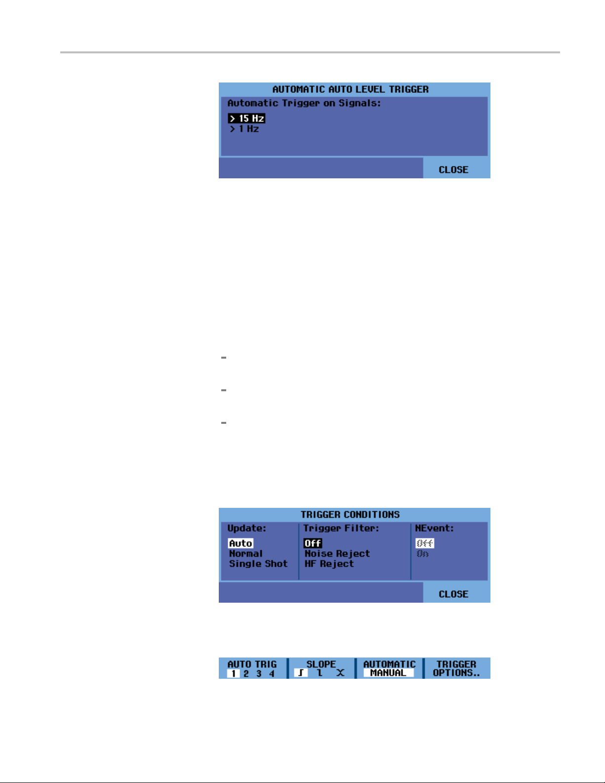
5. Exit the menu.
Trigger Functions
Trigger on Edges
If the signal is unstable, complex, or has a very low frequency, use edge triggering
to obtain ful
waveform, do the following:
1. Press the Trigger button.
2. Select TRIGGER OPTIONS.
3. Select Trigger Conditions.
4. Select one of the following. In most cases, it is advised to use the Auto mode:
5. Select Off for the Trigger Filter and press the Enter button.
l manual trigger control. To trigger on the rising edge of the Ch 1
Auto: the instrument will update the screen even if there are no triggers.
A trace always appears on the scree n.
Normal: the instrument needs a trigger to display a waveform. Use this
mode to update the screen only when valid triggers occur.
Single Shot: the instrument waits for a trigger. After receiving a trigger,
the waveform is displayed and the instrument stops acquisition until the
Single button or Run/Stop button is pressed. The single shot trigger is
enabledbypressingtheSingle button or from the Tr igg er > TRIGGER
OPTIONS > Trigger Conditions menu.
6. The menu that now appears at the bottom of the display screen allows you to
select specific edge trigger settings: trigger channel, slope, and level. Adjust
these settings as desired.
THS3000 Series Oscilloscopes User Manual 3–19

Trigger Functions
Trigger on nois
noisy waveforms, you can use a trigger filter, as follows:
1. Press the Trig
2. Select TRIGGER OPTIONS.
3. Select Trigger Conditions.
4. Select a trigger filter:
Noise Reject: an increased trigger gap will be applied
HF Reject: HF noise on the (internal) trigger signal will be suppressed
NOTE. You can also smooth noisy waveforms without changing bandwidth. (See
page 2-19, Smooth a Waveform With Averaging.)
Single shot trigger. To make a single shot measurement, do the following:
1. Press the Trigger button.
2. Select
3. Select Trigger Conditions.
y waveforms. To reduce jitter on the screen when triggering on
ger button.
TRIGGER OPTIONS.
4. Sel
5. Press the Single button to set the instrument to trigger again. The word RUN
3–20 THS3000 Series Oscilloscopes User Manual
ect Single Shot.ThewordSINGLE will appear in the top right portion of
the display screen indicating that the instrument is waiting for a trigger. As
soon as it receives a trigger, the waveform is displayed and the instrument is
set to stop. This is indicated by the word STOP in the top right portion of
the screen. (See Figure 3-10.)
will appear in the top right portion of the screen when the instrument is set
trigger again.

Figure 3-10: Making a single shot measurement
Trigger Functions
NOTE. Th
Replay function to look at all the stored single shots. (See page 3-6, Use Replay.)
N-Even
n-event burst waveforms. Each next trigger is generated after the waveform has
crossed the trigger level N times in the direction that complies with the selected
trigger slope.
To select N-Event triggering, do the following:
1. Press the Trigger button.
2. Sel
3. Select Trigger Conditions.
e instrument stores all single shots in the replay memory. Use the
t trigger. N-Event triggering enables you to create a stable picture of
ect TRIGGER OPTIONS.
elect Normal or Auto for update, check that the trigger filter is set to Off,
4.S
and then select On for the NEvent.
THS3000 Series Oscilloscopes User Manual 3–21

Trigger Functions
5. Press the funct
right and left arrow keys to select the number of events.
6. Press the Tr igg er Le vel buttons to adjust the trigger level.
This screen
shows an N-Event trigger in which N=3. (See Figure 3-11.)
ion button under the NEVENT menu item and then use the
Trigger On Video Signals
Figure 3-11: N-Event triggering
To trigger on a video signal, first select the standard of the video signal you are
going to measure, as follows:
1. Press the Trigger button.
2. Sel
3. Select Video on and press the Enter button.
4. Select a video standard, for example NTSC, and the polarity. Select positive
ect TRIGGER OPTIONS.
polarity for video signals with negative going sync pulses. If you select
n-interlaced, a scan rate menu will appear.
no
3–22 THS3000 Series Oscilloscopes User Manual

Trigger Functions
5. Adjust trigger video settings as needed in the menu that appears. For example,
to trigger on either the first half of a frame (Field 1, odd) or the second half of
a frame (Field 2, even), select that field from the FIELD menu and the signal
part of that field will be displayed. (See Figure 3-12.)
Select ALL LINES to trigger on all line synchronization pulses (horizontal
synchronization). The signal of one line is displayed on the screen and
the screen is updated with the signal of the next line immediately after the
instrument triggers on the horizontal synchronization pulse.
To view a specific video line in more detail, you can select the line number by
pressing the function button under the LINE NR. menu and then using the
up and down arrow keys to select the line number. The signal of the selected
line will display on the screen. The screen will be continuously updated with
the signal of that line.
Figure 3-12: Trigger on NTSC video signal field 1
Trigger On Pulses
THS3000 Series Oscilloscopes User Manual 3–23
Use pulse width triggering to isolate and display specific pulses that you can
qualify by time, such as glitches, missing pulses, bursts, or signal dropouts.

Trigger Functions
Detect narrow p
shorter than 5 ms, do the following:
1. Press the Trig
2. Select TRIGGER OPTIONS.
3. Select Pulse Width on and press the Enter button.
4. Select the positive pulse icon (
5. Select the =t (±10%) condition.
6. Select On Trigger for update. The instrument is now prepared to trigger on
narrow pulses only. A new menu will appear from which you can further
define settings.
In this screen, the pulse width was set to 4.80 μs. All positive pulses equal to
4.80 μs are displayed. (See Figure 3-13.)
ulses. To set the instrument to trigger on narrow positive pulses
ger button.
).
gure 3-13: Pulse width triggering
Fi
NOTE. The instrument stores all triggered screens in the replay memory. For
example, if you set up your triggering for glitches, you can capture 100 glitches
with time stamps. Read more in the Replay section. (See page 3-6, Use Replay.)
3–24 THS3000 Series Oscilloscopes User Manual

Save and Recall
Save and Recal
l
TheSaveandR
you to do the following:
Save screen
memory. The instrument has 15 ‘screen and setup’ memories, 2 ‘record and
setup’ memories, and 1 ‘screen image’ memory. (See Table 3-2.)
Save and recall up to 256 screens and setups to a USB memory device.
Name saved
Recall screens and recordings to analyze the screen image at a later date.
Recall a setup to continue a m easurement with the recalled operating
configuration.
NOTE. S
aved data are stored in non-volatile Flash memory. Not saved instrument
data are stored in RAM memory and will be kept at least 30 seconds when the
battery is removed when no power is supplied through the power adapter.
Table 3-2: Internal memory
ecall functions, both accessed from the Save button menu, allow
s and setups to internal memory and recall them again from
screens and setups according to your own preferences.
Mode Memory locations
30x 10x 9x
SCOPE
ROLL MODE
DATA LOG
RECORD
TREND
PLOT
n persistence mode the most recently written trace will be saved, not all
I
Setup + 1 screen Setup + 100
—
—
replay screens
Setup + record
data
Setup + trend plot
data
Screen image
Screen image
persistence traces.
n the displayed file list of stored screens and setups the following symbols are
I
used:
setup + 1 screen
setup + replay screens/record data
setup + trendplot data
screen image (image
X.bmp)
THS3000 Series Oscilloscopes User Manual 3–25

Save and Recall
Save Screens with
Associated Setups
To save a screen
1. Press the Save button. Once the menu appears, the display screen will be
frozen.
2. Select SAVE....
3. Select the target memory: INT (internal memory) or USB (USB device).
Observe the number of available and used memory locations.
4. Select Screen + Setup and press the Enter button.
6. Select EDIT NAME if you want to rename the file from SCOPE 1.
+ setup, do the following:
7. Use the arrow keys to select a letter, number, or character. Use the function
keys under PREV # and NEXT # to move the cursor to the next letter in the
name to change that letter.
8. Select NAME OK to save the new name and return to the previous menu.
9. Observe that the file name and OK SAVE are selected (black highlighted).
Press the Enter button to save the screen + setup.
10. Press the Run/Stop buttontoresumemeasurements.
3–26 THS3000 Series Oscilloscopes User Manual

Save and Recall
Save Screens in .bmp
Format (Print Screen)
What to do when a
available, a m essage pops up that proposes to you to overwrite the oldest data
set. Do one of the following:
If you do not want to overwrite the oldest data set, press the function 3 button
(NO).
If you want to overwrite the oldest data set, press the function 4 button (YES).
NOTE. The record + setup memory locations store more than just what is visible
on the screen. In TrendPlot or Scope Record mode, the full recording is saved.
In scope mode you can save all 100 replay screens in a single record + setup
memory location. You can see what you can store for the various instrument
modes. (See Table 3-2.)
To save a TrendPlot press STOP first.
1. Press the Save button. Once the menu appears, the display screen will be
frozen.
2. Press the function 3 button under the camera icon. The file is saved using a
fixed name (IMAGE) and a serial number, for example IMAGE004.bmp.
ll memories are in use. If no free memory locations are
Delete Screens with
Associated Setups
NOTE. If no free memory locations are available, a message pops up that proposes
to you to overwrite the oldest data set. Do one of the following:
If you do not want to overwrite the oldest data set, press the function 3 button
(NO).
If you want to overwrite the oldest d a
3. Select FILE OPTIONS... to view the saved .bmp file.
4. Press the Run/Stop button to resume measurements.
To delete a screen and associated setup, do the following:
1. Press the Save button. Once the menu appears, the display screen will be
frozen.
2. Select FILE OPTIONS....
3. Select the target memory: INT (internal memory) or USB (USB device).
ta set, press the function 4 button (YES).
THS3000 Series Oscilloscopes User Manual 3–27

Save and Recall
4. Use the down arr
5. Press the right arrow to move to the file name list, and then use the down
arrow key to hi
6. Press the Enter button.
ow key to highlight DELETE.
ghlight the file you want to delete.
Recall Screens with
Associated Setups
7. A message will appear asking if you want to delete the selected file. Select
YES to delete the file. Select NO to return to the file list menu.
8. After the item is deleted, the file list menu will be displayed again. Observe
that the file you chose to delete is no longer listed. Select CLOSE to exit
the menu.
9. Press the Run/Stop buttontoresumemeasurements.
ecall a screen + setup, do the following:
To r
1. Press the Save button. Once the menu appears, the display screen will be
zen.
fro
2. Select RECALL.
3. Select the target memory: INT (internal memory) or USB (USB device).
3–28 THS3000 Series Oscilloscopes User Manual

Save and Recall
4. Use the up or dow
5. Press the up and down arrow keys to select the file you want to recall and
then select VIEW.
6. A message will appear asking if you want to continue to view mode, as data
on the display screen will be lost. Select YES to view the saved file.
n arrow key to highlight DATA and press the Enter button.
all a Setup
Rec
Configuration
7. Observe that the recalled waveform is displayed and that STOP appears on
the screen.
8. Press the Run/Stop button to exit view mode and resume measurements.
NOTE. Learn about how to recall a screen as a reference waveform to compare it
to measured waveform. (See page 2-28, Compare Waveforms.)
To recall a setup configuration, do the following:
1. Press the Save button. Once the menu appears, the display screen will be
frozen.
2. Select RECALL.
3. Select the target memory: INT (internal memory) or USB (USB device).
4. Use the up or down arrow key to highlight SETUP and press the Enter button.
5. Press the up and down arrow keys to select the file you want to recall and
then select VIEW.
THS3000 Series Oscilloscopes User Manual 3–29

Save and Recall
View Stored Screens
6. A message will a
on the display screen will be lost. Select YES to recall the selected setup.
7. Observe that t
screen.
8. Press the Ru
the recalled operating configuration.
To scroll through the memories while looking at the stored screens, do the
following
1. Press the Save button. Once the menu appears, the display screen will be
2. Select RECALL.
3. Select the target memory: INT (internal memory) or USB (USB device).
4. Press the Enter button.
5. Highlight any file.
:
frozen.
ppear asking if you want to continue to view mode, as data
he recalled setup is displayed and that STOP appears on the
n/Stop button to exit view mode and resume measurements in
6. Select VIEW.
7. Ames
8. Use the up and down arrow keys to scroll through all stored screens.
9. Select the function 3 button to save the screen to internal memory or a USB
10. Press the Run/Stop button to exit view mode and resume measurements.
NOTE. The replay screens of a saved record + setup cannot be viewed while the
instrument is in VIEW mode. Only the screen at the instant of saving can be
reviewed in this way. To see all replay screens, recall them from memory using the
RECALL option. (See page 3-28, Recall Screens with Associated Setups.)
sage will appear asking if you want to continue to view mode, as data
on the display screen will be lost. Select YES to view the file and open the
viewer menu.
device (if connected).
3–30 THS3000 Series Oscilloscopes User Manual

Save and Recall
Rename S tored Screens
and Setup Files
To re name a stor
1. Press the Save button. Once the menu appears, the display screen will be
frozen.
2. Select FILE OPTIONS....
3. Select the target memory: INT (internal memory) or USB (USB device).
4. Use the down arrow key to highlight RENAME.
5. Press the Enter button.
6. Use the down arrow key to highlight the file you want to rename, and then
press the Enter button.
ed screen + setup file, do the following:
7. Use the arrow keys to select a letter, number, or character. Use the function
keys under PREV # and NEXT # to move the cursor to the next letter in the
name to change that letter.
8. Select NAME OK to save the new name and return to the previous menu.
9. Press the Run/Stop button to exit the Save menu and resume measurements.
THS3000 Series Oscilloscopes User Manual 3–31

Save and Recall
Copy or Move Stored
Screens and Setup Files
You can copy or m
USB device to internal memory by doing the following:
1. Press the Save
frozen.
2. Select FILE
3. Select the target memory: INT (internal memory) or USB (USB device).
4. Use the down arrow key to highlight COPY or MOVE.
NOTE. When you select to move a file, a copy of that file will be made and saved
to the alt
copy a file, the source file will remain in the same location and a copy will be
saved to the alternate location.
5. Use the down arrow key to highlight the fileyouwanttocopyormove,and
ernate location and the source file will be deleted. When you select to
Press the Enter button.
then press the Enter button.
ove a file from internal memory to a USB device or from a
button. Once the menu appears, the display screen will be
OPTIONS....
6. When the copy or move process is complete, the menu will reappear and you
ill see the moved copy is moved or the copied file is now in both memory
w
locations.
7. Press the Run/Stop buttontoexittheSave menu and resume measurements.
3–32 THS3000 Series Oscilloscopes User Manual
 Loading...