

Tektronix The PCF-20 Guide to Driver Software for the DAS-20 24893A (UNSUPPORTED) User manual
Page 1
PCF-20
Keithley MetraByte Corporation
Page 2

*****
Page 3
The
PCF-20
Guide to Using
PASCAL, C, & FORTRAN
Callable Driver Software
for the
DAS-20
Revision A, - 1987
Copyright @ Kelthley MetraByte Corp. 1987
Part Number: 24893
KEITHLEY METRABYTE CORPORATION
440 MYLES STANDISH BLVD., Taunton, MA 02780
TEL. f&8/880-3000. FAX 5W880-0179
. . .
- 111 -
Page 4
Warranty Information
All products manufactured by Keithley MetraByte are warranted against defective materials
and worksmanship for a period of one year from the date of delivery to the original
purchaser, Any product that is found to be defective within the warranty period will. at the
option of Keithley MetraByte. be repaired or replaced. This warranty does not apply to
products damaged by improper use.
Warning
Keithley MetraByte assumes no liability for damages
consequent to the use of this product. This product is not
designed with components of a level of reliability suitable
for use in life support or critical applications.
Disclaimer
Information furnished by Keithley MetraByte is believed to be accurate and reliable.
However, the Keithley MetraByte Corporation assumes no responsibility for the use of such
information nor for any infringements of patents or other rights of third parties that may
result from its use. No license is granted by implication or otherwise under any patent
rights of Keithley MetraByte Corporation.
Notes
Keithley MetraByte/Asyst/DAC is also referred to here-in as Keithley MefraByte.
BasicTM is a trademark of Dartmouth College.
IBM@ is a registered trademark of International Business Machines Corporation.
PC, XT, AT, PS/2, and Micro Channel Architecture@ (MCA) are trademarks of
International Business Machines Corporation.
Microsoft@ is a registered trademark of Microsoft Corporation.
Turbo C@ is a registered trademark of Borland International.
- iv -
Page 5
Table of Contents
Section 1 INTRODUCTION 2
1.1 General Description:
1.2 Using the PCF-20
1.3 DAS-20Modes
1.3.1 Listing of Available Modes ..............................
1.3.2 Mode Parameter Descriptions .............................
1.3.2.1 Mode 0: Initialize the DAS-20
1.3.2.2 MODE 1: Load the A/D control Queue
1.3.2.3 MODE 2: View the current queue
1.3.2.4 MODE 3: Perform a Single A/D Conversion
1.3.2.5 MODE 4: Perform N conversions (program control)
1.3.2.6 MODE 5: Multiple A/D conversions-- Interrupt driven
1.3.2.7 MODE 6: Multiple A/D samples with DMA data transfer.
1.3.2.8 MODE 7: Command a Single D/A conversion
1.3.2.9 MODE 8: Load Memory Segment for D/A conversion.
1.3.2.10 MODE 9: Multiple Interrupt D/A conversions
1.3.2.11 MODE 10: DMA driven D/A conversions
1.3.2.12 MODE 11: Cancel DMA or Interrupt
1.3.2.13 MODE 12: Determine Status of interrupt/DMA
1.3.2.14 MODE 13: Transfer data from memory to array
1.3.2.15 MODE 14: Read the Digital inputs
1.3.2.16 MODE 15: Write to the Digital outputs.
1.3.2.17 MODE 16: Analog trigger
1.3.2.18 MODE 17: Initialize Timer - Reset timer.
1.3.2.19 MODE 18: Set Timer Master Mode Register
1.3.2.20 MODE 19: Set Counter ‘N’ Mode Register
1.3.2.21 MODE 20: Set Multiple Counter Control Registers
1.3.2.22 MODE 21: Set Counter ‘N’ Load Register
1.3.2.23 MODE 22: Read Counter ‘N’ Hold Register
1.3.2.24 MODE 23: Measure Frequency
1.3.2.25 MODE 24: Set A/D pacer clock
1.3.2.26 MODE 25: SET D/A pacer clock
1.3.2.27 MODE 26: Stop A/D and D/A pacer clocks
1.3.2.28 MODE 27: Perform “N” scans of a block of channels
1.3.2.29 MODE 28: Using the EXP-20
1.3.2.30 MODE 29: Set SSH-4 Flag
1.3.3 SUMMARY OF ERROR CODES . .,. . . . . . . . . . . . . . . . . . . . . . 36
........................................
...........................................
............................................
11
13
16
16
:;:
19
20
2
;i
25
25
26
28
28
29
i;
;‘:
31
33
36
2
2
2
2’
4
4
7”
7
9
Section 2 DAS-20 PASCAL INTERFACE
2.1 Example Programs . . . . . . . . . . . . . . . . . . . . . . . . . . . . . . . . . . . . . . . . . 40
Section 3 DAS-20 C LANGUAGE INTERFACE
3.1 Example Program. . . . . . . . . . . . . . . . . . . . . . . . . . . . . . . . . . . . . . . . . . 44
39
42
Page 6

Section 4 DAS-20 FORTRAN INTERFACE
4.1 Example Program.. . . . . . . . . . . . . . . . . . . . . . , . . . . . . . . . . . . . . . . . . 46
45
Page 7
Section 1
INTRODUCTION
1 .I General Description:
The PCF-20 software package has been developed for Pascal, C, and Fortran
programmers wishing to write data acquisition and control software for MetraByte DAS-20,
EXP-20 and SSH-4 boards. The PCF-20 is supplied on three disks (one for each language). In
addition to the assembly level driver, each disk contains a number of example programs, and a
simple graphics package that may prove helpful in writing display routines.
1.2 Using the PCF-20
Each of the three software drivers supplied in the PCF package are virtually identical
to the standard BASIC driver rouitines provided with the DAS-20. The only difference is in the
way data and computer control are passed back and forth between the user program and the
assembly driver.
Currently there are 30 modes (numbered 0 to 29), and each performs a specific function. Rather
than write four redundant descriptions of each mode for each language, this manual refers to the
DAS-20 manual, and specifically Chapter four on programming to describe the funcion of each
of the modes. This manual simply describes the syntax and conventions required to excecute one
of the 30 modes from Pascal, C, and Fortran. However, as a quick reference guied the modes,
and a brief description of the applicable excecution parameters are listed in the next section.
Different functions of the assembly driver are selected by selecting a Mode.
1.3 DAS-20 Modes
1.3.1 Listing of Available Modes
The following DAS-20 functions are supported by the DAS20.BIN driver:
MODE DESCRIPTION~OF~FUNCTION
0
1
2
Initialize the DAS-20, (Base Address, Interrupt
level, and DMA level).
Load the Channel/Gain queuing RAM
View the current Channel/Gain Queuing RAM
-2-
Page 8
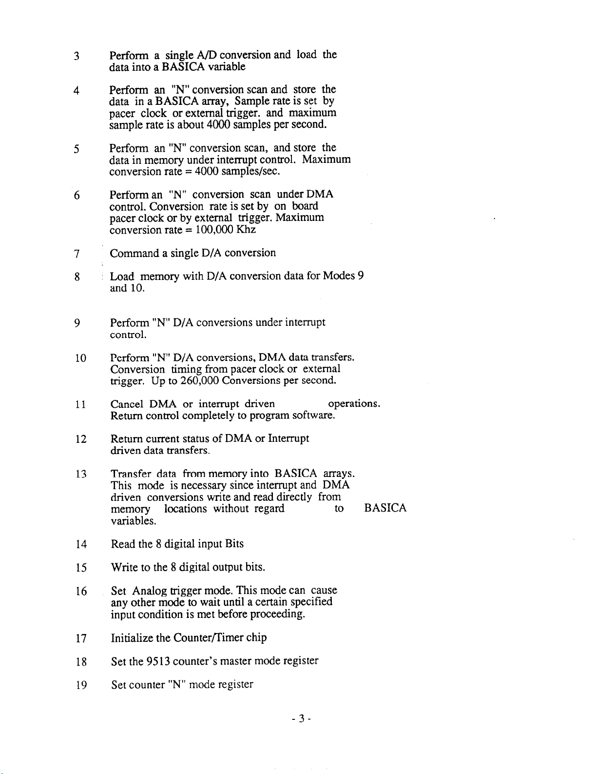
3
Perform a single A/D conversion and load the
data into a BASICA variable
4
5
6
7
8
9
10
Perform an “N” conversion scan and store the
data in a BASICA array, Sample rate is set by
pacer clock or external trigger. and maximum
sample rate is about 4000 samples per second.
Perform an “N” conversion scan, and store the
data in memory under interrupt control. Maximum
conversion rate = 4000 samples/set.
Perform an “N” conversion scan under DMA
control. Conversion rate is set by on board
pacer clock or by external trigger, Maximum
conversion rate = 100,000 Khz
Command a single D/A conversion
: Load memory with D/A conversion data for Modes 9
and 10.
Perform “N” D/A conversions under interrupt
control.
Perform “N” D/A conversions, DMA data transfers.
Conversion timing from pacer clock or external
trigger. Up to 260,000 Conversions per second.
11
12
13
14
15
16
17
18
19
Cancel DMA or interrupt driven operations.
Return control completely to program software.
Return current status of DMA or Interrupt
driven data transfers.
Transfer data from memory into BASICA arrays.
This mode is necessary since interrupt and DMA
driven conversions write and read directly from
memory locations without regard
variables.
Read the 8 digital input Bits
Write to the 8 digital output bits.
Set Analog trigger mode. This mode can cause
any other mode to wait until a certain specified
input condition is met before proceeding.
Initialize the Counter/Timer chip
Set the 95 13 counter’s master mode register
Set counter “N” mode register
to BASICA
-3-
Page 9
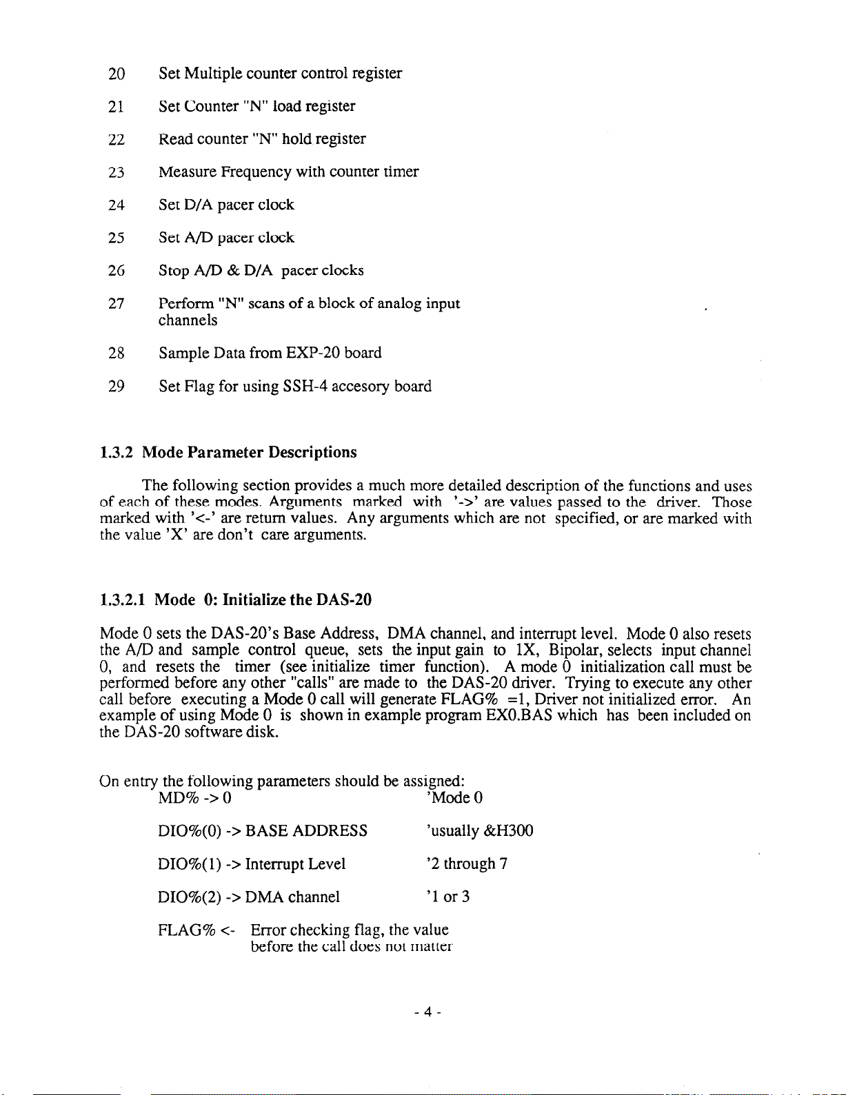
20
Set Multiple counter control register
21
22
23
24
25
26
27
28
29
Set Counter “N” load register
Read counter “N” hold register
Measure Frequency with counter timer
Set D/A pacer clock
Set A/D pacer clock
Stop A/D & D/A pacer clocks
Perform “N” scans of a block of analog input
channels
Sample Data from EXP-20 board
Set Flag for using SSH-4 accesory board
1.3.2 Mode Parameter Descriptions
The following section provides a much more detailed description of the functions and uses
of each of these modes. Arguments marked with
marked with ‘<-’ are return values. Any arguments which are not specified, or are marked with
the value ‘X’ are don’t care arguments.
‘->’ are values passed to the driver. Those
1.3.2.1 Mode 0: Initialize the DAS-20
Mode 0 sets the DAS-20’s Base Address, DMA channel, and interrupt level. Mode 0 also resets
the A/D and sample control queue, sets the input gain to 1X, Bipolar, selects input channel
0, and resets the timer (see initialize timer function).
performed before any other “calls” are made to the DAS-20 driver. Trying to execute any other
call before executing a Mode 0 call will generate FLAG% =l, Driver not initialized error.
example of using Mode 0 is shown in example program EXO.BAS which has been included on
the DAS-20 software disk.
On entry the following parameters should be assigned:
MD% -> 0
DIO%(O) -> BASE ADDRESS
DIO%( 1) -> Interrupt Level
DI0%(2) -> DMA channel
FLAG% <-
Error checking flag, the value
before the call does not matter
‘Mode 0
‘usually &H300
‘2 through 7
‘1 or3
A mode 0 initialization call must be
An
-4-
Page 10
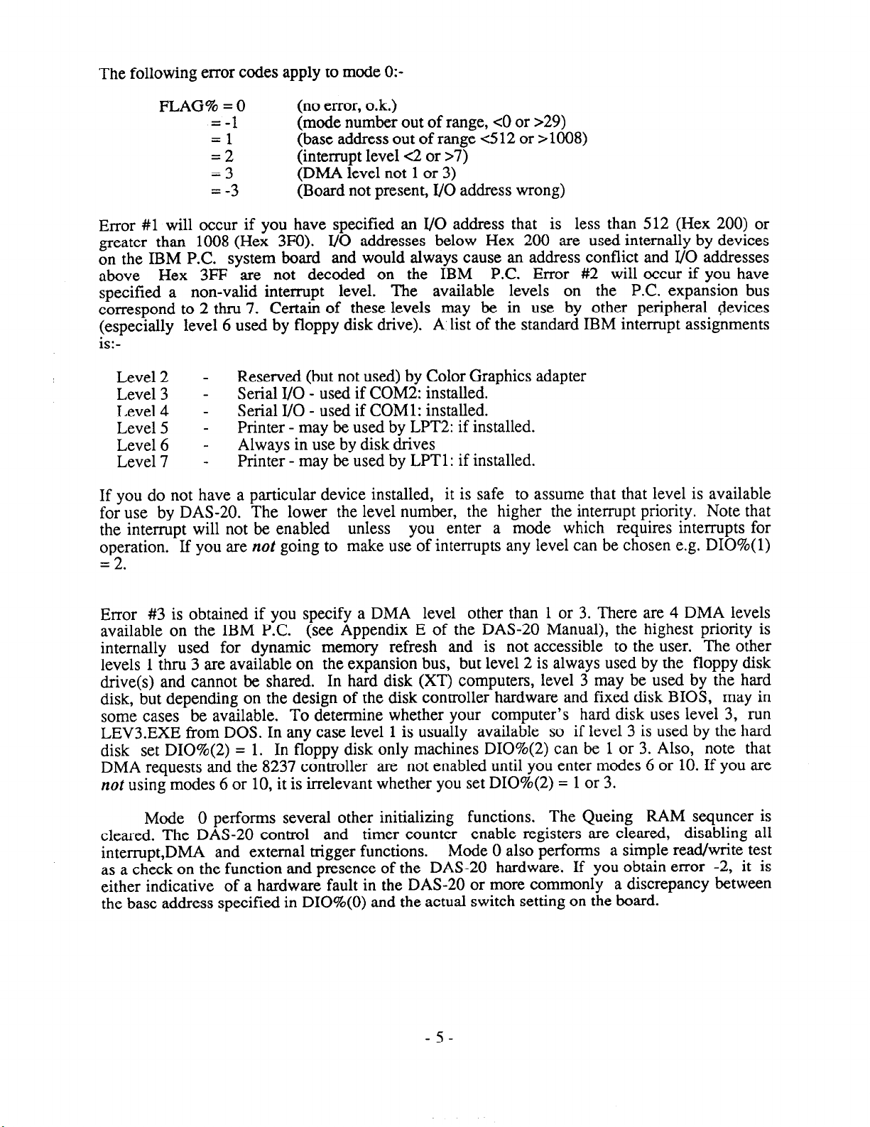
The following error codes apply to mode O:-
FLAG% = 0
Error #l will occur if you have specified an I/O address that is less than 512 (Hex 200) or
greater than 1008 (Hex 3FO). I/O addresses below Hex 200 are used internally by devices
on the IBM P.C. system board and would always cause an address conflict and I/O addresses
above Hex 3FF are not decoded on the IBM P.C. Error #2 will occur if you have
specified a non-valid interrupt level.
correspond to 2 thru 7. Certain of these levels may be in use by other peripheral devices
(especially level 6 used by floppy disk drive). A,list of the standard IBM interrupt assignments
is:-
Level 2 Level 3 Level 4 Level 5 Level 6 Level 7 -
If you do not have a particular device installed, it is safe to assume that that level is available
for use by DAS-20. The lower the level number, the higher the interrupt priority. Note that
the interrupt will not be enabled unless you enter a mode which requires interrupts for
operation. If you are not going to make use of interrupts any level can be chosen e.g. DIO%( 1)
= 2.
=-
1 (mode number out of range, <O or >29)
=
=:.
=3
=
-3 (Board not present, I/O address wrong)
Reserved (but not used) by Color Graphics adapter
Serial I/O - used if COM2: installed.
Serial I/O - used if COMl: installed.
Printer - may be used by LPT2: if installed.
Always in use by disk drives
Printer - may be used by LPTl: if installed.
(no error, o.k.)
(base address out of range 412 or >1008)
(interrupt level <2 or >7)
(DMA level not 1 or 3)
The available levels on the P.C. expansion bus
Error #3 is obtained if you specify a DMA level other than 1 or 3. There are 4 DMA levels
available on the IBM P.C. (see Appendix E of the DAS-20 Manual), the highest priority is
internally used for dynamic memory refresh and is not accessible to the user. The other
levels 1 thru 3 are available on the expansion bus, but level 2 is always used by the floppy disk
drive(s) and cannot be shared. In hard disk (XT) computers, level 3 may be used by the hard
disk, but depending on the design of the disk controller hardware and fixed disk BIOS, may in
some cases be available. To determine whether your computer’s hard disk uses level 3, run
LEV3.EXE from DOS. In any case level 1 is usually available so if level 3 is used by the hard
disk set DI0%(2) = 1. In floppy disk only machines DI0%(2) can be 1 or 3. Also, note that
DMA requests and the 8237 controller are not enabled until you enter modes 6 or 10. If you are
not using modes 6 or 10, it is irrelevant whether you set DI0%(2) = 1 or 3.
Mode 0 performs several other initializing functions. The Queing RAM sequncer is
cleared. The DAS-20 control and timer counter enable registers are cleared, disabling all
interrupt,DMA and external trigger functions.
as a check on the function and presence of the DAS-20 hardware. If you obtain error -2, it is
either indicative of a hardware fault in the DAS-20 or more commonly a discrepancy between
the base address specified in DIO%(O) and the actual switch setting on the board.
Mode 0 also performs a simple read/write test
-5-
Page 11
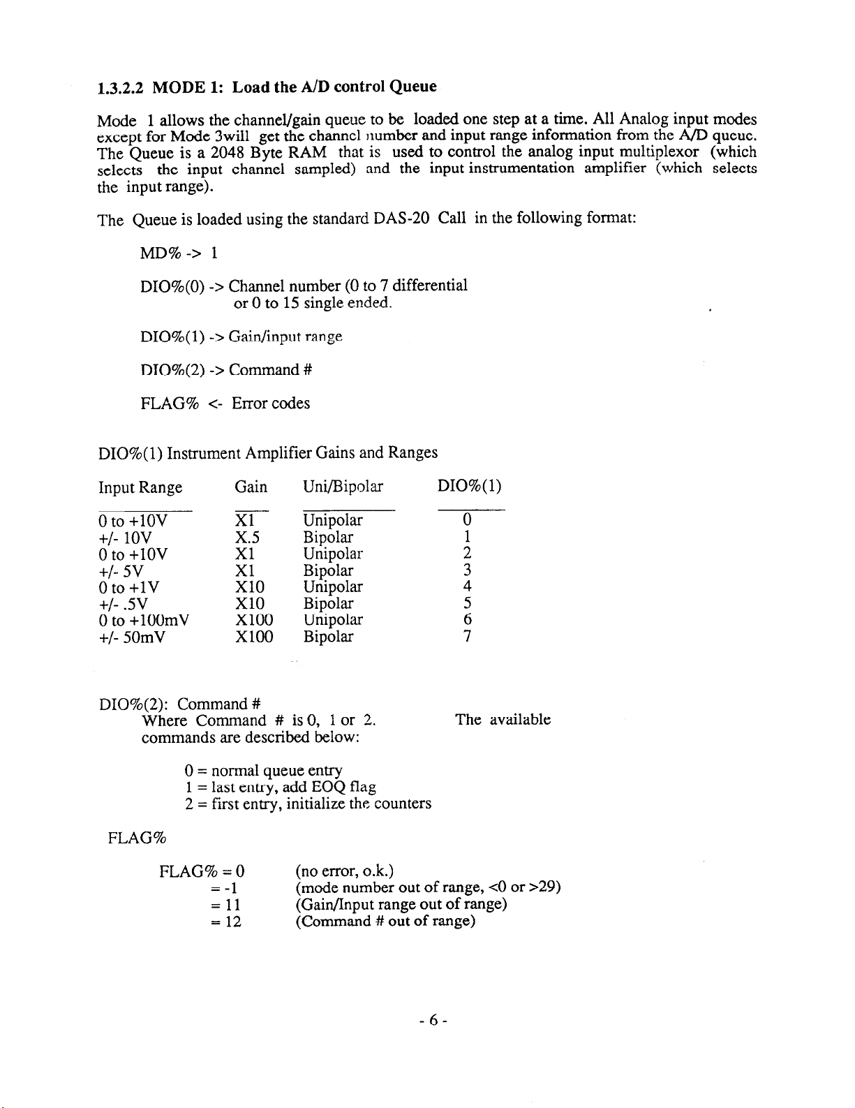
1.3.2.2 MODE 1: Load the A/D control Queue
Mode 1 allows the channel/gain queue to be loaded one step at a time. All Analog input modes
except for Mode 3will get the channel number and input range information from the AfD queue.
The Queue is a 2048 Byte RAM that is used to control the analog input multiplexor (which
selects the input channel sampled) and the input instrumentation amplifier (which selects
the input range).
The Queue is loaded using the standard DAS-20 Call in the following format:
MD%-> 1
DIO%(O) -> Channel number (0 to 7 differential
or 0 to 15 single ended.
DIO%( 1) -7 Gain/input range
DI0%(2) -7 Command #
FLAG% c- Error codes
DIO%( 1) Instrument Amplifier Gains and Ranges
Input Range Gain
0 to
+lOV
+/- 1ov
0
to +lOV
+/- 5v
0 to
+lV
+/- .5v
0
to +lOOmV
+/- 50mV
DI0%(2): Command #
Where Command # is 0, 1 or 2.
commands are described below:
0 = normal queue entry
1 = last entry, add EOQ flag
2 = first entry, initialize the counters
FLAG%
FLAG% = 0
=-
1
= 11
= 12
Xl
x.5
Xl
Xl
x10
x10
Xl00
x100
Urn/Bipolar DIO%( 1)
Unipolar
Bipolar
Unipolar
Bipolar
Unipolar
Bipolar
Unipolar
Bipolar
The available
(no error, o.k.)
(mode number out of range, <O or 729)
(Gain/Input range out of range)
(Command # out of range)
-6-
Page 12

The first entry (when DI0%(2) is 2) automatically re-initializes the DAS-20 counters, The
second and subsequent (DI0%(2)
entry (DI0%(2)
and reading the sampling
= 1) automatically inserts an EOQ (End Of Queue) bit. An example of loading
Queue has been provided on the DAS-20 software disk.
= 0) entries simply load the queuing RAM, while the final
1.3.2.3 MODE 2: View the current queue
Mode 2 allows the current RAM Queue to be read. When DIO%(2) is 0, the Queue pointer is
automatically incremented after the read so that the next read will be of the next Queue location.
To reset the Queue pointer to 0, issue the same call with DI0%(2) = 1. An exampleof loading
and reading the Queue has been provided in the EXl.BAS program included on the DAS-20
disk.
Arguments:
MD% -7 2
DIO%(O) <- channel number
DIO%(l) c- Gain
DI0%(2) -7 Command #
DI0%(2) <- EOQ condition
Where “Command #” operates as follows:
0 = get next queue command
2 = reset and return to first command in the
queue
On Return, DI0%(2) will be:
,O -- End of Queue bit not set
--
1
End of Queue bit set
FLAG% <- Errors
0 = (No Error)
-1 = (Mode # out of Range)
1 = (Gain out of range)
2 = (Command # out of range)
1.3.2.4 MODE 3: Perform a Single A/D Conversion
Initialize the A/D converter, set the channel and input range desired, wait for completion, and
return data. Note that this is the only mode that does not perform conversions based on the
Queuing RAM.
- 7 -
Page 13
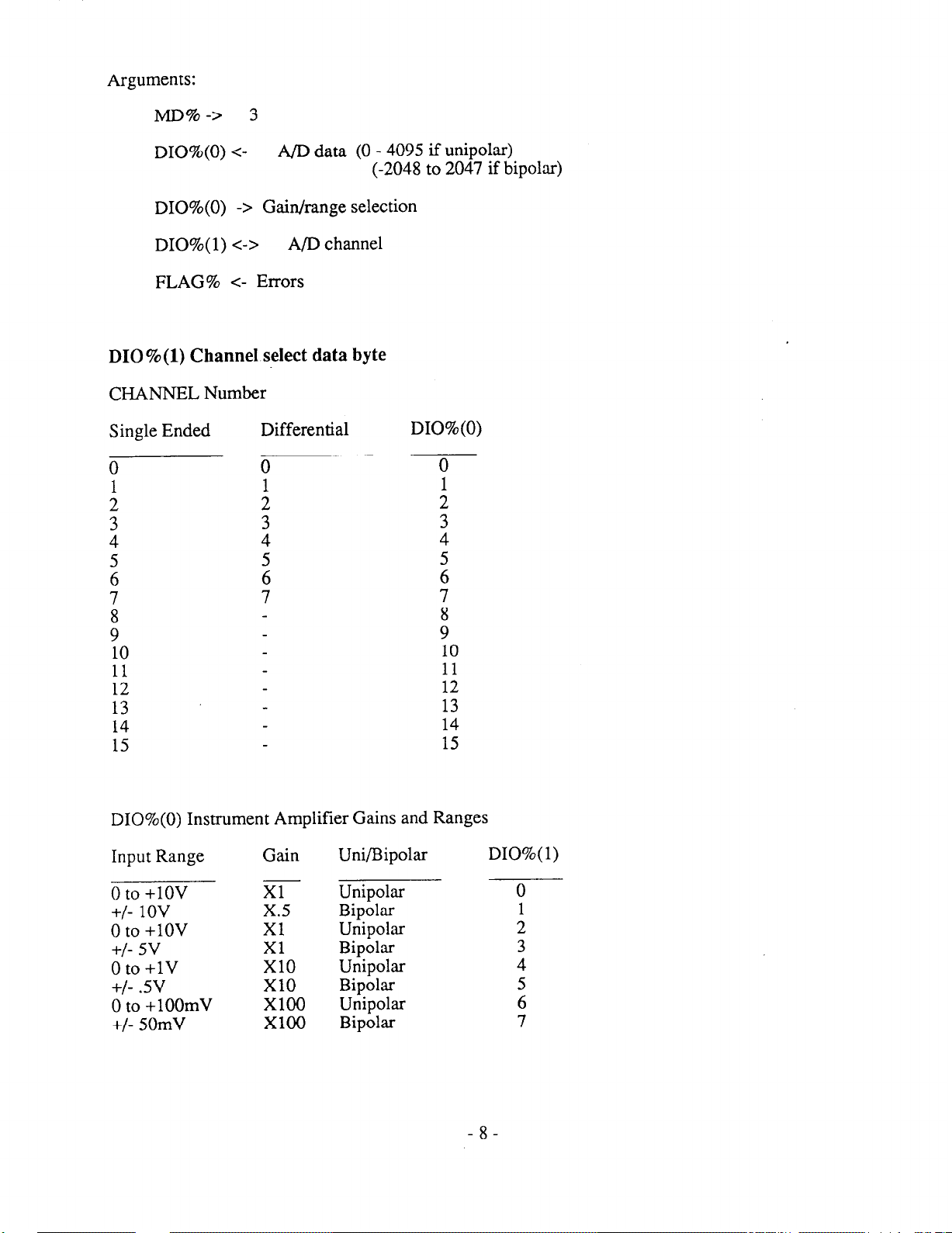
Arguments:
MD%-7 3
DIO%(O) <-
DIO%(O) -7 Gain/range selection
DIO%( 1) c-7 A/D channel
FLAG% <- Errors
A/D data (0 - 4095 if unipolar)
(-2048 to 2047 if bipolar)
010%(l) ChanneI select data byte
CHANNEL Number
Single Ended
0
1
;
Differential
0
4
5
6
7
t
10
DIO%(O)
0
1
i
4
z
7
8
9
10
::.
13
14
15
DIO%(O) Instrument Amplifier Gains and Ranges
Input Range
0 to +lOV
+/- 1ov
0 to +lOV
+/- 5v
0 to +lV
+/- .5v
0 to +lOOmV
+/- 50mV
Gain
Xl
x.5
Xl
EO
x10
x100
x100
Uni/Bipolar DIO%( 1)
Unipolar 0
Bipolar
Unipolar
Bipolar
Unipolar
Bipolar
Unipolar
Bipolar
-8-
1
2
3
4
5
6
7
Page 14
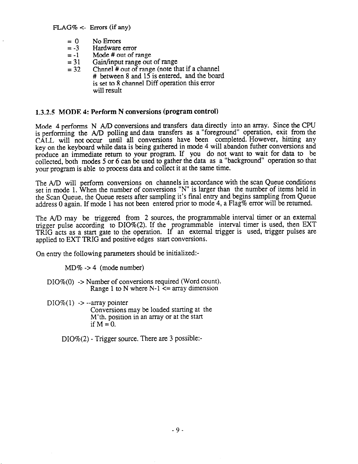
FLAG% <- Errors (if any)
=
=
-! Hardware error
=,311
= 32
No Errors
Mode # out of range
Gain/input range out of range
Chnnel # out of range (note that if a channel
# between 8 and 15 is entered, and the board
is set to 8 channel Diff operation this error
will result
1.3.2.5 MODE 4: Perform N conversions (program control)
Mode 4 performs N A/D conversions and transfers data directly into an array. Since the CPU
is performing the A/D polling and data transfers as a “foreground” operation, exit from the
CALL will not occur until all conversions have been completed. However, hitting any
key on the keyboard while data is being gathered in mode 4 will abandon futher conversions and
produce an immediate return to your program. If you do not want to wait for data to be
collected, both modes 5 or 6 can be used to gather the data as a “background” operation so that
your program is able to process data and collect it at the same time.
The A/D will perform conversions on channels in accordance with the scan Queue conditions
set in mode 1. When the number of conversions “N” is larger than the number of items held in
the Scan Queue, the Queue resets after sampling it’s final entry and begins sampling from Queue
address 0 again. If mode 1 has not been entered prior to mode 4, a Flag% error will be returned.
The A/D may be triggered from 2 sources, the programmable interval timer or an external
trigger pulse according to DI0%(2). If the programmable interval timer is used, then EXT
TRIG acts as a start gate to the operation.
If an external trigger is used, trigger pulses are
applied to EXT TRIG and positive edges start conversions.
On entry the following parameters should be initialized:-
MD% -> 4 (mode number)
DIO%(O) -7 Number of conversions required (Word count).
Range 1 to N where N-l c= array dimension
DIO%( 1) -7 --array pointer
Conversions may be loaded starting at the
M’th. position in an array or at the start
if M = 0.
DI0%(2) - Trigger source. There are 3 possible:-
-9-
Page 15
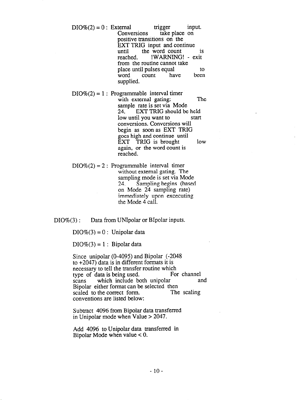
DI0%(2) = 0 : External
Conversions
positive transitions on the
EXT TRIG input and continue
until
reached.
from the routine cannot take
place until pulses equal
word count
supplied.
DI0%(2) = 1 : Programmable interval timer
with external gating:
sample rate is set via Mode
24.
low until you want to
conversions. Conversions will
begin as soon as EXT TRIG
goes high and continue until
EXT TRIG is brought
again, or the word count is
reached.
DI0%(2) = 2 : Programmable interval timer
without external gating. The
sampling mode is set via Mode
24.
on Mode 24 sampling rate)
immediately upon excecuting
the Mode 4 call.
EXT TRIG should be held
Sampling begins (based
trigger
take place on
the word count *
!WARNING! - ex?
have
input.
be:
The
start
low
DI0%(3) :
DI0%(3) = 0 : Unipolar data
DI0%(3) = 1 : Bipolar data
Since unipolar (o-4095) and Bipolar (-2048
to +2047) data is in different formats it is
necessary to tell the transfer routine which
type of data is being used.
scans
Bipolar either format can be selected then
scaled to the correct form.
conventions are listed below:
Subtract 4096 from Bipolar data transferred
in Unipolar mode when Value 7 2047.
Add 4096 to Unipolar data transferred in
Bipolar Mode when value < 0.
Data from UNIpolar or Bipolar inputs.
For channel
which include both unipolar
The scaling
and
- lo-
Page 16
The following error codes apply to mode 4:-
FLAG% = 0 (no error, o.k.)
=
-2 (driver not initialized)
=
-1 (mode number out of range, <O or 729)
= 41
= 43 (trigger mode not 0 or 1)
(number of conversions 0 or negative)
1.3.2.6 MODE 5: Multiple A/D conversions-- Interrupt driven
Mode 5 performs N A/D conversions triggered either externally or by the programmable
timer. At the end of each conversion, an interrupt is generated that invokes an interrupt handler
routine installed by this mode. This routine transfers the data from each conversion to a
specified segment of memory and keeps track of the total number of conversions performed.
When the number reaches N, as specified by DIO%(O), interrupts are disabled if in the nonrecycle mode (DI0%(3)=0), or the process is repeated continuously to the same segment of
memory if DI0%(3) specifies the recycle mode. Note that once mode 5 has enabled interrupts,
conversions continue regardless of what other programs the user may be running (although
they should not interfere either with the location of the DAS20.BIN driver or the A/D data
area). For this reason it is termed a background operation and in most respects is
functionally similar to mode 6 (D.M.A.) although much slower. About 3000 samples/set. are
possible in mode 5.
The A/D will perform conversions on channels in accordance with the scan Queue that must
be set by mode
1. When the number of conversions “N” is larger than the number of items held in the Scan
Queue, the Queue resets after sampling it’s final entry and begins sampling from Queue address
0 again.
The A/D may be triggered from 2 sources, the programmable interval timer or an external
trigger pulse according to DI0%(2). If the programmable interval timer is used, then EXT
TRIG acts as a start gate to the operation. If an external trigger is used, trigger pulses are
applied to EXT TRIG, positive edges start conversions.
On entry the following parameters should be initialized:-
MD% -7 5 (mode number)
DIO%(O) = Number of conversions required (Word count).
Range 1 to N, where N can range from 1 to
32766.
items in the sample Queue,
automatically resets the Queue pointer, and
continues sampling.
DIO%( 1) = Segment of
When N is larger than the number of
the program
memory to
receive
data.
- ll-
Page 17

DI0%(2) - Trigger source. There are 3 possible:-
DI0%(2) = 0 : External
Conversions take place
positive transitions on the
EXT TRIG input and continue
until
reached.
DI0%(2) = 1 : Programmable interval timer
with external gating:
sample rate is set via Mode
24.
low until you want to
conversions. Conversions will
begin as soon as EXT TRIG
goes high and continue until
EXT TRIG is brought
again, or the word count is
reached.
DI0%(2) = 2 : Programmable interval timer
without external gating. The
sampling mode is set via Mode
24.
on Mode 24 sampling rate)
immediately upon excecuting
the Mode 5 call.
EXT TRIG should be held
Sampling begins (based
trigger
the word count is
input.
on
The
start
low
Since Mode 5 is a background task, the foreground program may stop the A/D collection
at any time by executing a Mode 11 call. If the Mode 5 operation is being internally paced,
Mode 26 (stop A/D clock) should also be called.
DI0%(3) - Single cycle/Re-cycle operation:-
DI0%(3) = 0 : Re-cycle. In this case data
is continuously written to
DIO%(O)
stopped by
the
DI0%(3) = 1 : One cycle. After completion
DI0%(4) = X
FLAG% = X
the same memory.
corresponds to the memory
“buffer” length. The status
of the operation is 1 =
active
mode 11.
of the number of conversions
specified,
disabled,
operation status to zero.
(value does not matter)
(value does not matter)
until
interrupts are
setting
- 12-
Page 18

The following error codes apply to mode 5:-
FLAG% = 0
=
-2
=
-1 (mode number out of range, CO or 729)
= 50 (Interrupt or D.M.A. already active)
=51 (number of conversions 0 or negative)
= 53 (Trigger input out of range)
=54
(no error, o.k.)
(driver not initialized)
(Recycle flag not 0 or 1)
1.3.2.7 MODE 6: Multiple A/D samples with DMA data transfer.
Mode 6 performs “N” A/D conversions triggered either externally or by the programmable
timer, and at the end of each conversion, a direct memory transfer from the A/D to memory is
performed under the control of the IBM P.C. 8237 D.M.A. controller. This device transfers
the data from each conversion to a specified segment of memory and keeps track of the total
number of conversions performed without involving the 8088 CPU. When the number reaches
N, as specified by DIO%(O), D.M.A. transfers cease and a terminal interrupt is generated if in
the non-recycle mode (DI0%(3), or D.M.A. transfers are repeated continuously to the same
segment of memory if DI0%(3) specifies the re-cycle (auto-initialize) mode. Note that once
mode 6 has enabled D.M.A., conversions continue regardless of what other programs the user
may be running.
background operation and is extremely fast. Throughput is limited by the speed of the A/D
converter and settling of the sample hold. Using the Harris HI-774 A/D converter, the DAS-20
can sustain a throughput slightly in excess of 100,ooO samples/set. A technical description of
the IBM P.C. D.M.A. arrangements is contained in Appendix E of the DAS-20 Manual.
D.M.A. is performed purely by the system and DAS-20 hardware, is a
The A/D will perform conversions on channels in accordance with the scan Queue set in mode
1. When the number of conversions “N” is larger than the number of items held in the Scan
Queue,
address 0 again. If mode 1 has not been entered prior to mode 6, a FLAG% error will be
generated and no conversions will be performed.
the Queue resets after sampling it’s final entry and begins sampling from Queue
NOTE: The DAS-20’s input instrumentation amplifier has been designed for low noise,
high gain, and high speed performance.
However, in order to minimize noise at high
gains, the input bandwidth has been reduced. To assure accurate readings the following
maximum sample rates at higher gains should be observed.
Input Range
Oto 1ov
-t/- 10 v
+/- 5 v
o-1 v
+/- 0.5 v
Oto 1OOmV
+/-50 mV
Maximum Recommended
sample rate
100,000 samples/set
100,000 samples/set
100,000 samples/set
80,000 samples/set
80,000 samples/set
40,000 samples/set
40,000 samples/set
- 13-
Page 19

On entry the following parameters should be initialized:-
MD% -7 6 (modenumber)
DIO%(O) -7 Number of conversions required (Word count).
Range 1 to N, where N can range from 1 to
32766. When N is larger than the number of
items in the sample Queue, the program
automatically resets the Queue pointer, and
continues sampling.
DIO%( 1) -7 Segment of memory to receive data.
DI0%(2) -7 Trigger source. There are 3 possible:-
DI0%(2) = 0 : External trigger input.
Conversions take place on
positive transitions on the
EXT TRIG input and continue
until the word count is
reached.
DI0%(2) = 1 : Programmable interval timer
with external gating: The
sample rate is set via Mode
24.
EXT TRIG should be held
low until you want to start
conversions. Conversions will
begin as soon as EXT TRIG
goes high and continue until
EXT TRIG is brought low
again, or the .word count is
reached.
DI0%(2) = 2 : Programmable interval timer
without external gating. The
sampling mode is set via Mode
24.
Sampling begins (based
on Mode 24 sampling rate)
immediately upon excecuting
the Mode 6 call.
Since Mode 6 is a background task, the foreground program may stop the A/D collection at
any time by executing a Mode 11 call. If the Mode 5 operation is being internally paced, Mode
26 (stop A/D clock) should also be cal.led.
- 14-
Page 20

DI0%(3) -7 Single cycle/Recycle operation:-
DI0%(3) = 0 : Re-cycle. In this case data
is continuously written to
the same memory.
corresponds to the memory
“buffer”
corresponds
auto-initialize
To end the acquisition, mode
11 must be run.
DI0%(3) = 1 : One cycle. After completion
of the number of conversions
specified, DMA ceases, an
interrupt is generated and
DMA is disabled, setting the
DMA status to zero.
length.
to
DIO%(O)
This
a D.M.A.
operation.
DI0%(4) = X
The following error codes apply to mode 6:-
FLAG% = 0
=
1
==6;
= 61
= 63
Several details apply to the reliable use of mode 6. First, you cannot re-run mode 6 if a mode 5
interrupt or a previous mode 6 D.M.A. operation is still active. Error #60 will result. If you
request the recycle mode which generates continuous D.M.A. transfers, then mode 11 which
disables D.M.A. and interrupts must be run before you can succesfully run mode 6 again. If you
are in non-recycle mode, then it must have reached the word count which automatically disables
D.M.A. before mode 6 can be run again.
D.M.A. request (DRQ) drivers of the DAS-20 are placed in the high impedance state. This
allows more than one hardware device, or multiple DAS-20’s to use the same D.M.A. level as
long as they do so sequentially.
Second, since the D.M.A. page registers
maximum data area available is 64K (a page) for 32,767 conversions. Be sure that your data
area is not in use by your program or altered by subsequent operations. Also be careful that
your word count added to your segment will not cross a page boundary. This condition
which would otherwise cause a wrap round to the beginning of the page is detected by the
driver and produces error #67. To avoid this, a conservative rule is to use a segment that is also
a page boundary e.g. &HlOOO, &H2000 etc. Data may be retrieved using mode 13 during or
after the operation of mode 6 and mode 13 will not alter the memory.
(no error, o.k.)
(driver not initialized)
(mode number out of range, <O or 729)
(Interrupt or D.M.A. already active)
(number of conversions 0 or negative)
(Trigger out of range)
(value does not matter)
On completion of a D.M.A. operation, the n-i-state
cannot be incremented by the controller, the
Note that once DMA operation is initiated, it may well continue during or following execution
of the program. This
is a “background” operation.
- 15-
Strange effects can occur if you
Page 21

inadvertently transfer data into your program area,
be sure to use a free area of memory for
your DMA buffer. DEBUG can help you locate free areas, they are usually loaded with zeroes
on boot-up.
If you require to transfer more data than can be held in one 64K data segment, MetraByte is
currently in development of an optional data streamer software (STREAM-16) which has
been specially devised to perform continuous transfer through a D.M.A. buffer to hard disk.
With this software it is possible to continuosly stream “gapless” data to your hard disk at more
than 5OKHz on a PC/AT (somewhat slower on an XT). A standard 20 Megabyte hard disk will
hold about 3 minutes of data at 5OKHz. The maximum speeds attainable are dependent on the
type of your disk controller and manufacturer of your hard disk - contact MetraByte for
further information. Call MetraByte for availablility information on the STREAM- 16 package.
1.3.2.8 MODE 7: Command a Single D/A conversion
Mode 7 performs a write to one of the D/A converters.
MD% -7 7
DIO%(O) -7 D/A channel (0 or 1)
DIO%( 1) -7 D/A data (0 - 4095 for unipolar)
(-2048 to 2047 for Bipolar)
FLAG% = 0 (no error, o.k.)
=
=-
=71
1
1
(driver not initialized)
(mode number out of range, <O or 729)
(D/A channel # not 0 or 1)
= 72 (D/A data out of range, <O or >4095)
1.3.2.9 MODE 8: Load Memory Segment for D/A conversion.
Mode 8 has been developed to allow the user to load a segment of memory in preparation
for writing the data out to the DAS-20 D/A converters. Each conversion requires two bytes
of memory to be stored. This allows up to 32,768 conversions (single D/A), or 16,384
conversions (both D/A’s) to be loaded into a 64 KiloByte page of memory.
Arguments:
MD%-7 8
DIO%(O) ->
DIO%(l) -7
Number of Data words (conversions)
to transfer.
Memory Segment Address for raw data
- 16-
Page 22

DI0%(2) -7
Starting offset for entering data
into the raw data buffer. DI0%(2)
will usually be 0, and the first
data word will be written into the
first buffer location.
some instances, when data is being
taken from more than one array, it
is necessary to load one array into
memory,
immediately following the first.
then load another array
However, in
DI0%(3) ->
FLAG% <- Errors
FLAG% = 0
Pointer to array containing
the data to write to the D/As.
may be found by executing
(no error, o.k.)
(driver not initialized)
(mode number out of range, ~0 or 729)
(Word count zero or >32766)
(Segment address out of range)
(Start offset out of range)
(Data pointer out of range)
=
=-
=8;
=81
1;;
pointer
the following instructions:
1
The
1.3.2.10 MODE 9: Multiple Interrupt D/A conversions
Mode 9 performs “N” D/A conversions based on interrupt control. Data is read directly
from memory (loaded by Mode 8) and written to the D/A converters. If Mode 8 was set to
load data for both D/A’s than Mode 9 must also select two channel operation. However, if Mode
8 only loaded data for one D/A channel,
update rate for D/A conversions can be set with Mode 25, or by an external signal.
Mode 9’s channel select can select either D/A. The
The following variables are defined by Mode 9:
MD% -> 9
DIO%(O) -7 Number of conversions
DIO%( 1) -7 Segment address of buffer
- 17-
Page 23
DI0%(2) -> Trigger source:
DI0%(2) = 0
DI0%(2) = 1
DI0%(2) = 2
DI0%(3) -7 Recycle flag
0 = restart on Nth conversion
X = terminate on X* cycle of
N conversions.
DI0%(4) -7 Channel select
0 = channel 0
1 = channel 1
2 = both channels
External trigger.
conversion is started on each
rising edge of the DAC TRIG
pin. (pin 29)
Internal Trigger w/ external
gating.
initiated based on the clock
rate set in Mode 25, and
gated by the EXT GATE pin.
Internal
external
conversion is initiated based
on the Mode 25 clock rate.
A D/A
A conversion is
Trigger without
gating.
A
FLAG% <- Error Codes
FLAG% = 0
=
1
.
=
=&
=91
=92
= 93
= 94
= 95
(no error, o.k.)
(driver not initialized)
(mode number out of range, <O or 729)
(Interrupt already active)
(Word count zero or 732767)
(Buffer address out of range)
(Trigger source not 0, 1, or 2)
(Recycle flag out of range)
(D/A channel not 0,l or 2)
1.3.2.11 MODE 10: DMA driven D/A conversions
Mode 10 performs
directlv from memory (loaded by Mode 8) and written to the D/A converters. If Mode 8 was set
to load data for both D/A’s than Mode 10 must also select two channel operation. However,
if Mode 8 only loaded data for one D/A channel,
select either channel 0 or 1.
The update rate of the D/A conversions can be set by the internal pacer clock (and Mode 25) or
can be synchronized to an external trigger.
“N” D/A conversions based on DMA data transfers. Data is read
Mode 10’s channel select control can
- 18-
Page 24

The following variables are defined by Mode 10:
MD% -> 10
DIO%(O) -> Number of conversions
DIO%( 1) -> Segment address of buffer
DI0%(2) -> Trigger source:
DI0%(2) = 0
DI0%(2) = 1
DI0%(2) = 2
DI0%(3) -> Recycle flag
0 = restart on Nth conversion
X = terminate on P cycle of
N conversions.
DI0%(4) -> Channel select
0 = channel 0
1 = channel 1
2 = both channels
External trigger. A D/A
conversion is started on each
rising edge of the DAC TRIG
pin. (pin 29)
Internal Trigger w/ external
gating. A conversion
initiated based on the clock
rate set in Mode 25, and
gated by the EXT GATE pin.
Internal Trigger without
external gating. A
conversion is initiated based
on the Mode 25 clock rate.
is
FLAG% c- Error Codes
FLAG% = 0
=
1
== lb0
=
101
= 102
= 103
= 104
= 105
(no error, o.k.)
(driver not initialized)
(mode number out of range, <O or >20)
(Interrupt already active)
(Word count zero or >32767)
(Buffer address out of range)
(Trigger source not 0, 1, or 2)
(Recycle flag out of range)
(D/A channel not 0,l or 2)
- 19-
Page 25

1.3.2.12 MODE 11: Cancel DMA or Interrupt
Mode 11 causes an immediate disable of any rurl.ling interrupt or D.M.A. operation
initiated by modes 5,6,9 or 10. The operation will be abandoned at the time mode 11 executes.
On entry the following parameters should be initialized:-
MD%-> 11
DIO%(O) -> X (where X = any value)
FLAG% <- Errors (if any)
The following error codes apply to mode 11:
FLAG% = 0
=-
1
(no error, o.kJ
(mode number out of range, ~0 or >29)
1.3.2.13 MODE 12: Determine Status of interrupt/DMA
Mode 12 allows you to monitor the status of a background operation initiated by modes
5, 6,9 or 10.
Arguments:
MD% -> 12
DIO%(O) c- operation type in progress
0 - none
l-DMA,
2 - interrupt,
DIO%( 1) <- status of operation
0 - Done (finished)
1 - Active
DI0%(2) <- current word count
Number of conversions so far
The following. error codes apply to mode 12:-
FLAG% = 0
=
=-
-2
(no error)
(driver not initialized)
(mode number out of range, ~0 or >27)
1
- 20 -
Page 26

1.3.2.14 MODE 13: Transfer data from memory to array
Mode 13 transfers data from any segment of memory to integer array variables. Data in
memory derived from modes 5, 6 and 27 is in packed form consisting a word (2 bytes) of A/D
data + channel number.
Note how mode 13 functions. The number of words (or conversions) that you wish to transfer
to the data and channel arrays is set into DIO%(O). The segment of memory that you wish to
transfer data from is set into DIO%(l). Data can be transferred from the beginning of this
segment (DI0%(2) = 0) or any other point. A/D data is transferred to a dimensioned integer
array. The transfer will start at the pointer set into DI0%(3).
A/D data is shifted and also the MSB complimented if the DAS-20 is operating in bipolar mode.
In unipolar mode data ranges from 0 to 4095, in bipolar -2048 to +2047. The channel data is
masked out and ranges from 0 - 15.
Note that you must be careful about the transfer parameters. In particular:-
1: Do not transfer more words than an array will hold
or overun the end of the array. No checking is
performed to detect this condition which will
corrupt BASIC workspace and cause strange effects.
2: There is nothing to prevent you transferring
garbage from a source segment that does not
contain A/D data or from overrunning the end of
A/D data. No checking is performed to detect this
condition.
3: Due to the reformatting of data that this mode
performs, it is not a general purpose block move
utility.
On entry the following parameters should be assigned:-
MD% = 13 (mode number)
DIO%(O) -> Number of words to transfer (1 - 32767)
(Number of Scans if DI0%(5) > 0)
DIO%( 1) -> Buffer segment in memory (0 - 65536)
DI0%(2) -> Starting conversion number (0 - 32767)
(Starting Scan # if DI0%(5) > 0)
DI0%(3) -> Array Pointer (data)
DI0%(4) -> Array Pointer (channel)
(set = 0 if no channel data required)
DI0%(5) -> Unipolar/Bipolar Flag.
-2l-
Page 27

= 0 (transfer unipolar data)
= 1 (transfer Bipolar data)
Since unipolar (o-4095) and Bipolar (2048 to +2047) data is in different
formats it is necessary to tell the
transfer routine which type of data is
being used.
include both unipolar and Bipolar either
format can be selected then scaled to the
correct form.
are listed below:
For channel scans which
The scaling conventions
Subtract 4096 from
transferred in Unipolar mode for data > 2047.
Add 4096 to Unipolar data transferred in
Bipolar Mode when value < 0.
DI0%(6) -> SSH-4,Flag. If the input data has been
acquired using the SSH-4, set DI0%(5) to
the number of channels in each scan.
This removes the Dummy first converseion
in each SSH-4 scan. Otherwise, DIO%(O) =
0.
FLAG% = X (value does not matter)
The following error codes apply to mode 13:-
FLAG% = 0
=
-2
== 131 (word count, DIO%(O), zero or negative)
= 132 (buffer Segment out of range)
= 133 (start conversion number, DI0%(2), negative)
= 134 (DI0%(3) out of range)
= 135 (DIO%(4) out of range)
= 136 (SSH-4 Flag out of range)
(no error)
(driver not initialized)
(mode number out of range, CO or >29)
1
Bipolar
data
Once data acquisition has been set up as a constant background operation using the recycle
options of mode 5 or 6, a foreground program can be processing the data as it is acquired using
mode 13 to retrieve the data. This is excellent for graphic and “digital oscilloscope”
applications.
- 22 -
Page 28
1.X2.15 MODE 14: Read the Digital inputs
Mode 14 allows you to read the state of digital inputs DIN0 through DIN7. Data returned
can range between 0 and 255 corresponding to all combinations of the 8 input bits.
On entry the following parameters should be initiaiized:-
MD%=14
DIO%(O thru 4) - value does not matter
FLAG%=X -
On return:
DIO%(O) contains input data (range 0 - 255)
DIO%(l thru 4) - unchanged
The following error codes apply to mode 14:-
FLAG% = 0
=
-2
=
-1
value does not matter
(no error, o.k.)
(driver not initialized)
(mode number out of range, <O or >29)
1.3.2.16 MODE 15: Write to the Digital outputs.
Mode 15 is used to write digital data to the 8 bit output port, DOUTO through DOUT7.
Output data is checked to be in the range 0 - 255 and if not an error exit (error # 151) occurs.
On entry the following parameters shouid be assigned:-
MD%=15
DIO%(O)
DIO%(l thru 4) - value does not matter
The following error codes apply to mode 15:-
FLAG% = 0
=
-2
=
-1
=
151
(no error, o.k.)
(driver not initialized)
(mode number out of range, CO or >29)
(output data ~0 or >255)
- output data (range O-255)
- 23 -
Page 29

1.3.2.17 MODE 16: Analog trigger
Mode 16 provides an analog trigger function similar to an oscilloscope trigger. It is
sometimes useful to wait for a voltage to reach a certain level before starting to ga’&er data
and mode 16 provides this capability. Any of the analog input channels may be designated as a
trigger channel, and you may set the level and slope for triggering. The input range for the
analog triggering mode is always set at _+lO Volts, full scale.
The main use for mode 16 is in front of any of the other data acquisition modes as a gating or
wait loop until the specified analog trigger conditions are met. Since it is possible to get stuck
in the wait loop indefinitely if the trigger conditions are not fulfilled, you can also exit mode 16
by hitting any key which will return you to the calling program.
Parameters DIO%(O) thru DI0%(2) control the triggering and select the trigger channel number,
the trigger level and the
number. It may be one of the scanned channels i.e. within the scan limits and carrying one of the
measured signals,
triggering. The voltage level at which triggering occurs is set by DIO%(l) in bits, ranges of
-2048 to +2047 bits corresponding to bipolar input ranges. The direction of triggering or
slope is controlled by DI0%(2), for instance if DIO%(l) = 1024 on the +/-1Ov range the trigger
level will be +5.OOV and if DI0%(2)
signal exceeds +5.OOV, alternatively if DI0%(2)
place when the trigger signal becomes less than +5.0 Volt.
or a separate channel outside
trigger direction (slope). DIO%(O) specifies the trigger channel
the scanned channels used only for
= 0 (positive slope) triggering will take place when the
= 1 (negative slope) triggering would take
On entry the following variables should be initialized:-
MD%=16
DIO%(O) = Channel number (0- 15)
DIO%( 1) = Trigger level
(-2048 to +2047 bits)
DI0%(2) = Slope (0 = positive, 1 = negative)
DI0%(3) thru DI0%(4) - value irrelevant
The following error codes apply to mode 16:
FLAG% = 0
=
-2
=-
1
= 160
= 161
= 162 (trigger data out of range
= 163
(no error, o.k.)
(driver not initialized)
(mode number out of range, <O or >24)
(Trigger aborted by Keyboard)
(trigger channel out of range)
~2048 or >2047
(slope data not 0 or 1)
- 24 -
Page 30

1.3.2.18 MODE 17: Initialize Timer - Reset timer.
Set counters 3, 4 & 5 to ADC time delays. The AMD9513 counter timer operation are
discussed in much greater detail in chapter 7, and Appendix F of the DAS-20 manual.
Arguments:
MD% -> 17
DIO%(O) -> Don’t Care
FLAG% <-
=o
= -1 (Mode # out of range)
Errors (if any)
(No errors)
1.3.2.19 MODE 18: Set Timer Master Mode Register
Mode 18 sets the AMD9513 to a user specified configuration. Data bus width set to 8
bits, Data pointer
operation are discussed in much greater detail in chapter 7, and Appendix F of the DAS-20
manual.
Arguments:
MD% -> 18
DIO%(O) -> Fout divider ratio (1 - 16)
DIO%(l) -> Fout source
auto increment enabled, Binary division. The AMD9513 counter timer
O=Fl
1 = Source 1
2 = Source 2
3 = Source 3 I
4 = Source 4 I No Connection
5 = Source 5 I
6 = Gate 1
7 = Gate 2
8 = Gate 3 I
9 = Gate 4 I No Connection
10 = Gate 5 I
11 =Fl
12=F2
13=F3
14 = F4
15 =F5
- 25 -
Page 31

DI0%(2) -> Compare 2 disable/enable (O/l)
DI0%(3) -> Compare 1 disable/enable (O/l)
DI0%(4) -> time of day mode control
0 = TOD disabled
1 = TOD Enabled /5 input
2 = TOD Enabled /6 input
3 = TOD Enabled /lO input
FLAG% <- Errors
=o
= -2 (Driver not initialized)
= -1
=
= 182 (DIO%( 1) out of range)
= 183 (DI0%(2) not 0 or 1)
= 184 (DI0%(3) not 0 or 1)
= 185 (DI0%(4) out of range <O or >3)
(No error)
(Mode out or range CO or >29)
18 1 (DIO%(O) out of range)
1.3.2.20 MODE 19: Set Counter ‘N’ Mode Register
Mode 19 sets counter N to to user specified value. The AMD9513 counter timer operation
are discussed in much greater detail in chapter 7, and Appendix F of the DAS-20 manual.
Arguments:
MD% -> 19
DIO%(O) -> Counter Number (1 - 5)
DIO%(l) -> Gating Control (0 - 7)
0 = No gating
1 = Active high level TCN-1
2 = Active high level Gate N+l
3 = Active high level Gate N-l
4 = Active high level Gate N
5 = Active low level Gate N
6 = Active high edge Gate N
7 = Active low edge Gate N
DIO%(2) -> Count Edge positive/negative (O/l)
- 26 -
Page 32

DI0%(3) -> Count Source Selection (0 - 15)
O=TCN-1
1 = Source 1
2 = Source 2
3 = Source 3 I
4 = Source 4 I No Connection
5=Source51
6 = Gate 1
7 = Gate 2
8 = Gate 3 I
9 = Gate 4 I No Connection
10 = Gate 5 I
11 =Fl
12=F2
13=F3
14=F4
15=F5
DI0%(4) -> Disable/Enable special gate (O/l)
DI0%(5) -> Reload from Load/ReIoad from Load
or Hold (O/l)
DI0%(6) -> Count once/Count repetitively (O/l)
DI0%(7) -> Binary counVI3.C.D. count (O/l)
DI0%(8) -> Count down/Count up (O/l)
DI0%(9) -> Output control (0 - 5, except 3)
0 = Inactive
1 = Active high terminal count pulse
2 = Terminal count toggled
3 = *** Illegal ***
4 = Inactive, output high impedence
5 = Active low terminal count pulse
FLAG% c- Errors
FLAG% <- Errors
=
= -2 (Driver not initialized)
= -1
=
= 182 (DIO%(l) out of range CO or >7)
= 183 (DI0%(2) not 0,or 1)
= 184 (DI0%(3) out of range <O or >15)
= 185
= 186
= 187
= 188
= 189
= 180
(No error)
0
(Mode out or range CO or >29)
181 (DIO%(O) out of range cl or >5)
(DI0%(4) not 0 or 1)
(DI0%(5) not 0 or 1)
(DIO%(6) not 0 or 1)
(DI0%(7) not 0 or 1)
(DI0%(8) not 0 or 1)
(DI0%(9) not 0, 1,2,4
or 5)
- 27 -
Page 33

1.3.2.21 MODE 20: Set Multiple Counter Control Registers
- To user specified value. The AMD9513 counter timer operation are discussed in much
greater detail in chapter 7, and Appendix F of the DAS-20 manual.
Arguments:
MD% -> 20
DIO%(O) -> Command (1 - 6)
1 = Arm selected counter
2 = Load source to counter
3 = Load and arm counter
4 = Disarm and save counter
5 = Latch counter to hold register
6 = Disarm counter
DIO%(l) -> Select Counter 1 (O/l)
DI0%(2) -> Select Counter 2 (O/l)
DI0%(3) -> Select Counter 3 (O/l)
DI0%(4) -> Select Counter 4 (O/l)
DI0%(5) -> Select Counter 5 (O/l)
FLAG% <- Errors (if any)
=o (No errors)
= -2 (Driver not initialized)
= -1 (Mode out of range <O or >29)
= 201 (Command # out of range)
= 202 (Select Counter 1 not
= 203 (Select Counter 2
= 204 (Select Counter 3
= 205 (Select Counter 4
= 206 (Select Counter 5
0 or 1)
not 0 or 1)
not 0 or 1)
not 0 or 1)
not 0 or 1)
1.3.2.22 MODE 21: Set Counter ‘N’ Load Register
- To user specified value. The AMD9513 counter timer operation are discussed in much
greater detail in chapter 7, and Appendix F of the DAS-20 manual.
Arguments:
MD% -> 21
DIO%(O) -> 16 bit value
DIO%(l) -> Counter # (1 - 5)
- 28 -
Page 34

FLtGo% <- errors (if any)
(No errors)
= -2 (Driver not initialized)
= -1 (Mode out of range CO or >29)
= 211 (DIO%(O) out of range)
= 212 (counter out of range <l or >5)
1.3.2.23 MODE 22: Read Counter ‘N’ Hold Register
The AMD9513 counter timer operation are discussed in, much greater detail in chapter 7, and
Appendix F of the DAS-20 manual.
Arguments:
MD% -> 22
DIO%(O) <- 16 bit value
DIO%( 1) -> Counter ‘N’ (1 - 5)
FLAG% <- Errors (if any)
=o (No errors)
= -2 (Driver not initialized)
= -1 (Mode out of range <O or >29)
= 221 (DIO%(O) out of range)
= 222 (counter out of range <l or >5)
1.3.2.24 MODE 23: Measure Frequency
Mode 23 returns frequency expressed as cycles per gating interval. The AMD9513
counter timer operation are discussed in much greater detail in chapter 7, and Appendix F of the
DAS-20 manual. The output of CIT # 1, must be physically jumpered to the Gate of C/T # 2 for
proper operation.
Arguments:
MD% -> 23
DIO%(O) -> Gating interval in mS (0 - 32767)
DIO%( 1) -> Select source input signal (1 - 3)
1 = Source 1
2 = Source .2
3 = Gate 1
DI0%(2) <- Count accumulated during gating interval.
- 29 -
Page 35

FLAGo% c- Errors (if any)
=
= -2 (Driver not initialized)
= -1 (Mode out of range <O or >29)
= 231 (DIO%(O) out of range)
= 232 (Input source out of range <I or >4)
(No errors)
1.3.2.25 MODE 24: Set A/D pacer clock
The A/D timer allows the analog outputs to be updated based on the DAS-20’s onboard 5 Mhz clock. The A/D pacer clock uses the AMD-9513 counter chip to divide the 5 Mhz
clock. The board uses 2 of the AMD-9513’s 16 bit counters allowing the 5 Mhz clock to be
divide by any value from 50 to 4.29 E9 (100 Khz to .00116 hz respectivley). The actual
divisor number will be DIVISOR 1, (DIO%(O)) multiplyed by DIVISOR 2, (DIO%(I). To
obtain an update rate of 100 Khz (5 Mhz divided by fifty), enter a divisor of 10 in
DIO%(O) and 5 in DIO%(l), or ( 5 in DIO%(O) and 10 in DIO%( 1)). For 25 Khz use
DIO%(O) = 4, and DIO%(l) = 50 etc. Note that DIO%(O) may be set zero or one if only one
divisor is required.
Arguments:
MD% -> 24
DIO%(O) -> Divisor 1 (50 - 65536)
DIO%(l) -> Divisor 2 (set = to 0)
FLAG% <- Error Codes
=
0 (no errors)
=
-2 (Driver not initialized)
=-
1 (Mode out of range <O or >29)
= 241 (Divisor 1 out of range)
= 242 (Divisor 2 out or range)
1.3.2.26 MODE 25: SET D/A pacer clock
The D/A timer allows the analog outputs to be updated based on the DAS-20’s on-board 5
Mhz clock. The D/A pacer clock uses the AMD-95 13 counter chip to divide the 5 Mhz clock by
any value from 20 to 232 (250 Khz to Once every 14 minutes). Note that Mode 25 is also used
to set the scan rate for Mode 27. The actual divisor is transfered in DIO%(O) and DIO%(l). If
the total divisor is less than 65536 then 010%(l) can be set to 0. The AMD-9513’s counter 2
is set to divide the 5 Mhz by Divisor # 1.
counter 1 is automatically connected to counter 2, and the total division ratio is the 5 Mhz
divided by Divisor 1 multiplied by Divisor 2. To obtain an update rate of 100 Khz, set Divisor #
1 equal to 50, and Divisor # 2 equal to 0. Alternatively you could set Divisor # 1 to 10, and
Divisor # 2 to 5 and obtain the same result. Note that mode 25 uses AMD-9513 channel 2
If Divisor # 2 is not zero, then AMD-95 13
(and channel 1 if Divisor # 2 is not zero). Counter 2 (and 1 if non-zero Divisor # 2) cannot
- 30 -
Page 36

be used for other timing/counting applications while Mode 25 is being used to pace D/A
conversions
Arguments:
MD% -> 25
DIO%(O) -> Divisor # 1 (1 to 65536)
DIO%(l) -> Divisor # 2 (set to = 0)
FLAG% C- Errors (if any)
The following error codes apply to mode 25:
FLAG% = 0
=
-2 (driver not initialized)
=
-1
= 251 (Divisor # 1 out of range)
= 252 (Divisor # 2 out of range)
(no error)
(Mode out or range ~0 or >29)
1.3.2.27 MODE 26: Stop A/D and D/A pacer clocks
Mode 26 can be used to stop either the A/D or D/A pacer clocks. Modes 24 or 25 will
can then be executed to restart the timers.
MD% -> 26
DIO%(O) -> A/D or D/A clock
DIO%(O) = 0, Stop A/D timer
= 1, Stop D/A timer
=2, Both
FLAG% c- Errors
FLAG% = 0 (no error)
=
-2
== 261 @IO%(O)
(driver not initialized)
1 (Mode out or range ~0 or >29)
not 0, 1, or 2)
1.3.2.28 MODE 27: Perform, “N” scans of a block of channels
Mode 27 performs a block scan of channels. On an input trigger (either from the pacer
clock or an external trigger), the entire Sampling Queue is scanned at the DAS-20’s maximum
sample rate, and the input data is transfered to memory via DMA. The board then waits for the
next trigger and repeats the process. The channels sampled must have been previously set with
a Mode 1 call of a Flag% error will result. This function is very useful in applications where it
is important to have all channels sampled at the same time,
-3l-
but when the overall sample rate
Page 37

need not be extremely high. Note that the same memory limitations apply to Mode 27 as to
Mode 6. The memory used by mode 27 is limited to one Page (64 KiloBytes).
In the block mode counters 3, 4, and 5 are used to control the speed of the A/D
conversions once the command to perform a full scan of the Queue has been given. The
counters are loaded such that the A/D conversions occur as rapidly as possible while still
allowing the input circuitry adequete time to settle.
The start of Scan can be synchronized to the Counter # 2 pacer clock (using Mode 25),
or to an external trigger. At all times within a scan. Note that for proper operation the block
scan time (# of conversions times the internal sample rate) must be less than the period of the
input trigger (the block scan must be completed once before another scan can be performed
again).
Mode 27 is ideally suited for use with the SSH-4 simultaneous sample & hold board. See
Appendix H, for further details on using the SSH-4.
MD% -> 27
DIO%(O) -> Total # of “block” scans
DIO%( 1) -> Segment Address of Buffer
DI0%(2) -> Trigger source. There are 2 possible:-
DI0%(2) = 0 : External interrupt input.
Conversions take place on
positive transitions on the
CTR2 Gate/EXT INT input and
continue until the word
count is reached.
DI0%(2) = 1 : Programmable interval timer
with external gating: The
sample rate is set via Mode
24. CTR2 Gate/EXT TRIG
should be held low until you
want to start
Conversions will begin as
soon as EXT INT goes high and
continue until EXT INT is
brought low again, or the
word count is reached.
DI0%(2) = 2 : Programmable interval timer
without external gating. The
sampling mode is set via Mode
24. Sampling begins (based
on Mode 24 sampling rate)
immediately upon excecuting
the Mode 27 call.
conversions.
- 32 -
Page 38

DIO%(3) -> Single cycle/Re-cycle operation:-
DI0%(3) = N : N cycles. After completion
of the number of scans
specified, DMA ceases, an
interrupt is generated and
DMA is disabled, setting the
DMA status to zero.
DI0%(3) = 0 : Re-cycle. In this case data
is continuously written to
the same memory. DIO%(O)
corresponds to the memory
“buffer” length. This
corresponds to a D.M.A.
auto-initialize
To end the acquisition, mode
11 must be run.
operation.
DI0%(4) = X
DI0%(5) = X
DI0%(6) <--
FLAG% = X
FLAG% = 0
Returns number of channels in
block scan queue, if SSH-4
flag is set, otherwise returns
a 0.
Errors, if any
(no error)
=
-2
== 271 (# of scans out of range)
= 272 (Buffer segment out of range)
= 273 (Trigger source out of range)
= 274 (recycle flag not 0 or 1)
(driver not initialized)
(Mode out or range ~0 or >29)
1
(value does not matter)
(Value does not matter)
1.3.2.29 MODE 28: Using the EXP-20
Use of the EXP-20 with the DAS-20 is greatly simplified by using the mode 28 call.
Mode 28 allows a complete or partial scan of an EXP-20 by combining A/D input control
with Digital output control. Mode 28 allows the user to scan from 1 to 256 EXP-20 channels.
When the number of channels to scan is larger than 16, Mode 28 assumes that there are more
than one EXP-20 installed. As more EXP-20’s are cascaded it is important to note that the
first EXP-20 must be connected to DAS-20 channel # 0, the second to DAS-20 channel # 1,
and soon.
- 33 -
Page 39

The Mode 28 arguments are:
MD% -> 28
DIO%(O) -> DAS-20 Gain/Range
Input Range Gain
0 to
+lOV
+/- 1ov
0 to
+lOV
Xl
x.5
Xl
+/- 5v
0 to
+lV
+/- .5v
0 to
+lOOmV
+/- 50mV
20
x10
Xl00
Xl00
DIO%( 1) -> “N”, the total number of channels
DI0%(2) -> --the array pointer
to the array the data will be loaded
into.
Uni/Bipolar
Unipolar
Bipolar
Unipolar
Bipolar
Unipolar
Bipolar
Unipolar
Bipolar
DIO%( 1)
- 34 -
Page 40

The data returned is of the form 0 to 4095 for
unipolar inputs, and -2048 to +2047 for Bipolar inputs.
The table below shows the scan sequence/assignments for
MODE 28:
DATA DAS -20
Variable Channel
ARRAY%(O)
ARRAY%(l) :
ARRAY%(2) 0
ARRAY%(3)
ARRAY %(4) :
ARRAY %(5)
ARRAY %(6)
ARRAY %(7)
ARRAY%(8) i
AmAYs(g) ii ARRAY%(lO)
ARRAY%(l 1) 0
ARRAY%(12) 0
ARRAY%(13)
ARRAY%(14) i
ARRAY%(lS) 0
ARRAY%(16) 1
ARRAY%(17) 1
ARRAY%(18) 1
ARRAY%(19) 1
ARRAY%(20) 1
ARRAY%(21) 1
ARRAY%(22) 1
. .
i
EXP-20
Channel
A
:
D
E
fi
H
I
J
K
L
M
s
P
A
B
C
D
E
E Two
EXP-20
NUMBER
ONE
EXP-20
NUMBER
ARRAY%(N-1) N/16
*
The last EXP-20 channel scanned will be channel P
only if the total number of channels is evenly divisable
by 16.
FLAG% <- Errors
FLAG% = 0 (no error)
=
-2 (driver not initialized)
=-
1 (Mode out or range CO or >29)
= 281 (DIO%(O) not 0 through 7)
= 282 (Number of channels out of range)
i)*
- 35 -
Page 41
1.3.2.30 MODE 29: Set SSH-4 Flag
Mode 29 sets a flag that is very helpful in applications which utilize the SSH-4
simultaneous sample & hold accesory board. The fast A/D sample in a standard SSH-4 scan
routine is a dummy conversion, and contains no useful data. Setting the SSH-4 flag in mode
29 causes that dummy conversion to be ignored in a Mode 13 transfer of data from Memory into
your program.
Arguments:
MD% -> 29
DIO%(O) -> SSH-4 Flag
= 0 (normal operation)
= 1 (Set SSH-4 Flag)
FLAG% <- Errors
FLAG% = 0 (no error)
=
-2
=
-1 (Mode out or range <O or >29)
(driver not initialized)
= 291 (DIO%(O) not 0 or 1)
1.3.3 SUMMARY OF ERROR CODES
If for any reason the FLAG% variable is returned non-zero, then an error has occurred in the
input of data to the CALL routine.
will be taken if an error condition exists. An immediate return will take place with the error
specified in the FLAG% variable. The only exception to this rule is error type -3 (hardware
failure or installation error), where an attempt will be made to initialize the hardware even if
there appears to be a problem so that other modes may possibly be run to diagnose the
problem.
All positive error FLAG%‘s are returned with the mode number, trailed by an error code. For
example, a FLAG% returned of 61, would signify a type “1” error, found while calling a
Mode 6. Similarly a 143 error would signify a type 3 error in a Mode 14 call.
The following table lists the standard error types. In addition to these errors, some modes
have other applicable error flags.
description
Checking of data occurs first in the routine and no action
For special error codes, please refer to the specific mode
- 36 -
Page 42

Following is a list of standard error codes:-
ERROR TYPE
-3”
-2
-1
FAULT
No error
Hardware Error
Driver Not Initialized before
non-Mode 0 call
Mode number out of range <O or
>29
DIO%(O) out of range
DIO%( 1) out of range
DI0%(2) out of range
DI0%(3) out of range
DI0%(4) out of range
DIO%(S) out of range
DI0%(6) out of range
DI0%(7) out of range
DI0%(8) out of range
DI0%(9) out of range or Special
Mode dependant error.
- 38 -
Page 43

Section 2
DAS-20 PASCAL INTERFACE
The DAS-20 BASIC Interface has been converted to a PASCAL callable Library:
DAS20p.LIB. This was accomplished by removing the BASIC specific despatcher code to a
separate INCLUDE file, DAS20b.ASM and INCLUDing instead the file DAS20p.ASM in
DAS20.ASM. DAS20p.LIB consist of the single OBJ file DAS20.0BJ, which also contains the
routines: SEGADR, OFFADR and ALLOC. SEGADR and OFFADR return the segment and
offset values of a memory buffer. This is very useful in calls to DAS20 from PASCAL. Be sure
todeclare each of these functions as INTEGER*2 in your program. Modes 6 and 7, for example,
require the segment value and assume the offset to be 0, mode 4, 8, 13 etc require the offset
value and assume thesegment to be the same as that of DIO%(). ALLOC(#) allocates a buffer of
# of 16-bit words and returns a far pointer to it. It guarantees paragraph alignment and enough
room for # conversions. i.e.OFFADR(ALLOC(#)) will always = 0 and SEGADR(ALLOC(#)) +
#/16 < O-FFFh.
maximumnumber of conversions in mode 6 or 27.
The PDRAW.LIB Graphics Library has also been included on this disk. It contains the
non-DAS-20
COLOR(i,r,g,b),POINT(x,y) and LINE(xO,yO,xl,y2). “A”n parameters are 16 bit integers. Mode is
the IBM BIOS crt-mode. Intensity, red, green, blue, if non-zero, turn on those color planes when
16 colors are available for that mode. x, y, x0, y0, xl, yl are 16 bit signed integers and represent
screen coordinates in center = (0,O) format. The y values are scaled by the aspect ratio for the
given mode so that n pixels in the vertical direction are roughly the same distance as n pixels in
the horizon.tal direction. The graphic library may eventually do more, but for now is offered as is.
If you do not have an EGA display system, you must change the value of mode in the demos to
CGA mode 4,5 or 6.
Thus ALLOC(32766) returns a segment suitable for DMAing the
Graphics
routines,
such SETUP(mode), CLEAR(i,r,g,b),
To re-LINK any of the example programs, use DAS20P+PDRAW at the libraries prompt.
The MAKEDEMO.BAT utility is provided for this purpose (see MAKEDEMO.DOC).
The example programs, D20MO-6.PAS, D20M27.PAS, D20M7-lO.PAS, D20M16.PAS
and D20M23.PAS test various modes (the numbers or range of numbers after the M). These
programs contain other commented options and can be used as a starting point to develop
specialized user programs in PASCAL. D20MO-6 gives the user an on-line way of testing and
comparing the various analog to digital conversion modes. Be sure not to exceed the maximum
rate for the given mode. D20M27 tests block scan mode. D20M7-10 tests the DAC output
modes. D20M16 test the analog trigger function and D20M23 test the frequency measurement
routine.
Most of the DAS-20 Manual (for BASIC) applies to the PASCAL package. The format of
the BASIC call is:
CALL DAS20 (MD%,DIO%(O),FLAG%)
- 39 -
Page 44

This becomes a function routine reference in PASCAL:
FLAG% = DAS20(MD%,DIO%( 1))
The FLAG% returned value (16-bit) can be ignored if zero.
The MD% value (16-bit) is the BASIC MODE (0 - 29).
DIO% is a 16-bit array which contains up to 5 other parameters,
which are either input or output from the DAS20 routines.
2.1 Example Programs
A number of example pograms have been included on the PCF-20 disks. However as a quick
example, we have included the following example program print-out. An excerpt from the
D20MO-6.PAS demo follows:
- 40 -
Page 45
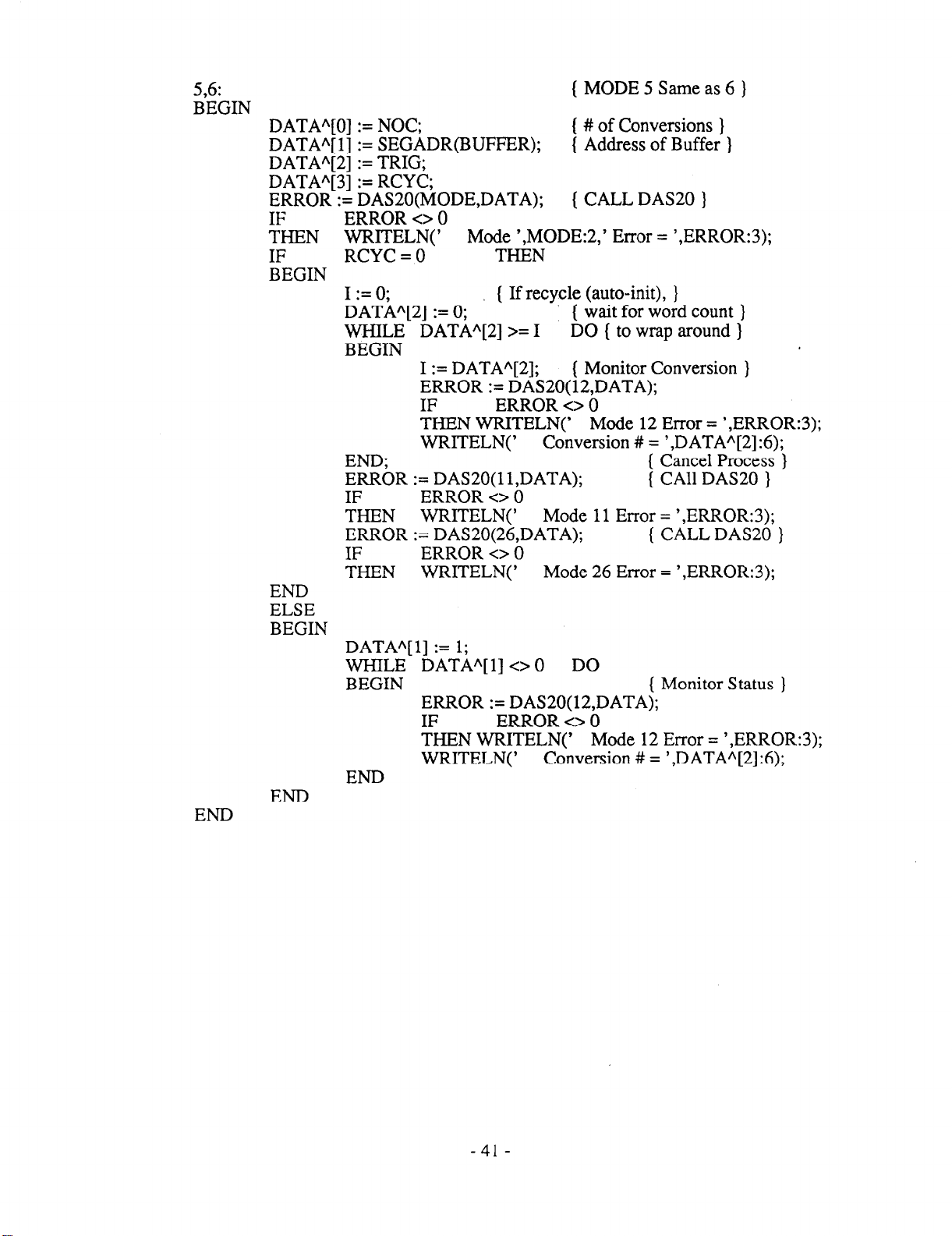
5,6:
BEGIN
END
DATA”[O] := NOC;
DATA”[ l] := SEGADR(BUFFER);
DATAA[2] := TRIG;
DATA*[3] := RCYC;
ERROR := DAS20(MODE,DATA);
IF
THEN
IF
BEGIN
END
ELSE
BEGIN
END
ERROR 0 0
WRIT.ELN( ’
RCYC = 0
I := 0;
DATA”[2] := 0;
WHILE DATA”[2] >= I DO ( to wrap around )
BEGIN
I := DATAA[2]; ( Monitor Conversion }
THEN WRITELN(’ Mode 12 Error = ‘,ERROR:3
%R := DAS20( 11 DATA);
&EN WRITELN(’ Mode 11 Error = ‘,ERROR:3);
ERROR := DAS20(26,DATA); ( CALL DAS20 }
FHEN WRrrELN(’
DATA”[l] := 1;
WHILE DATAA[l] <> 0 DO
BEGIN
END
Mode ‘,MODE:2,’ Error = ‘,ERROR:3);
THEN
( If recycle (auto-init), }
ERROR := DAS20(12,DATA);
IF ERROR <> 0
WRITELN(’ Conversion # = ‘,DATA*[2]:6);
ERROR <> b
ERROR <> 0
ERROR := DAS20(12,DATA);
IF ERROR <> 0
THEN WRITELN(’ Mode 12 Error = ‘,ERROR:3);
WRITELN(’
MODE 5 Same as 6 )
# of Conversions }
Address of Buffer )
CALL DAS20 )
( wait for word count )
3;
( Cancel Process }
{ CA11 DAS20 }
Mode 26 Error = ‘,ERROR:3);
( Monitor Status ]
Conversion # = ‘,DATAA[2]:6);
-41-
Page 46

Section 3
DAS-20 C LANGUAGE INTERFACE
The DAS-20 BASIC Interface has been converted to a Clanguage callable Library:
DAS20c.LIB. This was accomplished by removing the BASIC specific despatcher code to a
separate INCLUDE file, DAS20b.ASM and INCLUDing instead the file DAS20cASM in
DAS20.ASM. DAS2OcLIB consist of the single OBJ file DAS20.0BJ, which also contains the
routines: SEGADR, OFFADR and ALLOC.SEGADR and OFFADR return the segment and
offset values of amemory buffer. This is very useful in calls to DAS20 from C.Modes 5 and 6,
for example, require the segment value and assume the offset to be 0, modes 4, 8, 13 etc. require
the offset value and assume the segment to be the same as that of DIO%(). ALLOC(#) allocates a
buffer of # of 16-bit words and returns a far pointer to it. It guarantees paragraph alignment and
enough room for # conversions. i.e. OFFADR(ALLOC(#)) will always = 0 and
SEGADR(ALLOC(#)) + #/16 c O-FFFh. Thus ALLOC(32766) returns a segment suitable for
DMAing the maximum number of conversions in mode 6 or 27.
The CxDRAW.LIB graphics libraries have also been included on this disk [x =
S(mall),M(edium),C(ompact) or L(arge)]. It contains the non-DAS-20 Graphics routines, such as
SETUP(mode),CLEAR(i,r,g,b) COLOR(i,r,g,b),POINT(x,y) and LINE(xO,yO,xl,y2). All
parameters are 16 bit integers. Mode is the IBM BIOS crt-mode. Intensity, red, green, blue, if
non-zero, turn on those color planes when 16 colors are available for that mode. x, y, x0, y0, xl,
yl are 16 bit signed integers and represent screen coordinates in center = (0,O) format. The y
values are scaled by the aspect ratio for the given mode so that n pixels in the vertical direction
are roughly the same distance as n pixels in the horizontal direction. The graphics libraries may
eventually do more, but for now are offered as is. If you do not have an EGA display system, you
must change the value of mode in the demos to CGA mode 4,5 or 6.
To re-LINK any of the example programs, use DAS2Ocl+clDRAW at the libraries
prompt. If you recompile with MSC, be sure to specify the correct memory model with /Ax (x =
S,M,C or L). The MAKEDEMO.BAT utility is provided for this purpose (see
MAKEDEMO.DOC).
The example programs, D20MO-6.C, D20M27.C, D20M7-lO.C, D20M16.C and
D20M23.C test various modes (the numbers or range of numbers after the M). These programs
contain other commented options and can be used as a starting point to develop specialized user
programs in C. D20MO-6 gives the user an on-line way of testing and comparing the various
analog to digital conversion modes. Be sure not to exceed the maximum rate for the given mode.
D20M27 tests block scan mode. D20M7-10 tests the DAC output modes. D20M16 test the
analog trigger function and D20M23 test the frequency measurement routine.
- 42 -
Page 47
Most of the DAS-20 Manual (for BASIC) applies to the C language package. The
format of the BASIC call is:
CALL DAS20 (MD%,DIO%(O),FLAG%)
This becomes a function routine reference in C:
FLAG% = DAS2O(MD%,DIO%(O))
The FLAG% returned value (16-bit) can be ignored if zero.
The MD% value (16-bit) is the BASIC MODE (0 - 29).
DIO% is a 16-bit array which contains up to 9 other parameters,
which are either input or output from the DAS20 routines.
-43 -
Page 48

3.1 Example Program
A number of sample and example programs have been included on the PCF-20 disks, however as
a quick example a printout of one of the programs has been included. An excerpt from the
D20MO-6.C demo follows:
case 6:
/* MODE 6 */
data[O] = not;
data[ l] = segadr(buffer); /* Paragraph Address of Buffer */
data[2] = trig;
data[3] = rcyc;
if
if
t
1
else
1
) break;
((error = das20(mode,data)) != 0) /* CALL DAS20 */
printf( ‘In Mode %u Error = %d”,mode,error);
== 0)
WC
i = 0; /* Lf recycle (auto-init), */
data[2] = 0;
while (data[2] >= i) /* to wrap around */
{
1
if ((error = das20( 11,data)) != 0) /* CALL DAS20 */
if ((error = das20(26,data)) != 0) /* CALL DAS20 */
data[l] = 1;
while (data[ l] != 0)
{
1
i = data[2];
if ((error = das20(12,data)) != 0)
printf( ‘Yn
printf( “n
printf( ‘Yn
printf(‘ln Mode 26 Error = %d”,error);
if ((error = das20( 12,data)) != 0)
printf(‘ln Mode 12 Error = %d”,error);
printf( ‘Yn Conversion # = %u”,data[2]);
/* # of Conversions */
/* wait for word count */
/* Monitor Conversion */
Mode 12 Error = %d”,error);
Conversion # = %u”,data[2]);
/* Cancel Process */
Mode 11 Error = %d”,error);
/* Monitor Status */
’
- 44 -
Page 49

Section 4
DAS-20 FORTRAN INTERFACE
The DAS-20 BASIC Interface has been converted to a FORTRAN callable Library:
DAS20f.LIB. This was accomplished by removing the BASIC specific despatcher code to a
separate INCLUDE file, DAS20b.ASM and INCLUDing instead the file DAS20f.ASM in
AS20.ASM. DAS20f.LIB consist of the single OBJ file DAS20.0BJ, which also contains the
routines: SEGADR, OFFADR and ALLOC. SEGADR and OFFADR return the segment and
offset values of a memory buffer. This is very useful in calls to DAS20 from FORTRAN. Be
sure to declare each of these functions as INTEGER*2 in your program. Modes 6 and 7, for
example, require the segment value and assume the offset to be 0, mode 4, 8, 13 etc require the
offset value and assume the segment to be the same as that of DIO%(). ALLOC(#) allocates a
buffer of # of 16-bit words and returns a far pointer to it. It guarantees paragraph alignment and
enough room for # conversions. i.e. OFFADR(ALLOC(#)) will always = 0 and
SEGADR(ALLOC(#)) + #/16 < O-FFFh. Thus ALLOC(32766) returns a segment suitable for
DMAing the maximum number of conversions in mode 6 or 27,
The FDRAW.LlB graphics library has also been included on
this disk. It contains the non-DAS-20 Graphics routines, such as
SETUP(mode), CLEAR(i,r,g,b), COLOR(i,r,g,b), POINT(x,y) and
LINE(xO,yO,xl,y2). All parameters are 16 bit integers. Mode is the IBM BIOS crt-mode.
Intensity, red, green, blue, if non-zero, turn on those color planes when 16 colors are available
for that mode. x, y, x0, y0, xl, yl are 16 bit signed integers and represent screen coordinates in
center =
pixels in the vertical direction are roughly the same distance as n pixels in the horizontal
direction, The graphic library may eventually do more, but for now is offered as is. If you do not
have an EGA display system, you must change the value of mode in the demos to CGA mode 4,
5 or 6.
(0,O) format. The y values are scaled by the aspect ratio for the given mode so that n
To re-LINK any of the example programs, use DAS20F+FDRAW at the libraries
prompt. The MAKEDEMO.BAT utility is provided for this purpose (see MAKEDEMO.DOC).
The example programs,
D20M16.FOR and D20M23.FOR test various modes (the numbers or range of numbers after the
M). These programs contain other commented options and can be used as a starting point to
develop specialized user programs in FORTRAN. D20MO-6 gives the user an on-line way of
testing and comparing the various analog to digital conversion modes. Be sure not to exceed the
maximum rate for the given mode. D20M27 tests block scan mode. D20M7-10 tests the DAC
output modes. D20M16 test the analog trigger function and D20M23 test the frequency
measurement routine.
D20MOs6.FOR, D20M27.FOR, D20M7-lO.FOR
- 45 -
Page 50

Most of the DAS-20 Manual (for BASIC) applies to the FORTRAN package. The
format of the BASIC call is:
CALL DAS20 (MD%,DIO%(O),FLAG%)
This becomes a function routine reference in FORTRAN:
FLAG% = DAS20(MD%,DIO%( 1))
The FLAG% returned value (16-bit) can be ignored if zero.
The MD% value (16-bit) is the BASIC MODE (0 - 29).
DIO% is a 16-bit array which contains up to 9 other parameters,
which are either input or output from the DAS20 routines.
4.1 Example Program
A number of sample and example programs in Fortran have been included on the PCF-20’s
Fortran disk. However, as a quick example the following program listing is included. An
excerpt from the D20MO-6.FOR demo follows:
*
*
603
Mode 6 (DMA control)
PARAM(1) = NOC
PARAM(2) = SEGADR(BUFFER)
PARAM(3) = TRIG
PARAM(4) = RCYC
RCODE = DAS20(IMODE, PARAM)
IF (RCODE NE. 0) WRITE(*, 120) IMODE, RCODE
Use mode 12 to determine status of interrupt/DMA
IMODE = 12
IF (RCYC .EQ. 0) THEN
PARAM(3) = 0
CONTINUE
I = PARAM(3)
RCODE = DAS20(IMODE, PARAM)
IF (RCODE NE. 0) WRITE(*, 120) IMODE, RCODE
WRITE(*, 17 1) PARAM(3)
IF (PARAM(3) .GE. I) GOT0 603
- 46 -
Page 51

use mode 11 to shut down interrupt/DMA operation
IMODE = 11
RCODE = DAS20(IMODE, PARAM)
IF (RCODE NE. 0) WRITE(*, 120) IMODE, RCODE
use mode 26 to shut down the ADC PACER
IMODE = 26
PARAM(1) = 2
RCODE = DAS20(IMODE, PARAM)
IF (RCODE NE. 0) WRITE(*, 120) IMODE, RCODE
ELSE
PARAM(2) = 1
604
700
CONTINUE
RCODE = DAS20(IMODE, PARAM)
IF (RCODE NE. 0) WRITE(*, 120) IMODE, RCODE
WRITE(*, 171) PARAM(3)
IF (PARAM(2) NE. 0) GOT0 604
ENDIF
ENDIF
CONTINUE
- 47 -
 Loading...