

Page 1

Service Manual
TG 2000
Signal Generation Platform
070-9299-01
Warning
The servicing instructions are for use by qualified
personnel only. To avoid personal injury, do not
perform any servicing unless you are qualified to
do so. Refer to all safety summaries prior to
performing service.
Page 2

Copyright T ektronix, Inc. All rights reserved.
T ektronix products are covered by U.S. and foreign patents, issued and pending. Information in this publication supercedes
that in all previously published material. Specifications and price change privileges reserved.
Printed in the U.S.A.
T ektronix, Inc., P.O. Box 1000, Wilsonville, OR 97070–1000
TEKTRONIX and TEK are registered trademarks of T ektronix, Inc.
Windows and Microsoft are registered trademarks of the Microsoft corporation.
Page 3

WARRANTY
T ektronix warrants that the products that it manufactures and sells will be free from defects in materials and workmanship
for a period of one (1) year from the date of shipment. If a product proves defective during this warranty period, T ektronix,
at its option, either will repair the defective product without charge for parts and labor, or will provide a replacement in
exchange for the defective product.
In order to obtain service under this warranty, Customer must notify Tektronix of the defect before the expiration of the
warranty period and make suitable arrangements for the performance of service. Customer shall be responsible for
packaging and shipping the defective product to the service center designated by T ektronix, with shipping charges prepaid.
T ektronix shall pay for the return of the product to Customer if the shipment is to a location within the country in which the
T ektronix service center is located. Customer shall be responsible for paying all shipping charges, duties, taxes, and any
other charges for products returned to any other locations.
This warranty shall not apply to any defect, failure or damage caused by improper use or improper or inadequate
maintenance and care. T ektronix shall not be obligated to furnish service under this warranty a) to repair damage resulting
from attempts by personnel other than T ektronix representatives to install, repair or service the product; b) to repair
damage resulting from improper use or connection to incompatible equipment; c) to repair any damage or malfunction
caused by the use of non-T ektronix supplies; or d) to service a product that has been modified or integrated with other
products when the effect of such modification or integration increases the time or difficulty of servicing the product.
THIS WARRANTY IS GIVEN BY TEKTRONIX IN LIEU OF ANY OTHER WARRANTIES, EXPRESS OR
IMPLIED. TEKTRONIX AND ITS VENDORS DISCLAIM ANY IMPLIED WARRANTIES OF
MERCHANTABILITY OR FITNESS FOR A PARTICULAR PURPOSE. TEKTRONIX’ RESPONSIBILITY TO
REP AIR OR REPLACE DEFECTIVE PRODUCTS IS THE SOLE AND EXCLUSIVE REMEDY PROVIDED TO
THE CUSTOMER FOR BREACH OF THIS WARRANTY. TEKTRONIX AND ITS VENDORS WILL NOT BE
LIABLE FOR ANY INDIRECT , SPECIAL, INCIDENTAL, OR CONSEQUENTIAL DAMAGES IRRESPECTIVE
OF WHETHER TEKTRONIX OR THE VENDOR HAS ADVANCE NOTICE OF THE POSSIBILITY OF SUCH
DAMAGES.
Page 4

Service Assurance
If you have not already purchased Service Assurance for this product, you may do so at any time during the product’s
warranty period. Service Assurance provides Repair Protection and Calibration Services to meet your needs.
Repair Protection extends priority repair services beyond the product’s warranty period; you may purchase up to three
years of Repair Protection.
Calibration Services provide annual calibration of your product, standards compliance and required audit documentation,
recall assurance, and reminder notification of scheduled calibration. Coverage begins upon registration; you may purchase
up to five years of Calibration Services.
Service Assurance Advantages
Priced well below the cost of a single repair or calibration
Avoid delays for service by eliminating the need for separate purchase authorizations from your company
Eliminates unexpected service expenses
For Information and Ordering
For more information or to order Service Assurance, contact your T ektronix representative and provide the information
below . Service Assurance may not be available in locations outside the United States of America.
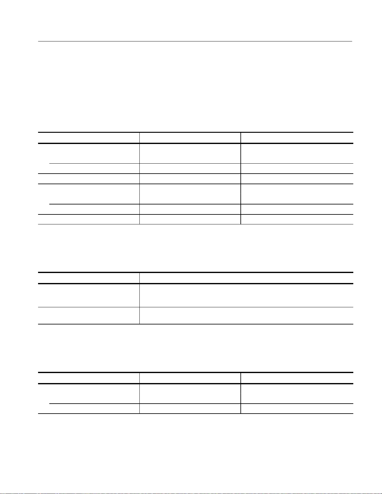
Name VISA or Master Card number and expiration
Company date or purchase order number
Address Repair Protection (1,2, or 3 years)
City , State, Postal code Calibration Services (1,2,3,4, or 5 years)
Country Instrument model and serial number
Phone Instrument purchase date
Page 5

Table of Contents
General Safety Summary vii. . . . . . . . . . . . . . . . . . . . . . . . . . . . . . . . . . . . . . . . . . .
Service Safety Summary ix. . . . . . . . . . . . . . . . . . . . . . . . . . . . . . . . . . . . . . . . . . .
Preface xi. . . . . . . . . . . . . . . . . . . . . . . . . . . . . . . . . . . . . . . . . . . . . . . . . . . . . . . . .
Specifications
Specifications 1–1. . . . . . . . . . . . . . . . . . . . . . . . . . . . . . . . . . . . . . . . . . . . . . . . . . . .
Product Description 1–1. . . . . . . . . . . . . . . . . . . . . . . . . . . . . . . . . . . . . . . . . . . . . . .
Accessories 1–2. . . . . . . . . . . . . . . . . . . . . . . . . . . . . . . . . . . . . . . . . . . . . . . . . . . . . .
Characteristics T ables 1–3. . . . . . . . . . . . . . . . . . . . . . . . . . . . . . . . . . . . . . . . . . . . . .
Operating Information
Installation 2–1. . . . . . . . . . . . . . . . . . . . . . . . . . . . . . . . . . . . . . . . . . . . . . . . . . . . . .
Operating Information 2–6. . . . . . . . . . . . . . . . . . . . . . . . . . . . . . . . . . . . . . . . . . . . .
Theory of Operation
Block Level Description 3–1. . . . . . . . . . . . . . . . . . . . . . . . . . . . . . . . . . . . . . . . . . .
Performance Verification
Verification Interval 4–1. . . . . . . . . . . . . . . . . . . . . . . . . . . . . . . . . . . . . . . . . . . . . . .
T est Equipment Required 4–1. . . . . . . . . . . . . . . . . . . . . . . . . . . . . . . . . . . . . . . . . . .
Preparation 4–2. . . . . . . . . . . . . . . . . . . . . . . . . . . . . . . . . . . . . . . . . . . . . . . . . . . . . .
Verification Procedures 4–2. . . . . . . . . . . . . . . . . . . . . . . . . . . . . . . . . . . . . . . . . . . .
Adjustment Procedures
Equipment Required 5–1. . . . . . . . . . . . . . . . . . . . . . . . . . . . . . . . . . . . . . . . . . . . . . .
Preparation 5–2. . . . . . . . . . . . . . . . . . . . . . . . . . . . . . . . . . . . . . . . . . . . . . . . . . . . . .
Self Calibration 5–2. . . . . . . . . . . . . . . . . . . . . . . . . . . . . . . . . . . . . . . . . . . . . . . . . .
Adjustment Procedure 5–3. . . . . . . . . . . . . . . . . . . . . . . . . . . . . . . . . . . . . . . . . . . . .
Maintenance
Preparation 6–1. . . . . . . . . . . . . . . . . . . . . . . . . . . . . . . . . . . . . . . . . . . . . . . . . . . . . .
Inspection and Cleaning 6–3. . . . . . . . . . . . . . . . . . . . . . . . . . . . . . . . . . . . . . . . . . . .
After Repair Adjustments 6–4. . . . . . . . . . . . . . . . . . . . . . . . . . . . . . . . . . . . . . . . . .
Repackaging Instructions 6–4. . . . . . . . . . . . . . . . . . . . . . . . . . . . . . . . . . . . . . . . . . .
Removal and Replacement 6–9. . . . . . . . . . . . . . . . . . . . . . . . . . . . . . . . . . .
T ools Required 6–9. . . . . . . . . . . . . . . . . . . . . . . . . . . . . . . . . . . . . . . . . . . . . . . . . . .
Procedures 6–10. . . . . . . . . . . . . . . . . . . . . . . . . . . . . . . . . . . . . . . . . . . . . . . . . . . . . .
Troubleshooting Procedures 6–37. . . . . . . . . . . . . . . . . . . . . . . . . . . . . . . . . .
Equipment Required 6–37. . . . . . . . . . . . . . . . . . . . . . . . . . . . . . . . . . . . . . . . . . . . . . .
General Troubleshooting Procedures 6–37. . . . . . . . . . . . . . . . . . . . . . . . . . . . . . . . . .
Fault Symptom T able 6–40. . . . . . . . . . . . . . . . . . . . . . . . . . . . . . . . . . . . . . . . . . . . . .
Troubleshooting Flowcharts 6–41. . . . . . . . . . . . . . . . . . . . . . . . . . . . . . . . . . . . . . . . .
TG 2000 Signal Generation Platform Service Manual
i
Page 6

Contents
Options
Options 7–1. . . . . . . . . . . . . . . . . . . . . . . . . . . . . . . . . . . . . . . . . . . . . . . . . . .
Replaceable Electrical Parts
Replaceable Electrical Parts 8–1. . . . . . . . . . . . . . . . . . . . . . . . . . . . . . . . . .
Diagrams
Diagrams 9–1. . . . . . . . . . . . . . . . . . . . . . . . . . . . . . . . . . . . . . . . . . . . . . . . .
Mainframe Interconnect Diagrams 9–1. . . . . . . . . . . . . . . . . . . . . . . . . . . . . . . . . . .
Modules Interconnect Diagrams 9–1. . . . . . . . . . . . . . . . . . . . . . . . . . . . . . . . . . . . .
Replaceable Mechanical Parts
Replaceable Parts 10–1. . . . . . . . . . . . . . . . . . . . . . . . . . . . . . . . . . . . . . . . . .
Parts Ordering Information 10–1. . . . . . . . . . . . . . . . . . . . . . . . . . . . . . . . . . . . . . . . .
Using the Replaceable Parts List 10–2. . . . . . . . . . . . . . . . . . . . . . . . . . . . . . . . . . . . .
Index
ii
TG 2000 Signal Generation Platform Service Manual
Page 7

List of Figures
Contents
Figure 2–1: Location of the rear-panel power connector
and configuration 2–2. . . . . . . . . . . . . . . . . . . . . . . . . . . . . . . . . . . . . . .
Figure 2–2: Location of the CPU configuration switch 2–3. . . . . . . . . . . .
Figure 2–3: Installing the rackmount hardware 2–4. . . . . . . . . . . . . . . . .
Figure 2–4: Installing the TG 2000 Platform mainframe
into the rack 2–5. . . . . . . . . . . . . . . . . . . . . . . . . . . . . . . . . . . . . . . . . . . .
Figure 2–5: Instrument front panel 2–7. . . . . . . . . . . . . . . . . . . . . . . . . . . .
Figure 2–6: Browsed and selected display icons 2–9. . . . . . . . . . . . . . . . . .
Figure 2–7: Main display features 2–11. . . . . . . . . . . . . . . . . . . . . . . . . . . . .
Figure 2–8: Module and test signal hierarchy 2–12. . . . . . . . . . . . . . . . . . .
Figure 2–9: Selecting the Save Signals to Disk source 2–14. . . . . . . . . . . . .
Figure 2–10: Selecting a Save Signals to Disk destination 2–15. . . . . . . . . .
Figure 2–11: Replacing test signals from disk 2–16. . . . . . . . . . . . . . . . . . .
Figure 2–12: Selecting the source signals to add from disk 2–17. . . . . . . . .
Figure 2–13: Add Signals window with source and destination
selected 2–18. . . . . . . . . . . . . . . . . . . . . . . . . . . . . . . . . . . . . . . . . . . . . . . .
Figure 2–14: Rear-panel connectors 2–19. . . . . . . . . . . . . . . . . . . . . . . . . . .
Figure 2–15: RS–232 connector pin descriptions 2–20. . . . . . . . . . . . . . . . .
Figure 3–1: Simplified block diagram 3–1. . . . . . . . . . . . . . . . . . . . . . . . . .
Figure 3–2: Block diagram of the clocks and frame reset signals 3–4. . . .
Figure 3–3: Comparison of module delay and system delay from
a reference 3–5. . . . . . . . . . . . . . . . . . . . . . . . . . . . . . . . . . . . . . . . . . . . .
Figure 3–4: Block diagram of module timing delay 3–6. . . . . . . . . . . . . . .
Figure 3–5: Block diagram of the AGL1 Reference timing delay 3–6. . .
Figure 4–1: Save Signals to Disk window 4–3. . . . . . . . . . . . . . . . . . . . . . .
Figure 4–2: New Directory window 4–4. . . . . . . . . . . . . . . . . . . . . . . . . . . .
Figure 4–3: New directory named Test 4–4. . . . . . . . . . . . . . . . . . . . . . . . .
Figure 4–4: Equipment setup for verifying clock operation 4–9. . . . . . . .
Figure 5–1: Measuring the power supply voltages on the clock board 5–4
Figure 5–2: Locating parts on the clock board 5–5. . . . . . . . . . . . . . . . . . .
Figure 6–1: Placing the module in the protective wrapping 6–5. . . . . . . .
Figure 6–2: Placing the module in the shipping carton 6–6. . . . . . . . . . . .
TG 2000 Signal Generation Platform Service Manual
iii
Page 8

Contents
Figure 6–3: Placing the TG 2000 Platform mainframe in the
shipping carton 6–7. . . . . . . . . . . . . . . . . . . . . . . . . . . . . . . . . . . . . . . . .
Figure 6–4: Top cover removal 6–11. . . . . . . . . . . . . . . . . . . . . . . . . . . . . . . .
Figure 6–5: Removing the front-frame assembly 6–12. . . . . . . . . . . . . . . . .
Figure 6–6: Removing the front-panel board and display
module 6–13. . . . . . . . . . . . . . . . . . . . . . . . . . . . . . . . . . . . . . . . . . . . . . . .
Figure 6–7: Disconnecting the LCD Display module and Front
Panel board 6–14. . . . . . . . . . . . . . . . . . . . . . . . . . . . . . . . . . . . . . . . . . . .
Figure 6–8: Replacing the knob encoder 6–15. . . . . . . . . . . . . . . . . . . . . . . .
Figure 6–9: Replacing the airflow regulator 6–16. . . . . . . . . . . . . . . . . . . . .
Figure 6–10: Removing the floppy drive 6–17. . . . . . . . . . . . . . . . . . . . . . . .
Figure 6–11: Installing the floppy drive into the chassis 6–19. . . . . . . . . . .
Figure 6–12: Removing the floppy drive assembly shield 6–20. . . . . . . . . .
Figure 6–13: Location of the Power Supply module grounding strap
(SN B010391 and below only) 6–21. . . . . . . . . . . . . . . . . . . . . . . . . . . . .
Figure 6–14: Removing the Power Supply module 6–22. . . . . . . . . . . . . . .
Figure 6–15: Removing the Power Supply module attaching
screws 6–22. . . . . . . . . . . . . . . . . . . . . . . . . . . . . . . . . . . . . . . . . . . . . . . . .
Figure 6–16: Removing the Power Supply board 6–24. . . . . . . . . . . . . . . . .
Figure 6–17: Removing the Line Filter board 6–25. . . . . . . . . . . . . . . . . . .
Figure 6–18: Installing the fuse holder 6–27. . . . . . . . . . . . . . . . . . . . . . . . .
Figure 6–19: Removing the CPU module floppy cable 6–28. . . . . . . . . . . .
Figure 6–20: Installing the CPU Memory board 6–29. . . . . . . . . . . . . . . . .
Figure 6–21: Removing the date/time clock from the CPU module 6–30. .
Figure 6–22: Installing the Clock board oscillator 6–32. . . . . . . . . . . . . . . .
Figure 6–23: Removing the Power Supply board fan 6–33. . . . . . . . . . . . .
Figure 6–24: Removing the Clock board fan 6–34. . . . . . . . . . . . . . . . . . . .
Figure 6–25: Removing the Backplane board 6–35. . . . . . . . . . . . . . . . . . .
Figure 6–26: Replacing the battery 6–36. . . . . . . . . . . . . . . . . . . . . . . . . . . .
Figure 6–27: Instrument does not boot up properly 6–41. . . . . . . . . . . . . .
Figure 6–28: Measuring the power supply voltages on the
clock board 6–42. . . . . . . . . . . . . . . . . . . . . . . . . . . . . . . . . . . . . . . . . . . .
Figure 6–29: Backlight does not illuminate 6–42. . . . . . . . . . . . . . . . . . . . .
Figure 6–30: Measuring the LCD Display module high voltage 6–43. . . . .
Figure 6–31: Front panel does not function 6–43. . . . . . . . . . . . . . . . . . . . .
Figure 6–32: Locked LED does not illuminate 6–44. . . . . . . . . . . . . . . . . . .
Figure 6–33: Floppy drive does not operate properly 6–44. . . . . . . . . . . . .
Figure 6–34: Instrument is hot or the fans do not operate 6–45. . . . . . . . .
Figure 6–35: Correct time is not stored 6–46. . . . . . . . . . . . . . . . . . . . . . . . .
Figure 6–36: Signal noise in mainframe slots 9 and 10 6–46. . . . . . . . . . . .
iv
TG 2000 Signal Generation Platform Service Manual
Page 9

Figure 6–37: Instrument loses signal and operating memory during
rear-panel power off 6–47. . . . . . . . . . . . . . . . . . . . . . . . . . . . . . . . . . . . .
Figure 6–38: Measuring the battery charging circuit 6–48. . . . . . . . . . . . .
Figure 6–39: Front-panel knob does not function properly 6–48. . . . . . . .
Figure 9–1: Backplane board connections 9–2. . . . . . . . . . . . . . . . . . . . . .
Figure 9–2: CPU, Front Panel board, Power Supply board and
Line Filter connections 9–3. . . . . . . . . . . . . . . . . . . . . . . . . . . . . . . . . .
Figure 9–3: Clock connections 9–4. . . . . . . . . . . . . . . . . . . . . . . . . . . . . . . .
Figure 9–4: AGL1 module connections 9–4. . . . . . . . . . . . . . . . . . . . . . . . .
Figure 9–5: AVG1 module connections 9–5. . . . . . . . . . . . . . . . . . . . . . . . .
Figure 9–6: AWVG1 module connections 9–5. . . . . . . . . . . . . . . . . . . . . . .
Figure 9–7: BG1 module connections 9–6. . . . . . . . . . . . . . . . . . . . . . . . . .
Figure 9–8: GP1 module connections 9–6. . . . . . . . . . . . . . . . . . . . . . . . . .
Figure 9–9: DVG1 module connections (standard) 9–7. . . . . . . . . . . . . . .
Figure 9–10: DVG1 module connections (with Option S1 installed as
shipped) 9–7. . . . . . . . . . . . . . . . . . . . . . . . . . . . . . . . . . . . . . . . . . . . . . .
Contents
Figure 10–1: Top cover and chassis assembly 10–6. . . . . . . . . . . . . . . . . . . .
Figure 10–2: Front panel, disk drive and display 10–8. . . . . . . . . . . . . . . . .
Figure 10–3: Disk drive assembly 10–10. . . . . . . . . . . . . . . . . . . . . . . . . . . . .
Figure 10–4: Power Supply module assembly 10–12. . . . . . . . . . . . . . . . . . .
Figure 10–5: CPU assembly 10–14. . . . . . . . . . . . . . . . . . . . . . . . . . . . . . . . . .
Figure 10–6: Clock assembly 10–16. . . . . . . . . . . . . . . . . . . . . . . . . . . . . . . . .
Figure 10–7: Accessories 10–18. . . . . . . . . . . . . . . . . . . . . . . . . . . . . . . . . . . . .
TG 2000 Signal Generation Platform Service Manual
v
Page 10

Contents
List of Tables
Table 1–1: AC Power source 1–3. . . . . . . . . . . . . . . . . . . . . . . . . . . . . . . . .
Table 1–2: Physical dimensions 1–3. . . . . . . . . . . . . . . . . . . . . . . . . . . . . . .
Table 1–3: Environmental characteristics 1–3. . . . . . . . . . . . . . . . . . . . . .
Table 1–4: System clock and frame reset 1–5. . . . . . . . . . . . . . . . . . . . . . .
Table 1–5: Certifications and compliances 1–6. . . . . . . . . . . . . . . . . . . . . .
Table 2–1: AC power fuse requirements 2–2. . . . . . . . . . . . . . . . . . . . . . .
Table 2–2: Keypad definitions 2–8. . . . . . . . . . . . . . . . . . . . . . . . . . . . . . . .
Table 4–1: Test equipment required for verification 4–1. . . . . . . . . . . . . .
Table 5–1: Equipment List for adjustments 5–1. . . . . . . . . . . . . . . . . . . .
Table 6–1: Tools required for module removal 6–9. . . . . . . . . . . . . . . . . .
Table 6–2: Removal and replacement procedure list 6–10. . . . . . . . . . . . .
Table 6–3: Equipment required for troubleshooting 6–37. . . . . . . . . . . . .
Table 6–4: CPU confidence test codes 6–40. . . . . . . . . . . . . . . . . . . . . . . . .
Table 6–5: Fault symptom table 6–40. . . . . . . . . . . . . . . . . . . . . . . . . . . . . .
Table 7–1: Power cord identification 7–1. . . . . . . . . . . . . . . . . . . . . . . . . .
vi
TG 2000 Signal Generation Platform Service Manual
Page 11

General Safety Summary
Review the following safety precautions to avoid injury and prevent damage to
this product or any products connected to it.
Only qualified personnel should perform service procedures.
To avoid potential hazards, use this product only as specified.
Injury Precautions
Product Damage
Precautions
Use Proper Power Cord. To avoid fire hazard, use only the power cord specified
for this product.
Avoid Electric Overload. To avoid electric shock or fire hazard, do not apply a
voltage to a terminal that is outside the range specified for that terminal.
Ground the Product. This product is grounded through the grounding conductor
of the power cord. To avoid electric shock, the grounding conductor must be
connected to earth ground. Before making connections to the input or output
terminals of the product, ensure that the product is properly grounded.
Do Not Operate Without Covers. To avoid electric shock or fire hazard, do not
operate this product with covers or panels removed.
Use Proper Fuse. To avoid fire hazard, use only the fuse type and rating specified
for this product.
Do Not Operate in Wet/Damp Conditions. To avoid electric shock, do not operate
this product in wet or damp conditions.
Do Not Operate in an Explosive Atmosphere. To avoid injury or fire hazard, do not
operate this product in an explosive atmosphere.
Use Proper Power Source. Do not operate this product from a power source that
applies more than the voltage specified.
Use Proper V oltage Setting. Before applying power, ensure that the line selector is
in the proper position for the power source being used.
Provide Proper Ventilation. To prevent product overheating, provide proper
ventilation.
Do Not Operate With Suspected Failures. If you suspect there is damage to this
product, have it inspected by qualified service personnel.
TG 2000 Signal Generation Platform Service Manual
vii
Page 12

General Safety Summary
Symbols and Terms
T erms in this Manual. These terms may appear in this manual:
WARNING. Warning statements identify conditions or practices that could result
in injury or loss of life.
CAUTION. Caution statements identify conditions or practices that could result in
damage to this product or other property.
T erms on the Product. These terms may appear on the product:
DANGER indicates an injury hazard immediately accessible as you read the
marking.
WARNING indicates an injury hazard not immediately accessible as you read the
marking.
CAUTION indicates a hazard to property including the product.
Symbols on the Product. The following symbols may appear on the product:
Certifications and
Compliances
DANGER
High Voltage
Protective Ground
(Earth) T erminal
ATTENTION
Refer to Manual
Double
Insulated
Refer to the specifications section for a listing of certifications and compliances
that apply to this product.
viii
TG 2000 Signal Generation Platform Service Manual
Page 13

Service Safety Summary
Only qualified personnel should perform service procedures. Read this Service
Safety Summary and the General Safety Summary before performing any service
procedures.
Do Not Service Alone. Do not perform internal service or adjustments of this
product unless another person capable of rendering first aid and resuscitation is
present.
Disconnect Power. To avoid electric shock, disconnect the mains power by means
of the power cord or the rear-panel power switch.
Use Care When Servicing With Power On. Dangerous voltages or currents may
exist in this product. Disconnect power cord and test leads before removing
protective panels, soldering, or replacing components.
To avoid electric shock, do not touch exposed connections.
TG 2000 Signal Generation Platform Service Manual
ix
Page 14

Service Safety Summary
x
TG 2000 Signal Generation Platform Service Manual
Page 15

Preface
About This Manual
You have purchased this optional service manual for the TG 2000 Platform
mainframe. You can also purchase service manuals for the modules. Each
module manual begins with a tab so that you can locate it after you add it to the
mainframe manual binder.
The user manuals are set up the same way as the service manuals. You should
receive a user manual with each mainframe or module ordered.
This manual contains information for servicing the TG 2000 Signal Generation
Platform to a module level. The information is designed only for qualified
service technicians, with moderate experience in analog circuits, digital circuits,
and television technology. This manual is composed of the following sections:
Specifications provides a basic product description followed by instrument
specifications tables.
Operating Information is designed to provide just enough operating
information for a service technician to be able to service the product. For
more details, refer to the user manual.
Theory of Operation is an overview of the main components of the platform,
describing general interactions with the modules.
Performance Verification contains procedures necessary to verify that the
mainframe components (Clock, Power Supply, and CPU) are meeting the
requirements listed in the Specifications.
Adjustments contains procedures to adjust the +5V power supply and the
oscillator.
Maintenance contains installation, removal and replacement, and trouble-
shooting instructions.
Options lists all available options for the mainframe.
Replaceable Electrical Parts for the module level are included in the
Replaceable Mechanical Parts list.
Diagrams contains interconnect diagrams showing the connections between
the mainframe and the modules.
Replaceable Mechanical Parts lists the part numbers for replacement parts
that you can order. Exploded view illustrations help you to identify the parts.
TG 2000 Signal Generation Platform Service Manual
xi
Page 16

Preface
Contacting Tektronix
Product
Support
Service
Support
For other
information
To write us Tektronix, Inc.
For application-oriented questions about a Tektronix measurement product, call toll free in North America:
1-800-TEK-WIDE (1-800-835-9433 ext. 2400)
6:00 a.m. – 5:00 p.m. Pacific time
Or contact us by e-mail:
tm_app_supp@tek.com
For product support outside of North America, contact your
local Tektronix distributor or sales office.
Contact your local Tektronix distributor or sales office. Or visit
our web site for a listing of worldwide service locations.
http://www.tek.com
In North America:
1-800-TEK-WIDE (1-800-835-9433)
An operator will direct your call.
P.O. Box 1000
Wilsonville, OR 97070-1000
xii
TG 2000 Signal Generation Platform Service Manual
Page 17

Page 18

Specifications
Product Description
This section contains the Product Description, which describes the product and
accessories, and the Characteristics Tables, which list the product specifications.
The TG 2000 Signal Generation Platform provides multiformat, precision
television test signals for both analog and digital video standards. The physical
configuration is a mainframe with up to nine plug-in modules. Modules either
generate signals or provide special functions, such as genlock capability.
You can use included software (SDP2000 Signal Development Program) to
generate custom test signals, which you can store on a disk or transfer directly
into the memory of a generator module.
The TG 2000 Signal Generation Platform addresses the needs of research and
development, engineering, manufacturing test, and most operational environments.
These are some of the key features of the platform:
Modular architecture with up to nine generators or special function modules
Support of analog and digital environments for most component and
composite video signal formats
Reference generator performance level
Modules genlocked to external reference with the optional AGL1 Genlock
module
Included Microsoft Windows-based SDP2000 software to create new signals
Remote control, using RS-232 interface (or optional GPIB interface) and
SCPI command set
Full support of VM700A video measurement routines
Variable transmission parameters, such as jitter amplitude and frequency, for
serial digital formats using the DVG1 module with option S1
Variable signal parameters for some analog and digital format modules
Circle and text overlays on test signals for some modules
Simultaneous 525/60 and 625/50 signal generation
TG 2000 Signal Generation Platform Service Manual
1–1
Page 19

Specifications
Accessories
Moving signals for compression system testing
Programmable system clocks to support standard and custom formats
Flash EPROM allows easy upgrades to system software
This section describes the key accessories for the TG 2000 Signal Generation
Platform. For a complete list of accessories and their Tektronix part numbers,
refer to the Replaceable Mechanical Parts list at the back of this manual.
BG1 Black Burst
Generator Module
SDP2000 Signal
Development Program
GPIB Card for SDP2000
Communications
The BG1 Generator module is supplied as a standard accessory. There are six
black burst signals to select from; the module provides the selected black burst
signal on the three rear-panel connectors. Additionally, the module can provide
one of the system clocks from its rear-panel clock output.
More than one BG1 Generator module can be added to the mainframe to provide
enough flexibility to meet virtually any system timing requirement. The BG1
Generator module can be removed without affecting system operation.
The SDP2000 Signal Development Program is supplied as a standard accessory.
This program runs under Microsoft
parallel port are compatible with Windows NT. All features are compatible with
Windows 95.
You can use the SDP2000 program to create custom signals for the various
modules. You can use the remote interface or a disk to download the signals to
the module memory. Refer to the SDP2000 Signal Development Program User
Manual for information about using this program.
The Tektronix S3FG210 is a GPIB–PCII/IIA interface card. It provides the type
of interface needed to operate the TG 2000 Signal Generation Platform when
performing GPIB communications with the SDP2000/TGCOMM software.
Windows 3.1 or higher. All features except the
1–2
Accessory Kit
Extender Board
The accessory kit includes a Torx T-10 bit (needed to secure the modules), two
fuses, and a blank panel. The fuses support the two line voltage settings; see
Electrical Installation on page 2–1 for instructions. The blank panel fills the gap
when a module is removed.
The extender board is an optional accessory that you can order to use when
troubleshooting the TG 2000 Signal Generation Platform. The part number can
be found at the end of the Replaceable Mechanical Parts list.
TG 2000 Signal Generation Platform Service Manual
Page 20
Characteristics Tables
Specifications
This section lists the electrical and environmental specifications for the TG 2000
Platform mainframe. For the specifications of a specific module, refer to the user
or service manual for that module.
T able 1–1: AC Power source
Characteristic Performance requirement Reference information
AC Source Voltage
115 V operation 87 V
230 V operation 174 V
RMS
RMS
to 132 V
to 250 V
RMS
RMS
Power Consumption 220 W line power typical
Fuse Rating
115V Operation Slow blow, 6 AT
230 V Operation Slow blow, 3 AT
Nominal Switching Frequency 100 kHz
T able 1–2: Physical dimensions
Characteristic Description
Dimensions Height: 5.25 in (13.34 cm)
Width: 19.0 in (48.26 cm); standard rack width
Depth: 23 in (58.42 cm)
1
Weight
Net Weight: 38 lbs (17.27 kg) typical
Shipping Weight: 52 lbs (23.67 kg) typical
T able 1–3: Environmental characteristics
Characteristic Performance requirement Reference information
T emperature
Operating 32_ F to 104_ F (0_ C to 40_ C)
Nonoperating –4 to +140_ F (–20 to +60_ C)
1
Weight of the TG 2000 will vary depending on the number and type of generator or other modules installed.
2
Battery storage life is specified at 25_ C. At 60_ C, battery discharge accelerates, resulting in self discharge in less than
2
30 days.
TG 2000 Signal Generation Platform Service Manual
1–3
Page 21

Specifications
T able 1–3: Environmental characteristics (cont.)
Characteristic Reference informationPerformance requirement
Altitude
Operating To 15,000 feet (4572 meters)
Nonoperating To 40,000 feet (12,203 meters)
Humidity
Operating ≤ 104_ F (≤ 40_ C ), up to 95% relative
humidity
Nonoperating Up to 95% relative humidity
Heat Dissipation 220 W atts maximum for mainframe with
modules in all slots
Clearance for Cooling For rack installation, allow standard side
cooling and 2 in (5 cm) rear clearance for
cables
For desktop use, allow 2 in (5 cm) side and
rear clearance
Bench Handling 1 drop of 2 inches of each edge for all
significant surfaces
Vibration
Operating 5-100 HZ g2/Hz APSD: 0.00015
100-200 Hz Slope dB/Octave: 0
200-350 HZ g2/Hz APSD: 0.00015
350-500 Hz Slope dB/Octave: –3
500 HZ g2/Hz APSD: 0.000105
GRMS overall: 0.27[0.24]
Time/Axis minutes: 10
Nonoperating 5-100 HZ g2/Hz APSD: 0.0175
100-200 Hz Slope dB/Octave: –3
200-350 HZ g2/Hz APSD: 0.00875
350-500 Hz Slope dB/Octave: –3
500 HZ g2/Hz APSD: 0.006132
GRMS overall: 2.22
Time/Axis minutes: 10
Mechanical Shock, Nonoperating 30 g 1/2 sine, 11 ms duration 3 shocks
per surface (18 total)
1–4
TG 2000 Signal Generation Platform Service Manual
Page 22

Specifications
T able 1–3: Environmental characteristics (cont.)
Characteristic Reference informationPerformance requirement
Transportation Package qualified per Tektronix standard
062–2858–00 Rev. B “Environmental T est
Methods–Dynamics” and MBD Quality
Document ENVL–0060 “Transportation
Package Qualification Test Plan”.
Equipment Type Test and Measuring
Equipment Class Class 5
T able 1–4: System clock and frame reset
Characteristic Performance requirement Reference information
Clock Frequency 27 MHz
DDS Ch 1: 10 MHz to 100 MHz
DDS Ch 2: 10 MHz to 100 MHz
Step Size: 0.1 Hz
Stability ±1 ppm/year, operating at standard oven
temperature
Clock Jitter ≤30 ps RMS
Non-harmonic Clock Spurs –45 dBc or better
Tune Range ± 10 ppm
Frame Reset Two reset channels, 1.7 Hz to 1 kHz
TG 2000 Signal Generation Platform Service Manual
1–5
Page 23

Specifications
eclaration o
ormit
T able 1–5: Certifications and compliances
Category Standard
EC D
Safety
U.S. Nationally Recognized Laboratory
Canadian Certification CAN/CSA C22.2 No. 1010.1 Safety Requirements for Electrical Equipment for
European Union Low Voltage Directive 73/23/EEC, Amended by 93/68/EEC
Additional Compliance UL3111-1 Standard for Electrical Measuring and Test Equipment
Listing
f Conf
y Compliance was demonstrated to the following specifications as listed in the Official
Journal of the European Communities:
EN 50081-1 Emissions:
EN 55022 Class B Radiated and Conducted Emissions
EN 60555-2 AC Power Line Harmonic Emissions
EN 50082-1 Immunity:
IEC 801-2 Electrostatic Discharge Immunity
IEC 801-3 RF Electromagnetic Field Immunity
IEC 801-4 Electrical Fast T ransient/Burst Immunity
IEC 801-5 Power Line Surge Immunity
Low Voltage Directive 73/23/EEC, Amended by 93/68/EEC
EN61010-1 Safety Requirements s for Electrical Equipment for Measurement,
Control, and Laboratory Use
ANSI/ISA S82.01 Safety Standard for Electrical and Electronics Test, Measuring,
Controlling, and Related Equipment, 1994
Measurement, Control, and Laboratory Use
EN61010-1 Safety Requirements for Electrical Equipment for Measurement,
Control, and Laboratory Use
Safety Certification Compliance
T emperature, operating 41_ F to 104_ F (+5 to +40_ C)
Altitude (max operating) 6562 feet (2000 meters)
Equipment Type Test and Measuring
Safety Class Class I (as defined in IEC 1010–1, Annex H) – grounded product
Overvoltage Category Installation Category II (as defined in IEC 1010–1, Annex J).
Pollution Degree Pollution Degree 2 (as defined in IEC 1010–1). Rated for indoor use only.
1–6
IEC1010-1 Safety Requirements for Electrical for Measurement, Control, and
Laboratory Use
TG 2000 Signal Generation Platform Service Manual
Page 24

Page 25

Operating Information
This section contains the following information:
Installation instructions
Operating information
All modules that you order are shipped configured and installed in the TG 2000
Platform mainframe. Refer to Options on page 7–1 for information about any
installed options. To install or remove a module, refer to the user or service
manual for that specific module.
Installation
Before you install the TG 2000 Platform mainframe, observe these environmental considerations:
Provide the appropriate operating environment. Refer to Specifications for
temperature, humidity, altitude, and other environmental requirements.
Leave enough space for instrument cooling by ensuring standard side
clearance for rackmount installation or 2 inches (5.1 cm) of side clearance
for countertop use.
Electrical Installation
Ensure rear clearance of approximately 2 inches (5.1 cm) so that cables are
not damaged by sharp bends.
To install the TG 2000 Platform mainframe, perform these steps:
WARNING. To avoid electrical shock, be sure that the power cord is disconnected
before checking the fuse or changing the setting of the Line Selector switch.
To avoid damaging the TG 2000 Platform mainframe, always use the correct
fuse for the local line voltage. Refer to Table 2–1 on page 2–2 or the fuse chart
located on the rear panel for the proper fuse rating for each line voltage setting.
1. Using the information in Figure 2–1, set the rear-panel Line Selector switch
to the correct position for your local AC power system.
2. Check that the correct line-voltage fuse for your local AC power system is
installed. Refer to Table 2–1 for the fuse ratings.
TG 2000 Signal Generation Platform Service Manual
2–1
Page 26
Operating Information
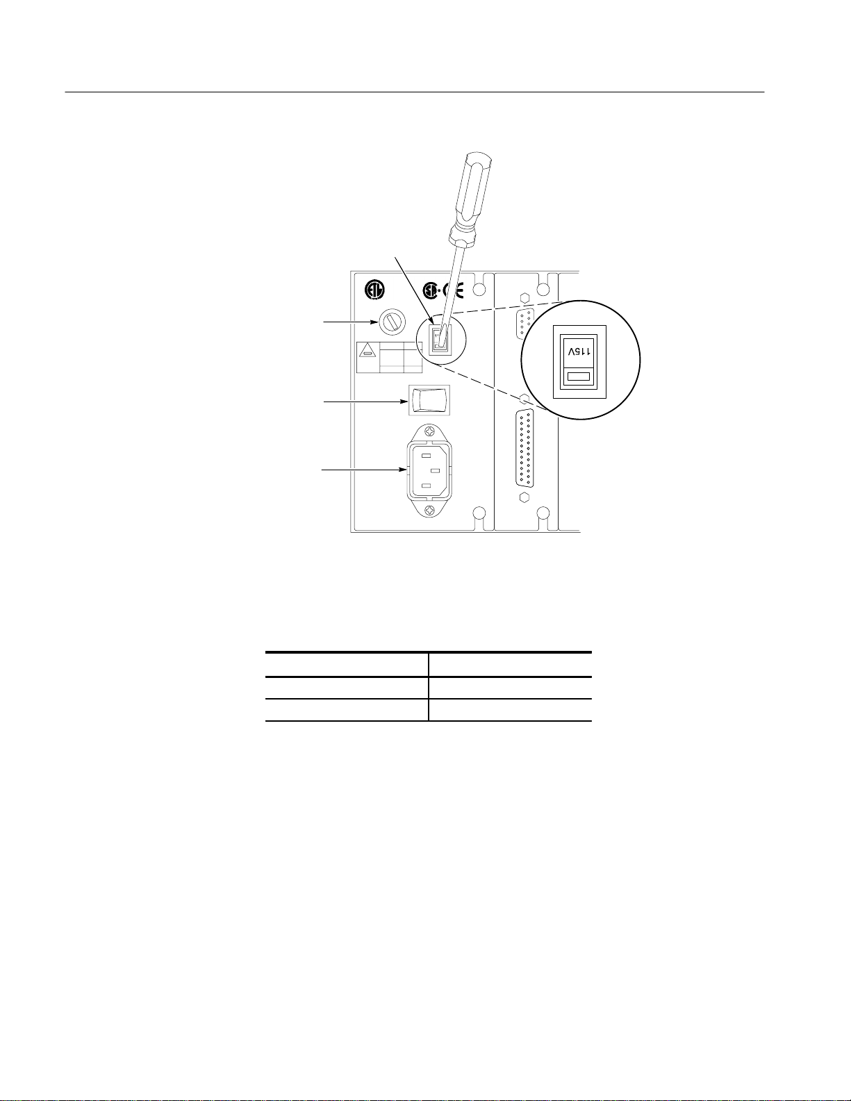
Line
selector
Fuse
Power
switch
AC line
connecter
Figure 2–1: Location of the rear-panel power connector and configuration
T able 2–1: AC power fuse requirements
Line V oltage Setting Fuse Rating
115 V 250 V, 6 AT
230 V 250 V, 3 AT
3. Check that the CPU configuration switch is in the “0” position. See
Figure 2–2.
4. Check that you are using the correct power cord for the local AC power
system. Refer to Options on page 7–1 for a list of power cords.
5. Connect the power cord from the rear-panel power connector to the AC
power system.
2–2
TG 2000 Signal Generation Platform Service Manual
Page 27

Top view of
instrument
Operating Information
Rackmount Installation
Figure 2–2: Location of the CPU configuration switch (switch set to 0)
To rackmount the TG 2000 Platform mainframe, perform the following steps:
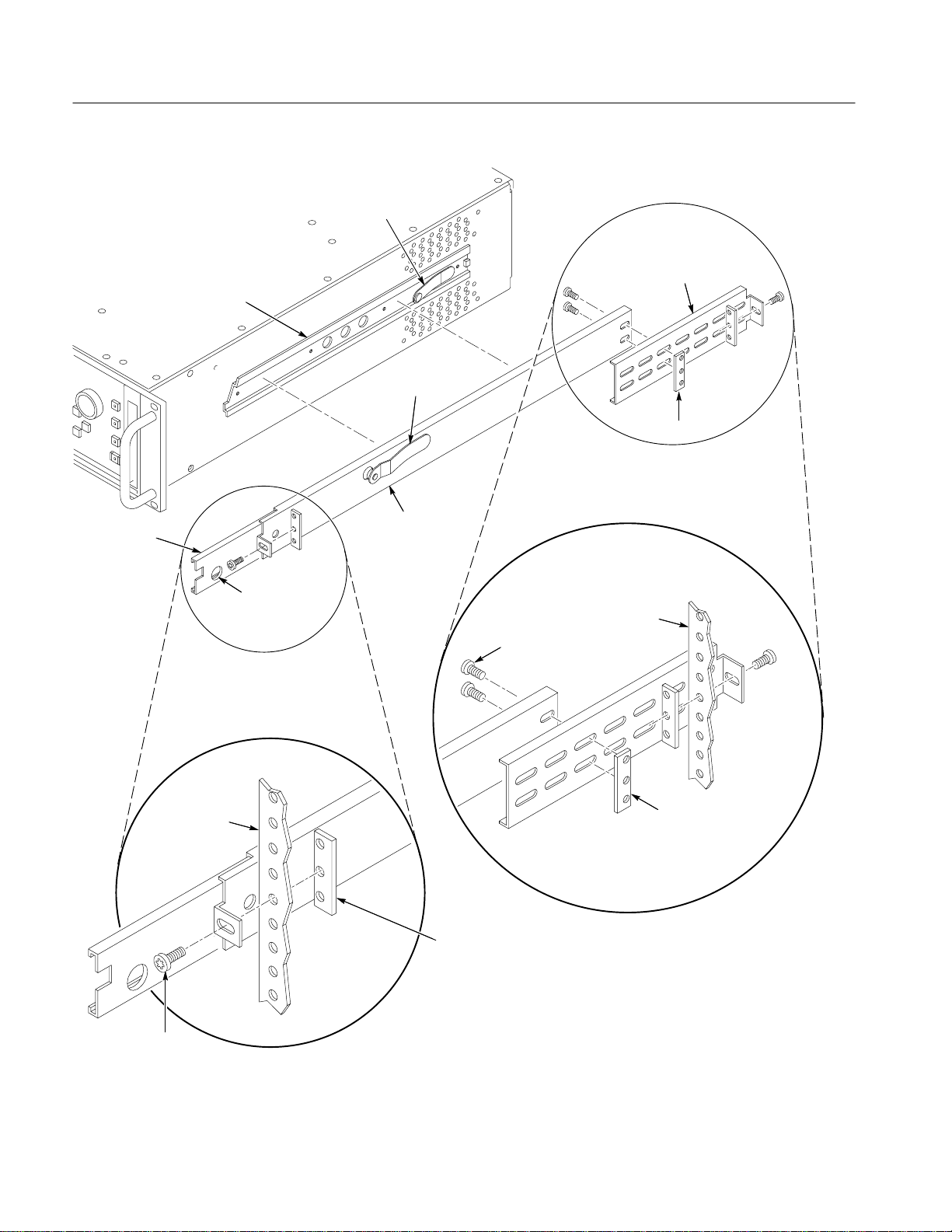
1. Connect the rackmount hardware to the rack, as shown in Figure 2–3.
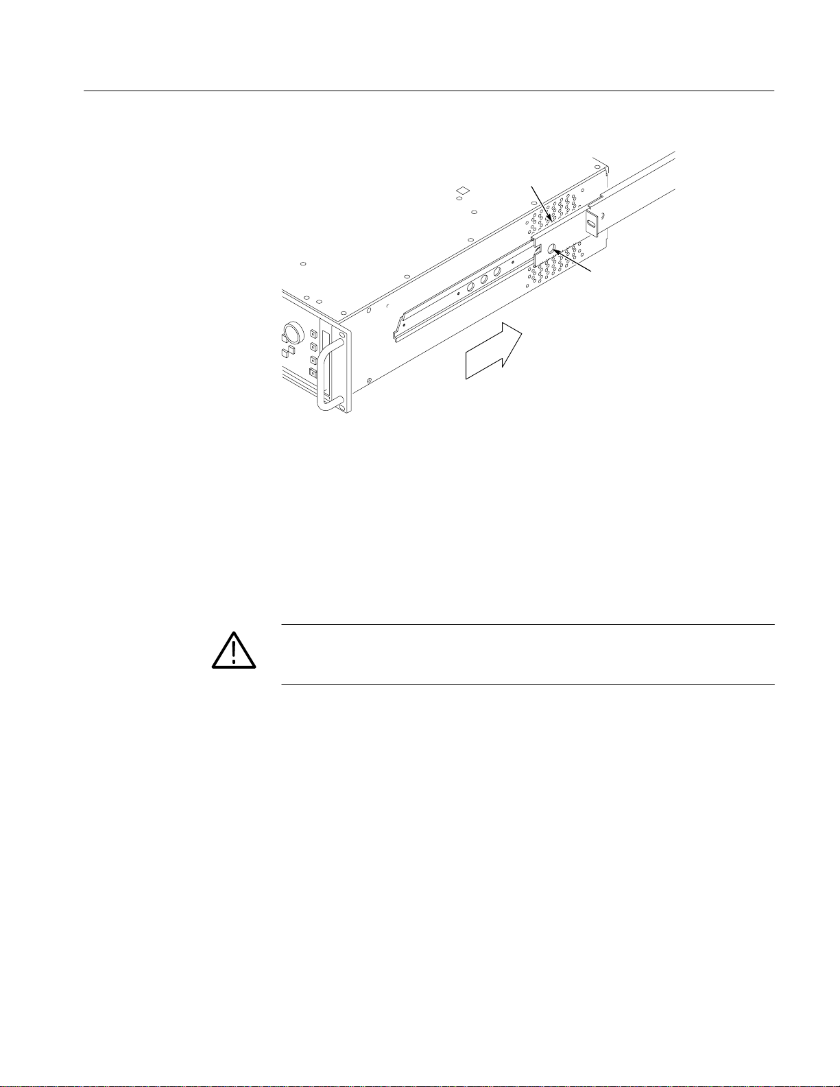
2. Carefully begin inserting the rack pieces attached to the TG 2000 Platform
mainframe into the pieces attached to the rack. See Figure 2–4.
WARNING. To prevent the TG 2000 Platform mainframe from falling and causing
injury to yourself and damage to the instrument, be sure that the stop latches
snap into position in the slide-out track on both sides of the instrument. See
Figure 2–4.
3. Support the instrument until the stop latches click into place on both sides.
4. Continue to slide the TG 2000 Platform mainframe completely into the rack.
TG 2000 Signal Generation Platform Service Manual
2–3
Page 28
Operating Information
Chassis section
Intermediate
section
Automatic latches
Rear mounting
bracket
Automatic latches
Flat bar nut
Stationary section
Front rack
10–32 Phs screw
Stop latch
hole
Rear rack
10–32 Phs screws
Flat bar nut
Flat bar nut
(Use if front rail
is not tapped)
Figure 2–3: Installing the rackmount hardware
2–4
TG 2000 Signal Generation Platform Service Manual
Page 29
Operating Information
Side-out track
Stop latch
Figure 2–4: Installing the TG 2000 Platform mainframe into the rack
Rackmount Removal. Perform these steps to remove the TG 2000 Platform
mainframe from the rack:
1. Disconnect the power cord and any attached cables from the rear of the
instrument.
2. Slide the TG 2000 Platform mainframe out until it stops at the catches.
WARNING. To prevent the TG 2000 Platform mainframe from falling and causing
injury to yourself and damage to the instrument, be sure that the stop latches
snap into position in the slide-out track on both sides of the instrument.
3. Support the TG 2000 Platform mainframe while you depress the stop latch
buttons on each side of the instrument. See Figure 2–4.
4. Provide support while you slide the TG 2000 Platform mainframe complete-
ly out of the rack.
TG 2000 Signal Generation Platform Service Manual
2–5
Page 30

Operating Information
Operating Information
This section contains instructions and procedures that will acquaint you with the
basics of operating the TG 2000 Platform mainframe so that you can perform
service on the instrument. Refer to the TG 2000 Signal Generation Platform
User Manual for detailed operating information.
This section includes instructions on the following topics:
Front-panel controls and indicators (page 2–6)
Using the touch screen (page 2–10)
Selecting test signals (page 2–12)
Using the disk drive (page 2–13)
Self Calibration (page 2–18)
Rear-panel connections (page 2–19)
Front-Panel Controls and
Indicators
Power-on procedure (page 2–21)
The primary method to control the TG 2000 Signal Generation Platform is to use
a combination of front-panel button and LCD display touch screen selections to
activate the functions within the instrument.
The secondary method to control the instrument is through the remote ports.
Refer to the user manual for detailed remote instructions.
The front-panel controls (see Figure 2–5) are divided into the following
functional sections:
System function
Keypad
Navigation
Miscellaneous function
After you select an instrument function, the selection may require a few seconds
to implement. A small hourglass icon is displayed in most cases while the
instrument implements your selection. Wait until the hourglass icon disappears
before you make another selection.
2–6
System Function. In most cases, when you push one of the System Function
buttons, a window opens on the LCD display providing touch-screen selections
related to the function of the button. For example, the Modules button displays a
window with selections that represent the installed generator modules.
TG 2000 Signal Generation Platform Service Manual
Page 31

Figure 2–5: Instrument front panel
Operating Information
The following buttons and windows are useful when you have a question about
the operation of the instrument:
Help. Displays a window that explains details about the displayed window.
Status. Displays the following information about all installed modules:
module type, name, slot location, format, and output signal.
The status of an installed AGL1 module is listed at the bottom of the display.
System problems, such as a module failing the power-up self test, are also
displayed in the Status window.
Utilities. Provides access to the following housekeeping functions and
information: date and time, versions of installed modules, front-panel
timeout period, self calibration, clock clients, and frame-reset clients. Refer
to page 2–18 for a self calibration procedure.
The Locked LED (located below the References button) has three states to
indicate the status of the genlock function.
Illuminated. The instrument is locked to the external reference.
Blinking. The instrument is attempting to lock or is unable to lock to the
external reference. Check that the incoming signal matches the type chosen
in the Reference Select window. Also, ensure that the signal line is properly
terminated at the AGL1 loop-through connector or at the distant equipment
connection. The status bar gives the current status.
Off. The instrument reference selector Int/Ext is set to Internal and the AGL1
module is not active, or the AGL1 module is not installed.
TG 2000 Signal Generation Platform Service Manual
2–7
Page 32

Operating Information
Keypad. Use the keypad to enter an exact quantity for a parameter. Use the scale
keys, such as k (kilo) and M (mega), to enter specific values. Table 2–2 shows
the purpose of each key.
T able 2–2: Keypad definitions
Key(s) Function
0–9 Enters numeric values
. Enters a decimal point
+/– Toggles the numeric value between positive and negative
p/T Enters the pico or Tera unit of measure
n/G Enters the nano or Giga unit of measure
m/M Enters the micro or Mega unit of measure
m/k Enters the milli or kilo unit of measure
Escape Exits out of data entry mode without changing the existing data
Back Sp Erases one character
EE Allows exponent entry. When entering a parameter value, enter a
number, press the EE key, and then enter the exponent value. For
example, press 4.2 EE 6 to enter the value 4.2x10
Enter Changes the parameter value to the new value
1
The instrument determines which of the two units is appropriate based on
the parameter being set.
1
1
1
1
6
.
Navigation Controls. The following navigation controls provide an alternative
method to touching onscreen display items to select them:
Arrow Buttons. Use these buttons to navigate through lists and objects on
the display and to move the cursor when entering text.
Knob. Use the knob to scroll through a list or to change a parameter setting.
Turn the knob to browse items in a window and to select characters in a text
entry window. When you have a numeric item selected, the knob will change
the value for the selected parameter. When you change a parameter, the
module output changes immediately.
Select. Use the Select button to confirm an entry or to make a browsed
selection active. Push the Select button repeatedly to sequence through items
within an icon when it contains several selections.
Touching a display item immediately activates the item. You can use the arrow
buttons and knob to move from item to item on the display without activating
them. This technique is known as browsing. To activate a browsed item, push the
Select button or touch the browsed display icon. See Figure 2–6.
2–8
TG 2000 Signal Generation Platform Service Manual
Page 33

Browsed item
Selected item
Operating Information
Figure 2–6: Browsed and selected display icons
Miscellaneous Function Buttons. The four buttons at the right edge of the front
panel provide the following functions:
Front Panel Enable. This button acts like a toggle switch to enable (LED on)
or disable (LED off) the front-panel keys, the knob, and the touch screen.
NOTE. The instrument turns the display off and disables the front-panel controls
when the front panel is not used for the specified timeout period. Push the Front
Panel Enable button to enable the front panel after it has timed out. Push the
Utilities button to access the timeout delay settings.
Remote. Push the Remote button to access control of the remote interfaces
through the Remote window. The following areas of control are available:
Serial Setup. This selection provides control of the serial RS-232
interface.
Parallel Setup. This selection provides control of the parallel interface.
Remote Only. This selection locks out the front-panel controls when
remote-only operation is desired. Touch the Quit icon in the Remote
Only window to return to front-panel operation.
Remote Port. This selection selects an interface port. You must select an
interface port before using it for transferring data or commands. Touch
the Remote Port icon repeatedly to cycle through the selections.
TG 2000 Signal Generation Platform Service Manual
2–9
Page 34

Operating Information
GPIB Setup. This selection lets you set the GPIB configuration. This
selection is only available when the GP1 module is installed.
Screen Contrast. When screen contrast is active (LED on), rotate the knob to
adjust the screen contrast for the best viewing in your environment.
On/Standby. Push the On/Standby button (LED on/LED off respectively), to
turn the instrument off after all critical processes have been completed. This
leaves the instrument in a known state. The On/Standby button is different
than the rear-panel power switch, which immediately shuts off power to the
instrument regardless of any functions that are in process.
When the On/Standby button is set to On, the battery system charges at the
highest rate. When the button is set to Standby and the rear-panel power
switch is on, the battery system charges at a low or trickle rate.
Using the Touch Screen
The LCD display serves as a touch screen that lets you touch display icons to
make functional selections. Touching a display icon either selects the item or
displays additional selections.
The following features appear in the touch-screen windows. See Figure 2–7.
Icons. Icons are display symbols that represent and show the status of test
signals or other selectable items. Touching some display icons repeatedly
cycles through the available selections.
NOTE. Icons of the same function can appear as selections in more than one
window. For convenience, icons appear where they are functionally appropriate.
Status Bar. The Status Bar shows the active signal set and test signal for the
selected module (BG1:2 in Figure 2–7). The status bar also gives the status
of other functions, such as signal transfers.
Window Title. The Window Title shows the window name, which indicates
the selected function.
Slot: #. The slot number identifies the physical location of the selected
module to remind you which module outputs are being controlled. In
Figure 2–7, note that the slot # matches the “2” in the active module name,
BG1:2.
2–10
List box. Touch the List Box to show additional selections that are available
within a display icon, such as a list of test signals. To display the list box
selections, rotate the knob or touch the list box. To select a list box item, use
the cursor keys or the knob to highlight a selection, and then push the Select
button. Touch an open list box to close it without making a selection.
TG 2000 Signal Generation Platform Service Manual
Page 35

Signal set and name
of active signal
Selected item
Selectable items
List box
Operating Information
Location of the selected
Window titleStatus bar
module within the mainframe
Figure 2–7: Main display features
Page or << Page >>. Touch the Page icon to access the previous or following
page of display selections.
Quit/Save. Touch the Quit or the Quit/Save icon to return to a previous
display window. If you have made changes, you will be asked if you want to
save them. If you have changed a test signal, you will be prompted to enter a
signal name. The signal name you enter will always be preceded by an
underscore character to indicate a user-created test signal.
Reset. Touch the Reset icon to return a parameter setting to the value it had
when you entered the window.
Hourglass. A small hourglass icon is displayed in most cases when the
instrument is taking time to implement your selection. Wait until the
hourglass icon disappears before you make another selection.
TG 2000 Signal Generation Platform Service Manual
2–11
Page 36

Operating Information
Selecting Test Signals
The System Function buttons named Module, Signal Sets, and Test Signals
provide access to the output signals. These buttons allow you to select a module,
a signal set within the module, and a particular test signal. After selecting a test
signal, you can set common module parameters and signal parameters for
individual signals. Figure 2–8 shows this test signal hierarchy.
Modules
Signal Sets
Test Signals
Module
Parameters
Signal
Parameters
Figure 2–8: Module and test signal hierarchy
Each module has a Module Parameters selection for parameters that apply to all
appropriate test signals from that module. Each test signal also has unique
parameters controlled through the Signal Parameters icon.
Shared Module Memory. Generator modules of the same type share their onboard
memory spaces to provide larger signal-storage areas. Signals stored on one
module can be loaded and output by other modules of the same type.
When you remove a module, the signals stored on the module are no longer
available to the remaining modules. Before removing a module, copy all signals
for the module type to a floppy disk. After removing the module, you can reload
removed signals from the disk providing there is enough free memory space to
load the signals.
2–12
TG 2000 Signal Generation Platform Service Manual
Page 37

Operating Information
Using the Disk Drive
The disk drive provides a way to load and save signal sets and sequences for a
module. You can also save all current settings, called presets, for the mainframe
and its modules to the disk. The disk drive uses 3.5 inch, 1.44 Mbyte, MS-DOSformatted disks. The disks must be formatted before using them in the drive.
Supported File Types. The disk drive reads and writes several types of files that
support different functions. The following file types are supported:
Signal Sets. These files contain directories of signal groups and, at the
lowest level, test signals. Signal set files have a .dnl suffix and may contain
test signals for more than one type of module. Use the SDP2000 Signal
Development Program software to create signal sets and assign them to a
module type. You can also save signal sets from a module to the disk.
Presets. These settings files are stored in a special binary format that is
unique to each type of module. The settings can be saved to disk and
restored later.
Sequences. These are TCL files stored as ASCII text, which is readable by
any text editor. Sequence files contain a series of SCPI and TCL commands
that are entered using a text editor. Sequence files have a .seq suffix.
To specify a sequence file to run at instrument power on, load a sequence file
named AUTOSTRT into the instrument. At power-on, the instrument checks
the disk drive first and then the internally-stored sequence files for one
named AUTOSTRT. The instrument will automatically execute the contents
of the first AUTOSTRT file it finds.
Saving Signals to Disk. Test signals that can be output from a module can be
saved onto a disk. You should save all signals in a module to a disk before
removing the module. Modules will lose their signal memory after 30 seconds
when you remove them from the mainframe.
To save signals to a disk, follow these steps:
1. Insert a preformatted disk into the drive. Ensure that the disk is not write
protected.
2. Push the Disk button to open the Disk window and then touch the Save
Signals to Disk icon.
3. Touch the Select Source icon to display a window like the one in Figure 2–9.
4. Select a module type (such as AVG1 at the left of the display) by highlight-
ing it with the arrow buttons, and then pushing the Select button. Move right
to select the signals you want to save to a disk file.
TG 2000 Signal Generation Platform Service Manual
2–13
Page 38

Operating Information
Signals are displayed in a hierarchical list with the top of the list shown at
the left under the Signals header. The value Total Tagged: is the combined
size of the selected signals.
If there are more signals than will fit on one disk, use multiple disks and
select a smaller group of signals to save on each disk.
Figure 2–9: Selecting the Save Signals to Disk source
5. Touch Quit/Save when you have selected the signals to save to disk.
6. In the Save Signals to Disk window, touch Select Destination.
7. You can use the New Dir icon to create a directory on the disk. Otherwise,
touch the New File icon and give the output file a name. In Figure 2–10, a
directory named local was created, and then a file named test1 was created.
8. When the source and destination of the test signal are entered, you can save
the signals to disk. Touch the Start Save icon to begin the save process.
Saving signals to disk takes a brief length of time that depends on the
number and size of the signals you are saving.
2–14
TG 2000 Signal Generation Platform Service Manual
Page 39

Operating Information
Figure 2–10: Selecting a Save Signals to Disk destination
Replacing Signals from Disk. You select Replace Signals from the Disk window
to load new signals in place of the currently installed signals for a module type,
such as the AVG1.
CAUTION. To prevent data loss, use caution with the Replace Signals function.
All signal sets currently loaded in the selected module type are DELETED, and
the replacement signals are then loaded into the selected module type. You
should consider saving all the signals in a module type to disk before using the
Replace Signals function.
Follow these steps to replace all signals for a type of generator module, such as
all installed AVG1 modules, with signals from a disk:
1. Insert a disk containing the signal sets into the disk drive.
2. Push the Disk button to open the Disk window, and then touch the Replace
Signals icon.
3. Use the arrow buttons to highlight the signal file you want to load, and then
press the Select button. In Figure 2–11, the file TEST1.DNL is selected.
4. Touch the Quit icon after you have selected the signal file.
5. The signals contained in the signal file (TEST1.DNL in this example) are
displayed in a hierarchical structure. Use the arrow buttons to select the
signals that you want to load. The displayed value Available: indicates the
free module memory remaining after the selected signals are loaded.
6. Touch the Start Replace icon to load the selected signals into the memory of
the compatible modules.
TG 2000 Signal Generation Platform Service Manual
2–15
Page 40

Operating Information
Figure 2–11: Replacing test signals from disk
Adding Signals from Disk. To add signals to a module from the disk drive, follow
these steps:
1. Insert the disk with the test signals into the disk drive, and then push the
Disk button to open the Disk window.
2. Touch the Add Signals icon, and then touch Select Source.
3. Select the signal set file from A: drive and then touch the Quit/Load icon.
4. Select the signals that you want to add from the signal set file. In Fig-
ure 2–12, the Linearity signals under PAL1 are selected. When you have
selected the signals you want to add, touch the Quit/Load icon, and then
touch Quit/Load again to return to the Add Signals window.
2–16
TG 2000 Signal Generation Platform Service Manual
Page 41

Operating Information
Figure 2–12: Selecting the source signals to add from disk
5. Touch the Select Destination icon, and then select the type of destination
module. If you are loading a single test signal, select the destination at the
top of the hierarchy and it will be placed in an appropriate lower folder. You
can also pick a bottom level folder for the destination.
If a mismatch between the source and destination hierarchy occurs, the
following error appears: “This selection is too deep given the source.” Try a
destination at a higher level in the hierarchy and let the TG 2000 Platform
mainframe pick the appropriate level to add the signal.
6. When you have selected the destination for the test signal you are adding,
touch the Quit/Load icon to return to the Add Signals window.
7. In Figure 2–13, the source file SPECIAL is selected from the disk drive. The
destination module type is AVG1, and the point in the hierarchy is PAL 1.
Note that the value Total Tagged: is the size, in kilobytes, of the files to be
loaded. The value Free: is the size, in kilobytes, of the free memory space on
the AVG1 module. If the Tagged value exceeds the Free value, the module
will not have enough memory space to contain the new signals. Reduce the
number of signals being loaded (Select Source) or delete a few signals from
the module (Delete Signals) to free signal space.
8. Touch the Start Load icon to transfer the signals into the destination module.
TG 2000 Signal Generation Platform Service Manual
2–17
Page 42

Operating Information
Figure 2–13: Add Signals window with source and destination selected
Deleting Signals. To delete signals from a module, follow these steps:
Self Calibration
1. Push the Disk button to open the Disk window and then touch the Delete
Signals icon.
2. Select the test signals or signal sets you want to delete. The value Total
Tagged: indicates the memory used by the selected signals.
Note that the custom signal files you create contain only signal-difference
data referenced from an original signal. The custom signals have a .sig suffix
and cannot be deleted without deleting the original signal.
3. Touch the Delete icon to remove the selected signals from the module.
This function performs an auto calibration of the selected modules. Self
calibration does not require any external test equipment, though all output
connections of the modules to be calibrated must be terminated into 75 W.
Perform self calibration on a module anytime it has been replaced to ensure
proper performance of the generator. Refer to the module user manual for
information about any special setup necessary before starting self calibration.
NOTE. All installed modules have their outputs disabled during the calibration of
any module.
2–18
Allow a 20 minute warm-up period before performing self calibration.
TG 2000 Signal Generation Platform Service Manual
Page 43

Operating Information
To calibrate one or more modules, follow these steps:
1. Push the Utilities button and touch the Module Self Cal icon.
2. Touch the module icons that you want to calibrate. Any or all modules may
be selected for calibration.
3. Ensure that all signal outputs for the selected modules are properly termi-
nated into 75 W. (You do not need to terminate the Trigger outputs of any
module and the BG1 module outputs.)
4. Touch the Start Cal icon to begin calibration of the selected modules. The
number of modules selected determines the time required for calibration.
5. Check that no errors are displayed during calibration. Refer to Maintenance
on page 6–37 for troubleshooting information.
Rear-Panel Connections
Figure 2–14 shows the rear-panel connections for the TG 2000 Platform
mainframe. Connections to modules in slots 2 through 10 are discussed in the
appropriate module user manuals.
You must select an interface port before using it. To select the interface port,
push the Remote button, and then touch the Remote Port icon repeatedly to cycle
through the available choices.
AC Power. For important information on the AC power connection, fuse, and
line selector, refer to Electrical Installation on page 2–1.
RS-232
interface
Parallel
interface
0
AC
Power
CPU
Module
Figure 2–14: Rear-panel connectors
TG 2000 Signal Generation Platform Service Manual
1098 7654321
Clock
Module
2–19
Page 44

Operating Information
RS-232 Interface (Serial). This is a standard RS-232 interface for remote control
of the TG 2000 Platform mainframe and all installed modules. The RS-232
connector (on the CPU module) is a 9-pin, subminiature, D-type connector with
male contacts. The pin descriptions are shown in Figure 2–15.
To use the interface, connect the 9-pin serial/RS-232 output of your PC to the
9-pin RS-232 connector on the rear panel of the mainframe, using a 9-pinto-9-pin straight-through cable. If necessary, a 25-pin connector can be used, in
conjunction with a 9-pin-to-25-pin adapter.
Refer to the TG 2000 Signal Generation Platform User Manual for programming information.
Data connection at TG2000
mainframe rear panel
6
9
RS–232
Pin
number
1. Not used
2. RXD (Received Data)
1
5
3. TXD (Transmitted Data)
4. Not used
5. Ground
6. DSR (Data Set Ready)
7. RTS (Request To Send)
8. CTS (Clear To Send)
9. Not used
Figure 2–15: RS-232 connector pin descriptions
Parallel Interface. The parallel interface is a 25 pin D-type connector on the CPU
module. The main purpose of the Centronics-compatible port is for transferring
signal sets from the SDP2000 Signal Development Program software into the
generator modules.
NOTE. For proper operation of the parallel interface, ensure that all 25
connector pins are connected straight through your cable.
2–20
GPIB Interface. The optional GP1 Interface module provides a GPIB interface.
For information on this interface, refer to the GP1 Interface Module User
Manual.
TG 2000 Signal Generation Platform Service Manual
Page 45

Operating Information
Power-on Procedure
The following procedure describes how to check that the TG 2000 Platform
mainframe powers on properly.
1. Before applying power to your TG 2000 Signal Generation Platform, check
the following items:
a. Check for proper installation. Refer to Installation on page 2–1.
b. Check that the power cord is connected to the AC line source.
2. Set the rear-panel Power switch to on.
3. Push the front-panel On/Standby button to apply power.
During power-on, the TG 2000 Platform mainframe performs a self test to
verify functionality. The self test requires a minute or less to complete,
depending on the number of modules installed. The front-panel display will
be on with no displayed errors after the self testing successfully completes.
If your TG 2000 Platform mainframe powers on, but an installed module
fails to appear in the Modules window, refer to Maintenance for troubleshooting instructions.
4. Once the power-on self tests are complete, the TG 2000 Platform mainframe
recalls the settings that were active when the instrument was powered off.
The power-on settings are stored in nonvolatile memory.
5. When you first power on the TG 2000 Platform mainframe after shipment or
long storage, leave the front-panel On/Standby button set to on (LED on) for
12 hours to fully charge the system batteries. The batteries maintain the test
signal data NVRAM when the mains power is disconnected.
NOTE. If backup power is lost, you must reload the test signal data into NVRAM
from the disks supplied with your user manual or through a remote port. After
reloading the test signal data, run a self calibration on all modules.
TG 2000 Signal Generation Platform Service Manual
2–21
Page 46

Operating Information
2–22
TG 2000 Signal Generation Platform Service Manual
Page 47

Page 48

Theory of Operation
This discussion provides an overview of the main components of the TG 2000
Signal Generation Platform. This discussion covers general interactions with the
modules. For information about a specific module, refer to the user manual for
that module.
Block Level Description
Figure 3–1 shows a simplified block diagram of the TG 2000 Signal Generation
Platform
External
Reference
(optional)
With AGL1 Option
Front
Panel
Disk
Drive
Remote
Control
RS-232
Parallel
GPIB
Genlock
Mainframe
CPU
Memory
Clock
CPU
Bus
Clock
Bus
Generator
Module
Signal
Memory
Generator
Module
Signal
Memory
Modules
Black
Burst
Module
Signals
Out
Signals
Out
Nine
Slots
Signals
Out
Figure 3–1: Simplified block diagram
System Control
As shown in Figure 3–1, the mainframe CPU coordinates front panel and remote
interface commands and uses that input to set up the modules, the clock, and the
optional AGL1 Genlock module. The CPU sends data and control messages over
the CPU bus to set up the generator modules to perform a function, such as load
a test signal into module memory or change the output configuration.
TG 2000 Signal Generation Platform Service Manual
3–1
Page 49

Theory of Operation
Power Supply
Disk Drive
Remote Control
Generator Modules
The 220 W power supply has a rear-panel switch to select between 115 V and
230 V operation.
The power supply delivers voltages to the various modules and mainframe
components and to the two cooling fans. The rear-panel switch is a hard power
switch, while the front-panel switch is a soft power switch.
The disk drive provides an easy way to load signal sets, presets, sequences and
other data. It also provides a way to export the same types of data. The drive
supports 1.44 Mbyte, MS-DOS format disks. The complete signal sets for each
module type are shipped with the module on 3.5 inch disks.
Most front-panel control functions can be remotely controlled using the RS-232
or optional GPIB port. A computer or other controller sends SCPI compatible
commands to set up the mainframe or a specific module. Each module must be
individually set up, using its own set of commands. The mainframe and modules
use some of the same commands, but each also has unique commands. The SCPI
command set for each module is described in section 3 of the module user
manual.
There are eleven module slots in the mainframe. The Clock and CPU modules
are required for system operation and permanently occupy two special slots (they
must be installed in these slots). The BG1 Black Burst Generator module is also
a standard component of the mainframe, but it can be moved or replaced with
another module if desired. Without the BG1 Generator module, optional AGL1
Genlock module or optional GP1 Interface module, there is room for nine
generator modules. Any combination of different generator modules and/or
multiples of the same generator module may be used.
3–2
Signal Memory
Battery Backup for
NVRAM
Most generator modules contain NVRAM for storing test signals. The test
signals are initially loaded from the supplied disks or through the parallel or
RS-232 port into NVRAM. The signal that is selected for output is loaded into
fast memory on the module. The loaded signal configures the module to
immediately output the selected signal. The flexible memory architecture allows
one generator module to output signals stored on another module of the same
type. Installing four of the same type of module, such as the AVG1 Generator
module, provides four times the signal storage space. All four modules have
equal access to this expanded memory space.
A central rechargeable battery maintains NVRAM data in the mainframe and
modules when AC power is not connected. The power supply quick charges the
battery while the instrument power is on. When the instrument is turned off
using the front-panel On/Standby switch, the battery is trickle charged. The
battery is not recharged while the rear-panel power switch is off.
TG 2000 Signal Generation Platform Service Manual
Page 50

Theory of Operation
The power drain on the battery is low enough to allow module memory to
remain intact for many months. When you add more modules or modules that
use more power, the length of time that the memory remains intact is shortened.
In the event of memory failure from power loss, reload the signal memory
(NVRAM) from the supplied disks or through a remote port, and then run self
cal on all modules.
NOTE. When you first turn on the mainframe, leave it turned on for at least 12
hours to fully charge the backup battery. Do this also after you replace the
backup battery.
Clocks and Frame Reset
Signals
The 27 MHz master clock synchronizes the clocks and frame reset pulses that
control module timing, as shown in Figure 3–2. The Clock module provides
three high-speed clock signals, one at 27 MHz, and two at rates from 10 MHz to
100 MHz. In addition, there are two frame resets which allow different modules
to operate in separate television standards, such as PAL and NTSC.
The TG 2000 Signal Generation Platform can generate different standards, such
as PAL and NTSC, at the same time, using the 27 MHz or the two adjustable
clocks and the two frame reset pulses. The clocks and frame reset pulses ensure
that all modules driving the same format remain synchronized. The CPU
configures the clock to generate the clock frequencies and frame reset pulses
needed to support the different video formats.
TG 2000 Signal Generation Platform Service Manual
3–3
Page 51

Theory of Operation
CPU Bus
Black Burst In
Black Burst In
Sine Wave
(optional module)
Temperature Controlled
Master Oscillator
(27 MHz)
AGL1
Genlock
Preset
Frame
Counter
Reset
Digital
Frequency
Synthesizer
Frame
Counter
Reset
Digital
Frequency
Synthesizer
Frame Reset 1
Clock 1
Frame Reset 2
Clock 2
27 MHz Clock
Figure 3–2: Block diagram of the clocks and frame reset signals
External Reference
Genlock
An external reference may be used by the optional AGL1 module to lock on one
of several video standards. All modules using the same standard as the AGL1
Genlock module are locked to the external reference. Refer to the AGL1 Genlock
module user manual for a list of the supported formats.
Module Timing Delay
Most generator modules can be separately timed with respect to the system. This
is accomplished by applying a precise, variable delay to the system clocks and
frame resets as they enter the module. For conventional television, the adjustment range is effectively infinite, providing adjustment over a complete color
frame.
An adjustable trigger output is available on some modules to synchronize
external test equipment to any location in the test pattern.
Timing References
The TG 2000 Signal Generation Platform supports internal or external references
and signal delay relative to this reference. Video reference signals synchronize
the start of test signals of the same type, such as NTSC or PAL. The AGL1
module is required to use external references.
3–4
TG 2000 Signal Generation Platform Service Manual
Page 52

Theory of Operation
System delay and module timing delay are available to adjust for different signal
path delays in an operating environment. System delay uses the optional AGL1
module to lock the system to an external reference signal. Once the reference is
defined, you can add a common delay to all modules that generate the same
format as the external reference.
Module timing delay, which is available with some modules, allows the delay of
one module from other modules that generate a compatible format. Module
timing delay does not require an AGL1 module.
Figure 3–3 shows the effects of the system delay and the individual module
delay. Note that the BG1 module is at time zero for intermodule timing because
it does not support module delay. In Figure 3–3, the BG1 module and AVG1
output signals are delayed 5 ms by the AGL1 module. The AVG1 module is
delayed an additional 15 ms by the AVG1 module system delay timer.
External
reference black
burst signal
BG1 Module
AVG1 Module
15 s
5 s Genlock
delay
module
delay
20 s total
AVG1 delay
Figure 3–3: Comparison of module delay and system delay from a reference
TG 2000 Signal Generation Platform Service Manual
3–5
Page 53

Theory of Operation
Timing Delay Block
Diagram
System Reference Delay
with the AGL1 Module
Figure 3–4 shows how the module delay is implemented for the generator
modules that support it. They have the ability to delay the clock and frame reset
pulse for half a frame. The delay is by a number of vertical lines plus a
horizontal delay up to the duration of one scan line. The delay is set in the
Module Timing window. (The variable system clocks also support module
delay.)
DVG1
Module
Clock
27 MHz Clock
Frame Reset 1
Frame Reset 2
BG1
Module
AVG1
Module
Delay Delay Delay
AVG1
Module
Figure 3–4: Block diagram of module timing delay
Figure 3–5 shows how the AGL1 Genlock module can delay its lock signal to
effectively delay the clock and frame pulses to all modules. Delaying the clock
and frame pulses results in a corresponding delay in the module output. All
generator modules using the same standard are affected equally by this delay.
VCO control
Frame signals
External
Video IN
AGL1
Genlock
Module
ClockDelay
Clock
Figure 3–5: Block diagram of the AGL1 Reference timing delay
3–6
TG 2000 Signal Generation Platform Service Manual
Page 54

Page 55

Performance Verification
Perform the procedures in this section to verify the operation of the TG 2000
Platform mainframe. You do not need to remove the covers from the mainframe.
Verification Interval
To ensure correct instrument operation, perform these procedures once a year.
Before performing any procedures, complete all relevant maintenance procedures
outlined in the Maintenance section of this manual.
Test Equipment Required
Required equipment is shown in Table 4–1. Equipment suggestions are given in
the example column. You can substitute other equipment if it meets the
requirements in the Minimum specification column. If you do not have the
required equipment, you can return your instrument to a Tektronix service center
for performance verification.
T able 4–1: Test equipment required for verification
Equipment Minimum specification Purpose Example
Frequency counter Accuracy and resolution to 8 decimal places, or
used with an external reference (WWV , Loran C,
or GPS) that will improve the accuracy to 8
decimal places. Frequency 27 MHz.
75 W coaxial cable
Autotransformer Voltage range appropriate for the voltage range
3.5 inch disk High density, DOS formatted Check disk drive operation
IBM-compatible PC Able to load and run the SDP2000 Signal
SDP2000 Signal Development Program software
and user manual
Parallel cable 25 pin D-type connector Check the parallel interface 012-1214-XX
Serial cable 9-pin subminiature D-type connector Check the serial interface 012-0911-XX
BNC connectors; 1-meter length Check clock frequency 012-0074-00
to be tested
Development Program. See its user manual for
requirements.
Standard accessory that is shipped with the
mainframe
To check the clock frequency.
(This is checked in more detail
in the BG1 Black Burst Gener-
ator Service Manual.)
Check input voltage range Variac – W10MT3W
Check the remote interface
(parallel and serial)
Check the remote interface
(parallel and serial)
T ektronix CDC250
Counter
Four disks, shipped
with the SDP2000
manual
TG 2000 Signal Generation Platform Service Manual
4–1
Page 56

Performance Verification Procedures
Preparation
1. Install all modules into the mainframe if they are not already installed.
2. Power on the mainframe by setting both the rear-panel POWER switch and
3. Allow the mainframe and modules to warm up for at least 20 minutes before
Verification Procedures
Installation instructions appear on page 2–1.
front-panel ON/STANDBY switch to on.
performing any tests.
Check Input Voltage
Range
You can use this procedure to check either the 115 V or 230 V voltage range.
T est Equipment Required: You will need an autotransformer for this test. A
waveform monitor is optional (for step 6.).
Procedure: Check Input Voltage Range
1. Set the TG 2000 Platform mainframe rear-panel POWER switch to off.
2. Make sure that the TG 2000 Platform mainframe is set for the voltage that
you want to check (115 or 230 V) and that the appropriate fuse is installed.
Use the 6 A fuse (159-0342-XX) for 115 V, and the 3 A fuse (159-0005-XX)
for 230 V.
3. Connect the mainframe power cord to the autotransformer.
4. Power on the autotransformer and set it for the nominal voltage you want to
check (either 115 or 230).
5. Power on the TG 2000 Platform mainframe, both the rear-panel POWER
switch and the front-panel ON/Standby switch.
6. Vary the autotransformer from 87 to 132 V or from 174 to 250 V and check
that the instrument operates across the voltage range. (For greater confidence, hook up the video outputs to a waveform monitor and check for a
stable display of the video signal on the waveform monitor display while
varying the voltage to the mainframe.) If the front-panel display disappears,
proceed to Troubleshooting in Section 6 of this manual.
4–2
7. Unplug the mainframe from the autotransformer. Make sure the mainframe
power setting and fuse are appropriate for your AC power source, and then
plug the mainframe into the AC power source.
TG 2000 Signal Generation Platform Service Manual
Page 57

Performance Verification Procedures
Check Fan Operation
Check CPU Module
The TG 2000 Platform mainframe contains two fans, which should remain in
operation while the mainframe is operating.
Procedure: Check Fan Operation
Inspect the mainframe while it is operating to be sure that both fans are
operating. You should be able to hear the fans, and to feel vibration on the sides
of the mainframe cabinet. If either fan is not operating, proceed to Troubleshoot-
ing in Section 6 of this manual.
Use the following procedures to check the operation of the CPU module.
T est Equipment Required:
IBM compatible computer
SDP2000 software and user manual
Serial cable
Parallel cable
Blank disk
Procedure: Check Disk Drive
Create a directory named “test” on the disk as follows:
1. Insert the disk into the mainframe disk drive.
2. Push the Disk button to enter the Disk window.
3. Touch Save Signals to Disk on the display. See Figure 4–1.
Figure 4–1: Save Signals to Disk window
TG 2000 Signal Generation Platform Service Manual
4–3
Page 58

Performance Verification Procedures
4. Touch Select Destination on the display.
5. Touch New Dir on the display.
6. Create a directory named “test” by touching the letters t e s t on the display.
See Figure 4–2. If you make a mistake, touch BS to back space.
Figure 4–2: New Directory window
7. Touch OK on the display.
8. Check that the new directory appears in the second column under Directories of the Save Signals to Disk window as shown in Figure 4–3. If the
directory does not appear, check that your disk is not write protected or try a
new formatted disk. Continued failure may indicate a defective disk drive.
4–4
Figure 4–3: New directory named Test
TG 2000 Signal Generation Platform Service Manual
Page 59

Performance Verification Procedures
Procedure: Check Front-Panel Interface
This procedure checks the front-panel buttons and touch screen operation. It also
checks the time and date setting.
1. Check that the On/Standby LED is lighted.
2. Check each front-panel button with an LED (except for the On/Standby
button) to be sure that the LED lights when you push the button. Follow
these special instructions:
a. Listen for a ‘beep’ sound each time you push a front-panel button. This
indicates that the button is making contact.
b. After checking the Enable front-panel button, be sure to leave it in the
enabled position (LED on) so that you can continue to use the front-panel interface.
c. To check the Edit button LED, push the Modules or List button followed
by the Edit button.
d. Some of the front-panel buttons remain selected until you select another
system function button. For example, to exit the Remote or Modules
mode, you must push another front-panel button.
3. Push the Utilities button. Push each of the four directional arrow buttons on
the front panel and check that the displayed highlight moves accordingly.
4. Use the directional arrows to highlight Set Date/Time on the display, and
then push the Select button.
5. Check that the date and time are correct. If not, select each parameter and
adjust it, using the knob or front-panel keyboard.
If this clock does not keep time from power off to power on, refer to
Troubleshooting in the Maintenance section of this manual.
6. Touch Load on the display.
7. Touch Quit on the display.
8. Push the Presets button.
9. Touch Presets on the display.
10. Touch Create on the display.
11. Touch a, b, c, d, e, f, g, and h on the display. Listen for a ‘beep’ as you
touch each character. Touch BS to back space over the letters you typed.
Repeat with the rest of the alphabet.
12. Touch Cancel on the display. Touch Quit on the display.
TG 2000 Signal Generation Platform Service Manual
4–5
Page 60

Performance Verification Procedures
Procedure: Check LCD Contrast
1. Push the Screen Contrast button.
2. Turn the knob to vary the screen contrast. Be sure it works smoothly over the
3. Leave the contrast set as desired for best viewing.
4. Push the Screen Contrast button again. The LED will go off.
Procedure: Check Serial and Parallel Ports
Use the SDP2000 Signal Development Program software to check that the serial
and parallel ports are functional.
1. Install the SDP2000 software according to the instructions in the SDP2000
2. Using the 25-pin cable, hook up the TG 2000 Platform mainframe parallel
adjustment range.
Signal Development Program User Manual.
port to a parallel port on your PC.
3. On the TG 2000 Platform mainframe, choose the parallel port as follows:
a. Push the Remote button.
b. Check the Remote Port selection at the bottom of the display. If it does
not already read Parallel, touch it once to toggle the setting to Parallel.
4. On the PC, perform the following tasks:
a. Open the Tek group (it may already be open from installation) and then
double click on the TGCOMM icon to open the communications portion
of the SDP2000 program.
b. To make the View menu commands available, open a .dnl file as
follows:
In the File Open dialog box, select the working directory that you
specified during SDP2000 installation.
Specify .dnl files in the List Files of Type box to display only
download files.
Open any .dnl file. One example is the file named
SDP2000/dvg1/dnls/525–1431.dnl.
c. From the Options menu, choose Parallel settings. Select the parallel port
you are using (Lpt 1, Lpt 2, or Lpt 3).
4–6
d. From the View menu, pull down the TG 2000 Signals command and
choose Parallel.
TG 2000 Signal Generation Platform Service Manual
Page 61

Performance Verification Procedures
5. Check that the TGCOMM displays the list of TG 2000 signal names in the
right side of the window. The time it takes for the list to appear will vary
based on the speed of the PC. If the list does not appear, check the settings
and cable connections, cycle the TG 2000 Platform mainframe power and
restart the TGCOMM program. If the TGCOMM still does not display the
TG 2000 signal names, it could indicate a problem with the parallel port.
6. Disconnect the parallel cable and connect the serial cable between the
TG 2000 Platform mainframe serial port and a serial port on your PC. Be
sure that the CTS and RTS lines (pins 7 and 8 on the 9-pin serial connector)
are connected.
7. On the TG 2000 Platform mainframe, perform the following tasks:
a. Push the Remote button.
b. Touch Serial Setup on the display.
c. Note the Baud Rate.
d. Set the Flow Control to CTS/RTS and select Computer mode.
Check 27 MHz Clock
Frequency
e. Touch the Remote Port selection at the bottom of display to toggle the
setting to Serial.
8. On the PC, perform the following tasks:
a. From the Options menu, choose Serial settings. Set the baud rate to
match the setting noted on the TG 2000 Platform mainframe and select
the serial port that you are using (COM1, COM2, COM3, or COM4).
b. From the View menu, pull down the TG 2000 Signals command and
choose Serial.
9. Check that the TGCOMM displays the list of TG 2000 signal names in the
right side of the window. If the list does not appear, check the settings and
cable connections, cycle TG 2000 Platform mainframe power and restart the
TGCOMM program. If the TGCOMM still does not display the TG 2000
signal names, it could indicate a problem with the serial port.
T est Equipment Required:
Frequency counter
75 W coaxial cable
BG1 Generator module installed in the TG 2000 Platform mainframe. If you
do not have this module installed, you can use the adjustment procedure on
page 5–5 to check the clock frequency.
TG 2000 Signal Generation Platform Service Manual
4–7
Page 62

Performance Verification Procedures
Procedure: Check 27 MHz Clock Frequency
1. Connect the Clock output and warm up instrument as follows:
2. Set the TG 2000 Platform mainframe as follows:
a. Connect the Clock output from the BG1 Generator module to the
frequency counter as shown in Figure 4–4.
b. Connect the external reference to the frequency counter if needed (refer
to Table 4–1 on page 4–1).
c. Make sure that the mainframe and modules have warmed up for at least
20 minutes. If an AGL1 Analog Genlock module is installed, make sure
that the TG 2000 Signal Generation Platform is set to internal reference.
a. Push the Module button and touch BG1 on the display.
b. Touch NTSC on the display.
c. Touch Black Burst on the display.
d. Touch Module Parameters on the display.
e. Touch Clock Out on the display.
f. If the clock frequency is not set to 27.0 MHz, record the frequency
setting. You will restore this setting in step 5. Then press 2 7 /M and
Enter on the keypad. This sets the output frequency to 27.0 MHz.
g. If the selector Output at the bottom of the window indicates Disabled,
touch it once to enable the clock output on the BG1 module.
3. Set the frequency counter for AC coupling, 400 mV amplitude, 75 W, and
100 MHz range.
TG 2000 Platform mainframe
(rear panel)
Clock output
BG1 Generator
module
Frequency
counter
4–8
Figure 4–4: Equipment setup for verifying clock operation
TG 2000 Signal Generation Platform Service Manual
Page 63

Performance Verification Procedures
4. Check that the clock frequency, as measured on the frequency counter, is
27 MHz ±27 Hz (1 ppm). If it is not within this specification, go to the
Adjustments section and adjust the oscillator.
5. If you changed the clock frequency, restore the clock frequency noted in
step 2f.
6. Remove all cables from the mainframe.
This completes the performance verification for TG 2000 Platform mainframe.
Perform the Performance Verification procedure for each installed module as
described in your module service manuals.
TG 2000 Signal Generation Platform Service Manual
4–9
Page 64

Performance Verification Procedures
4–10
TG 2000 Signal Generation Platform Service Manual
Page 65

Page 66

Adjustment Procedures
The procedures in this section should return the TG 2000 Signal Generation
Platform to operation within the specifications.
If, after you have performed the following adjustment procedures, the TG 2000
Platform mainframe does not meet or exceed specifications as determined by the
performance verification, repair is necessary. Contact your Tektronix Service
Center.
WARNING. Dangerous electric-shock hazards exist inside the system unit. To
prevent electrical shock, remove all jewelry before beginning any of the
adjustment procedures.
Equipment Required
T able 5–1: Equipment list for adjustments
Equipment Specifications Example or part number
Voltmeter with probes Accurate to two decimal places Tektronix DM2510 Digital Multimeter
Frequency counter Accuracy and resolution to 8 decimal places, or used
with an external reference that will improve the
accuracy to 8 decimal places. Frequency 27 MHz.
75 W coaxial cable
75 W termination
75 W coaxial cable, SMB-to-BNC
BNC connectors; 1-meter length Tektronix Part Number 012-0074-00
Precision BNC. Enough to terminate all outputs of
installed modules (does not include the BG1
Generator module).
Optional. Used to adjust the oscillator if a BG1
Generator module is not available.
Tektronix CDC250 Counter used with
external reference
Tektronix Part Number 011-0102-01
Tektronix Part Number 174-3420-00
(5 inch cable)
TG 2000 Signal Generation Platform Service Manual
5–1
Page 67

Adjustment Procedures
Preparation
1. Install all modules into the mainframe if they are not already installed. Do
not install the mainframe in a rack. Remove the mainframe from the rack if it
is installed in one. Installation instructions appear on page 2–1.
2. Connect the TG 2000 Platform mainframe to the appropriate AC mains
power and switch on the rear-panel power switch.
3. Press the On/Standby button on the front panel. At power on, the instrument
runs self tests to check all functions of all mainframe components. If the
display is working and no errors appear on the display, the mainframe passed
its self tests.
The installed modules also run self tests at power on. To determine if they
passed their tests, press the Status key and check that no module has a
“Failed power up” status.
4. Wait 20 minutes for the mainframe and modules to warm up.
Self Calibration
This function performs an auto calibration of the selected modules. Do this
before making any adjustments. Self calibration does not require any external
test equipment.
NOTE. Allow a 20 minute warm-up period before performing self calibration.
Run the self calibration as follows:
1. Push the Utilities button and touch the Module Self Cal icon.
2. Ensure that all signal outputs for the modules that you want to calibrate are
terminated into 75 W. (You do not need to terminate the Trigger outputs of
any module and the BG1 module outputs.)
3. If desired, touch all module icons to perform self calibration on the
mainframe and all of the installed modules at once. To perform self
calibration on the mainframe only, touch the Clock module icon.
4. Touch the Start Cal icon to begin calibration of the mainframe and any
selected modules. Self calibration takes two to five minutes.
5–2
5. Check that no errors are displayed during calibration. If errors are displayed,
refer to the Maintenance section for troubleshooting information.
TG 2000 Signal Generation Platform Service Manual
Page 68

Adjustment Procedure
Adjustment Procedures
NOTE. Perform the preceding Self Calibration procedure before making any
adjustments.
There are two areas of adjustment for the mainframe: the +5V supply and the
oscillator. Adjusting the +5V Supply is usually only necessary after installing a
new Power Supply board.
Adjust +5 V Supply
In this procedure, you will check the various supplies, and then adjust the +5V
Supply if necessary.
T est Equipment Required: You will need a voltmeter and probes for this adjustment.
Procedure: Adjust the +5V Supply
WARNING. Dangerous electric shock hazards exist inside the mainframe. Only
qualified service personnel should perform these procedures.
1. Check the + 5 V, –5 V, +15 V, –15 V, and –2 V supplies as follows:
a. At least the Clock and CPU boards must be installed in the mainframe,
and it is best to install all modules that will be used. As for all checks, be
sure you have allowed 20 minutes warm-up time.
2. Remove the top cover and set it aside.
3. There are four LED indicators on the Power Supply board, visible from the
top of the mainframe. Check them as follows:
a. Check that the red LED indicators (located on the top of the Power
Supply board) are off. The indicators are:
DS2 – overtemperature condition
DS3 – overvolts condition on the +5 V supply
DS4 – overcurrent condition
b. Check that the green LED indicator (DS1 on the Power Supply board) is
on.
4. Connect the voltmeter leads between ground and the +5V test point, near the
top edge of the clock board. See Figure 5–1 for the test point location.
5. Check that the output is 5 volts, +
TG 2000 Signal Generation Platform Service Manual
50 mV.
5–3
Page 69

Adjustment Procedures
a. If it is within this tolerance, no adjustment is needed. Go to step 7.
b. If it is not within this tolerance, go to step 6 and adjust the power supply.
6. Adjust R39 for +5.00 volts on the voltmeter. The adjustment point is along
the top edge of the Power Supply board, as seen from the top of the
mainframe.
7. Connect the voltmeter leads between ground and each of the following
voltage points on the clock board, and check to the indicated tolerances:
–5 V test point for 5.1 V ±5% (–4.9 V to –5.4 V)
+15 V ± 2% (+14.7 V to +15.3 V)
–15 V ± 2% (–15.3 V to –14.7 V)
–2 V test point for – 2.2V ± 9% (–2.4 V to –2.0 V)
If any of the voltages are off, it may indicate a problem with the power
supply board. Proceed to Troubleshooting in the Maintenance section.
–2V
–5V –15V
+15V
+5V
GNDOscillator
Figure 5–1: Checking the power supply voltages on the clock board
5–4
TG 2000 Signal Generation Platform Service Manual
Page 70

Adjustment Procedures
Adjust Oscillator
You only need to adjust the oscillator if you used the Performance Verification
procedure to check the 27 MHz clock, and it did not meet specifications. To
adjust the oscillator, you will need the following equipment:
Frequency counter
75 W coaxial cable, BNC
75
W coaxial cable, SMB-to-BNC, needed only if BG1 Generator module is
not available
Procedure: Adjust the Oscillator
WARNING. Disconnect the power cord from the rear panel of the mainframe or
turn off the rear-panel power rocker switch before removing the cover of the
mainframe. Dangerous voltages can be present in the mainframe even when the
front-panel power switch is off.
1. Disconnect the power cord from the rear panel of the mainframe or turn off
the rear-panel power rocker switch to the mainframe. Remove the top cover
from the mainframe and set it aside.
2. Connect Clock output and warm up instrument as follows:
If you have a BG1 Generator module installed, perform parts a through g of
this step, then skip to step 3.
If you do not have a BG1 Generator module, perform parts j through n of
this step, then proceed to step 3.
WITH BG1 Generator module
a. Connect the Clock output from the BG1 Generator module to the
frequency counter as shown in Figure 5–2.
TG 2000 Platform mainframe
(rear panel)
Clock output
BG1 Generator
module
Frequency
counter
Figure 5–2: Adjusting the oscillator using the BG1 Generator module
TG 2000 Signal Generation Platform Service Manual
5–5
Page 71

Adjustment Procedures
b. Connect the AC power to the rear panel of the mainframe, power on the
mainframe, and wait 20 minutes for the mainframe and modules to
warm up.
c. Push the Module button and touch BG1 on the display.
d. Touch NTSC on the display.
e. Touch Black Burst on the display.
f. Touch Module Parameters on the display.
g. Touch Clock Out on the display.
h. If the frequency is not set to 27.0 MHz, record the frequency setting.
(You will restore this setting in step 7.) Then press 2 7 /M and Enter
on the keypad. This sets the output frequency to 27.0 MHz.
i. If the selector Output at the bottom of the window indicates Disabled,
touch it once to enable the clock output on the BG1 module.
WITHOUT BG1 Generator module
j. Make sure that you do not have power applied to the TG 2000 Platform
mainframe.
k. Loosen the rear-panel screws at the bottom of slots 1 and 2. Remove the
Clock module from slot 1.
CAUTION. Do not allow the connectors on the coaxial cable to touch any
components on the inside of the instrument.
l. Connect the SMB-BNC cable to J109 on the Clock module. See
Figure 5–3 for the location of J109. Connect the BNC end of the cable to
W coaxial cable, and then connect the other end of the 75 W cable to
a 75
the frequency counter input.
m. Reinstall the Clock module into the mainframe and install the screws
that were removed in step k.
n. Be sure that the BNC connectors do not touch any components. Connect
the AC power to the rear panel of the mainframe, power on the
mainframe, and wait 20 minutes for the mainframe and modules to
warm up.
5–6
3. If an AGL1 Analog Genlock module is installed, make sure that the
TG 2000 Signal Generation Platform is set to internal reference.
TG 2000 Signal Generation Platform Service Manual
Page 72

Adjustment Procedures
4. Make sure that the DS100 LED is off. The location of this red LED is shown
in Figure 5–3.
(The LED lights when the TG 2000 Platform mainframe is powered on, and
remains lighted until the oscillator is sufficiently warmed up to perform this
adjustment.)
Oscillator
J109
27 MHz clock
GL SLOT 2 IN
DS100 GL SLOT 3 IN
Figure 5–3: Locating parts on the clock board
5. Set the frequency counter for AC coupling, 400 mV amplitude, 75 W, and
100 MHz range. Connect the external reference, if needed (refer to
page 5–1).
6. Adjust the oscillator through the hole in the top of its case. Adjust for
27.000000 Mhz±1Hz, as read on the frequency counter. The specified
accuracy is 1 ppm per year (±27 Hz). Failure to meet specification may
indicate a problem with the clock circuit. Proceed to Troubleshooting in the
Maintenance section.
7. If you used a BG1 Generator module, and you changed the clock frequency,
restore the clock frequency noted in step 2h.
8. Disconnect all cables, replace the mainframe cover, and install and tighten
the screws.
This completes the adjustment procedure.
TG 2000 Signal Generation Platform Service Manual
5–7
Page 73

Adjustment Procedures
5–8
TG 2000 Signal Generation Platform Service Manual
Page 74

Page 75

Maintenance
This section contains instructions and procedures for maintaining the TG 2000
Platform mainframe. Refer to the service manuals for the individual generator
modules for specific instructions on servicing those modules.
The following information can be found in this section:
Preparation page 6–1
Inspection and cleaning page 6–3
After repair adjustments page 6–4
Repackaging instructions page 6–4
Removal and replacement procedures page 6–9
Troubleshooting procedures page 6–37
If the instrument does not function properly, troubleshooting and corrective
measures should be taken immediately to prevent additional problems.
Preparation
Servicing Prerequisites
NOTE. Contact your local Tektronix representative for information on where to
return your instrument if it requires repair during the warranty period.
Please read and follow these preparation instructions before attempting to
perform any maintenance or service to the instrument.
Make sure of the following before beginning any instrument service:
The maintenance or service of this instrument must be performed by
qualified service personnel only.
Read the Service Safety Summary located at the beginning of this manual
before attempting to perform any maintenance or service to the instrument.
Read the Operating Information section of this manual before attempting to
perform any maintenance or service to the instrument.
TG 2000 Signal Generation Platform Service Manual
6–1
Page 76

Maintenance
Electrostatic Damage
Prevention
This instrument contains electrical components that are susceptible to damage
from electrostatic discharge. Static voltages of 1 kV to 30 kV are common in
unprotected environments.
CAUTION. Static discharge can damage any semiconductor component in this
instrument.
Observe the following precautions to avoid static damage:
Minimize handling of static-sensitive components.
Transport and store static-sensitive components or assemblies in their
original containers, on a metal rail, or on conductive foam. Label any
package that contains static-sensitive assemblies or components.
Discharge the static voltage from your body by wearing a wrist strap while
handling these components. Servicing static-sensitive assemblies or
components should only be performed at a static-free workstation by
qualified personnel.
Nothing capable of generating or holding a static charge should be allowed
on the workstation surface.
Keep the component leads shorted together whenever possible.
Pick up components by the body, never by the leads.
Do not slide the components over any surface.
Avoid handling components in areas that have a floor or work surface
covering capable of generating a static charge.
Use a soldering iron that is connected to earth ground.
Use only special antistatic, suction-type or wick-type desoldering tools.
NOTE. A 2% RMA flux content solder is recommended for making repairs in this
instrument. Cleaning of rosin residue is not recommended. Most cleaning
solvents tend to reactivate the rosin and spread it under components where it
may cause corrosion under humid conditions. The rosin residue, if left alone,
does not exhibit these corrosive properties.
6–2
TG 2000 Signal Generation Platform Service Manual
Page 77

Inspection and Cleaning
Maintenance
Preventive maintenance consists of cleaning, visual inspection, performance
checking, and, if needed, readjustment. The preventive maintenance schedule
established for the instrument should be based on the environment in which it is
operated and the amount of use. Under average conditions, scheduled preventive
maintenance should be performed every 2000 hours of operation.
General Care
Cleaning
Protect this instrument from adverse weather conditions. The instrument is not
waterproof.
Do not expose the LCD display to direct sunlight for long periods of time.
CAUTION. To avoid damage to this instrument, do not expose it to sprays,
liquids, or solvents.
To avoid damage to a module circuit board, do not flex the circuit board if you
remove the board from its mounting shield. The circuit board can be damaged by
flexing. The shield provides necessary structural support to the circuit board.
Clean the instrument often enough to prevent dust or dirt from accumulating.
Dirt acts as a thermal insulating blanket that prevents effective heat dissipation,
and can provide high-resistance electrical leakage paths between conductors or
components in a humid environment.
CAUTION. To avoid damage to the surface of this instrument, do not use abrasive
or chemical cleaning agents.
Remove dust from the exterior of the instrument with a lint-free cloth. Use care
to avoid scratching the touch screen. Use a small, soft-bristled brush to remove
dust from around the selector buttons and connectors. For further cleaning, use a
soft cloth or paper towel dampened with water or a 75% isopropyl alcohol
solution. If you must clean the interior of the instrument, allow the interior to
thoroughly dry before reassembling and applying power to the instrument.
Visual Inspection
TG 2000 Signal Generation Platform Service Manual
After cleaning, carefully check the instrument for defective connections,
damaged parts, and improperly seated transistors or integrated circuits. If
heat-damaged parts are discovered, determine the cause of overheating before
replacing the damaged part.
Periodic checks of the transistors and integrated circuits are not recommended.
The best measure of performance is the actual operation of the component in the
circuit.
6–3
Page 78

Maintenance
Performance Verification
and Readjustments
Check instrument performance after each 2000 hours of operation or every
12 months. This will help to ensure maximum performance and assist in locating
defects that may not be apparent during regular operation. Performance
verification and adjustment procedures are included in this manual.
After Repair Adjustments
It is recommended that you perform the adjustment procedures for the Power
Supply module whenever you have replaced that module. Refer to the Adjust-
ment Procedures section of this manual for instructions. The other mainframe
modules do not have adjustments.
Repackaging Instructions
Use the following instructions to prepare your instrument for shipment to a
Tektronix, Inc., Service Center:
1. Attach a tag to the instrument showing: the owner, complete address and
phone number of someone at your firm who can be contacted, the instrument
serial number, and a description of the required service.
2. Package the instrument in the original packaging materials. Figures 6–1,
6–2, and 6–3 illustrate how to repackage the modules and instrument in their
original packaging materials. If the original packaging materials are not
available, follow these directions:
a. Obtain a carton of corrugated cardboard having inside dimensions six or
more inches greater than the dimensions of the instrument. Use a
shipping carton that has a test strength of at least 250 pounds (113.5 kg).
b. Place the instrument in its carrying pouch or surround the instrument
with a protective bag.
c. Pack dunnage or urethane foam between the instrument and the carton. If
using Styrofoam kernels, overfill the box and compress the kernels by
closing the lid. There should be three inches of tightly packed cushioning on all sides of the instrument.
3. Seal the carton with shipping tape, industrial stapler, or both.
6–4
TG 2000 Signal Generation Platform Service Manual
Page 79

Maintenance
004-4712-00
Module
Figure 6–1: Placing the module in the protective wrapping
TG 2000 Signal Generation Platform Service Manual
6–5
Page 80

Maintenance
004-4713-00
2 Each
004-4712-00
004-0828-00
Figure 6–2: Placing the module in the shipping carton
6–6
TG 2000 Signal Generation Platform Service Manual
Page 81

004-4706-00
Side protector 2 each
Maintenance
006-1663-00
Plastic bag
004-4709-00
Rear protector
Power cord
004-4708-00
Face protector
Manual
020-2187-00
Accessory kit
351-0636-00
004-4705-00
Shipping box
004-4707-00
Accessory tray
Figure 6–3: Placing the TG 2000 Platform mainframe in the shipping carton
TG 2000 Signal Generation Platform Service Manual
6–7
Page 82

Maintenance
6–8
TG 2000 Signal Generation Platform Service Manual
Page 83

Removal and Replacement
This section contains the instructions on how you can remove and replace the
customer replaceable modules and parts of the TG 2000 Signal Generation
Platform.
Tools Required
Use the tools in Table 6–1 to disassemble the instrument to its individual
modules. Some of these tools are required only for removal of specific instrument components.
T able 6–1: Tools required for module removal
Name Description
Torx screwdriver handle Accepts T orx-driver bits
T-10 and T-20 T orx tips T orx-driver bit for T-10 and T-20 screw heads
#1 point Philips tip Torx-driver bit for small Philips screw heads
1/2 inch hexagonal driver Deep socket
9/16 inch hexagonal driver Deep socket
9/16 inch wrench
1/4 inch hexagonal driver
1/16 inch hexagonal wrench
Torque wrench 16 inch-pounds
Flat blade screwdriver
Tweezers or needle-nose pliers
Cleaners See Cleaning on page 6–3
Soldering iron 40 W
Solder 2% RMA flux content solder
TG 2000 Signal Generation Platform Service Manual
6–9
Page 84

Removal and Replacement
Procedures
Table 6–2 lists the removal and replacement procedures in this section and their
starting page numbers.
T able 6–2: Removal and replacement procedure list
Replaceable part Page number
Top cover 6–11
Front frame 6–12
Front Panel board and LCD Display module 6–13
Knob encoder 6–15
Airflow regulator 6–16
Floppy drive 6–17
Floppy drive assembly shield 6–20
Power Supply module 6–21
Power Supply board 6–24
Line Filter board 6–25
Fuse holder 6–26
CPU module 6–27
CPU Memory board 6–28
Date/time clock 6–29
Clock module 6–31
Clock board oscillator 6–31
Power supply fan 6–32
Clock module fan 6–33
Backplane board and shield 6–34
Backup battery 6–36
6–10
TG 2000 Signal Generation Platform Service Manual
Page 85

Removal and Replacement
Top Cover
Remove the top cover by following the procedure below.
1. Turn off the TG 2000 Platform mainframe by pressing the On/Standby
button and setting the rear-panel power switch to off.
2. Remove the power cord.
WARNING. To avoid a shock hazard, always remove the power cord before you
remove the top cover. Failure to remove the power cord can result in serious
injury or death.
3. Refer to Figure 6–4 and remove or loosen all screws to remove the top cover.
To replace the top cover, install and tighten all of the screws in the previous
procedure.
Top cover
Remove screws (23)
Loosen
Top cover
screws
(12)
Figure 6–4: Top cover removal
TG 2000 Signal Generation Platform Service Manual
6–11
Page 86

Removal and Replacement
Front-Frame Assembly
The front-frame assembly contains replaceable subparts. Procedures for
removing the subparts are included below.
Front Frame. To remove the front-frame assembly, perform the following
procedure:
1. Remove the top cover. Refer to Top Cover on page 6–11.
2. Disconnect the front-panel ribbon cable from the CPU module and slide the
cable out through the slot in the card guide.
3. Remove the four screws from the bottom of the chassis. See Figure 6–5.
4. Remove the four screws from the back of the bow handles.
Figure 6–5: Removing the front-frame assembly
6–12
TG 2000 Signal Generation Platform Service Manual
Page 87

Removal and Replacement
To replace the front-frame assembly, perform the following procedure:
1. Place the front-panel ribbon cable through the slot in the card guide.
2. Place the front-frame assembly onto the end of the chassis and install the
four T-10 screws through the bottom of the chassis.
3. Install the four T-20 screws through the back of the bow handles and tighten
the four screws to 16 inch-pounds (1.81 Newton-meters) using the torque
wrench.
4. Connect the front-panel ribbon cable to the connector on the CPU board. See
Figure 6–5 for the correct cable orientation.
5. Replace the top cover. Refer to Top Cover on page 6–11.
Front Panel Board and LCD Display Module. To remove the Front Panel board and
LCD Display module, perform the following procedure:
1. Remove the front-frame assembly. Refer to Front Frame on page 6–12.
2. Remove the front-panel knob using the 1/16 inch hexagonal wrench.
3. Place the front-frame assembly face down on a soft surface with both ends of
the front frame supported. See Figure 6–6.
Attaching
Pin 1
Pin 1
screws (15)
White rubber nubs (6)
Figure 6–6: Removing the front-panel board and display module
TG 2000 Signal Generation Platform Service Manual
Front-panel knob
6–13
Page 88

Removal and Replacement
4. Disconnect the 14-pin cable from the LCD Display module.
5. Remove the three screws from the LCD Display module and the twelve
screws from the Front Panel board.
NOTE. The front-panel keypad buttons are seated loosely in the front frame.
Lifting the Front Panel board may cause these buttons to come out of their
seated positions. Lift the Front Panel board out of the front frame while pushing
the six rubber nubs through the circuit board to minimize the disturbance of
these buttons.
6. Lift the Front Panel board and LCD Display module from the front frame.
7. Disconnect the remaining three cables connecting the Front Panel board and
the LCD Display module. See Figure 6–7.
Pin 1
6–14
Figure 6–7: Disconnecting the LCD Display module and Front Panel board
To replace the Front Panel board and LCD Display module, perform the
following procedure:
1. Install any unseated keypad buttons into the front frame, and then install the
isomeric keypad into the keypad buttons.
2. Connect the two blue cables and the two-pin cable connecting the Front
Panel board and the LCD Display module.
3. Install the Front Panel board and LCD Display module into the front frame.
Make sure that the six rubber nubs from the keypad go through the holes in
the Front Panel board. Once the Front Panel is seated in position, pull the
rubber nubs through the circuit board.
TG 2000 Signal Generation Platform Service Manual
Page 89

Removal and Replacement
4. Install the three screws into the LCD Display module and the twelve screws
into the Front Panel board.
5. Press the front-panel buttons to check that they operate freely and are not
sticking against the front frame. If the buttons are sticking, loosen the twelve
Front Panel board screws and adjust the circuit board as necessary. Tighten
the twelve screws when you have positioned the circuit board.
6. Connect the 14-pin cable from the Front Panel board to the LCD Display
module.
7. Install the front-panel knob using the 1/16 inch hexagonal wrench.
8. Replace the front-frame assembly. Refer to Front Frame on page 6–12.
Knob Encoder. To remove the front-panel knob encoder, perform the following
procedure:
1. Remove the Front Panel board. Refer to Front Panel Board and LCD
Display Module on page 6–13.
2. Disconnect the knob-encoder cable from the Front Panel board.
3. Remove the knob encoder retaining nut using the 1/2-inch hexagonal driver.
4. Slide the knob encoder through the back of the Front Panel board.
To replace the front-panel knob encoder, perform the following procedure:
1. Align and install the knob-encoder spacer on the knob encoder. See
Figure 6–8.
Figure 6–8: Replacing the knob encoder
TG 2000 Signal Generation Platform Service Manual
6–15
Page 90

Removal and Replacement
2. Slide the shaft of the knob encoder through the back of the Front Panel
board.
3. Align the knob encoder and install the retaining nut.
4. Connect the knob-encoder cable to the Front Panel board.
Airflow Regulator. To remove the airflow regulator, perform the following
procedure:
1. Remove the front-frame assembly. Refer to Front Frame on page 6–12.
2. Remove the airflow regulator from the chassis.
To replace the airflow regulator, perform the following procedure:
1. Install the airflow regulator into the slots in the chassis. See Figure 6–9.
2. Replace the front-frame assembly. Refer to Front Frame on page 6–12.
Slot (3)
6–16
Figure 6–9: Replacing the airflow regulator
TG 2000 Signal Generation Platform Service Manual
Page 91

Removal and Replacement
Floppy Drive Assembly
The floppy drive assembly contains replaceable subparts. Procedures for
removing the subparts are included below.
NOTE. The following procedure is for platforms with serial numbers B011100
and above. For platforms with serial number B011099 or below, contact your
Tektronix representative to purchase the Floppy Drive Replacement Kit for the
TG 2000 Signal Generation Platform.
Floppy Drive. To remove the floppy drive assembly, follow these steps:
1. Remove the front-frame assembly. Refer to Front Frame on page 6–12.
2. Remove the two attaching screws from the side of the chassis. See Fig-
ure 6–10.
3. Slide the floppy drive assembly out through the front of the chassis.
4. Remove the three screws from the floppy drive electrical shield (two on the
top and one on the bottom). See Figure 6–11. Save the screws.
5. Slide the floppy drive out of the electrical shield.
6. Disconnect the cable from the floppy drive, leaving the other end of the
cable connected to the CPU circuit board. See Figure 6–11. Keep the
protective sleeve on the cable.
Cable sleeve
Figure 6–10: Removing the floppy drive
TG 2000 Signal Generation Platform Service Manual
Floppy drive
6–17
Page 92

Removal and Replacement
To replace the floppy drive, perform the following procedure:
1. Connect the cable from the CPU module to the new floppy drive.
2. Wrap the cable around the floppy drive and slide the new floppy drive and
cable into the new electrical shield. Make sure the cable sleeve is in position
as shown in Figure 6–11. Dress the excess cable toward the front of the
floppy drive, and not next to the CPU circuit board.
3. Install the three attaching screws through the electrical shield and into the
floppy drive, tightening the top two screws first and the bottom screw last.
4. Slide the floppy drive assembly into the chassis.
5. Install the two attaching screws into the side of the chassis.
6. Replace the front-frame assembly. Refer to Front Frame on page 6–12.
6–18
TG 2000 Signal Generation Platform Service Manual
Page 93

CPU module
Removal and Replacement
Chassis
Screws (3)
Electrical shield
Floppy drive
Cable
Lift tab to release cable
Insert plated side
Figure 6–11: Installing the floppy drive into the chassis
Cable sleeve
TG 2000 Signal Generation Platform Service Manual
6–19
Page 94

Removal and Replacement
Floppy-Drive Assembly Shield. The floppy drive assembly shield (Figure 10–3-2)
is an outer shield that encases the floppy disk drive and the electrical shield. To
remove the floppy drive assembly shield, perform the following procedure:
1. Remove the floppy drive assembly (floppy drive and electrical shield). Refer
to Floppy Drive on page 6–17.
2. Remove the Power Supply module. Refer to Power Supply Module on
page 6–21.
3. Remove the rackmount hardware from the floppy drive side of the chassis.
4. Remove the six attaching screws from the chassis. See Figure 6–12.
Floppy drive
assembly shield
Nuts (3)
Rackmount
track
Screws (6)
Figure 6–12: Removing the floppy drive assembly shield
5. Slide the floppy drive assembly shield out through the front of the chassis.
6–20
TG 2000 Signal Generation Platform Service Manual
Page 95

Removal and Replacement
To replace the floppy drive assembly shield, perform the following procedure:
1. Slide the floppy drive assembly shield in through the front of the chassis.
2. Install the six attaching screws into the chassis.
3. Install the rackmount hardware onto the side of the chassis.
4. Install the Power Supply module. Refer to Power Supply Module on
page 6–21.
5. Install the floppy drive. Refer to Floppy Drive on page 6–17.
Power Supply Module
Assembly
The Power Supply module assembly contains replaceable subparts. Procedures
for removing the subparts are included below.
NOTE. Before replacing the Power Supply module, check the serial number of the
instrument chassis (located on the right side of the chassis). Instruments with
serial number B010391 and below require a wire-strap kit (Tektronix part
number 040–1522–XX) installed on the Power Supply module. See Figure 6–13.
Install the wire-strap kit at this time if it is required for your instrument and has
not already been installed.
Power Supply
module
Grounding strap
Figure 6–13: Location of the Power Supply module grounding strap (SN B010391
and below only)
Power Supply Module. To remove the Power Supply module, perform the
following procedure:
1. Remove the top cover. Refer to Top Cover on page 6–11.
TG 2000 Signal Generation Platform Service Manual
6–21
Page 96

Removal and Replacement
2. Disconnect the fan cable from the Power Supply module, the ribbon cable
from the CPU module, and the two cables from the Backplane board. See
Figure 6–14.
CPU module
cable
6–22
Fan cable
Backplane board
cables
Figure 6–14: Removing the Power Supply module
TG 2000 Signal Generation Platform Service Manual
Page 97

Removal and Replacement
3. Remove the six attaching screws from the bottom of the chassis and loosen
the lower attaching screw on the rear panel of the Power Supply module. See
Figure 6–15.
4. Lift the Power Supply module from the TG 2000 Platform mainframe.
Loosen lower
attaching screw
Remove
attaching screws
(6)
Attaching screw
(B010392 and above only)
Figure 6–15: Removing the Power Supply module attaching screws
To replace the Power Supply module, perform the following procedure:
1. Make sure that the two cables connecting the Backplane board and the Power
Supply module are firmly seated on the Backplane board connectors.
2. Slide the Power Supply module into the TG 2000 Platform mainframe.
3. Install the six attaching screws into the Power Supply module and tighten the
lower screw on the rear panel of the Power Supply module.
4. Connect the fan cable to the Power Supply module, the ribbon cable from
the CPU module, and the two cables from the Backplane board. See
Figure 6–14.
5. Replace the top cover. Refer to Top Cover on page 6–11.
TG 2000 Signal Generation Platform Service Manual
6–23
Page 98

Removal and Replacement
Power Supply Board. To remove the Power Supply board, follow these steps:
NOTE. If you return the Power Supply board to Tektronix for module exchange,
do not return any of the four attaching cables. The cables will not be included in
the exchange module that you will receive back from Tektronix.
1. Remove the Power Supply module. Refer to Power Supply Module on
page 6–21.
2. Disconnect the cable from the Power Supply board that attaches to the Line
Filter board.
3. Remove the eight attaching screws from the Power Supply board. See
Figure 6–16.
To replace the Power Supply board, follow these steps:
1. Install the eight attaching screws into the Power Supply board.
2. Connect the cable from the Line Filter board to the Power Supply board.
3. Install the Power Supply module. Refer to Power Supply Module on
page 6–21.
Remove attaching
screws (8)
Disconnect
cable to Line
Filter board
6–24
Figure 6–16: Removing the Power Supply board
TG 2000 Signal Generation Platform Service Manual
Page 99

Removal and Replacement
Line Filter Board. To remove the Line Filter board, perform the following
procedure:
1. Remove the Power Supply module. Refer to Power Supply Module on
page 6–21.
2. Disconnect the cables from the Line Filter board that attach to the Power
Supply board and the rear-panel fuse holder.
3. Disconnect the two cables from the switch on the power-supply rear panel.
4. Remove the two attaching screws from the rear-panel AC power connector.
5. Remove the three attaching screws from the Line Filter board.
Line Filter board
attaching screws (3)
Connector to Power
Supply board
Connector to
fuse holder
Rear-panel AC power
connector screw (2)
Connectors to
power switch
Figure 6–17: Removing the Line Filter board
To replace the Line Filter board, perform the following procedure:
1. Install the three attaching screws into the Line Filter board.
2. Install the two attaching screws into the rear-panel AC power connector.
3. Connect the cables to the Line Filter board that attach to the Power Supply
board and the rear-panel fuse holder.
TG 2000 Signal Generation Platform Service Manual
6–25
Page 100

Removal and Replacement
4. Install the Power Supply module. Refer to Power Supply Module on
page 6–21.
Fuse Holder. To remove the fuse holder, perform the following procedure:
1. Remove the Power Supply module. Refer to Power Supply Module on
page 6–21.
2. Disconnect the fuse-holder cable from the Line Filter board.
3. Slide the plastic cover off of the fuse holder.
4. Unsolder the two wires from the fuse holder.
5. Remove the attaching nut and washer from the fuse holder using a 9/16-inch
wrench.
6. Slide the fuse holder out through the front of the rear panel.
To replace the fuse holder, perform the following procedure:
1. Slide the fuse holder in through the front of the rear panel. See Figure 6–18.
2. Install the attaching nut and washer from the fuse holder using a 9/16-inch
wrench.
3. Solder the two wires from the cable on the Line Filter board to the fuse
holder. See Figure 6–18.
4. Slide the plastic cover onto the fuse holder.
6–26
TG 2000 Signal Generation Platform Service Manual
 Loading...