

Page 1

User Manual
TFS3031 TekRanger/TekRanger 2
Mini Optical Time-Domain
Reflectometer
070-9027-07
This document supports firmware version 8.00
and above.
Page 2

Copyright E Tektronix, Inc. 1997. All rights reserved. T ektronix products are covered by U.S. and foreign patents, issued and
pending. Information in this publication supercedes that in all
previously published material. Specifications and price change
privileges reserved.
Printed in the U.S.A.
T ektronix, Inc., P.O. Box 1000, Wilsonville, OR 97070–1000
TEKTRONIX and TEK are registered trademarks of T ektronix, Inc.
Page 3

WARRANTY
Tektronix warrants that the products that it manufactures and sells will be free from defects
in materials and workmanship for a period of one (1) year from the date of shipment. If a
product proves defective during this warranty period, Tektronix, at its option, either will
repair the defective product without charge for parts and labor, or will provide a
replacement in exchange for the defective product.
In order to obtain service under this warranty, Customer must notify Tektronix of the
defect before the expiration of the warranty period and make suitable arrangements for the
performance of service. Customer shall be responsible for packaging and shipping the
defective product to the service center designated by Tektronix, with shipping charges
prepaid. Tektronix shall pay for the return of the product to Customer if the shipment is to
a location within the country in which the Tektronix service center is located. Customer
shall be responsible for paying all shipping charges, duties, taxes, and any other charges for
products returned to any other locations.
This warranty shall not apply to any defect, failure or damage caused by improper use or
improper or inadequate maintenance and care. Tektronix shall not be obligated to furnish
service under this warranty a) to repair damage resulting from attempts by personnel other
than Tektronix representatives to install, repair or service the product; b) to repair damage
resulting from improper use or connection to incompatible equipment; c) to repair any
damage or malfunction caused by the use of non-Tektronix supplies; or d) to service a
product that has been modified or integrated with other products when the effect of such
modification or integration increases the time or difficulty of servicing the product.
THIS WARRANTY IS GIVEN BY TEKTRONIX IN LIEU OF ANY OTHER
WARRANTIES, EXPRESS OR IMPLIED. TEKTRONIX AND ITS VENDORS
DISCLAIM ANY IMPLIED WARRANTIES OF MERCHANTABILITY OR
FITNESS FOR A PARTICULAR PURPOSE. TEKTRONIX’ RESPONSIBILITY
TO REPAIR OR REPLACE DEFECTIVE PRODUCTS IS THE SOLE AND
EXCLUSIVE REMEDY PROVIDED TO THE CUSTOMER FOR BREACH OF
THIS WARRANTY. TEKTRONIX AND ITS VENDORS WILL NOT BE LIABLE
FOR ANY INDIRECT, SPECIAL, INCIDENTAL, OR CONSEQUENTIAL
DAMAGES IRRESPECTIVE OF WHETHER TEKTRONIX OR THE VENDOR
HAS ADVANCE NOTICE OF THE POSSIBILITY OF SUCH DAMAGES.
Page 4

Page 5

Table of Contents
Preface xi. . . . . . . . . . . . . . . . . . . . . . . . . . . . . . . . . . . . . . . . . . . .
Contacting T ektronix xi. . . . . . . . . . . . . . . . . . . . . . . . . . . . . . . . .
Before Operating xii. . . . . . . . . . . . . . . . . . . . . . . . . . . . . . . . . . . .
Assumptions xii. . . . . . . . . . . . . . . . . . . . . . . . . . . . . . . . . . . . . . .
How to Use this Manual xii. . . . . . . . . . . . . . . . . . . . . . . . . . . . . .
Getting Started
Port Functions 1–1. . . . . . . . . . . . . . . . . . . . . . . . . . . . . . . . . . . . .
Laser Output Port and Connector Adapter 1–1. . . . . . . . . . . . . . . .
RS232C Serial Port 1–3. . . . . . . . . . . . . . . . . . . . . . . . . . . . . . . . . .
Parallel Port 1–3. . . . . . . . . . . . . . . . . . . . . . . . . . . . . . . . . . . . . . . .
Keyboard Connector 1–3. . . . . . . . . . . . . . . . . . . . . . . . . . . . . . . . .
Floppy Disk Drive 1–3. . . . . . . . . . . . . . . . . . . . . . . . . . . . . . . . . . .
Power/Charger Adapter Port 1–4. . . . . . . . . . . . . . . . . . . . . . . . . . .
Buttons and Softkeys 1–7. . . . . . . . . . . . . . . . . . . . . . . . . . . . . . . .
SELECT Button and Arrow Keys 1–7. . . . . . . . . . . . . . . . . . . . . . .
Buttons 1–8. . . . . . . . . . . . . . . . . . . . . . . . . . . . . . . . . . . . . . . . . . . .
Softkeys 1–8. . . . . . . . . . . . . . . . . . . . . . . . . . . . . . . . . . . . . . . . . . .
Setups 1–9. . . . . . . . . . . . . . . . . . . . . . . . . . . . . . . . . . . . . . . . . . . .
The Setup Menus 1–9. . . . . . . . . . . . . . . . . . . . . . . . . . . . . . . . . . . .
Setup Summary T ables 1–11. . . . . . . . . . . . . . . . . . . . . . . . . . . . . . .
Setup Change Procedure 1–17. . . . . . . . . . . . . . . . . . . . . . . . . . . . . .
Setup Definitions 1–21. . . . . . . . . . . . . . . . . . . . . . . . . . . . . . . . . . . .
Testing a Fiber
Testing a Fiber 2–1. . . . . . . . . . . . . . . . . . . . . . . . . . . . . . . . . . . . .
Fiber Test Procedure 2–3. . . . . . . . . . . . . . . . . . . . . . . . . . . . . . . . .
The Waveform Defined 2–8. . . . . . . . . . . . . . . . . . . . . . . . . . . . . . .
The Event T able Defined 2–11. . . . . . . . . . . . . . . . . . . . . . . . . . . . . .
Fiber Notes 2–13. . . . . . . . . . . . . . . . . . . . . . . . . . . . . . . . . . . . . . . . .
Using The Cursors 2–15. . . . . . . . . . . . . . . . . . . . . . . . . . . . . . . . . . .
Using the SELECT Button and Arrow Keys 2–17. . . . . . . . . . . . . . .
Zoom the Waveform to Magnify an Event 2–19. . . . . . . . . . . . . . . .
Real-Time and High-Density Testing 2–21. . . . . . . . . . . . . . . . . . . .
Adding and Deleting User-Placed Events 2–23. . . . . . . . . . . . . . . . .
TFS3031 TekRanger/TekRanger 2 User Manual
i
Page 6

T able of Contents
Adding Notes to Events 2–26. . . . . . . . . . . . . . . . . . . . . . . . . . . . . . .
File Storage 2–29. . . . . . . . . . . . . . . . . . . . . . . . . . . . . . . . . . . . . . . .
Introduction 2–29. . . . . . . . . . . . . . . . . . . . . . . . . . . . . . . . . . . . . . . .
File Storage Procedure 2–31. . . . . . . . . . . . . . . . . . . . . . . . . . . . . . . .
Printing Files 2–43. . . . . . . . . . . . . . . . . . . . . . . . . . . . . . . . . . . . . .
Print Procedure 2–45. . . . . . . . . . . . . . . . . . . . . . . . . . . . . . . . . . . . .
Copying Files to a Personal Computer 2–49. . . . . . . . . . . . . . . . .
Copy Procedure 2–51. . . . . . . . . . . . . . . . . . . . . . . . . . . . . . . . . . . . .
Battery Recharging and Replacement
Recharging the NiCad Battery 3–1. . . . . . . . . . . . . . . . . . . . . . . .
Low-Battery Warning 3–1. . . . . . . . . . . . . . . . . . . . . . . . . . . . . . . .
When to Recharge the NiCad Battery 3–1. . . . . . . . . . . . . . . . . . . .
Power/Charger Adapter 3–2. . . . . . . . . . . . . . . . . . . . . . . . . . . . . . .
NiCad Battery Recharging Procedure 3–3. . . . . . . . . . . . . . . . . . . .
NiCad Battery Disconnection, Removal, and Replacement 3–5. . .
Maintenance
Cleaning 4–1. . . . . . . . . . . . . . . . . . . . . . . . . . . . . . . . . . . . . . . . . .
Cleaning Materials 4–1. . . . . . . . . . . . . . . . . . . . . . . . . . . . . . . . . . .
Exposing the Laser Output Port for Cleaning 4–2. . . . . . . . . . . . . .
Cleaning the Laser Output Port 4–3. . . . . . . . . . . . . . . . . . . . . . . . .
Cleaning the Connector Adapter 4–4. . . . . . . . . . . . . . . . . . . . . . . .
Cleaning the Fiber Connector 4–5. . . . . . . . . . . . . . . . . . . . . . . . . .
Troubleshooting 4–7. . . . . . . . . . . . . . . . . . . . . . . . . . . . . . . . . . . .
TFS3031 Does Not Power On 4–7. . . . . . . . . . . . . . . . . . . . . . . . . .
Error Message Resolution 4–8. . . . . . . . . . . . . . . . . . . . . . . . . . . . .
Software Version 4–11. . . . . . . . . . . . . . . . . . . . . . . . . . . . . . . . . . .
ii
TFS3031 TekRanger/TekRanger 2 User Manual
Page 7

Specifications, Accessories, and Options
Specifications 5–1. . . . . . . . . . . . . . . . . . . . . . . . . . . . . . . . . . . . . .
Accessories and Options 5–11. . . . . . . . . . . . . . . . . . . . . . . . . . . . .
Keyboard Definitions 5–17. . . . . . . . . . . . . . . . . . . . . . . . . . . . . . . .
Index
T able of Contents
TFS3031 TekRanger/TekRanger 2 User Manual
iii
Page 8

T able of Contents
List of Figures
Figure 1–1: Connector Adapter Installation 1–2. . . . . . . . . . . . . . .
Figure 1–2: Setup Menu Options 1–10. . . . . . . . . . . . . . . . . . . . . . . .
Figure 1–3: Typical Setup Screen. 1–17. . . . . . . . . . . . . . . . . . . . . . .
Figure 1–4: Typical Test Setup Menu Screen. 1–21. . . . . . . . . . . . . .
Figure 1–5: Format Setup Menu Screen. 1–30. . . . . . . . . . . . . . . . . .
Figure 1–6: System Setup Menu Screen. 1–36. . . . . . . . . . . . . . . . . .
Figure 1–7: Typical I/O–Doc Setup Menu Screen. 1–41. . . . . . . . . .
Figure 2–1: Typical IntelliTrace Test Screens: Waveform (Top) and
Event T able (Bottom). Seven Events are Detected.
Event 2 is Selected. 2–2. . . . . . . . . . . . . . . . . . . . . . . . . . . . . . .
Figure 2–2: Typical Waveform Screen. Event 2 is Selected. 2–8. . .
Figure 2–3: Typical Event Table Screen. Event 2 is Selected. 2–11.
Figure 2–4: Typical Edit Fiber Notes Screen. 2–13. . . . . . . . . . . . . .
Figure 2–5: Cursors A and B. Cursor A is the Active Cursor. 2–15.
Figure 2–6: SELECT Button Options 2–17. . . . . . . . . . . . . . . . . . . .
Figure 2–7: Typical Zoomed Waveform Screen.
Event 2 is Zoomed. 2–19. . . . . . . . . . . . . . . . . . . . . . . . . . . . . . .
Figure 2–8: Typical User-Placed Event Screen. A New Event (5) is
Added at the Location of Cursor A. 2–23. . . . . . . . . . . . . . . . . . .
Figure 2–9: Typical Edit Events Screen 2–26. . . . . . . . . . . . . . . . . .
Figure 2–10: Store/Print Options 2–30. . . . . . . . . . . . . . . . . . . . . . . .
Figure 2–11: Typical Save Screen. 2–31. . . . . . . . . . . . . . . . . . . . . .
Figure 2–12: Editing the File Name. 2–32. . . . . . . . . . . . . . . . . . . . .
Figure 2–13: Editing a Fiber-Note Field. 2–35. . . . . . . . . . . . . . . . .
Figure 2–14: Typical Load Screen. 2–37. . . . . . . . . . . . . . . . . . . . . .
Figure 2–15: T ypical Copy Screen. 2–39. . . . . . . . . . . . . . . . . . . . . .
Figure 2–16: T ypical Delete Screen. 2–41. . . . . . . . . . . . . . . . . . . . .
Figure 2–17: Seiko DPU411 Printer Connected to Parallel Port 2–44
Figure 2–18: Typical Print Screen. 2–45. . . . . . . . . . . . . . . . . . . . . .
Figure 2–19: Computer Connected to TFS3031 Serial Port 2–50. . .
Figure 2–20: Typical Copy To PC Screen. 2–51. . . . . . . . . . . . . . . .
Figure 3–1: T ypical NiCad Battery Recharging Setup 3–3. . . . . . .
Figure 3–2: NiCad Battery Disconnection, Removal and
Replacement 3–6. . . . . . . . . . . . . . . . . . . . . . . . . . . . . . . . . . . . .
iv
TFS3031 TekRanger/TekRanger 2 User Manual
Page 9

T able of Contents
Figure 4–1: Exposing the Laser Output port for Cleaning 4–2. . . .
Figure 4–2: Cleaning the Laser Output port 4–3. . . . . . . . . . . . . . .
Figure 4–3: Cleaning the Connector Adapter 4–4. . . . . . . . . . . . . .
Figure 4–4: Cleaning the Fiber Connector 4–5. . . . . . . . . . . . . . . .
Figure 4–5: Software Version Number on Power-On Screen 4–11. .
TFS3031 TekRanger/TekRanger 2 User Manual
v
Page 10

T able of Contents
List of Tables
Table 1–1: Test Setup Menu 1–11. . . . . . . . . . . . . . . . . . . . . . . . . .
T able 1–2: Format Setup Menu 1–12. . . . . . . . . . . . . . . . . . . . . . . .
T able 1–3: System Setup Menu 1–14. . . . . . . . . . . . . . . . . . . . . . . .
T able 1–4: I/O–Doc Setup Menu 1–15. . . . . . . . . . . . . . . . . . . . . . .
T able 5–1: Performance Specifications 5–1. . . . . . . . . . . . . . . . . .
T able 5–2: Power 5–4. . . . . . . . . . . . . . . . . . . . . . . . . . . . . . . . . . .
T able 5–3: Size and Weight 5–4. . . . . . . . . . . . . . . . . . . . . . . . . . .
T able 5–4: RS232 Serial Port 5–5. . . . . . . . . . . . . . . . . . . . . . . . .
T able 5–5: Parallel Port 5–6. . . . . . . . . . . . . . . . . . . . . . . . . . . . . .
T able 5–6: Keyboard 5–6. . . . . . . . . . . . . . . . . . . . . . . . . . . . . . . . .
T able 5–7: Environmental 5–7. . . . . . . . . . . . . . . . . . . . . . . . . . . .
T able 5–8: Certifications and compliances 5–8. . . . . . . . . . . . . . . .
T able 5–9: Standard Accessories 5–11. . . . . . . . . . . . . . . . . . . . . . .
T able 5–10: Optional Accessories 5–11. . . . . . . . . . . . . . . . . . . . . .
Table 5–11: Power/Charger Adapter Cord Options 5–13. . . . . . . . .
T able 5–12: Laser Output Port Options 5–13. . . . . . . . . . . . . . . . . .
T able 5–13: Connector Adapter Options 5–13. . . . . . . . . . . . . . . . .
T able 5–14: Instrument Configuration Options 5–14. . . . . . . . . . . .
Table 5–15: Text-Entry Functions 5–17. . . . . . . . . . . . . . . . . . . . .
T able 5–16: Front-Panel Functions 5–18. . . . . . . . . . . . . . . . . . . . .
vi
TFS3031 TekRanger/TekRanger 2 User Manual
Page 11
CAUTION. Refer all repair pr oblems to qualified service personnel.
Page xi has a list of phone numbers to call for service information.
Injury Precautions
Review the following safety precautions to avoid injury and prevent
damage to this product or any products connected to it.
WARNING. INVISIBLE LASER RADIATION. To eliminate hazardous
laser radiation exposure, do not use controls or adjustments, or
perform procedures other than those specified in this manual.
Laser Radiation. The TFS3031 tests optical fibers by emitting short
pulses of laser light. The interval between pulses is large compared
to the pulsewidth. Although the pulsed power is in the milliwatt
range, the average power is only in the microwatt range. The light is
emitted through the Laser Output port on the right side-panel, and is
invisible to the human eye.
The TFS3031 is classified as a CFR Class I and IEC Class 1 laser
product under the Radiation Control and Health Safety Act of 1968,
and complies with 21 CFR 1040.10 and 1040.11.
Even though the TFS3031 is categorized as a Class I, 1 laser product
(the lowest classification), you should avoid exposing your eyes to its
light:
H Do not look into the Laser Output port when the TFS3031 is
turned on.
H Keep the dust cap on the Laser Output port when not in use.
H Avoid looking at the free end of a test fiber (the end not
connected to the TFS3031). If possible, direct the free end toward
a non-reflective surface.
TFS3031 TekRanger/TekRanger 2 User Manual
vii
Page 12

General Safety Summary
Optical Output. When a fiber is not connected to the Laser Output
port, the TFS3031 may emit laser light briefly in the following
circumstances:
H In IntelliTrace mode, during the connection status portion of the
test until the user either terminates the test or allows it to
continue under the ‘‘connection status’’ warning.
H During any non-automatic test until averaging is complete.
H During a real-time test until terminated by the user.
Power Sources. The TFS3031 is designed to operate from an
internal, rechargeable, 12 cell, 14.4 volt nickel-cadmium (NiCad)
battery , or a power/charger adapter rated at 9 to 16 volts DC, 40
watts.
Battery. Do not expose the battery to fire or intense heat. Do not
open or mutilate the battery. Avoid contact with released electrolyte
which is corrosive and may damage eyes, skin, and clothing. Check
with local codes for special disposal instructions. Only the entire
battery is replaceable. Individual cells are not replaceable.
External Power. Use only the power/charger adapter that is
specified for the TFS3031.
viii
CAUTION. The power/charger adapter is not hermetically sealed. Do
not expose it to moisture.
Fuse. The TFS3031 contains a 3.5 amp, 125 volt, fast-acting fuse on
the Power Supply board. The fuse is not user-replaceable.
Do Not Operate in Explosive Atmospheres. Do not operate the
TFS3031 in an explosive atmosphere unless it has been certified for
that kind of operation.
Do Not Remove Covers or Panels. Do not remove TFS3031 covers
or panels (except to access the battery), nor operate the instrument
without covers and panels in place.
TFS3031 TekRanger/TekRanger 2 User Manual
Page 13
Safety Terms and Symbols
Terms in This Manual
WARNING. Warning statements identify conditions or practices that
could result in injury or loss of life.
CAUTION. Caution statements identify conditions or practices that
could result in damage to this product or other property.
Terms on the Product
DANGER indicates an injury hazard immediately accessible as you
read the marking.
General Safety Summary
WARNING indicates an injury hazard not immediately accessible as
you read the marking.
CAUTION indicates a hazard to property including the product.
Symbols on the Product
DANGER
High Voltage
TFS3031 TekRanger/TekRanger 2 User Manual
Protective Ground
(Earth) T erminal
ATTENTION
Refer to
Manual
ix
Page 14

General Safety Summary
x
TFS3031 TekRanger/TekRanger 2 User Manual
Page 15

Preface
Contacting Tektronix
Product
Support
Service
Support
For other
information
To write us
Website
For questions about using Tektronix measurement
products, call toll free in North America:
1-800-833-9200
6:00 a.m. – 5:00 p.m. Pacific time
Or contact us by e-mail:
support@tek.com
For product support outside of North America, contact
your local Tektronix distributor or sales office.
Tektronix offers extended warranty and calibration
programs as options on many products. Contact your
local Tektronix distributor or sales office.
For a listing of worldwide service centers, visit our
web site.
In North America:
1-800-833-9200
An operator will direct your call.
Tektronix, Inc.
P.O. Box 500
Beaverton, OR 97077
USA
www.tektronix.com
TFS3031 TekRanger/TekRanger 2 User Manual
xi
Page 16

Preface
Before Operating
To prevent injury to yourself or damage to equipment:
H Read the ‘‘General Safety Summary’’ at the beginning of this
manual.
H Heed all warnings, cautions, and notes in this manual.
Assumptions
The procedures in this manual assume that you have a working
knowledge of fiber-optic cable test procedures and terminology, and
that you are a qualified operator of fiber-optic cable test equipment.
How to Use this Manual
NOTE. This manual explains how to use the TFS3031 TekRanger and
TekRanger 2 instruments. The information applies to all instrument
options, both singlemode and multimode, unless otherwise indicated.
xii
Some earlier versions of TFS3031 software do not include all the
user-interface functions described in this manual. Refer to section 4,
Maintenance, for a list of features that apply to earlier software
versions.
This manual is arranged so that you can use the TFS3031 to
successfully test a fiber after reviewing sections 1 and 2 only.
H Section 1. Getting Started. Locations and descriptions of ports,
buttons, and softkeys. Instrument setups.
H Section 2. Testing a Fiber . How to: 1) test a fiber and make fiber
measurements; 2) store test files in internal memory or floppy
disk; 3) print files; and 4) copy files to a personal computer.
H Section 3. Recharging the NiCad Battery. How to rechar ge and
replace the NiCad battery, and use the power-charger adapter.
TFS3031 TekRanger/TekRanger 2 User Manual
Page 17

Preface
H Section 4. Maintenance. Cleaning, troubleshooting, and software
version information.
H Section 5. Specifications, Accessories, and Options. Tables of
instrument specifications, accessories, and options. Includes
tables of key sequences for the optional keyboard.
In this manual, the words trace and waveform mean the same, and
refer to the analog image of a fiber displayed on the LCD after a test.
Because of different instrument configurations and operating setups,
the example screens printed in this manual may not be facsimiles of
screens displayed by your instrument.
TFS3031 TekRanger/TekRanger 2 User Manual
xiii
Page 18

Preface
xiv
TFS3031 TekRanger/TekRanger 2 User Manual
Page 19

Section 1.
Getting Started
This manual is arranged so that you can use the TFS3031 to
successfully test and analyze a fiber after reviewing sections 1 and 2
only.
Section 1 provides a quick overview of port, button, and softkey
functions, and describes how to set the instrument up for a test.
Section 2 explains how to test a fiber.
The TFS3031 includes the following equipment and standard
accessories. Before operating, check your instrument to make sure it
is complete.
H TFS3031 with either one or two Laser Output ports installed as
ordered. See T able 5–12 on page 5–13 for a list of Laser Output
port options.
H Connector adapter(s) as ordered. See T able 5–13 on page 5–13
for a list of connector adapter options. Connector adapters are
packaged separately and must be installed on the Laser Output
port.
H Soft carrying case.
H User Manual and Reference card.
H NiCad battery (installed). The battery must be charged before
use. See page 3–2 for charging information.
H Power/charger adapter and connecting power cord. Use for
recharging the battery and powering the TFS3031 independent of
the battery. See Table 5–11 on page 5–13 for a list of power cord
options.
Page 20

Page 21
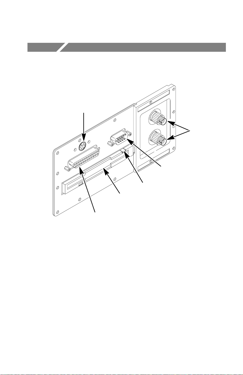
Port Functions
Keyboard connector (on
upgraded instruments and
instruments with serial
numbers B030000 and above)
25-pin parallel port
Laser
output
ports
9-pin RS232C serial port
Disk eject button
Optional 3.5 inch
floppy disk drive
Dust caps and labeling omitted
from illustration
Laser Output Port and Connector Adapter
Laser Output Port
The test fiber connects to the laser output port located on the side
panel. Light is emitted from the laser output port into the test fiber.
If both singlemode and multimode laser output ports are installed,
the singlemode port is in top position and multimode port in bottom
position. If one laser output port is installed, it will always be in the
bottom position. The ports are identified by label.
TFS3031 TekRanger/TekRanger 2 User Manual
1–1
Page 22
Port Functions
CAUTION. Do not fire the laser (push the START/STOP button)
unless a fiber is connected to the laser output port. Severe damage to
internal electronics can result.
Connector Adapter
The connector adapter attaches the fiber to the laser output port.
Connector adapters are packaged separately with new instruments,
and must be installed on the laser output port before use.
The connector adapter on the TFS3031 must match the connector on
the test fiber. See page 5–13 for a list of connector adapter options.
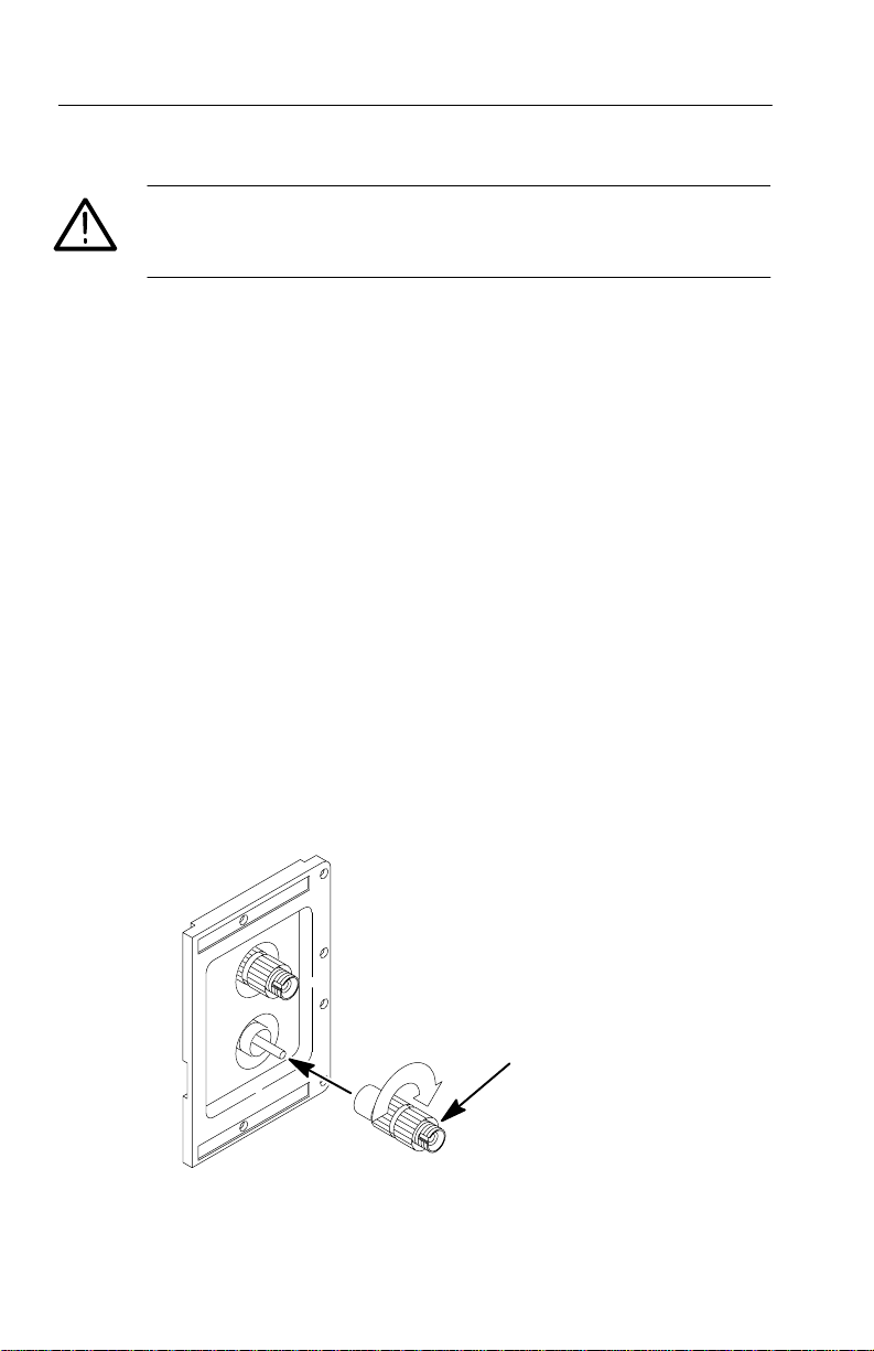
Connector Adapter Installation and Removal
Connector adapters are keyed for proper mating with the laser output
port.
T o install a connector adapter, align the keyed elements, slide the
connector adapter onto the laser output port, and turn clockwise until
the connector adapter is finger tight (see Figure 1–1).
1–2
T o remove a connector adapter, unscrew it counterclockwise and pull
it straight off the port.
Connector
adapter
Figure 1–1: Connector Adapter Installation
TFS3031 TekRanger/TekRanger 2 User Manual
Page 23

CAUTION. Do not touch the exposed end of the laser output port with
anything but the proper cleaning materials. See page 4–1 for
cleaning instructions.
To protect against damage, all ports should be covered with their
dust caps when not in use.
RS232C Serial Port
The 9-pin RS232C serial port connects to an external serial-type
printer or computer. See pages 2–43 and 2–49, and Table 5–4 on
page 5–5, for information about using the serial port.
Parallel Port
The 25-pin parallel port connects to an external parallel-type printer.
See page 2–43 for information about using the parallel port.
Port Functions
Keyboard Connector
A mini-DIN connector is available for an optional keyboard (on
upgraded instruments, and instruments with serial numbers B030000
and above). Refer to section 5 for tables of keyboard sequences that
duplicate front-panel controls and functions.
Floppy Disk Drive
The 1.44 Mbyte, 3.5 inch floppy disk drive for storage of test files is
an optional accessory installed as Option 11. See page 2–29 for file
storage information.
The floppy disk should be removed from the disk drive when not in
use.
TFS3031 TekRanger/TekRanger 2 User Manual
1–3
Page 24

Port Functions
Formatting a Floppy Disk
Both new and used floppy disks may have to be formatted.
Formatting destroys any data already on a disk.
To format a disk:
1. Insert an unformatted disk in the floppy disk drive.
2. Push the Store or Print softkey to access file storage. The
3. To format the disk, push the Yes softkey.
4. Push the Yes softkey again to confirm formatting.
If you insert an unformatted disk while already in file storage, steps
2, 3, and 4 are displayed when you use the Save, Load, Copy, Delete,
or Print file options that involve accessing the floppy disk (when
toggling the Internal/Floppy softkey).
TFS3031 checks the drive for a disk and determines if the disk
can be read. An unformatted disk cannot be read.
If the drive contains an unformatted disk, you are prompted to
format by pushing the Yes softkey , or not to format by pushing
the No softkey.
A final yes/no confirmation prompt is displayed along with a
notice that formatting the disk will destroy any data already on it.
Power/Charger Adapter Port
The power/charger adapter port (2.5 mm DIN), located on
top of the TFS3031, connects to the power/charger
adapter and optional cigarette lighter adapter cable.
The power/charger adapter recharges the NiCad battery
and powers the instrument independent of the battery.
The battery must be charged before first use, and recharged when the
low-battery warning message is displayed on the screen. See page
3–2 for battery recharging instructions.
1–4
TFS3031 TekRanger/TekRanger 2 User Manual
Page 25

Port Functions
CAUTION. Do not connect the power/charger adapter or cigarette
lighter adapter cable to the TFS3031 when the ambient temperature
0
exceeds 40
C (1040 F).
TFS3031 TekRanger/TekRanger 2 User Manual
1–5
Page 26

Port Functions
1–6
TFS3031 TekRanger/TekRanger 2 User Manual
Page 27
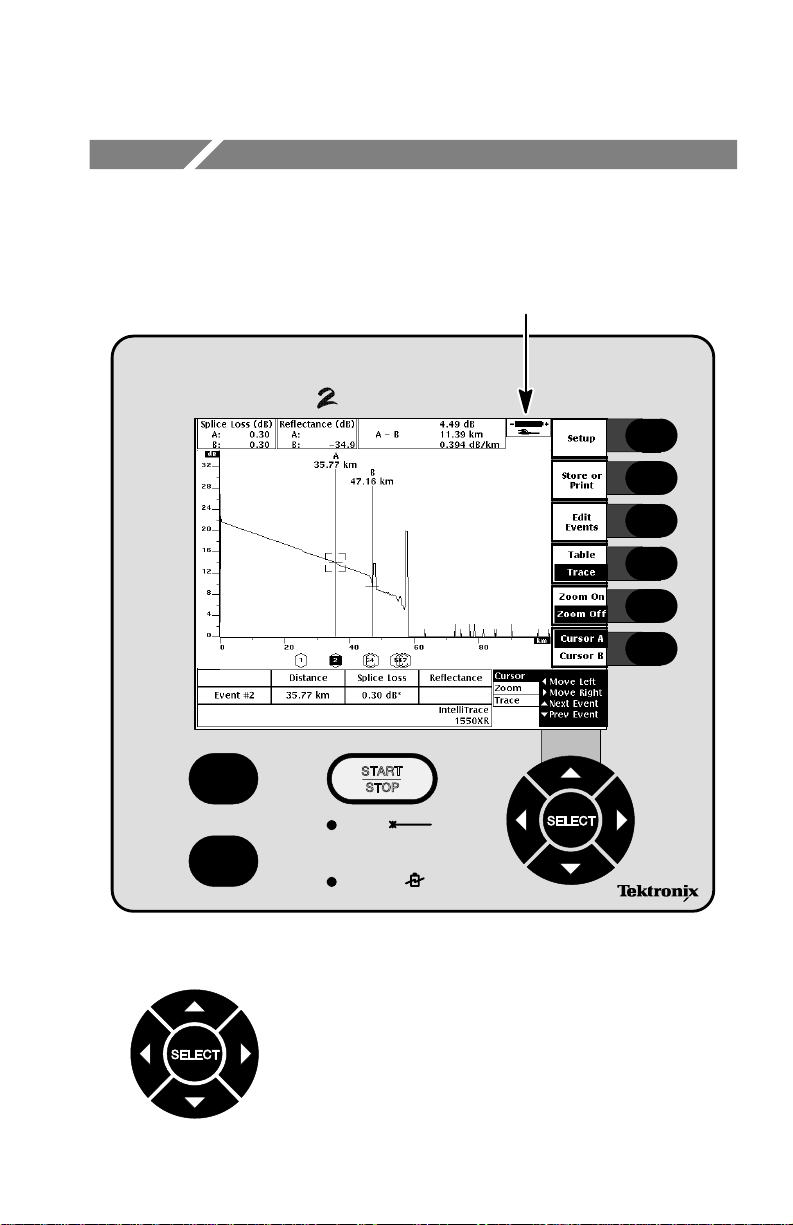
Buttons and Softkeys
HOLD FOR REAL TIME
HELP
Battery indicator. See page 3–1
for battery and power information.
LASER
ON/OFF
BATTERY
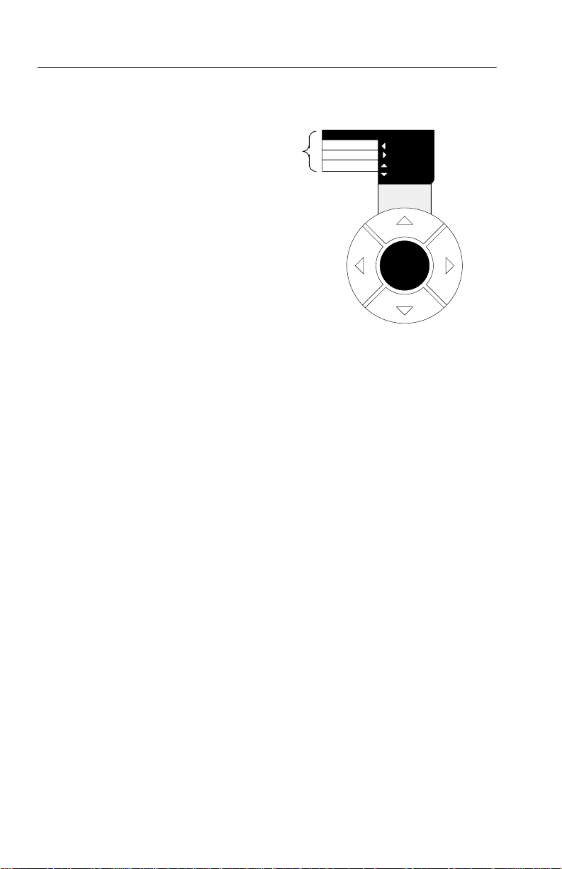
SELECT Button and Arrow Keys
Use the button and arrow keys to move the
cursors, manipulate the waveform, edit events in the
waveform/table display, and select and change
instrument setups.
TFS3031 TekRanger/TekRanger 2 User Manual
1–7
Page 28
Buttons and Softkeys
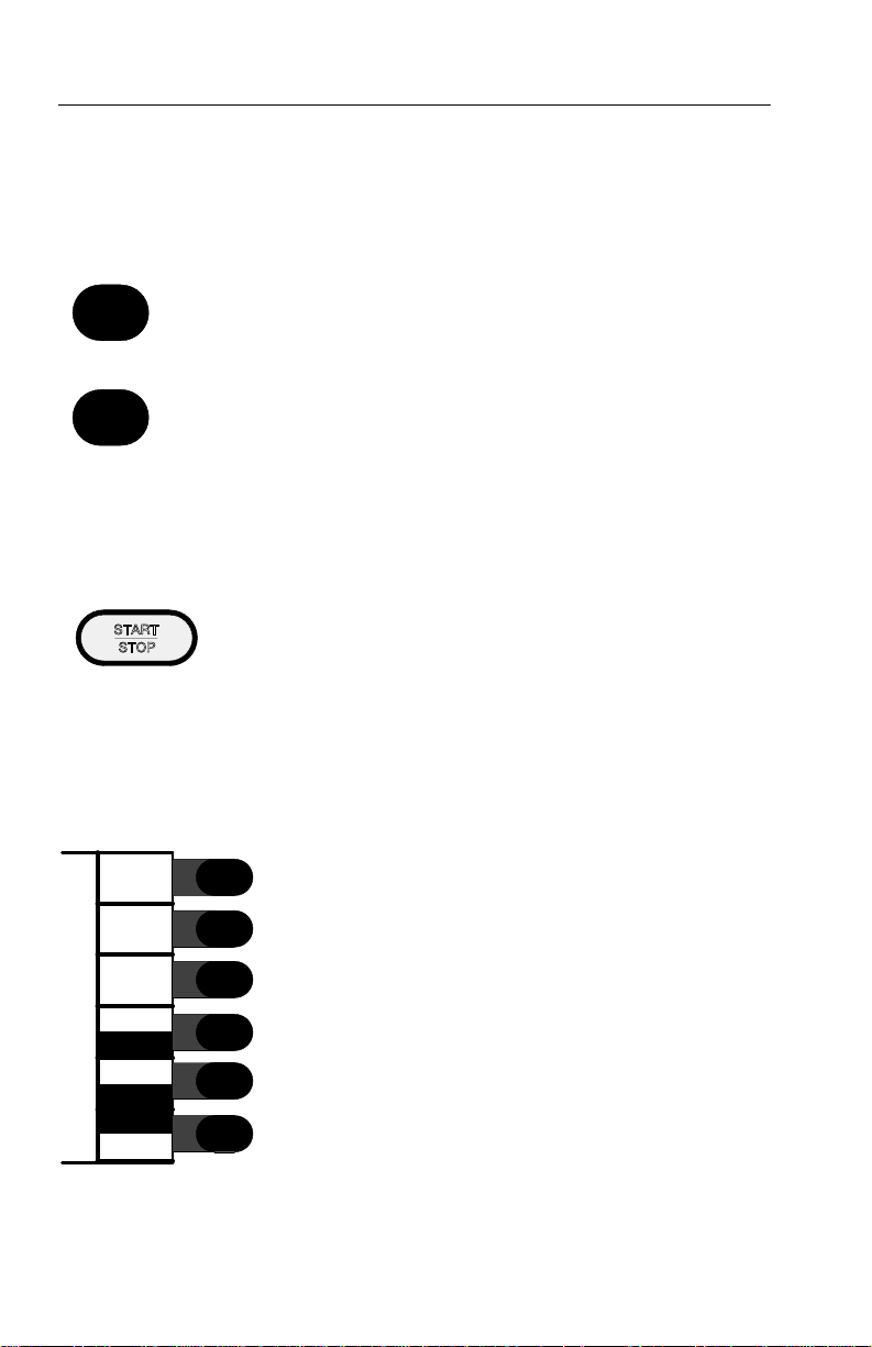
Buttons
ON/OFF
HELP
HOLD FOR REAL TIME
Softkeys
Setup
Store or
Print
Edit
Events
Table
Trace
Zoom On
Zoom Off
Cursor A
Cursor B
The ON/OFF button powers the TFS3031 on and off.
The HELP button provides on-screen descriptive information
about the current instrument function or status.
For information about a button or softkey, push the HELP button,
then push the button or softkey in question.
Push the HELP button again to exit help.
The START/STOP button starts a test and stops a test in
progress. In Manual mode, hold down the START/STOP
button for at least two seconds to begin real-time testing.
Softkeys control the operation of the TFS3031.
Softkeys are displayed along the right side of the
screen next to their pushbuttons. Softkey functions
vary according to the current operating status of the
instrument.
Some softkeys toggle between dual functions, such as
the Cursor A/Cursor B softkey. In dual-function
cases, the currently active function is indicated by
highlighted text. In this illustration, the Trace,
Zoom Off, and Cursor A softkeys are highlighted and
are therefore active.
1–8
TFS3031 TekRanger/TekRanger 2 User Manual
Page 29

Setups
Instrument setups establish the operating parameters of the TFS3031.
Always check and verify setups before testing a fiber. Incorrect
setups can result in inaccurate test results.
The Setup Menus
T o access the setup menus, push the Setup softkey.
The setup menus are:
H Test Setup. Configures the TFS3031 to the specifications of the
fiber under test.
H Format Setup. Selects the type and amount of test data to be
displayed on the screen.
H System Setup. Sets the internal time and date clocks, and
backlight time-out. Adjusts display contrast. Selects instrument
language. Establishes power-on default setups.
H I/O–Doc Setup. Establishes external port, printer, and file setups.
Defines your company name that will be displayed on the
power-on screen and printouts.
Setup menu selections are displayed in the bottom right corner of the
screen (see Figure 1–2 on page 1–10).
Select each setup menu by pushing the SELECT button. Access and
change individual setups by pushing the arrow keys. Setups are in
effect when they are highlighted on the screen.
T o exit setups and resume testing, push the START/STOP button. Or
push the Exit softkey first then the START/STOP button.
TFS3031 TekRanger/TekRanger 2 User Manual
1–9
Page 30
Setups
SELECT button options.
Push SELECT to choose
each setup menu.
Figure 1–2: Setup Menu Options
Test
Format
System
I/O–Doc
Left
Right
Prev Field
Next Field
SELECT
1–10
TFS3031 TekRanger/TekRanger 2 User Manual
Page 31

Setup Summary Tables
Instructions on how to change setups begin on page 1–17.
Setup descriptions begin on page 1–21.
Table 1–1: T est Setup Menu
Setups
Setup
Fiber Scan
(Test Mode)
Test Range Wavelength dependent Fiber Scan dependent
Pulsewidth Wavelength dependent Fiber Scan dependent
Averages 256 to 4,194,304 Fiber Scan dependent
Splice Threshold SM:0.02 to 5.00 dB
Reflectance
Threshold
Scan For All Events,
End of Fiber
Threshold
Refractive Index 1.4000 to 1.6000 1.4680: 1310 SM
Scattering Coefficient
Parameters Factory Default
IntelliTrace
Manual
End of fiber
MM: 0.02 to 5.00 dB
0.01 dB steps
–60.0 dB to –20.0 dB in
5.0 dB steps
Events Above Threshold
3 dB to 10 dB in
1 dB steps
-100 dB to -40 dB -80.3 dB: 1310 SM
IntelliTrace
SM: 0.05 dB
MM: 0.05 dB
–40.0 dB
Events Above Threshold
5 dB
1.4685: 1550 SM
1.4690: 1625 SM
1.4776: 850 MM
1.4719: 1300 MM
-82.3 dB: 1550 SM
-82.8 dB: 1625 SM
-62.3 dB: 850 MM
-69.7 dB: 1300 MM
TFS3031 TekRanger/TekRanger 2 User Manual
1–11
Page 32

Setups
Table 1–1: T est Setup Menu (Cont.)
Setup Factory DefaultParameters
Distance Units Meters
Feet
Miles
Test Port
(Dual-Port Instrument)
Lower
Upper
Meters
Lower
Table 1–2: Format Setup Menu
Setup Parameters Factory Default
Trace Display
Event Event measurement
data at bottom screen
On, Off
Cursor A–B Cursor A to B
measurement data at
top screen On, Off
Splice Loss
(at Cursor A and B)
Reflectance
(at Cursor A and B)
Table Display
Distance Columns 1 – 10, Off Column 1
Loss Columns 1 – 10, Off Column 2
Reflectance Columns 1 – 10, Off Column 3
Slope Columns 1 – 10, Off Column 4
Dead Zone Columns 1 – 10, Off Off
Cumulative Loss Columns 1 – 10, Off Column 5
Loss Tolerance Columns 1 – 10, Off Off
Splice Loss data at top
screen On, Off
Reflectance data at top
screen On, Off
On
On
Off
Off
1–12
TFS3031 TekRanger/TekRanger 2 User Manual
Page 33

Table 1–2: Format Setup Menu (Cont.)
Setup Factory DefaultParameters
Loss Delta
(Between Events)
Distance Tolerance Columns 1 – 10, Off Off
Distance Delta
(Between Events)
Columns 1 – 10, Off
Columns 1 – 10, Off
Setups
Column 6
Column 7
TFS3031 TekRanger/TekRanger 2 User Manual
1–13
Page 34

Setups
Table 1–3: System Setup Menu
Setup
System Setup
Backlight Time Off, 5 minutes to 4
Contrast Adjust 0 (light) to 255 (dark)
Sound On, Off On
Power Off Time Off, 15 minutes to
Time 0:00:00 to 23:59:59 Current time
Date 1/1/1970 to
Date Format Month/Day/Year
Language
(Foreign Language
Instruments)
Keyboard
Translation
Setups at Power On
Power-On Defaults User Setup
Parameters Factory Default
15 minutes
hours in 5-minute
steps, Always On
128
in steps of 1
30 minutes
8 hours in 15-minute
steps
Current date
12/31/2069
Month/Day/Year
Day/Month/Year
English, Spanish,
Portuguese, French,
Standard Chinese,
PRC Chinese, Japanese, German, Italian,
Finnish
USA, French,
German, Spanish,
Portuguese, Italian,
Finnish
Last Used
Factory
English
USA
Last Used
1–14
TFS3031 TekRanger/TekRanger 2 User Manual
Page 35

Table 1–4: I/O–Doc Setup Menu
Setup Parameters Factory Default
RS232C Serial Setup
Baud Rate 1200, 2400, 4800,
9600, 19200,
38400 bps
Flow Control None
XON/XOFF
RTS/CTS
DTR
Printer Setup
Printer Epson
Seiko DPU411
HP DeskJet
HP LaserJet
HP ThinkJet
PostScript
External Port Serial
Parallel
Print Content Trace
Table
Trace and Table
Setups
Fiber Notes
Company Name Up to 24 characters None
File Setup
File Content Trace
Table
Trace and Table
Setups
Fiber Notes
File Format Tektronix
Text
Setups
19200 bps
None
Seiko DPU411
Parallel
Trace and Table
Trace and Table
Tektronix
TFS3031 TekRanger/TekRanger 2 User Manual
1–15
Page 36

Setups
Table 1–4: I/O–Doc Setup Menu (Cont.)
Setup Factory DefaultParameters
File Name Auto
Increment
Fiber ID Auto
Increment
None
Name
Extension
Both
On
Off
Name
On
1–16
TFS3031 TekRanger/TekRanger 2 User Manual
Page 37

Setup Change Procedure
The following exercise shows you how to change setups. The process
is easy: use a combination of the SELECT button and arrow keys.
Setups may be viewed or changed during a test in progress. If the
Fiber Scan, T est Range, Pulsewidth, or Averages setup is changed
during a test in progress, it becomes effective when the next test is
started (push the START/STOP button again). All other setup
changes become effective immediately and influence the current test
in progress.
Setups
Figure 1–3: Typical Setup Screen.
Step 1. To access the setup menus, push the Setup softkey whether
or not there is a test in progress.
A setup menu screen similar to Figure 1–3 is displayed. A
typical setup screen consists of:
TFS3031 TekRanger/TekRanger 2 User Manual
1–17
Page 38

Setups
H A setup field in mid screen that lists all the setups in a
menu. The currently selected setup is highlighted.
H A change bar at bottom screen showing the currently
selected setup parameter and options. An arrow that
indicates more options may show on either end of the
change bar.
NOTE. The setup screen last exited is the same one entered when you
push the Setup softkey.
Step 2. Push the SELECT button repeatedly to cycle through the
setup menus (T est, Format, System, I/O–Doc). SELECT
button options are displayed in the lower right corner of the
screen.
Choose the Test Setup menu to continue with this example.
1–18
Step 3. To cycle through the Test setups, push the
key repeatedly (or hold the key down).
Notice how the setups cycle in the setup field and change
bar.
Choose the Fiber Scan setup to continue. Fiber Scan sets
the test mode of the instrument.
NOTE. In the Test Setup menu, setups enclosed in angle brackets
(< >) are adjusted automatically during the test by the TFS3031 in
order to achieve the best results. These setups are not user selectable.
Step 4. To cycle through the Fiber Scan parameters, push the
or arrow key.
Notice how the parameters cycle in the setup field and
change bar.
TFS3031 TekRanger/TekRanger 2 User Manual
or arrow
Page 39

Setups
Choose the Fiber Scan: IntelliTrace parameter to continue.
IntelliTrace is the most commonly used test mode, and is
used throughout this manual for the various exercises.
Step 5. Continue to use the arrow keys as described in steps 3 and 4
to change other setups in the T est Setup menu as needed for
your application.
NOTE. If two Laser Output ports are installed in the instrument, make
sure that the proper port is selected in the Test Port setup.
If you make a mistake in any menu, use the arrow keys to reselect
and correct your mistake, or push the Undo softkey before going to
the next setup.
Step 6. Push the SELECT button to choose the other setup menus
(Format, System, and I/O–Doc).
Use the arrow keys as described in steps 3 and 4 to change
setups in these menus as needed for your application.
Step 7. When you are through changing setups:
Push the START/STOP button to immediately begin a test
using your new setups (or first push the Exit softkey, then
the START/STOP button).
–or–
Before exiting setups, save your new setups as the next
power-on defaults:
1. Push the SELECT button to choose the System menu.
2. Push the
3. Push the arrow key to select Last Used.
See page 1–40 for information about other default options.
Only setups established as defaults continue in effect after
power off, and battery discharge or removal.
TFS3031 TekRanger/TekRanger 2 User Manual
arrow key to choose Power-On Defaults.
1–19
Page 40

Setups
Example Setup Sequences
The following example shows a typical sequence of buttons and keys
used to (1) view the setup menus; and (2) change a setup and
establish it as a default (the setup is Splice Threshold in the Test
menu).
(1) To view the setup menus:
push Setup softkey
push SELECT button (choose Format menu)
push SELECT button (choose System menu)
push SELECT button (choose I/O–Doc menu)
push SELECT button (choose Test menu)
push Exit softkey
(2) To change a setup and establish it as the default:
push Setup softkey
push SELECT button (choose Test menu)
push key (choose Splice Threshold setup)
push key (choose 0.50 dB parameter)
push SELECT button (choose System menu)
push key (choose Power-On Defaults setup)
push key (choose Last Used)
push Exit softkey
1–20
TFS3031 TekRanger/TekRanger 2 User Manual
Page 41

Setup Definitions
Test Setup Menu
The Test Setup menu configures the TFS3031 to the specifications of
the fiber under test.
Setups
Figure 1–4: Typical Test Setup Menu Screen.
TFS3031 TekRanger/TekRanger 2 User Manual
1–21
Page 42

Setups
Fiber Scan
The Fiber scan setup specifies the test mode of the instrument. Fiber
Scan selections are: IntelliTrace Manual, and End of Fiber.
H IntelliTrace. IntelliTrace mode automatically locates and
measures all events on a fiber. It is the easiest and most
commonly used test mode, and is the factory default.
IntelliTrace is a single-button test that automatically adjusts the
test setups to provide the best possible resolution for measuring
close-in events, while maintaining the necessary dynamic range
for measuring distant events. The result is a more accurate
waveform, and an event table that contains more accurate
measurements.
IntelliTrace mode automatically adjusts the Test Range,
Pulsewidth, and A verages parameters during the test. All other
parameters are user settable.
H Manual. Use Manual mode when testing with specific Test
Range, Pulsewidth, and A verages parameters, and when doing
real-time and high-density testing.
1–22
The Splice Threshold, Reflectance Threshold, Scan For, and End
of Fiber Threshold setups are disabled. All other parameters are
user settable.
H End of Fiber. End of Fiber mode quickly locates the end of the
fiber, and measures total length, slope, and loss. It does not locate
or measure other events.
The Test Range, Pulsewidth, and Averages parameters are
adjusted automatically. The Splice Threshold, Reflectance
Threshold, and Scan For setups are disabled. All other parameters
are user settable.
TFS3031 TekRanger/TekRanger 2 User Manual
Page 43

Setups
Test Range
T est Range specifies the maximum fiber distance over which test
data is acquired. T o avoid ghosting, the test range should be set to a
little longer than the full length of the fiber.
T est Range depends upon laser wavelength selected. When switching
between laser wavelengths (on dual-wavelength instruments), the
T est Range parameter automatically changes to accommodate the
laser currently selected.
T est Range and Pulsewidth setups are interdependent. Pulsewidth
parameters are displayed with the T est Range parameters. If you
change the test range, and the current pulsewidth is incompatible, the
closest compatible pulsewidth is automatically selected.
T est Range selections depend on the wavelength. Factory default
depends on the Fiber Scan setup and the wavelength selected.
Factory default is Auto in IntelliTrace and End of Fiber modes. In
Manual mode, factory default is 4 km for 850 nm multimode, 8 km
for 1300 nm multimode, and 20 km for all other wavelengths.
Pulsewidth
Pulsewidth specifies the length of time the laser is on during each
sampling acquisition, measured in distance units. A sampling
acquisition is the acquisition of one complete set of data points on a
waveform.
Short pulsewidths permit more detail but have limited range. Long
pulsewidths permit longer range but provide less detail.
Certain pulsewidths are not available on some wavelengths. When
switching between laser wavelengths (on multi-wavelength
instruments), the Pulsewidth parameter may change.
TFS3031 TekRanger/TekRanger 2 User Manual
1–23
Page 44

Setups
Pulsewidth and T est Range setups are interdependent. Test Range
parameters are displayed with the Pulsewidth parameters. If you
change the pulsewidth, and the current test range is incompatible, the
closest compatible test range is automatically selected.
Factory default depends on the Fiber Scan setup and the wavelength
selected. Factory default is Auto in IntelliTrace and End of Fiber
modes. In Manual mode, factory default is 10 m for 850 and 1300
nm multimode, and 20 m for all other wavelengths.
Averages
Averages specifies the number of averages required by a test based
upon the currently selected pulsewidth and test range.
Increase averages to reduce noise and increase range. An estimate of
the time necessary to take the selected number of averages is
displayed on the screen.
Selections are 256 to 4,194,304. Factory default depends on the Fiber
Scan setup.
Averages is set automatically in IntelliTrace and End of Fiber modes,
and is user settable in Manual mode.
1–24
TFS3031 TekRanger/TekRanger 2 User Manual
Page 45

Setups
Splice Threshold
Splice Threshold specifies the threshold level (in dB) used in
marking splices. Splice events that have a loss equal to or greater
than the threshold are indicated with an asterisk (*).
Selections are 0.02 to 5.00 dB for both singlemode and multimode,
in 0.01 dB steps. Factory defaults are 0.05 dB for both singlemode
and multimode.
When the Scan For setup is set to Events Above Threshold, lowering
the splice threshold can cause new events to be marked, and
increasing the threshold can cause events to be deleted.
Splice Threshold is user settable in IntelliTrace mode, and is disabled
in Manual and End of Fiber modes.
Reflectance Threshold
Reflectance Threshold specifies the threshold level (in dB) for
marking reflective events. Reflections equal to or greater than
threshold are indicated with an asterisk (*).
Selections are –60.0 dB to –20.0 dB in 5.0 dB steps. Factory default
is –40.0 dB.
When the Scan For setup is set to Events Above Threshold, lowering
the reflectance threshold can cause new events to be marked, and
increasing the threshold can cause events to be deleted.
Reflectance Threshold is user settable in IntelliTrace mode, and is
disabled in Manual and End of Fiber modes.
TFS3031 TekRanger/TekRanger 2 User Manual
1–25
Page 46

Setups
Scan For
Scan For specifies whether to display all events or only events equal
to or greater than the user-set splice and reflectance threshold levels.
Only those events that are scanned for are displayed on the screen.
An asterisk (*) marks the splice loss or reflectance measurements
that are equal to or greater than the threshold.
Selections are All Events or Events Above Threshold. Factory
default is Events Above Threshold.
Scan For is user settable in IntelliTrace mode, and is disabled in
Manual and End of Fiber modes.
End of Fiber Threshold
End of Fiber Threshold specifies the threshold level (in dB) for
detecting the end of the fiber. The first event that has a loss equal to
or greater than the threshold level is marked as the end of the fiber,
then the test stops.
Selections are 3 dB to 10 dB in 1 dB steps. Factory default is 5 dB.
1–26
End of Fiber Threshold is user settable in IntelliTrace and End of
Fiber modes, and is disabled in Manual mode.
TFS3031 TekRanger/TekRanger 2 User Manual
Page 47

Setups
Refractive Index
Refractive index is the ratio between the speed of light in a vacuum
to speed of light in a fiber.
Refractive index varies from fiber to fiber and is an important setup
for achieving accurate test results. A change in the refractive index
affects the distance scale on the screen and fiber measurements.
The refractive index is usually available from the fiber manufacturer.
Refer to T able1–1 on page 1–11 for factory default settings.
Refractive Index is user settable in all modes.
If the refractive index of a fiber is unknown, you can calibrate the
index using a known length of fiber, or a fiber containing a segment
of known length, as follows:
1. T est the fiber and display the waveform.
2. Position Cursor A on the first point on the leading edge of the
event at the start of the fiber segment. Position Cursor B on the
leading edge of the event at the end of the segment.
For precise cursor positioning, zoom the waveform (see page
2–15 for instructions on moving the cursors and page 2–19 for
information about zooming).
3. Access the Refractive Index setup in the Test menu.
4. Use the arrow keys to change the Refractive Index parameter. As
the parameter changes, the distance scale readjusts, changing the
distance to the cursors. When the A–B distance on the T est Setup
menu matches the known length of the fiber segment, the
Refractive Index setup is correct.
TFS3031 TekRanger/TekRanger 2 User Manual
1–27
Page 48

Setups
Scattering Coefficient
The scattering coefficient represents the amount of backscatter
reflected by a particular fiber. The scattering coefficient is not
required, but if you know the coefficient of your test fiber, you can
use it to maximize reflectance-measurement accuracy. The scattering
coefficient is a characteristic of the fiber under test and, similar to
the refractive index, can vary from fiber to fiber.
The scattering coefficient is usually available from the fiber
manufacturer. If you do not know the scattering coefficient, however,
use the factory-default values.
NOTE. The scattering coefficient applies only to reflectance
measurements and has no effect on any other types of measurements.
When comparing a reflectance measurement to any previous
reflectance measurements made on the same event, be sure to use the
same scattering coefficient that was used for the previous measurement.
Refer to T able1–1 on page 1–11 for factory default settings.
1–28
For 1550-nm dispersion-shifted fiber, use a scattering coefficient of
-78.2.
If you do not know the scattering coefficient of a particular fiber, but
the fiber includes a reflection with a known reflectance, adjust the
scattering coefficient until the reflectance value for the event is
correct.
When you change the scattering coefficient, reflectance values are
not automatically recalculated. T o recalculate reflectance values,
retest the fiber.
The scattering coefficient is user settable in all modes.
TFS3031 TekRanger/TekRanger 2 User Manual
Page 49

Setups
Distance Units
Distance Units specifies measurements to be displayed on the screen
in meters, feet, or miles. Factory default is meters.
Distance is displayed on the horizontal scale under the waveform,
numerically at the top of each cursor, and in the event table columns.
Distance Units is user settable in all modes.
Test Port
T est Port specifies which Laser Output port option to use if two ports
(upper and lower) are installed.
Selections are Lower or Upper port. Factory default is Lower port.
T est Port is user settable in all modes.
This setup is not displayed if your instrument contains only one port.
TFS3031 TekRanger/TekRanger 2 User Manual
1–29
Page 50

Setups
Format Setup Menu
The Format Setup menu selects the categories of test data to be
included on the waveform and event table screens. It lets you
customize the screen for your particular needs.
1–30
Figure 1–5: Format Setup Menu Screen.
TFS3031 TekRanger/TekRanger 2 User Manual
Page 51

Setups
TRACE DISPLAY Setups
Trace display setups turn on and off data included on the waveform
screen.
Event
In the waveform display, Event turns display of measurement data
for the event closest to the currently active cursor on and off. Event
data is displayed at bottom screen.
Selections are On or Off. Factory default is On.
Cursor A–B
In the waveform display, Cursor A–B turns display of the difference
in measurement data between the cursors on and off. Measurement
data includes loss in dB, distance, and loss/distance. Cursor A–B
data is displayed at top screen.
Selections are On or Off. Factory default is On.
Splice Loss
In the waveform display, Splice Loss turns display of the splice loss
measurement at each cursor on and off. Moving a cursor causes the
TFS3031 to recalculate the splice loss at the new cursor location.
Cursor A and B splice loss data is displayed at top screen.
Selections are On or Off. Factory default is Off.
Reflectance
In the waveform display, Reflectance turns display of the reflectance
measurement at each cursor on and off. Moving a cursor causes the
TFS3031 to recalculate the reflectance at the new cursor location (if
a reflection exists). Cursor A and B reflectance data is displayed at
top screen.
Selections are On or Off. Factory default is Off.
TFS3031 TekRanger/TekRanger 2 User Manual
1–31
Page 52

Setups
T ABLE DISPLAY Setups
T able display setups change the order of (or turn off) the columns of
data in the event table. Changing the order of a column causes the
remaining column numbers to reorder.
Measurements that are turned off will not appear in the table or
printouts. However, they are saved when saving a file in storage so
that they can be accessed when the file is loaded back onto the
screen.
Distance
Distance is the distance to each event from the TFS3031 front panel.
In the event table display, Distance specifies the position of the
Distance data column relative to the other columns in the table, or
turns the Distance column off.
Selections are columns 1 through 10; Off. Factory default is
column 1.
1–32
Loss
Loss is the loss of optical power due to scattering, absorption, and
bending.
In the event table display, Loss specifies the position of the Loss data
column relative to the other columns in the table, or turns the Loss
column off.
Selections are columns 1 through 10; Off. Factory default is
column 2.
TFS3031 TekRanger/TekRanger 2 User Manual
Page 53

Setups
Reflectance
Reflectance is the ratio of reflected optical power to incident optical
power for reflective events.
In the event table display, Reflectance specifies the position of the
Reflectance data column relative to the other columns in the table, or
turns the Reflectance column off.
Selections are columns 1 through 10; Off. Factory default is
column 3.
Slope
Slope is attenuation of the fiber between an event and the preceding
event.
In the event table display, Slope specifies the position of the Slope
data column relative to the other columns in the table, or turns the
Slope column off.
Selections are columns 1 through 10; Off. Factory default is
column 4.
Dead Zone
Dead zone is the distance from the beginning of an event to the point
at which backscatter is detected, and subsequent events can be
accurately detected and measured.
In the event table display, Dead Zone specifies the position of the
Dead Zone data column relative to the other columns in the table, or
turns the Dead Zone column off.
Selections are columns 1 through 10; Off. Factory default is off.
TFS3031 TekRanger/TekRanger 2 User Manual
1–33
Page 54

Setups
Cumulative Loss
Cumulative loss is the total loss from the TFS3031 front panel to
each event.
In the event table display, Cumulative Loss specifies the position of
the Cumulative Loss data column relative to the other columns in the
table, or turns the Cumulative Loss column off.
Selections are columns 1 through 10; Off. Factory default is
column 5.
Loss Tolerance
Loss tolerance is the repeatability of the splice loss at each event.
In the event table display, Loss Tolerance specifies the position of
the Loss T olerance data column relative to the other columns in the
table, or turns the Loss T olerance column off.
Selections are columns 1 through 10; Off. Factory default is off.
Loss Delta (Between Events)
1–34
Loss delta is the loss between an event and the preceding event.
In the event table display, Loss Delta specifies the position of the
Loss Delta data column relative to the other columns in the table, or
turns the Loss Delta column off. The data is for events marked by
cursor A and cursor B.
Selections are columns 1 through 10; Off. Factory default is
column 6.
TFS3031 TekRanger/TekRanger 2 User Manual
Page 55

Setups
Distance Tolerance
Distance tolerance is the repeatability of the distance measurement at
each event.
In the event table display, Distance Tolerance specifies the position
of the Distance T olerance data column relative to the other columns
in the table, or turns the Distance T olerance column off.
Selections are columns 1 through 10; Off. Factory default is off.
Distance Delta (Between Events)
Distance delta is the distance between an event and the preceding
event.
In the event table display, Distance Delta specifies the position of the
Distance Delta data column relative to the other columns in the table,
or turns the Distance Delta column off. The data is for events marked
by cursor A and cursor B.
Selections are columns 1 through 10; Off. Factory default is
column 7.
TFS3031 TekRanger/TekRanger 2 User Manual
1–35
Page 56

Setups
System Setup Menu
The System Setup menu:
H Sets the internal time and date clocks.
H Sets backlight timing.
H Adjusts display contrast.
H Selects language.
H Establishes power-on default setups.
1–36
Figure 1–6: System Setup Menu Screen.
TFS3031 TekRanger/TekRanger 2 User Manual
Page 57

Setups
SYSTEM SETUP
System setups set and adjust screen contrast, and system date and
time features, and instrument language features.
Backlight Time
Backlight Time specifies the amount of time before the backlight
blanks to save battery power when button and softkey activity is
suspended. The backlight will not blank when the power/charger
adapter is plugged in, or when a test is in progress.
Selections are backlight Off, 5 minutes to 4 hours in 5 minute steps,
and backlight Always On. Factory default is 15 minutes.
Push any button or softkey to reactivate the backlight after blanking.
Contrast Adjust
Contrast Adjust adjusts the contrast level of the screen for optimum
viewing. Selections are 0 (light) to 255 (dark) in steps of 1. Factory
default is 128 (average contrast). The TFS3031 always powers up
with the same constrast setting that was last used.
T o adjust screen contrast, push the
or the
adjusted at initial power on after pushing the button, and
before pushing any other buttons or keys.
Sound
Sound provides an audible beep when a test is complete, and when
you push an inactive button or softkey.
Selections are On or Off. Factory default is On.
TFS3031 TekRanger/TekRanger 2 User Manual
arrow key to increase contrast. Contrast can also be
arrow key to decrease contrast,
1–37
Page 58

Setups
Power Off Time
Power Off Time specifies the amount of time before the TFS3031
powers itself off automatically to save battery power in the event of
suspended activity. The instrument will not time-out when connected
to external power, or when a test is in progress.
Selections are Off (disabled) or 15 minutes to 8 hours in 15 minute
steps. Factory default is 30 minutes.
To resume activity after power off, push the button to
power the TFS3031 back on.
Time
Time sets the internal time clock to hours:minutes:seconds. Time is
used to time-stamp stored, printed, and copied data.
Date
Date sets the internal date clock. The clock is formatted to either
month/day/year or day/month/year (depending on Date Format
setup). Date is used to date-stamp stored, printed, and copied data.
1–38
Date Format
Date Format formats the date display to either month/day/year or
day/month/year.
Factory default is month/day/year.
TFS3031 TekRanger/TekRanger 2 User Manual
Page 59

Setups
Language
Language establishes the display text language. In addition to
English, the TFS3031 may contain any one of the following
languages: Spanish, Portuguese, French, standard Chinese, PRC
Chinese, German, Japanese, Italian, and Finnish.
Factory default is English.
This setup is displayed only on instruments that have the foreign
language options.
When the Power On Defaults parameter is set to Factory, the
instrument powers up in the language last used.
Keyboard T ranslation
Keyboard Translation sets the language used by the keyboard. The
selections are USA, French, German, Spanish, Portuguese, Italian,
and Finnish. This parameter allows you to set the TFS3031 to
recognize a localized keyboard for any of these languages.
If you do not use a localized keyboard when a foreign language is
selected for the keyboard translation, the keyboard produces the
foreign-language characters regardless of the keycap labels.
Factory default is USA.
When the Power On Defaults parameter is set to Factory, the
keyboard powers up in the translation setting last used.
TFS3031 TekRanger/TekRanger 2 User Manual
1–39
Page 60

Setups
SETUPS A T POWER ON
Power-on setups determine the setups that will be in effect at the next
and future power ons.
Power-On Defaults
Power-On Defaults establishes the setups that will be in effect in the
future. Default setups remain in effect when the TFS3031 is powered
off, and when the battery is discharged or removed.
T o establish defaults, first select your setups. Then, before powering
off the TFS3031:
1. Push the SELECT button to choose the System menu.
2. Push the
H To save the setups that are in effect when the TFS3031 is
powered off as defaults at next power on, push the arrow
key to select Last Used.
H T o permanently save your own ‘‘personal profile’’ set of
setups for future recall (but not necessarily at next power on),
push the
Save Latest User Setup softkey.
Your personal profile setups are now saved permanently. In
the future you can recall your personal profile setups by
selecting User Setup before powering off the instrument, and
they will be the default at next power on.
H T o revert to original factory setups as defaults at next power
on, push the
NOTE. For instruments that contain foreign-language options: when
the Power On Defaults are set to Factory, the TFS3031 powers up in
the language and keyboard translation that were last selected. Note
that these setups work the same way for both the Last Used and the
Factory settings of the Power On defauts parameter.
arrow key to choose the Power-On Defaults setup.
arrow key to select User Setup. Then push the
arrow key to select Factory.
1–40
TFS3031 TekRanger/TekRanger 2 User Manual
Page 61

Setups
I/O–Doc Setup Menu
The I/O–Doc Setup menu establishes RS232C serial, printer, and file
setups, and defines your company name to be included with file data.
Figure 1–7: Typical I/O–Doc Setup Menu Screen.
TFS3031 TekRanger/TekRanger 2 User Manual
1–41
Page 62

Setups
RS232 SERIAL SETUP
Serial setups set the baud rate and flow control used when downloading files to a personal computer or printer.
Baud Rate
Baud Rate specifies the RS232C serial port data output rate when
copying files to a personal computer or using an RS232 printer.
Selections are 1200, 2400, 4800, 9600, 19200, or 38400 bps. Factory
default is 19200 bps.
Flow Control
Flow Control specifies the RS232C serial port data flow control
when copying files to a personal computer or using an RS232 printer.
If connected to a computer, Flow Control cannot be set to XON/
XOFF.
Selections are None, XON/XOFF, RTS/CTS, or DTR. Factory
default is None.
1–42
PRINTER SETUP
Printer setups are setups that affect an external printer.
Printer
Printer specifies the type of external printer used to print files.
Selections are Seiko DPU411, Epson, HP DeskJet, HP LaserJet, HP
ThinkJet, and PostScript. Factory default is Seiko DPU411.
Although printers can be connected to the serial port, we recommend
using the parallel port. If using the serial port, see T able 5–4 on page
5–5 for information about serial cables and printer setups.
TFS3031 TekRanger/TekRanger 2 User Manual
Page 63

Setups
External Port
External Port specifies the communications port (located on the side
panel) that connects the TFS3031 to the printer or personal computer.
If connected to a computer, set External Port to Serial.
Selections are Serial or Parallel port. Factory default is Parallel port.
Print Content
Print Content specifies the type of test data to be printed. The
selections are:
H Trace–prints waveform, instrument setups, fiber notes, and event
notes.
H Table–prints event table, event notes, fiber notes, and instrument
setups.
H Trace and Table–prints waveform, instrument setups, fiber
notes, event table, and event notes.
H Setups–prints instrument setups only .
H Fiber Notes–prints fiber notes only.
Factory default is Trace and Table.
Company Name
Company Name includes the name of your company (or other
identifying text) as part of the power-on screen and on printouts. Up
to 24 characters can be included using the editing procedure accessed
by pushing the Edit Company Name softkey. Factory default is no
name.
TFS3031 TekRanger/TekRanger 2 User Manual
1–43
Page 64

Setups
FILE SETUP
File setups determine the content, formatting, and incrementation of
test files.
File Content
File Content determines the content of the file to be stored in
memory . Selections are:
H Trace–saves waveform data, instrument setups, and fiber notes.
H Table–saves the event table, instrument setups, fiber notes, and
event notes.
H Trace and Table–saves waveform data, event table, instrument
setups, fiber notes, and event notes.
H Setups–saves instrument setups and fiber notes.
H Fiber Notes–saves fiber notes only.
Factory default is Trace and Table.
1–44
File Format
File Format formats file output in either ASCII (T ext) or Tektronix
common file format.
Use T ektronix common file format:
H For storing waveforms.
H When files will be read by other T ektronix OTDRs.
H When using FMTAP, Tektronix’ Microsoft Windows based
trace analysis software package.
H When copying files to a personal computer.
H When files will be loaded back onto the screen for viewing.
TFS3031 TekRanger/TekRanger 2 User Manual
Page 65

Setups
Use T ext format only when transferring waveform or event-table data
to a spreadsheet.
NOTE. Waveform and event-table files that have been saved in Text
format cannot be loaded back onto the screen or used with FMTAP.
When you save files in Text format, make sure you have backup
copies to preserve the waveform data.
You can reload a fiber-notes-only file that has been saved using Text
format. This allows you to edit fiber notes on a PC or workstation,
then reload them into the TFS3031. Fiber notes are formatted in the
following format:
title;description
Title is a field up to 23 characters in length. Description is a field up
to 55 characters in length. The title and description fields are
separated by a semicolon. The fiber-notes file can contain up to 15 of
these notes.
If you edit file notes in a T ext-format file, be sure to edit only the
lines of note text. Leave the rest of the file unchanged in order to
ensure that it will reload properly on the TFS3031.
Factory default is T ektronix common file format.
File Name Auto Increment
File Name Auto Increment specifies how file names are automatically incremented when files are saved.
Selections are None (disabled), Name, Extension, or Both (name and
extension). Factory default is Name.
Examples:
Name: FILE0001.CFF increments to FILE0002.CFF
FILE_A.CFF increments to FILE_B.CFF
Extension: FILE.001 increments to FILE.002
FILE.AAA increments to FILE.AAB
Both: FILE0018.999 increments to FILE0019.000
FILE00A.ABC increments to FILE00B.ABD
TFS3031 TekRanger/TekRanger 2 User Manual
1–45
Page 66

Setups
Fiber ID Auto Increment
Fiber ID Auto Increment specifies whether fiber IDs are automatically incremented when files are saved.
Selections are On and Off. Factory default is Off.
Examples:
FIBER0001 increments to FIBER0002
FIBERAAA increments to FIBERAAB
1–46
TFS3031 TekRanger/TekRanger 2 User Manual
Page 67

Testing a Fiber
In Section 2 you learn how to:
H T est a fiber and make fiber measurements.
H Add and delete user-placed events.
H Add and edit fiber notes and event notes.
H Store files in memory and on floppy disk.
H Print files on an external printer.
H Copy files to a personal computer.
Section 2.
Page 68

Page 69

Testing a Fiber
This section provides exercises and examples on how to test a fiber
and make fiber measurements. The procedures apply to all
instrument options, both singlemode and multimode.
For simplicity, these exercises use Fiber Scan: IntelliTrace mode, the
most commonly used mode for testing a fiber.
We suggest that you use IntelliTrace mode to become familiar with
how the TFS3031 works. Then use the other modes (Manual and End
of Fiber) as needed.
Note that when you exit a test in progress to go to another process,
the test continues. T o start a test over, push the START/STOP
button.
WARNING. INVISIBLE LASER RADIATION. To eliminate hazardous
radiation exposure do not use controls or adjustments or perform
procedures other than those specified in this manual.
Avoid eye exposure to laser output and open-ended fibers by
covering the end or directing the output at a nonreflective surface.
CAUTION. Do not fire the laser (push the START/STOP button)
unless a fiber is connected to the Laser Output port. Severe damage
to internal electronics can result.
NOTE. Before using the TFS3031, recharge the NiCad battery to
capacity, and clean the Laser Output port and fiber connectors.
H See page 3–2 for NiCad battery recharging instructions.
H See page 4–1 for optical cleaning instructions.
TFS3031 TekRanger/TekRanger 2 User Manual
2–1
Page 70

Testing A Fiber
2–2
Figure 2–1: Typical IntelliTrace T est Screens: Waveform (Top) and Event
Table (Bottom). Seven Events are Detected. Event 2 is Selected.
TFS3031 TekRanger/TekRanger 2 User Manual
Page 71

Fiber Test Procedure
The following example describes how to test and make measurements on a fiber. This example is typical of a new first-time test after
instrument power on.
Step 1. Connect the test fiber to the connector adapter on the
appropriate Laser Output port (on dual-port instruments).
Connect the fiber directly to the port or use a jumper cable.
The connection should be finger tight.
The connector adapter and fiber connector must match. If
necessary, see page 1–2 for connector adapter installation
instructions.
Testing A Fiber
Note: If both singlemode and multimode Laser Output ports
are installed, singlemode will be on top and multimode on
bottom. If one Laser Output port is installed, it will always be
on the bottom whether singlemode or multimode. The ports
are identified by label.
TFS3031 TekRanger/TekRanger 2 User Manual
2–3
Page 72

T esting A Fiber
Step 2. Push the ON/OFF button to power on the TFS3031.
Wait a moment. The instrument goes through a power-on
self test sequence, and displays the following ‘ ‘ready’’
screen after successful power on.
Note that screen contrast can be adjusted now.
2–4
If the TFS3031 displays an error message during power on,
see page 4–1 for cleaning and troubleshooting instructions.
Step 3. ( OPTIONAL ). Check your setups to make sure that the
TFS3031 is configured properly for the test.
Push the Setup softkey . Then push the SELECT button to
view the setup menus. If necessary , see page 1–9 for
information about reviewing and changing setups.
H If two Laser Output ports are installed, make sure that
the proper port is selected using the Test Port setup in the
Test Setup menu.
TFS3031 TekRanger/TekRanger 2 User Manual
Page 73

T esting A Fiber
H If a dual-wavelength port is installed, make sure the
proper wavelength is selected as indicated by the
‘‘wavelength’’ softkey (third softkey down on the front
panel when the Test Setup menu is displayed).
H For the purpose of this exercise, make sure that the
Fiber Scan: IntelliTrace setup is selected in the Test
Setup menu. IntelliTrace allows full automatic testing.
Step 4. Push the button to exit setups and begin
testing the fiber.
Wait a moment. The flashing red LASER LED on the front
panel indicates that the test is in progress. The screen also
displays an elapsed time for the test.
To stop a test in progress anytime, push the
button.
Step 5. When the test is complete, results are displayed on the
screen as either a waveform or event table (see Figure 2–1
on page 2–2, and the waveform/event table descriptions on
pages 2–8 and 2–11).
Push the / softkey to toggle between the
waveform and event table screens. Notice the difference in
display formats for the same test.
T o continue with this exercise, display the waveform screen.
Step 6. Bring both cursors into view on the waveform.
The cursors, labeled A and B, are used for making fiber
measurements.
When a waveform is first acquired, the cursors are at the
zero distance point on the waveform (left side of the
screen). They are hard to see except for their distance
indicators that show 0.0 distance.
T o bring the cursors into view for making measurements:
TFS3031 TekRanger/TekRanger 2 User Manual
2–5
Page 74

T esting A Fiber
1. Push the SELECT button to choose the Cursor option (as
highlighted in lower right screen – see Figure 2–2 on
page 2–8). The Cursor option enables the arrow keys
for cursor movement.
For this exercise, assume that cursor A is the active
cursor (Cursor A softkey highlighted).
2. Hold down either the
along the waveform, or the arrow key to jump cursor
A from event to event, until cursor A is positioned on the
first point on the leading edge of the first event to be
measured.
To see the most detail in an event, and for the most
precise cursor placement, zoom the waveform. See page
2–19 for information about waveform zooming.
3. Push the Cursor B softkey to switch the active cursor to
cursor B.
4. Repeat step 2 to position cursor B on the first point on
the leading edge of the second event to be measured.
Step 7. You now have a complete fiber test showing a complete set
of measurements at both cursor locations.
Again, push the Table/Trace softkey to toggle between the
waveform and event table screens. Notice the difference
between how measurement results are displayed.
Step 8. Continue with the rest of this section to learn more about:
H Contents of the waveform screen (page 2–8).
arrow key to scroll cursor A
2–6
H Contents of the event table screen (page 2–11).
H Using the cursors (page 2–15).
H Using the SELECT button and arrow keys (page 2–17).
H Zooming the waveform (page 2–19).
H Real-time and high-density testing (page 2–21).
TFS3031 TekRanger/TekRanger 2 User Manual
Page 75

T esting A Fiber
H Adding and deleting user-placed events (page 2–23).
H Including notes and comments with events (page 2–26).
H Storing files in memory and editing file names (page
2–29).
H Printing files (page 2–43).
H Copying files to a personal computer (page 2–49).
TFS3031 TekRanger/TekRanger 2 User Manual
2–7
Page 76

T esting A Fiber
The Waveform Defined
2–8
Figure 2–2: Typical Waveform Screen. Event 2 is Selected.
The waveform screen displays an analog representation of
the entire tested length of the fiber.
H The scale on the left side of the waveform displays loss
in dB units. The scale below the waveform displays
distance in meters, feet, or miles.
H Numbered event markers located under the distance
scale (
the currently selected event is highlighted. Each event
marker corresponds to a numbered event listed in the
event table.
In Figure 2–2, seven events are detected. Event number
two is currently selected.
) pinpoint each event detected. The marker for
TFS3031 TekRanger/TekRanger 2 User Manual
Page 77

T esting A Fiber
H A
H Information boxes at top and bottom screen display
H Distance measurements from the front panel to the
H The Setup softkey accesses the setup menus.
H The Store or Print softkey accesses menus for storing,
symbol located under the distance scale indicates a
user-placed event. (There are no user-placed events in
Figure 2–2).
See page 2–23 for information about adding user-placed
events.
measurement data for events marked by cursors A and B.
The boxes at top screen and the Event display at bottom
screen can be turned on and off in the Format Setup
menu.
locations of cursors A and B are displayed at the top of
each cursor.
See page 1–9 for information about instrument setups.
loading, copying, and deleting test files in internal
memory and floppy disk; printing files on an external
printer; and copying files to a personal computer.
See pages 2–29, 2–43, and 2–49 for information about
storing, loading, copying, deleting, and printing test
files.
H The Edit Events softkey allows adding user-placed
events to the waveform, and accesses the
Edit Event Notes softkey for adding notes to events.
See page 2–23 for information about adding user-placed
events.
See page 2–26 for information about adding notes to
events.
H The Table/Trace softkey toggles between the waveform
and event table screens.
H The Zoom On/Zoom Off softkey activates waveform
zooming for optimum viewing and precise cursor
TFS3031 TekRanger/TekRanger 2 User Manual
2–9
Page 78

T esting A Fiber
placement. The zoom window is always centered on the
currently active (moveable) cursor.
See page 2–19 for information about zooming the
waveform.
H The Cursor A/Cursor B softkey toggles between which
cursor is active (moveable). Move the active cursor by
pushing the arrow keys when the SELECT button is in
Cursor mode.
In Figure 2–2, cursor A is the currently active cursor.
H SELECT button options are: Cursor, Zoom, and Trace.
See page 2–17 for information about SELECT button
options.
2–10
TFS3031 TekRanger/TekRanger 2 User Manual
Page 79

The Event Table Defined
T esting A Fiber
Figure 2–3: Typical Event Table Screen. Event 2 is Selected.
The event table screen displays results of the test in tabular
format starting with the event nearest the front panel
located in the Event # 1 position.
H Initially, the event selected by the active cursor is
highlighted in the table.
Push the or arrow key to scroll up and down to
select events.
H The event table holds 10 columns for information about
each detected event. Only four of the 10 columns are
viewable at any one time in order to keep the screen
from being cluttered.
Columns that are not displayed can be viewed by
pushing the
TFS3031 TekRanger/TekRanger 2 User Manual
or arrow keys.
2–11
Page 80

T esting A Fiber
The order of the columns can be user-set or turned off in
the Format Setup menu.
H The only SELECT button option is Table, which enables
use of the arrow keys to manipulate the event table.
H The Edit Event Notes softkey allows adding notational
information to the currently selected event. Notes appear
in the Event Notes box at the bottom of the screen.
See page 2–26 for information about adding notes to
events.
H The Table/Trace softkey toggles between the waveform
and event table screens.
H The Exit To Event softkey moves the active cursor to the
currently selected event and displays the waveform view
of the event.
H The Event # column may include the following symbols:
2–12
H A
symbol indicates a user-placed event.
H The letter g indicates that the event is part of a group
of events. Grouped events are too close together to be
measured separately. The g will have a number
beside it (g
2
) that designates the group number in
which the event occurs.
On grouped events, location and loss are measured,
except that loss for the entire group is indicated at
the first event in the group.
H The letter e indicates that the event is a possible
echo.
H The letter m located on the last event indicates that
the event marks the end of the measurement range.
H In the Reflectance and Splice Loss columns, an asterisk
(*) indicates that the event is above the user-set threshold
value as determined in the T est Setup menu.
TFS3031 TekRanger/TekRanger 2 User Manual
Page 81

Fiber Notes
T esting A Fiber
Figure 2–4: Typical Edit Fiber Notes Screen.
Through the file-storage system, you can enter and edit up to twelve
fiber notes associated with the current acquisition. Fiber notes are
saved when you save waveform or event-table data, or you can save
fiber notes alone into a file. Fiber notes are printed when you print
waveform or event-table files.
As shown in figure 2–4, notes 1 and 2 are defined as the fiber ID and
operator name. You cannot move or delete these notes, or change the
titles. (Applies to software version 8.0 and above.)
Enter and edit fiber notes for the current acquisition by pressing the
Store or Print softkey and selecting either the Save or the Print
option.
View fiber notes for files on floppy disk or in internal memory on the
Load, Delete, and Print screens.
TFS3031 TekRanger/TekRanger 2 User Manual
2–13
Page 82

T esting A Fiber
You can create a fiber-notes file containing template information that
can be duplicated for other waveform files, for example, operator,
location, and cable information. Load this file before or after
acquiring test data, then when you save the waveform data into a
file, the template notes can be edited and saved with the waveform.
When you load a fiber-notes file, waveform data for the current
acquisition is not affected, but any existing fiber notes are overwritten.
NOTE. Some TFS3031 software versions prior to version 8.0 allowed
the user to define all 12 fiber notes. If you load a fiber-notes file or a
waveform file with no “Fiber ID” or “Operator” notes, only the first
10 are loaded as notes 3 through 12. If the existing notes 1 and 2
have the titles “Fiber ID” and “Operator,” these are loaded as notes
1 and 2, and the succeeding 10 notes are loaded as notes 3 through
12.
Refer to page 2–33 for information on entering and editing fiber
notes for the current acquisition from the Save screen. (These
instructions also apply to editing fiber notes from the Print screen.)
2–14
Refer to pages 2–38, 2–41, and 2–47 for instructions on viewing
stored fiber notes from the Load, Delete, and Print screens.
TFS3031 TekRanger/TekRanger 2 User Manual
Page 83

Using The Cursors
Zoom
window
on active
cursor
T esting A Fiber
Figure 2–5: Cursors A and B. Cursor A is the Active Cursor.
Use Cursor A and Cursor B to make additional measurements on the
waveform. Distance measurements from the front panel to the cursor
locations are displayed at the top of each cursor.
The inactive cursor is activated (made moveable) by pushing the
Cursor A/Cursor B softkey. Move the active cursor by pushing the
arrow keys when the SELECT button is in Cursor mode.
The active cursor is longer than the inactive cursor, and has the zoom
window centered on it. The zoom window defines the area of the
waveform that magnifies (expands to fill the screen) when the
Zoom On softkey is pushed. See page 2–19 for information about
zooming the waveform.
Information boxes at top and bottom screen list measurement data at
the location of the cursors. The boxes at top screen and the Event
TFS3031 TekRanger/TekRanger 2 User Manual
2–15
Page 84

T esting A Fiber
display at bottom screen can be turned on or off in the Format Setup
menu.
To join both cursors at the location of the active cursor , hold down
the Cursor A/Cursor B softkey.
2–16
TFS3031 TekRanger/TekRanger 2 User Manual
Page 85

Using the SELECT Button and Arrow Keys
button options are displayed in lower right screen.
Waveform options are Cursor, Zoom, and Trace . The only event table
option is Table.
After selecting an option, push the arrow keys to execute the various
functions.
T esting A Fiber
Cursor
Zoom
Trace
SELECT
Options
(Waveform)
Move Left
Move Right
Next Event
Prev Event
Tab le
Options
(Event Table)
Shift Left
Shift Right
Prev Event
Next Event
SELECT
Figure 2–6: Button Options
SELECT Button Options
Cursor . The Cursor option moves the active cursor along the
waveform. When Cursor is selected:
H The
arrow key scrolls the active cursor left.
H The arrow key scrolls the active cursor right.
H The
arrow key jumps the active cursor right to the next event.
H The arrow key jumps the active cursor left to the previous
event.
TFS3031 TekRanger/TekRanger 2 User Manual
2–17
Page 86

T esting A Fiber
Zoom. The Zoom option sizes the zoom window for magnification.
When Zoom is selected:
H The
H The arrow key expands the zoom window horizontally.
H The
H The arrow key contracts the zoom window vertically.
Trace. The Trace option shifts the waveform on the screen for
optimum viewing. When Trace is selected:
H The arrow key shifts the waveform left.
H The arrow key shifts the waveform right.
H The arrow key shifts the waveform upward.
H The
Table. In the event table, the Table option allows selection of events,
and shifts the viewing of columns of measurement data.
H The arrow key shifts the view of the event table left to display
H The arrow key shifts the view of the event table right to
arrow key contracts the zoom window horizontally.
arrow key expands the zoom window vertically.
arrow key shifts the waveform downward.
columns of data that are currently off the left side of the screen.
display columns of data that are currently off the right side of the
screen.
2–18
H The arrow key selects events upward in the table (closer to the
front panel).
H The arrow key selects events downward in the table (farther
from the front panel).
NOTE. Additional button options let you edit, stor e, and
print files. These options are explained in other parts of this manual.
TFS3031 TekRanger/TekRanger 2 User Manual
Page 87

Zoom the Waveform to Magnify an Event
T esting A Fiber
Figure 2–7: Typical Zoomed Waveform Screen. Event 2 is Zoomed.
TFS3031 TekRanger/TekRanger 2 User Manual
2–19
Page 88

T esting A Fiber
Waveform zooming lets you see more detail in an event, enables
optimum accuracy when positioning a cursor, is useful when testing
in real-time mode, and is necessary for high-density testing.
The zoom window is a ‘‘box’’ that is always centered on the active
cursor. The area within the zoom window expands to fill the entire
screen when the softkey is pushed.
Zoom Procedure
Step 1. On the waveform, position the active cursor on the first
Step 2. Push the button to choose the Zoom option.
point on the leading edge of the event in question.
Step 3. Push the
window horizontally, and the
or contract the zoom window vertically, to encompass the
event in question.
Remember, the smaller the zoom window, the greater the
detail when the waveform is zoomed. The arrow keys can
also be used to expand and contract the screen after the
event is zoomed.
Step 4. Push the softkey to zoom the event.
The area within the zoom window expands to fill the
screen.
Step 5. To cancel zoom and resume the waveform screen, push the
softkey.
or arrow key to expand or contract the zoom
or arrow key to expand
2–20
TFS3031 TekRanger/TekRanger 2 User Manual
Page 89

Real-Time and High-Density Testing
For real-time and high-density testing, the Fiber Scan setup in the
Test Setup menu must be set to Manual mode, and the waveform
should be zoomed.
Real-Time Testing. Real-time testing is useful when adjusting fiber
connections and making splices because it immediately displays the
results of work being done. New data is acquired quickly and the
waveform is continually updated. Changes appear quickly on the
screen.
Real-time testing can be done on either the full or zoomed
waveform. However, to see more detail and for faster updating of the
display , zoom the waveform.
CAUTION. In real-time mode the laser fires continuously. Do not
operate the TFS3031 in real-time mode unless a fiber is connected to
the Laser Output port. Severe damage to internal electronics can
result.
T esting A Fiber
High-Density Testing. High-density testing tests a specific section of
the fiber at higher density (the sample points are closer together).
Test Procedure
Step 1. Put the TFS3031 in Manual fiber test mode.
1. Push the Setup softkey .
2. Change the Fiber Scan setup in the Test Setup menu to
Manual.
Step 2. Push the START/STOP button to complete a test and
display the waveform.
Step 3. Position the active cursor on the event (or other area of the
waveform) that you want to test.
TFS3031 TekRanger/TekRanger 2 User Manual
2–21
Page 90

T esting A Fiber
Step 4. Push the SELECT button to choose the Zoom option.
Step 5. Size the zoom window to encompass the event or area in
Step 6. Push the Zoom On softkey. The area within the zoom
question. The smaller the zoom window the faster the screen
updates after zooming.
If necessary , refer to page 2–19 for information about sizing
the zoom window .
window expands to fill the screen.
To begin a real-time test, hold down the START/STOP
button for at least two seconds. The laser fires repeatedly,
and waveform data is updated continually on the screen.
To stop a real-time test, push the START/STOP button.
To begin a high-density test, push the START/STOP
button. Data is acquired at high density for the distance
range displayed on the screen.
2–22
Allow a high-density test to finish normally.
NOTE. In Manual mode, when testing with Zoom On, new data is
acquired only for the portion of the waveform that is visible within
the zoom window . Any previously acquired overview waveform is
updated within the zoom window only. Use this technique to acquire
high-density test data for a specific event or section of fiber.
To test the entire fiber, turn the zoom function off before pressing the
START/STOP button.
TFS3031 TekRanger/TekRanger 2 User Manual
Page 91

Adding and Deleting User-Placed Events
T esting A Fiber
Figure 2–8: Typical User-Placed Event Screen. A New Event (5) is Added
at the Location of Cursor A.
When the waveform screen is displayed, events can be added to the
waveform, and existing events can be deleted from the waveform, by
pushing the Edit Events softkey.
This feature is useful when marking a known point on the waveform
that is not presently indicated. Examples may be the location of a
fiber access point, a known trouble spot, an undetectable splice, or a
known landmark.
Add/Delete User-Placed Event Procedure
Step 1. Complete a test and display the waveform screen.
Step 2. Push the Edit Events softkey. The Undo, Add Event, and
Delete Event softkeys are now displayed.
TFS3031 TekRanger/TekRanger 2 User Manual
2–23
Page 92

T esting A Fiber
Step 3. T o add a new user-placed event, or delete an existing
SELECT button options include the Event option (along
with the Cursor, Zoom, and Trace options).
event:
1. Select the Cursor option.
2. Use the
waveform to add an event, then push the Add Event
softkey .
The and arrow keys jump the cursor to existing
events to select them for deletion. Push the Delete
Event softkey to delete an event.
A
waveform screen and event table screen.
The Undo softkey undoes the most recent add/delete
function.
Step 4. T o edit or reposition an existing user-placed event:
1. Push the SELECT button to choose the Event option.
The Edit Event Notes softkey is now displayed.
2. To add notes to an event, push the or arrow key to
select the event, then push the Edit Event Notes
softkey .
See page 2–26 for information about adding notes to
events.
3. T o reposition the currently selected event, push the
and arrow keys to move the event back and forth
along the waveform.
or arrow key to locate a point on the
symbol indicates a user-placed event on the
2–24
Step 5. When finished, push the Exit softkey to save and exit the
add/delete/edit process and resume the waveform/table
screen.
TFS3031 TekRanger/TekRanger 2 User Manual
Page 93

T esting A Fiber
The waveform and table screens reflect any added or
deleted events.
TFS3031 TekRanger/TekRanger 2 User Manual
2–25
Page 94

T esting A Fiber
Adding Notes to Events
2–26
Figure 2–9: Typical Edit Events Screen
Event editing lets you add notes to events. Notes are displayed in the
Event Notes box at the bottom of the screen, and are included when
files are stored in memory, printed, or copied to a personal computer.
Notes can consist of anything including test data, reminders,
comments, and operator information.
NOTE. Editing the names of files is different from adding notes to
events. To edit the names of files, push the Store or Print softkey and
use the Save option. See page 2–32 for instructions about editing the
names of files.
TFS3031 TekRanger/TekRanger 2 User Manual
Page 95

T esting A Fiber
Procedure to Add Notes to an Event
Step 1. Complete a test and display either the waveform or event
table screen.
Step 2. Select the event to be noted.
Step 3. If the event table screen is displayed, skip to step 4.
If the waveform screen is displayed:
1. Push the Edit Events softkey.
2. Push the SELECT button to choose the Event option.
Step 4. Push the Edit Event Notes softkey .
A pop-up alphanumeric window appears on the screen, and
an Event Notes box is displayed at bottom screen. Editing
takes place in the Event Notes box. You can enter and edit
notes using the optional keyboard, or by using the
front-panel controls as described below.
The only SELECT button option is Alphabet.
H The Alphabet option enables use of the arrow keys to
select characters from the alphanumeric window for
inclusion in the Event Notes box.
Insert a character into the Event Notes box by pushing
either the SELECT button or Insert Char softkey. The
cursor advances to the next character position.
Delete a character from the Event Notes box by pushing
the Delete Char softkey. The cursor moves to the
previous character.
T o move around in the Event Notes box for editing, push
the ❮❮ softkey to move left or ❯❯ softkey to move right.
Other softkey options are:
H Undo. Aborts editing and restores the Event Notes box
to its contents before editing began.
TFS3031 TekRanger/TekRanger 2 User Manual
2–27
Page 96

T esting A Fiber
H . Saves and exits editing. Resumes the
waveform/table screen.
2–28
TFS3031 TekRanger/TekRanger 2 User Manual
Page 97

File Storage
NOTE. This section describes how to save, load, copy , and delete files
to and from internal memory and floppy disk (the Save, Load, Copy,
and Delete options).
For information about printing files (the Print option) see ‘‘Printing
Files’’ on page 2–43.
For information about copying files to a personal computer (also a
part of the Copy option) see ‘‘Copying Files to a Personal Computer’’ on page 2–49.
Introduction
Before test results can be stored in memory, they must be displayed
on the screen as either a waveform or event table. Both the
waveform and event table can be stored together.
Push the Store or Print softkey to access the options for storing,
printing, copying, and deleting files. Store/print options are displayed
in the lower right corner of the screen (see Figure 2–10 on page
2–30).
Store/print options are:
H Save. Saves files in storage. Storage consists of 1.44 Mbyte
internal memory or optional 1.44 Mbyte, 3.5 inch floppy disk.
H Load. Loads files from storage onto the screen for viewing.
H Copy. Transfers files between internal memory and floppy disk.
The Copy option also copies files to a personal computer (see
page 2–49).
H Delete. Deletes files from storage.
H Print. Prints files on an external printer (see page 2–43).
TFS3031 TekRanger/TekRanger 2 User Manual
2–29
Page 98

File Storage
Figure 2–10: Store/Print Options
NOTE. Before using any of the store/print options, make sure that the
proper memory source is selected by pushing the
softkey .
Save
Load
Copy
Delete
Print
Left
Right
Up
Down
SELECT
2–30
Files that are loaded, copied, or printed are not
deleted from storage.
The only way to delete a file from storage is by using the Delete
option.
Floppy Disk Formatting
When you access file storage by pushing the softkey,
if an unformatted floppy disk is in the disk drive, you are prompted
to format the disk.
See ‘‘Formatting a Floppy Disk’’ on page 1–4 for disk formatting
information.
TFS3031 TekRanger/TekRanger 2 User Manual
Page 99

File Storage Procedure
Save
File Storage
Figure 2–11: Typical Save Screen.
The Save option saves the current test data in storage. File content is
based upon the file setups accessed by pushing the File Setup
softkey .
The Save option also allows you to enter and edit fiber notes for the
current acquisition. Fiber notes can be saved with the waveform or
event table, or in a file alone, depending on the file-content
selection.
Save softkey options are:
H Save File. Saves the current test data in storage (either internal
memory or floppy disk).
TFS3031 TekRanger/TekRanger 2 User Manual
2–31
Page 100

File Storage
H . Changes the setups that affect storage. File setups are
H . Edits the name of the file into which data is
File Content, File Format, File Name Auto Increment (displayed
in lower left screen), and Fiber ID Auto Increment. See page
1–44 for descriptions of these setups.
Use the arrow keys to select and change file setups before saving
the current test data in storage.
The softkey saves and exits file setup, and resumes the
Save screen.
stored. The current file name is displayed in lower left screen.
File names are limited to the MS-DOS nnnnnnnn.eee format.
The default file name is FILE0001.CFF. The ‘‘CFF’’ extension
identifies T ektronix common file format files. Both the file name
and extension can be changed. See page 1–44 for information
about how file names automatically change based on the File
Name Auto Increment setup.
2–32
Figure 2–12: Editing the File Name.
TFS3031 TekRanger/TekRanger 2 User Manual
 Loading...