

Page 1

User Manual
TFP2A FiberMaster
Optical Time-Domain Reflectometer
070-9189-03
This document applies to firmware version T1.2E
and above. Earlier instruments may not include all
featuresdescribedinthismanual.Refertoappendix
E.
First Printing : November1998
Page 2

Copyright 1998 Tektronix, Inc. All rights reserved. Contents of this publication may not be
reproduced in any form without the written permission of Tektronix, Inc.
Products of Tektronix,Inc. andits subsidiaries are coveredby U.S.and foreignpatents and/
or pending patents.
TEKTRONIX, TEK, and FiberMaster are registered trademarks of Tektronix, Inc.
Printed in U.S.A. Specification and price change privileges are reserved.
Tektronix, Inc.
P.O. Box 1000
Wilsonville, OR 97070-1000
Page 3

WARNING
This equipment generates, uses, and can radiate radio-frequency energy, and if not installed and
used in accordance with the instructions manual, may cause interference to radio communications. It has been tested and found to comply with the limits for a Class A computing device pursuant to Subpart J of Part 15 of FCC Rules, which are designated to provide reasonable
protection against such interference when operated in a commercial environment. Operation of
this equipment in a residential area is likely to cause interference, in which case, the user, at his
or her own expense, will be required to take whatever measures may be required to correct the
interference.
EC Declaration of Conformity
We
Tektronix Holland N.V.
Marktweg 73A
8444 AB Heerenveen
The Netherlands
declare under sole responsibility that the
TFP2A FiberMaster
meets the intent of Directive 89/336/EEC for Electromagnetic Compatibility. Compliance was demonstrated to the following specifications as listed in the official Journal of the European Communities:
EN 50081-1 Emissions
EN 55022 Radiated, Class B
IEC 1000-3-2 Mains Current Harmonics
EN 50082-1 Immunity:
IEC 1000-4-2 Electrostatic Discharge
IEC 1000-4-3 RF Radiated
IEC 1000-4-4 Fast Transients
IEC 1000-4-5 Surge
IEC 1000-4-11 Dropout
Australia / New Zealand Declaration of Conformity
EMC Complies with EMC provision of Radiocommunications per the following standard(s):
AN/NZS 2064. 1/2 Industrial, Scientific, and Medical Equipment: 1992
Page 4

Page 5

TFP2A FiberMaster User Manual
Table of Contents
Safety Information .......................................................................... xvii
1 Introduction: the FiberMaster OTDR...................................... 1-1
Product Description......................................................................................1-1
General Waveform Analysis.........................................................................1-4
Overview of FiberMaster Operation.............................................................1-6
The Acquisition Screen.............................................................................1-8
About this Manual .......................................................................................1-12
Conventions Used in this Manual ...........................................................1-13
Change and History Information.............................................................1-13
Unpacking and Preparation for Use ..........................................................1-14
Preparation for Use.................................................................................1-14
Repacking for Shipment..........................................................................1-20
Specifications..............................................................................................1-21
Electrical Characteristics.........................................................................1-21
Operational Characteristics.....................................................................1-24
Physical Characteristics..........................................................................1-24
Environmental Characteristics ................................................................1-25
FS1300 Singlemode Optical Module ......................................................1-27
FS1500 Singlemode Optical Module ......................................................1-28
FS1315 Singlemode Optical Module ......................................................1-29
FG1300 Singlemode Optical Module......................................................1-30
FG1315 Singlemode Optical Module......................................................1-31
FL1300 Singlemode Optical Module.......................................................1-32
FL1500 Singlemode Optical Module.......................................................1-33
FL1315 Singlemode Optical Module.......................................................1-34
FM8500 Multimode Optical Module ........................................................1-35
FM1300 Multimode Optical Module ........................................................1-36
FM8513 Multimode Optical Module ........................................................1-37
Inspection, Cleaning, and Maintenance....................................................1-38
Exterior Inspection..................................................................................1-38
Exterior Cleaning ....................................................................................1-39
Optical-Fiber Cleaning............................................................................1-39
Fuses, Filters, and Batteries...................................................................1-41
2 Controls, Indicators, and Connectors ................................... 2-1
General Controls, Indicators, and Connectors...........................................2-2
Optical Output Controls................................................................................2-4
Cursor Controls.............................................................................................2-6
Window Controls and Indicators .................................................................2-8
Waveform Controls and Indicators............................................................2-10
TFP2A FiberMaster User Manual v
Page 6

Table of Contents
3 Getting Started.........................................................................3-1
Power-On Defaults ........................................................................................3-4
Using FiberMaster’s Online Help.................................................................3-6
Setting up the System...................................................................................3-7
Selecting Waveform Settings....................................................................3-9
Entering Operator Settings .....................................................................3-32
Selecting System Settings......................................................................3-34
Setting User Defaults..............................................................................3-56
Remote Menu .........................................................................................3-59
4 Making Optical Fiber Measurements ..................................... 4-1
Preview Mode.................................................................................................4-3
Front Panel Controls - Preview Mode.......................................................4-4
Preview Mode Measurements—Examples...............................................4-7
Two Point Mode.............................................................................................4-9
Front-Panel Controls—Two Point Mode .................................................4-12
Two Point Measurements—Examples....................................................4-16
Splice Loss Mode........................................................................................4-22
Front Panel Controls – Splice Loss Mode...............................................4-24
Splice-Loss Measurements—Examples .................................................4-27
Link Return Loss Mode...............................................................................4-29
Front-Panel Controls—Link Return Loss Mode ......................................4-32
Link Return-Loss Measurements—Examples.........................................4-35
Event Return Loss Mode ............................................................................4-38
Front Panel Controls – Event Return Loss Mode ...................................4-41
Event Return-Loss Measurements—Examples......................................4-44
5 Event Marking .......................................................................... 5-1
Overview.........................................................................................................5-2
Turning on Event Marking............................................................................5-5
The Event Table.............................................................................................5-7
Reverting to Automatic Measurements...................................................5-10
Printing the Event Table..........................................................................5-10
Event Notes..................................................................................................5-11
Entering and Editing Event Notes...........................................................5-12
Manual Event Marking.................................................................................5-14
Entering the Place Event Markers Screen..............................................5-15
Placing Event Markers............................................................................5-15
Examples................................................................................................5-17
Automatic Measurements with Manually Placed Markers ......................5-17
Storing and Retrieving Event Markers ......................................................5-18
Operational Details of Automatic Event Marking.....................................5-19
Event-Marking Examples............................................................................5-23
vi TFP2A FiberMaster User Manual
Page 7

Table of Contents
6 Advanced Operating Functions ............................................. 6-1
The Expansion Window................................................................................6-2
Vertical SIZE Knob....................................................................................6-3
Horizontal SIZE Knob ...............................................................................6-5
Distance CURSOR Knob..........................................................................6-5
CURSOR SELECT Button........................................................................6-6
Extending the Acquisition Range................................................................6-7
High-Density Data Acquisition.....................................................................6-9
Parameter Settings and High-Density Data Acquisition..........................6-10
Storing High-Density Data ......................................................................6-10
Dual-Trace Mode..........................................................................................6-11
Aligning Waveform Scales......................................................................6-12
Changing Instrument Settings.................................................................6-12
The Expansion Window..........................................................................6-12
High-Density Data Acquisition ................................................................6-13
Real-Time Acquisition.................................................................................6-14
Setting Manual Masks.................................................................................6-15
Entering the Place Manual Masks Screen..............................................6-16
Adjusting Masks......................................................................................6-17
Implementing Manual Masks ..................................................................6-19
Clearing and Replacing Manual Masks ..................................................6-19
Exiting the Place Manual Masks Screen.................................................6-20
7 Mass Storage ........................................................................... 7-1
Load from Disk ..............................................................................................7-3
Selecting a File to Load ............................................................................7-3
Loading a Waveform File..........................................................................7-4
Loading a Settings File .............................................................................7-5
Quick Load................................................................................................7-5
Exiting the Load from Disk Menu..............................................................7-6
Save to Disk...................................................................................................7-7
File Format................................................................................................7-7
File Specifications.....................................................................................7-7
Saving the File........................................................................................7-11
Quick Save..............................................................................................7-11
Exiting the Save to Disk Menu................................................................7-12
Format ..........................................................................................................7-13
Selecting the Drive..................................................................................7-14
Exiting the Format Menu.........................................................................7-14
Delete............................................................................................................7-15
Selecting a File to Delete........................................................................7-15
Exiting the Delete Menu..........................................................................7-16
Copy..............................................................................................................7-17
Quick Copy .............................................................................................7-18
Batch Copy .............................................................................................7-18
Exiting the Copy Menu............................................................................7-18
TFP2A FiberMaster User Manual vii
Page 8

Table of Contents
8 Remote Control........................................................................8-1
GPIB System..................................................................................................8-1
GPIB Signal Lines.....................................................................................8-2
GPIB Interface Functions..........................................................................8-3
GPIB Addressing ......................................................................................8-4
GPIB Communications..............................................................................8-5
GPIB Status Reporting and Error Handling ............................................8-11
GPIB System Errors, Events, and Warnings ..........................................8-19
GPIB Message-Exchange Protocol ........................................................8-22
GPIB Controller and Instrument Synchronization ...................................8-23
GPIB Device Initialization........................................................................8-25
RS-232 System.............................................................................................8-27
RS-232 Signal Lines...............................................................................8-28
RS-232 System Setup ............................................................................8-29
RS-232 Communications........................................................................8-36
RS-232 Status Reporting and Error Handling.........................................8-39
RS-232 System Errors, Events, and Warnings.......................................8-43
RS-232 Controller and Instrument Synchronization................................8-46
RS-232 Device Initialization....................................................................8-47
Similarities and Differences between GPIB and
RS-232 Remote Control ..............................................................................8-49
Differences between GPIB and RS-232 Remote Control .......................8-49
RS-232 Emulation of IEEE 488.1 Interface Messages ...........................8-53
Remote Control Data Formats....................................................................8-56
Commands and Queries.............................................................................8-62
GPIB-Only and RS-232-Only Commands and Queries..........................8-62
Remote/Local Commands and Queries..................................................8-73
Module-Independent Settings Commands..............................................8-75
Module-Independent Settings Queries ...................................................8-79
Module-Dependent Settings Commands................................................8-82
Module-Dependent Settings Queries......................................................8-85
Module Information Queries....................................................................8-88
Serial-Port Settings Commands and Queries.........................................8-91
RS-232 Remote-Control Command........................................................8-93
Acquisition Commands...........................................................................8-94
Cursor Command and Query..................................................................8-97
Expansion Commands and Queries .......................................................8-98
Measurement Command and Queries..................................................8-101
Event Marking and Event Table Commands and Queries....................8-106
Event Marker Commands and Queries.................................................8-111
Waveform Selection and Storage Commands and Queries .................8-114
Waveform Data Command and Queries...............................................8-116
Response Formatting Commands ........................................................8-121
Response Formatting Queries..............................................................8-122
Waveform Transfer Commands and Queries .......................................8-123
Mass-Storage Commands ....................................................................8-132
Mass-Storage Queries..........................................................................8-137
Hardcopy Commands and Queries.......................................................8-141
Display-Related Commands and Query ...............................................8-146
viii TFP2A FiberMaster User Manual
Page 9

Table of Contents
Identification Query...............................................................................8-149
Learn Settings Queries.........................................................................8-150
Reset and Stop Commands..................................................................8-152
Status and Error-Reporting Commands................................................8-153
Status and Error-Reporting Queries .....................................................8-154
Device Synchronization Commands and Query ...................................8-156
Selftest Queries ....................................................................................8-157
GPIB Programming Example....................................................................8-158
RS-232 Programming Example................................................................8-161
Remote Control Event Codes and Messages.........................................8-164
Queue Status Codes.............................................................................8-164
Command Errors...................................................................................8-164
Execution Errors ...................................................................................8-166
Internal Errors.......................................................................................8-172
System Events......................................................................................8-172
Execution Warnings..............................................................................8-173
Internal Warnings..................................................................................8-173
A Accessories and Options........................................................A-1
Mainframes..............................................................................................A-1
Accessories.............................................................................................. A-1
Options..................................................................................................... A-3
B Keyboard Definitions...............................................................B-1
C FiberMaster Data Format ........................................................C-1
D Diagnostics Menus..................................................................D-1
E Firmware Features...................................................................E-1
F Error Codes..............................................................................F-1
TFP2A FiberMaster User Manual ix
Page 10

List of Illustrations
Figure 1-1. General Waveform Analysis .............................................................1-5
Figure 1-2. Features on the Acquisition Screen.................................................1-8
Figure 1-3. Acquisition Screen Expansion—Overview (top),
Figure 1-4. Installing Optical Modules ..............................................................1-15
Figure 1-5. Interconnect Circuit Board Connectors.........................................1-16
Figure 1-6. Installing the Module Spacer:
Figure 1-7. Front-Panel Option Covers .............................................................1-18
Figure 1-8. Loading Paper into the Internal Printer .........................................1-19
Figure 1-9. Cleaning and Changing the Universal Connector ........................1-40
Figure 2-1. FiberMaster Front-Panel Controls, Indicators,
Figure 2-2. FiberMaster Rear-Panel Connectors..............................................2-12
Figure 3-1. FiberMaster Start-Up Screen ............................................................3-2
Figure 3-2. Sample Help Screen ..........................................................................3-6
Figure 3-3. Pulse Width Pop-Up Selection Window,
Figure 3-4. Maximum Range Pop-Up Selection Window,
Figure 3-5. Maximum Averages Pop-Up Selection Window,
Figure 3-6. Refractive Index Pop-Up Selection Window,
Figure 3-7. Slope Calculation Pop-Up Selection Window,
Figure 3-8. Scattering Coefficient Pop-Up Selection Window,
Figure 3-9. Dual Trace Pop-Up Selection Window,
Figure 3-10. Event Threshold Pop-Up Selection Window,
Figure 3-11. Event Marking Pop-Up Selection Window,
Figure 3-12. Masking Type Pop-Up Selection Window,
Figure 3-13. Unmasked Reflection ....................................................................3-28
Figure 3-14. QuickMask......................................................................................3-28
Figure 3-15. AccuMask .......................................................................................3-29
and Expanded View (bottom)....................................................1-9
Two-Module Configuration......................................................1-17
and Connectors..........................................................................2-1
Waveform Settings Menu........................................................3-10
Waveform Settings Menu........................................................3-12
Waveform Settings Menu........................................................3-14
Waveform Settings Menu........................................................3-16
Waveform Settings Menu........................................................3-18
Waveform Settings Menu.......................................................3-20
Waveform Settings Menu........................................................3-22
Waveform Settings Menu.......................................................3-23
Waveform Settings Menu.......................................................3-25
Waveform Settings Menu.......................................................3-27
x TFP2A FiberMaster User Manual
Page 11

List of Illustrations
Figure 3-16. Filtering Pop-Up Selection Window,
Waveform Settings Menu........................................................3-30
Figure 3-17. Operator Settings Menu ................................................................3-32
Figure 3-18. Language Pop-Up Selection Window,
System Settings Menu.............................................................3-35
Figure 3-19. Display Intensity Pop-Up Selection Window,
System Settings Menu.............................................................3-37
Figure 3-20. Display Color Pop-Up Selection Window,
System Settings Menu............................................................3-38
Figure 3-21. Sound Pop-Up Selection Window,
System Settings Menu.............................................................3-39
Figure 3-22. System Time Pop-Up Selection Window,
System Settings Menu.............................................................3-40
Figure 3-23. System Date Pop-Up Selection Window,
System Settings Menu.............................................................3-41
Figure 3-24. Date Format Pop-Up Selection Window,
System Settings Menu.............................................................3-42
Figure 3-25. Units Pop-Up Selection Window,
System Settings Menu.............................................................3-43
Figure 3-26. Keyboard Translation Pop-Up Selection Window,
System Settings Menu.............................................................3-44
Figure 3-27. File Format Pop-Up Selection Window,
System Settings Menu.............................................................3-45
Figure 3-28. Hardcopy Device Pop-Up Selection Window,
System Settings Menu.............................................................3-47
Figure 3-29. GPIB Status Pop-Up Selection Window,
System Settings Menu.............................................................3-49
Figure 3-30. GPIB Address Pop-Up Selection Window,
System Settings Menu.............................................................3-50
Figure 3-31. RS232 Baud Rate Pop-Up Selection Window,
System Settings Menu.............................................................3-51
Figure 3-32. RS232 Parity Pop-Up Selection Window,
System Settings Menu.............................................................3-52
Figure 3-33. RS232 Stop Bits Pop-Up Selection Window,
System Settings Menu.............................................................3-53
Figure 3-34. RS232 Data Bits Pop-Up Selection Window,
System Settings Menu.............................................................3-54
Figure 3-35. RS232 Flow Control Pop-Up Selection Window,
System Settings Menu.............................................................3-55
Figure 3-36. User Defaults Menu, Page 1..........................................................3-56
Figure 3-37. User Defaults Menu, Page 2..........................................................3-57
Figure 3-38. Remote Menu .................................................................................3-59
Figure 4-1. Preview Mode, Overview (top) and
Expanded View (bottom)...........................................................4-3
TFP2A FiberMaster User Manual xi
Page 12

List of Illustrations
Figure 4-2. Preview Mode, Measuring Distance to End of Fiber.......................4-7
Figure 4-3. Preview Mode, Measuring Distance to Fusion Splice ....................4-8
Figure 4-4. Two Point Mode (Two-Point Slope Calculation) .............................4-9
Figure 4-5. Two Point Mode (LSA Slope Calculation)......................................4-10
Figure 4-6. Automatic Two-Point Measurement—Positioning the
First Distance Cursor...............................................................4-16
Figure 4-7. Automatic Two-Point Measurement—Positioning the
Second Distance Cursor .........................................................4-17
Figure 4-8. User-Adjusted Two-Point Measurement—Adjusting the
Active Loss Cursor..................................................................4-18
Figure 4-9. User-Adjusted Two-Point Measurement—Adjusting the
Loss Cursor in Expanded View ..............................................4-19
Figure 4-10. User-Adjusted Two-Point Measurement......................................4-19
Figure 4-11. Automatic Fiber Loss Measurement—Placing the
First Cursor...............................................................................4-20
Figure 4-12. Automatic Fiber-Loss Measurement—Placing the
Second Cursor .........................................................................4-21
Figure 4-13. Splice Loss Mode...........................................................................4-22
Figure 4-14. Automatic Splice-Loss Measurement..........................................4-27
Figure 4-15. User-Adjusted Splice-Loss Measurement...................................4-28
Figure 4-16. Link Return Loss Mode .................................................................4-30
Figure 4-17. Automatic Link Return-Loss Measurement—Placing the
First Cursor at the Start of the Link........................................4-35
Figure 4-18. Automatic Link Return-Loss Measurement—Placing the
Second Cursor at the End of the Link....................................4-36
Figure 4-19. User-Adjusted Link Return-Loss Measurement..........................4-37
Figure 4-20. Event Return Loss Mode...............................................................4-39
Figure 4-21. Automatic Event Return-Loss Measurement ..............................4-44
Figure 4-22. User-Adjusted Event Return-Loss Measurement .......................4-45
Figure 5-1. Event Marking ....................................................................................5-2
Figure 5-2. Event Table (above) and Event Notes (below) ................................5-3
Figure 5-3. Turning on Event Marking.................................................................5-5
Figure 5-4. The Event Table .................................................................................5-7
Figure 5-5. Event Notes ......................................................................................5-11
Figure 5-6. Editing Event Notes.........................................................................5-12
Figure 5-7. The Place Event Markers Screen
(Cursor on Event Marker)........................................................5-14
Figure 5-8. The Place Event Markers Screen
(Cursor off Event Marker)........................................................5-16
Figure 5-9. The Place Event Markers Screen (Moving Event Marker)............5-16
Figure 5-10. Event Marking and Grouped Reflective Events ..........................5-19
Figure 5-11. Event Marking and Grouped Non-Reflective Events..................5-20
xii TFP2A FiberMaster User Manual
Page 13

List of Illustrations
Figure 5-12. Event Marking and Unmasked Grouped Events.........................5-21
Figure 5-13. Event Marking and Masked Grouped Events..............................5-21
Figure 5-14. Event Marking and Nonreflective Gain
Produced by Waveform Reconstruction................................5-22
Figure 5-15. Event Marking and Incorrect Mask Placement............................5-22
Figure 5-16. Unmarked Fusion Splice...............................................................5-23
Figure 5-17. Manually Marked Fusion Splice....................................................5-23
Figure 5-18. Automatically Marked Fusion Splice ...........................................5-24
Figure 5-19. Fusion Splice Undetected in Noise..............................................5-24
Figure 5-20. Fusion Splice Automatically Detected in Noise..........................5-25
Figure 6-1. The Expansion Window.....................................................................6-2
Figure 6-2. Moving the Expansion Window........................................................6-4
Figure 6-3. Short Acquisition Range...................................................................6-7
Figure 6-4. Cursor Past Acquisition Range and Resulting Prompt..................6-8
Figure 6-5. Extended Acquisition ........................................................................6-8
Figure 6-6. Dual Waveform Display...................................................................6-11
Figure 6-7. Place Manual Masks Screen ...........................................................6-15
Figure 7-1. Load from Disk Menu: Single-Drive Instrument..............................7-3
Figure 7-2. Load Menu: Dual-Drive Instrument ..................................................7-4
Figure 7-3. Quick Load .........................................................................................7-6
Figure 7-4. Save Menu: Dual-Drive Instrument ..................................................7-8
Figure 7-5. Save Menu: Single-Drive Instrument ...............................................7-9
Figure 7-6. Format Menu: Single-Drive Instrument..........................................7-13
Figure 7-7. Format Menu: Dual-Drive Instrument.............................................7-14
Figure 7-8. Delete Menu: Single-Drive Instrument...........................................7-15
Figure 7-9. Delete Menu: Dual-Drive Instrument..............................................7-16
Figure 7-10. Copy Menu: Dual-Drive Instrument..............................................7-17
Figure 8-1. Standard and Linear Bus Configurations........................................8-1
Figure 8-2. Sample GPIB IEEE 488 System ........................................................8-2
Figure 8-3. GPIB Status Reporting and Error Handling...................................8-13
Figure 8-4. RS-232 Direct Connection and Connection over
Telephone Line.........................................................................8-27
Figure 8-5. RS-232 Status Reporting and Error Handling ...............................8-39
Figure A-1. Connector Options...........................................................................A-4
Figure D-1. Run Diagnostics Menu.....................................................................D-1
Figure D-2. Set Options Menu.............................................................................D-2
Figure E-1. Firmware Version Number on the Start-Up Screen.......................E-1
TFP2A FiberMaster User Manual xiii
Page 14

List of Tables
Table 1-1. Display Range—Vertical System .....................................................1-21
Table 1-2. Display Range—Horizontal System.................................................1-22
Table 1-3. Display................................................................................................1-22
Table 1-4. Keyboard............................................................................................1-22
Table 1-5. Hardcopy............................................................................................1-23
Table 1-6. Mass Storage .....................................................................................1-23
Table 1-7. Operational Characteristics..............................................................1-24
Table 1-8. Physical Characteristics...................................................................1-24
Table 1-9. Environmental Characteristics.........................................................1-25
Table 1-10. FS1300 Singlemode Optical Module..............................................1-27
Table 1-11. FS1500 Singlemode Optical Module..............................................1-28
Table 1-12. FS1315 Singlemode Optical Module..............................................1-29
Table 1-13. FG1300 Singlemode Optical Module .............................................1-30
Table 1-14. FG1315 Singlemode Optical Module .............................................1-31
Table 1-15. FL1300 Singlemode Optical Module..............................................1-32
Table 1-16. FL1500 Singlemode Optical Module..............................................1-33
Table 1-17. FL1315 Singlemode Optical Module..............................................1-34
Table 1-18. FM8500 Multimode Optical Module................................................1-35
Table 1-19. FM1300 Multimode Optical Module................................................1-36
Table 1-20. FM8513 Multimode Optical Module................................................1-37
Table 1-21. External Inspection Checklist ........................................................1-38
Table 8-1. FiberMaster GPIB Interface Functions ..............................................8-3
Table 8-2. Uniline Interface Messages ................................................................8-5
Table 8-3. Multiline Universal Interface Messages.............................................8-6
Table 8-4. Multiline Addressed Interface Messages .........................................8-6
Table 8-5. Multiline Address Interface Messages ..............................................8-6
Table 8-6. GPIB Status Register Summary.......................................................8-11
Table 8-7. GPIB Event Code Categories ...........................................................8-19
Table 8-8. RS-232 Signal Lines ..........................................................................8-28
Table 8-9. FiberMaster-to-DTE Wiring...............................................................8-29
Table 8-10. FiberMaster-to-DCE Wiring.............................................................8-30
Table 8-11. FiberMaster-to-DTE Wiring.............................................................8-30
Table 8-12. Hayes Accura Modem Settings for FiberMaster
Table 8-13. RS-232 Status Register Summary..................................................8-39
Table 8-14. RS-232 Event Code Categories......................................................8-43
Table 8-15. Remote/Local Commands and Queries.........................................8-64
Remote Control...............................................................................8-32
xiv TFP2A FiberMaster User Manual
Page 15

List of Tables
Table 8-16. Module-Independent Settings Commands and Queries.............8-64
Table 8-17. Module-Dependent Settings Commands and Queries.................8-65
Table 8-18. Module Information Queries...........................................................8-65
Table 8-19. Serial Port Settings Commands and Queries...............................8-65
Table 8-20. RS-232 Remote-Control Command................................................8-66
Table 8-21. Acquisition Commands ..................................................................8-66
Table 8-22. Cursor Movement Command and Query.......................................8-66
Table 8-23. Expansion Commands and Queries..............................................8-66
Table 8-24. Measurement Command and Queries...........................................8-67
Table 8-25. Event Marking and Event Table Commands and Queries...........8-67
Table 8-26. Event Marker Commands and Queries..........................................8-68
Table 8-27. Waveform Selection and Storage Commands and Queries........8-68
Table 8-28. Waveform Data Command and Queries........................................8-68
Table 8-29. Response Formatting Commands and Queries ...........................8-69
Table 8-30. Waveform Transfer Commands and Queries ...............................8-69
Table 8-31. Mass-Storage Commands and Queries.........................................8-70
Table 8-32. Hardcopy Commands and Queries................................................8-71
Table 8-33. Display-Related Commands and Query ........................................8-71
Table 8-34. Identification Query.........................................................................8-71
Table 8-35. Learn Settings Queries ...................................................................8-71
Table 8-36. Reset and Stop Commands............................................................8-72
Table 8-37. Status and Error Reporting Commands and Queries..................8-72
Table 8-38. Device Synchronization Commands and Query...........................8-72
Table 8-39. Selftest Queries ...............................................................................8-72
Table A-1. Mainframe Options ............................................................................A-1
Table A-2. Standard Accessories .......................................................................A-1
Table A-3. Optional Accessories ........................................................................A-2
Table A-4. System Options..................................................................................A-2
Table A-5. System Multimode Options...............................................................A-2
Table A-6. System Singlemode Options ............................................................A-3
Table A-7. Option Accessories ...........................................................................A-3
Table B-1. Global Keyboard Functions..............................................................B-1
Table B-2. Menu-System Keyboard Functions..................................................B-2
Table B-3. Menu-System Numeric-Parameter Keyboard Functions................B-2
Table B-4. Menu-System Alphanumeric-Parameter
Keyboard Functions........................................................................B-3
Table B-5. Mass-Storage Keyboard Functions..................................................B-3
Table B-6. Acquisition-Screen Keyboard Functions ........................................B-4
Table E-1. Firmware Versions and Features...................................................... E-2
TFP2A FiberMaster User Manual xv
Page 16

List of Tables
Table F-1. File System Error Codes ................................................................... F-1
Table F-2. Flash Memory Error Codes .............................................................. F-3
Table F-3. LED Error Codes ............................................................................... F-4
Table F-4. Phase 1 Error Codes ......................................................................... F-5
Table F-6. Phase 2 Error Codes ......................................................................... F-5
xvi TFP2A FiberMaster User Manual
Page 17

Safety Information
The general safety information in these pages is for both operating and servicing
personnel. In addition, specific warnings and cautions appear throughout the manual
where they apply.
Definition of Terms and Symbols
In this manual, a CAUTION flag identifies a potential for equipment or other property
damage.
A WARNING flag identifies a potential for personal injury or property damage.
A DANGER flag identifies an immediate hazard to personal safety or property.
Symbols that may be marked on the equipment indicate the following:
DANGER—High Voltage
!
Power Source
This product is designed to operate from a power source that will not apply more than
250 volts RMS between the supply conductors or between the supply conductor and
ground. A protective ground connection by way of the grounding conductor in the
power cord is essential for safe operation.
Grounding the Instrument
The instrument is grounded through the grounding conductor of the power cord. To
avoid electric shock, plug the power cord into a properly wired receptacle before
connecting to the product input or output terminals.
ATTENTION—refer to manual
Protective ground (earth) terminal
TFP2A FiberMaster User Manual xvii
Page 18

User Safety Summary
Danger Arising from Loss of Ground
If you lose the protective ground connection, all accessible conductive parts (including
knobs and controls that appear to be insulating) can render an electric shock.
Use the Proper Power Cord
Use only the power cord and connector specified for your product. Use only a power
cord in good condition. Refer cord and connector changes to qualified service
personnel.
Use the Proper Fuse
To avoid fire hazard, use only a fuse of the correct type, voltage rating, and current
rating as specified in theparts list for yourproduct. Refer fuse replacement to qualified
service personnel.
Do Not Operate in Explosive Atmospheres
To avoid explosion, do not operate this product in an explosive atmosphere unless it
has been specifically certified for such operation.
Do Not Remove Covers or Panels
To avoid personal injury, do not remove the product covers or panels. Donot operate
the product without the covers or panel properly installed.
Laser Radiation
Avoid eye exposure to the laser output and open-ended fibers by covering the end or
directing the output at a non-reflective surface.
Class 1 laser product under the Radiation Control and Health Safety Act of 1968.
Repair
Refer all repair problems to qualified service personnel.
FiberMaster has been classified as a
xviii TFP2A FiberMaster User Manual
Page 19

Page 20

1 Introduction:
the FiberMaster OTDR
ATTENTION!
Read the Safety Information section located at the front of this manual before
operating FiberMaster.
This manual applies to the TFP2A firmware shown on the title page of this
manual. For a list of firmware releases and major features, refer to appendix E.
The information in this appendix will help you use this manual with earlier TFP2
firmware versions.
If you have questions about using FiberMaster, or have special application
problems, in the U.S. and Canada call our toll-free help line,
1-800-TEK-WIDE ext. 24
Product Description
The TEKTRONIX TFP2A FiberMaster Optical Time-Domain Reflectometer (OTDR) is
an optical-fiber test instrument capable of measuring loss characteristics and
displaying faults, splices, and other fiber events in singlemode and multimode optical
fibers.
FiberMaster applies pulses of light to the fiber under test via the optical output
connector. As the pulses travel through the fiber, some light is reflected back to the
instrument. These reflections are processed to display a visual representation of the
fiber on FiberMaster’s cathode ray tube (CRT), where you can make distance and
loss measurements on the fiber under test.
, or contact your local Tektronix representative.
The CRT display is a time plot, read from left to right. The trace starts with the
outgoing pulse, and the time difference is converted to distance in the measurement
process. When you view a typical fiber display, events that are further down the fiber
appear to the right (later in time). Loss is measured on the CRT’s vertical scale.
NOTE
TFP2A FiberMaster User Manual 1-1
This manual explains how to use the TFP2A FiberMaster product line, which
includes mainframe models TFP2A (color monitor) and TFP2AM (monochrome
monitor), configured with various options. (Refer to appendix A,
Options
“FiberMaster” or “TFP2A,” to refer to both the TFP2A and TFP2AM models.
With the exception of a parameter on the System Settings menu used to set the
color on color monitors, the operation of the two mainframes is identical.
This manual is also compatible with TFP2/TFP2M instruments. Refer to appendix
E for a list of the firmware features that apply to earlier FiberMaster models.
.) In this manual, the instrument is referred to generically as
Accessories and
Page 21

Chapter 1: Introduction
Modular, Plug-In Laser Sources
❏ The FiberMaster OTDR was designed using a modular approach that allows you
to choose options that answer your specific test and measurement applications.
You can easily upgrade your instrument configuration as your system
requirements change. FiberMaster can accommodate 850-nanometer (nm)
multimode, 1300-nm multimode, 1310-nm singlemode, and 1550-nm singlemode
laser sources in one or two plug-in modules. The modules can contain either two
singlemode or two multimode lasers, or any single laser, allowing the instrument
to be configured with from one to all four wavelengths.
❏ Temperature-controlled laser light sources ensure stable wavelength and optical
output for highly accurate measurements.
Accurate, High-Speed Data Acquisition and Measurement
❏ The internal 32-bit microprocessor performs up to 16 million high-speed
averages per acquisition, maximizing the signal-to-noise ratio, giving a clear
display of fiber events.
❏ FiberMaster measures a specific fiber feature, with single-keystroke
convenience. In addition, manual adjustments provide extended flexibility in
interpreting the fiber data.
❏ An expand function allows you to magnify any portion or feature on the displayed
fiber acquisition.
❏ FiberMaster’s high-density acquisition capability offers extended expansion
capacity and highly accurate measurements.
❏ A masking function can be performed automatically, or you can set manual
masks to eliminate detector saturation caused by large Fresnel reflections,
improving measurement linearity.
Automatic and Manual Event Marking
❏ The instrument’s event-marking function automatically locates and measures
events on the fiber under test that have splice losses above a user-specified
threshold, or you can also mark events manually.
❏ An event table is compiled displaying the measurements for each marked event.
You can edit and print out this table, plus enter notes and mapping information
about each event.
1-2 TFP2A FiberMaster User Manual
Page 22

Extended Memory and Storage Capacity
❏ FiberMaster offers both a current memory, containing the current data
acquisition, and a reference memory, for previously acquired fiber waveform
data. A dual-trace mode makes it possible to display the contents of both current
and reference memory simultaneously, allowing you to compare a current
optical-fiber acquisition to historical data.
❏ Mass-storage devices (the standard floppy-disk drive and optional internal RAM)
permit unlimited storage of waveform and settings data on both removable and
internal media.
Hardcopy Options
❏ You can choose the optional high-speed internal thermal printer, or use
FiberMaster with either an IEEE 488 general-purpose interface bus (GPIB)
external plotter or printer, or an RS232 external plotter or printer. One press of a
button on the instrument’s front panel provides a 15-second hard copy of the
displayed waveform and instrument settings on the internal printer.
Chapter 1: Introduction
Remote Control Capability
❏ The FiberMaster OTDR can be operated under the remote control of an
instrument controller or a computer with a GPIB interface, using an IEEE 488
general-purpose interface bus, or via the RS-232 serial interface.
Additional Features
❏ An easy-to-use menu system simplifies setting instrument measurement
parameters.
❏ You can upload and download waveform and settings data using the RS232
interface and XModem protocol.
❏ The 7-inch diagonal, high-resolution color or monochrome CRT provides a
comprehensive on-screen readout of waveform and measurement data, and
instrument settings.
❏ Online help displays context-sensitive operator assistance at the press of a
button.
❏ Rugged, portable construction is also lightweight—under 35 pounds (15
kilograms).
TFP2A FiberMaster User Manual 1-3
Page 23

Chapter 1: Introduction
General Waveform Analysis
Figure 1-1 shows an optical fiber waveform acquisition typical of the data you might
see on the FiberMaster CRT. The horizontal axis shows the distance from
FiberMaster’s front-panel connector to points along the fiber under test. The vertical
axis measures reflected light detected by the OTDR, and represents transmission
loss along the fiber length.
The leftmost spike is a reflection caused by the front-panel connector. The sloping
waveform is backscattered light (light reflected back towards its source) that shows
fiber characteristics. The slope of the waveform represents the optical fiber loss. A
low-loss, homogeneous fiber will show a gradually sloping waveform.
Any breaks or connections along the fiber appear on the display as either reflective or
nonreflective discontinuities in the waveform, as shown in figure 1-1. These
discontinuities, or “events,” indicate locations along the fiber where you might find a
splice, connector, bend, break, or other anomaly in the cable.
1-4 TFP2A FiberMaster User Manual
Page 24
Chapter 1: Introduction
Use the data displayed on the OTDR’s screen to determine the physical locations of
these types of optical-fiber faults, to help analyze their probable causes, and to
measure cable transmission loss.
Reflection
at front-panel
connector
Loss
scale
(dB)
Reflective loss
at connector or
mechanical splice
Nonreflective loss,
i.e. a fusion splice
or a bend in the cable
Reflective break at
the end of the fiber
(the end of the fiber
can also be nonreflective)
Backscattered
light
Distance scale (meters or feet)
Noise
floor
Figure 1-1. General Waveform Analysis
TFP2A FiberMaster User Manual 1-5
Page 25

Chapter 1: Introduction
Overview of FiberMaster Operation
Start data acquisition on a fiber-optic cable under test by simply connecting the cable
to the appropriate front-panel connector, and pressing the START/STOP button. An
averaged waveform appears on the screen, and you can make measurements
immediately.
The FiberMaster OTDR provides five measurement modes for viewing faults and
measuring transmission loss, fusion-splice loss, connection loss, return loss, and
other characteristics of fiber-optic cable. These are Preview, Two Point, Splice Loss,
and two Return Loss modes.
❏ Preview mode gives a clear overview of the fiber. Scan fiber features and
measure distances in Preview mode.
❏ Two Point mode allows you to measure loss between any two points on the fiber.
❏ Splice Loss mode gives loss measurements at splice points along the fiber.
❏ Link Return Loss mode lets you measure the return loss of a fiber link.
❏ Event Return Loss shows the return loss for a particular event on the fiber.
Enter each measurement mode by pressing a front-panel softkey. Two-point, splice-
loss, and return-loss measurements can be made automatically. Front-panel controls
permit manual adjustment to automatic measurements.
Automatic and manual event-marking modes locate and perform measurements on
all events on the fiber under test. An online table is compiled that contains two-point,
splice-loss, return-loss, and distance measurements for each event. You can adjust
measurement values on the table, and enter and edit notes for each event.
A general-purpose interface bus (GPIB) and the RS-232 serial interface allow remote
control of the instrument.
Advanced Functions
FiberMaster’s automatic measurements provide adequate data for many applications.
If you require more in-depth fiber analysis, however, the instrument’s advanced
functions offer extended flexibility in acquiring and interpreting fiber data. These
functions include:
❏ High-density data acquisition
❏ A dual-waveform display, for comparing two waveforms
❏ Manipulation of the expansion window
❏ Real-time acquisition
❏ Manual-masking capabilities
1-6 TFP2A FiberMaster User Manual
Page 26

Instrument Configuration
Instrument configuration and measurement settings are set through a menu system,
accessed by pressing a front-panel softkey. You can set parameters using various
front-panel controls to enter the data, or you can connect an optional IBM-ATcompatible keyboard to FiberMaster for data entry.
Mass Storage
The mass-storage system is also entered through a front-panel softkey, for storing
waveform and settings data on floppy disks or an optional internal RAM. Data is
saved in MS-DOS-compatible files.
Chapter 1: Introduction
TFP2A FiberMaster User Manual 1-7
Page 27
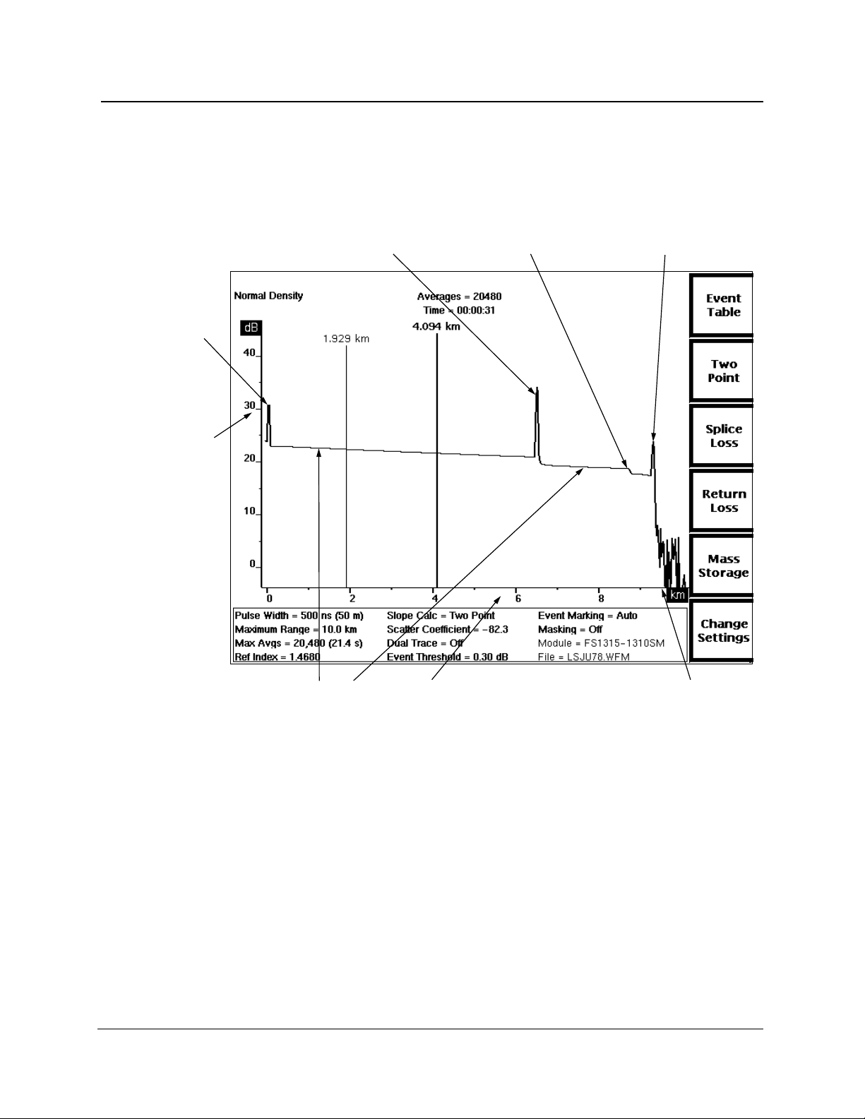
Chapter 1: Introduction
The Acquisition Screen
The acquisition screen displays fiber test data and measurement information, and is
used for all fiber-evaluation activity. Other than instrument setup, event marking, and
mass-storage operations, most of your work with FiberMaster will be on the
acquisition screen.
The acquisition screen displays either data acquisition in progress or a completed
acquisition, including all measurements on the fiber under test. Distance and loss
cursors display on this screen, depending on the measurement mode, and can be
manipulated to perform manual measurements on the fiber.
The acquisition screen includes:
❏ A horizontal distance scale and a vertical loss scale.
❏ One or two distance cursors, and one or two loss cursors, depending on the
measurement mode.
Vertical
scale (dB)
Inactive
distance
cursor
Waveform
settings
Expansion
window
Active
distance
cursor
Loss
cursors
Horizontal scale
(kilometers or kilofeet)
Softkey labels
Figure 1-2. Features on the Acquisition Screen
1-8 TFP2A FiberMaster User Manual
Page 28
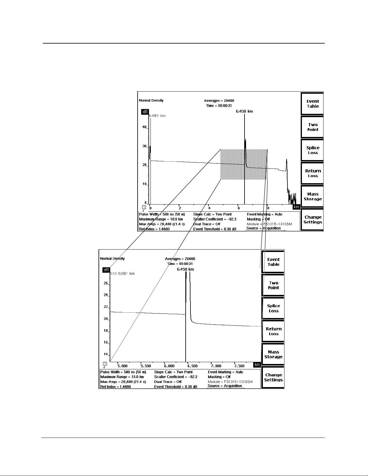
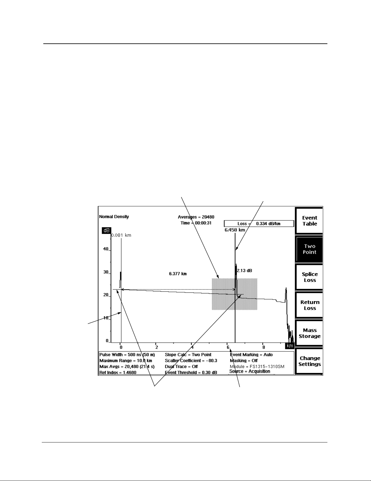
Chapter 1: Introduction
❏ An expansion window. Pressing the EXPAND button on the front panel switches
between expanded view and overview. In expanded view, the area within the
expansion window is magnified to fill the display, allowing closer examination of
the fiber. See figure 1-3.
Figure 1-3. Acquisition Screen Expansion—Overview (top),
and Expanded View (bottom)
TFP2A FiberMaster User Manual 1-9
Page 29

Chapter 1: Introduction
❏ Waveform and measurement data. Distance and loss measurements are
displayed on the screen near the waveform. In Two Point mode and both returnloss modes, the slope calculation and return loss, respectively, appears in the
upper right-hand corner of the screen. The message User Adjusted
Measurement displays in the upper left-hand corner of the screen for all
manually adjusted measurements. The actual number of averages that were
performed on the waveform, and the actual elapsed averaging time are shown in
the upper center screen. If an acquisition is in progress, the number of averages
and the time elapsed are seen increasing.
During an acquisition, the display also contains an acquisition-active indicator in
the lower-left corner of the waveform area. This indicator provides a quick way to
check whether an acquisition is still in progress. When data acquisition is
complete, and calculations are still in progress, the indicator changes to show a
clock with a swinging pendulum.
When event-marking mode is turned on, events on the fiber are marked and
numbered at the bottom of the acquisition screen. In addition, when the active
distance cursor is on an event marker, a field below the horizontal distance scale
displays measurements for that event.
❏ On color monitors, the waveform area of the acquisition screen is color coded for
easier interpretation of data and measurements. Waveform data, including the
active waveform (except for high-density data), the number of averages, elapsed
time, and the Normal Density or High Density message, is green. The useradjustable elements—distance and loss cursors, and the User Adjusted
Measurement message—are displayed in red. Measurement values such as the
two-point distance and loss, splice loss, fiber loss, and return loss figures are
shown in yellow. Event markers are also displayed in yellow.
1-10 TFP2A FiberMaster User Manual
Page 30

Chapter 1: Introduction
❏ All waveform settings used for the acquisition are displayed at the bottom of the
screen. These user-defined settings are selected on the Waveform Settings
menu, reached by pressing the Change Settings softkey on the acquisition
screen. Refer to chapter 3,
Getting Started
, for information on configuring your
instrument and setting parameters.
A Module parameter in the list of settings indicates which laser source is
currently selected. The type of module is shown, plus the currently selected
wavelength. For example, FS1315-1310SM indicates that the 1310-nm
wavelength of a dual-wavelength singlemode FS-type optical module is currently
selected. If the active module is different from the one that was used to acquire
the current waveform, the module parameter is highlighted.
The module parameter may include alphabetical characters to indicate the
modification level of the module, and whether the module has an internal fiber
with a non-standard core diameter. This information is appended to the
wavelength. Lower-case letters indicate the modification level of the module, and
upper-case letters stand for a non-standard core diameter. For example:
FS1315-1310SM — standard module with standard core diameter
FS1315-1310SMaA — modified module with non-standard core diameter
FS1315-1310SMA — standard module with non-standard core diameter
FS1315-1310SMa — modified module with standard core diameter
For more information on module modifications and internal fiber core diameters,
in the U.S. and Canada, call 1-800-833-9200, or contact your local Tektronix
representative.
The Source parameter shows where the current waveform data originated. The
data could be the result of an acquisition, a data transfer, or from a mass-storage
file. For an acquisition, the parameter displays as Source = Acquisition. If the
waveform was loaded from mass storage, the parameter reads File =
<FILE_NAME> where <FILE_NAME> is the name of the mass-storage file. If the
waveform data was received via an XModem data transfer, the parameter reads
Source = XModem.
❏ Softkey labels display along the right-hand edge of the screen. On the acquisition
screen, the softkeys allow you to switch measurement modes, view the event
table, enter the menu system, and access mass-storage functions.
TFP2A FiberMaster User Manual 1-11
Page 31

Chapter 1: Introduction
About this Manual
The FiberMaster User Manual consists of seven chapters and six appendices,
containing the following information:
❏ Chapter 1,
unpacking and repacking instructions, instrument specifications, and user
maintenance.
❏ Chapter 2,
of the front- and rear-panel controls and connectors.
❏ Chapter 3,
settings defaults, and describes the menu system used to configure the
instrument and set measurement parameters.
❏ Chapter 4,
measurement modes—Preview, Two Point, Splice Loss, Link Return Loss, and
Event Return Loss—and how to make automatic and manual measurements on
a fiber in these modes.
❏ Chapter 5,
documenting events on the fiber under test. Events can be marked either
automatically or manually. An event table of measurements is compiled, based
on the locations of the event markers.
❏ Chapter 6,
FiberMaster’s features, including details on the expansion window, high-density
data acquisition, dual waveform operation, and real-time mode.
❏ Chapter 7,
(floppy disk drive, internal RAM) to store and retrieve waveform and settings
data.
Introduction
, provides a description of the FiberMaster OTDR,
Controls, Indicators, and Connectors
Getting Started
, explains how to use the online help function, lists
Making Optical Fiber Measurements
Event Marking,
Advanced Operating Functions
Mass Storage
explains the process of locating, measuring, and
, outlines advanced aspects of some of
, explains how to use the mass-storage device(s)
, describes the functions of each
, describes each of the
❏ Chapter 8,
instructions on how to use the instrument under remote control via GPIB and RS-
232.
❏ Appendices contain information that applies to general operation of the
instrument. They include a list of options and accessories available for use with
the FiberMaster OTDR, a description of the instrument’s data output, a list of
keyboard sequences recognized by the instrument, how to run the instrument’s
diagnostic self tests, a list of firmware versions, a list of start-up error codes, and
instructions on how to upgrade software via floppy disk.
1-12 TFP2A FiberMaster User Manual
Remote Control
, contains the remote-control command set and
Page 32

Conventions Used
in this Manual
In the text of this manual, references to front-panel controls and softkeys appear in
boldface type, for example:
Press the START/STOP button.
Change instrument settings by pressing the Change Settings softkey.
Remote-control commands and messages as sent and received by the instrument
are shown indented and in upper-case, boldface type:
ACQUIRE 10.0,START,NORMAL;*OPC?
Change and History Information
Change information that involves manual corrections and additional data is located at
the back of this manual in the
the updated data is integrated into the text or diagrams when a page is updated.
Change Information
Chapter 1: Introduction
section. History information with
TFP2A FiberMaster User Manual 1-13
Page 33

Chapter 1: Introduction
Unpacking and Preparation for Use
Before unpacking FiberMaster from its shipping container or carton, inspect for signs
of external damage. If the carton is damaged, notify the carrier. The shipping carton
contains the instrument and its standard and optional accessories.
If the contents of the shipping container are incomplete, if there is mechanical
damage or defects, or if the instrument does not meet operational check
requirements, contact your local Tektronix Field Office or representative. If the
shipping container is damaged, notify the carrier as well as Tektronix.
The instrument was inspected both mechanically and electrically before shipment. It
should be free of mechanical damage and meet or exceed all electrical
specifications. Functional and operational self tests are performed at power-on. If
your instrument fails to perform satisfactorily, contact your Tektronix representative
immediately, or in the U.S. and Canada, telephone toll free 1-800-TEK-WIDE ext.
2400.
Preparation for Use
Use FiberMaster’s front cover to protect the front panel when storing and transporting
the instrument. Remove the cover by pulling out on the sides and lifting off. Replace
the cover by pressing it over the front panel until the cover snaps in place. The
instrument’s accessories are stored in the soft carrying case.
You can position FiberMaster’s handle to serve as a tilt stand, or you can move it to
the front of the instrument, so the instrument can be stacked or carried. To position
the handle, press in at both pivot points and rotate to the desired position.
Power Source and Power Requirements
FiberMaster is intended to be operated from a power source that does not apply more
than 250V RMS between the supply conductors, or between either supply conductor
and ground. A protective ground connection by way of the grounding conductor in the
power cord is essential for safe operation.
The AC power connector is a three-wide, polarized plug with the ground (earth) lead
connected directly to the instrument frame to provide electrical shock protection. If
the unit is connected to any other power source, the unit frame must be connected to
an earth ground.
CAUTION
To avoid electric shock, the power cord protective grounding conductor must be
connected to ground.
1-14 TFP2A FiberMaster User Manual
Page 34

Power and voltage requirements are printed on the back panel. With the DC power
option (option 17), FiberMaster can be operated from 11 to 16 VDC, or from 90 to
250 VAC nominal line voltage at 47 to 73 Hz. AC-only instruments can be operated
from 90 to 250 VAC, 47 to 73 Hz.; or from 90 to 130 VAC, 47 to 440 Hz. In AC-only
instruments, power-source selection is made automatically when the unit is plugged
in.
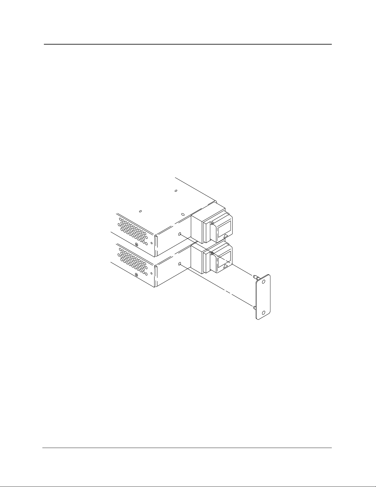
Installing the Optical Module(s)
Your TFP2A mainframe may be shipped with optical module(s) installed. If you order
modules separately, you may have to install them at your site. Install one or two
optical modules into the mainframe as follows:
1. Detach the left-hand side of the mainframe back panel by unscrewing four black
quick-release screws in each corner of the back-panel assembly (see figure 1-4).
Pull the back-panel assembly off the mainframe using the handle provided,
disconnecting the control and module support boardsfrom the interconnectboard,
which is attached to the inside of the back panel.
Backpanel
quick-release screws
Chapter 1: Introduction
Module
quick-release screws
Backpanel
quick-release screws
Figure 1-4. Installing Optical Modules
TFP2A FiberMaster User Manual 1-15
Page 35

Chapter 1: Introduction
(use for second module)
2. Plug one module into the bottom set of module connectors on the interconnect
board, inserting the module’s screwholes through the back-panel assembly. (See
figure 1-5.)
3. Secure the module to the back-panel assembly by tightening the two back-panel
quick-release screws into the module’s screwholes.
4. If you have a second module, plug it into the top set of module connectors on the
interconnect board.
Module support
board connectors
Module connectors
Module connectors
(use for single module)
Control board
connector
Figure 1-5. Interconnect Circuit Board Connectors
5. Secure the secondmodule to the back-panelassemblyby tightening the twoquick-
release screws into the module’s screwholes.
1-16 TFP2A FiberMaster User Manual
Page 36
Chapter 1: Introduction
6. If you are installing two modules, snap the spacer between the modules as shown
in figure 1-6, into the holes provided .
7. Place the modules inside the mainframe, lining up the fiber connectors with the
openings in the front panel, and reconnecting the control and module support
boards to the interconnect board.
NOTE
Align the connectors on the interconnect board correctly to ensure complete
connections with the module support board, optical module(s), and control board.
If connections are not made properly, the instrument will not work.
8. Reattach the back-panel assembly to the mainframe by tightening the four black
quick-release screws. All the screws in the back-panel assembly can be tightened
further using a screwdriver, if necessary.
To take the modules out of the TFP2A mainframe, reverse this procedure.
Figure 1-6. Installing the Module Spacer:
Two-Module Configuration
TFP2A FiberMaster User Manual 1-17
Page 37
Chapter 1: Introduction
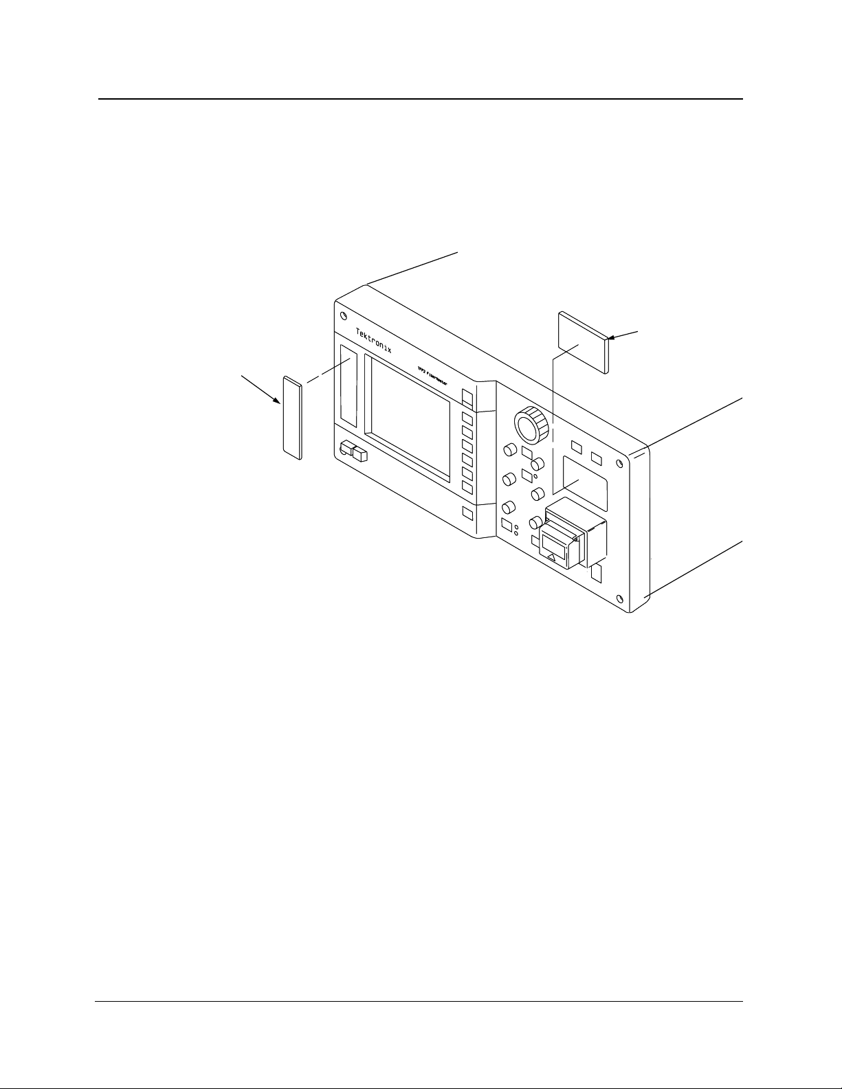
Front-Panel Covers
If your instrument includes one optical module, the top module slot on the front panel
is unused. If your instrument is not configured with a floppy-disk drive, the drive slot is
unused. Unused option slots are covered before the instrument is shipped from the
factory. If you change your instrument’s configuration, however, you may need to
remove or install these covers, as shown in figure 1-7.
Disk-drive
cover
Option-port
cover
Figure 1-7. Front-Panel Option Covers
1-18 TFP2A FiberMaster User Manual
Page 38
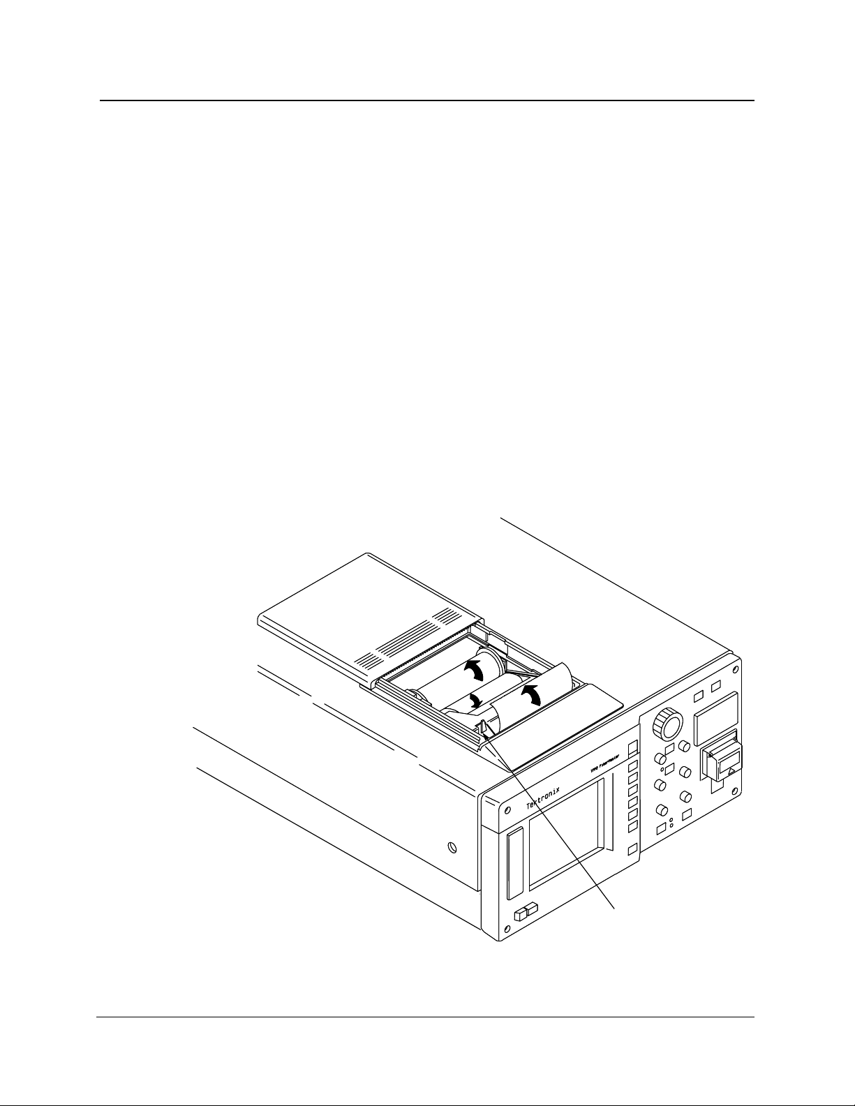
Loading Paper into the Internal Printer
To load paper into the internal thermal printer, follow these steps:
1. Slide the printer cover back.
2. Lift out the old paper roll and remove the black disks from either end.
3. Insert the disks into the ends of the new paper roll.
4. Place the new roll into the printer, with the end of the paper coming out from under
the roll towards the front of the instrument.
5. Push the paper tension lever down, and hold it down for step 6.
6. Feed the paper into the slot in the paper guide, until it comes out in front of the
aluminum paper guide. See figure 1-8. The arrows indicate the direction in which
to feed the paper.
7. Release the tension lever.
When the printer is in use, slide the printer cover closed until it reaches the stops
provided for the paper opening. Use the serrated edge of the cover as a guide to tear
the paper off. After printing, tear off any remaining paper and slide the cover
completely closed over the printer.
Chapter 1: Introduction
Paper tension
lever
Figure 1-8. Loading Paper into the Internal Printer
TFP2A FiberMaster User Manual 1-19
Page 39

Chapter 1: Introduction
Laser Output
FiberMaster is equipped with low-energy lasers and does not output continuous
energy unless you have started data acquisition (by pressing the START/STOP button).
WARNING
The TFP2A FiberMaster has been classified as a Class 1 laser product under the
Radiation Control and Health Safety Act of 1968.
Although output from a Class 1 laser is not considered hazardous, it is good
practice not to allow eye exposure from direct or reflected laser light. This can be
avoided by covering the end of the fiber or directing the output at a non-reflective
surface.
It is important to set up and operate the instrument as instructed in this manual.
Use of controls or adjustments for performance of procedures other than those
specified herein may result in hazardous radiation exposure.
Repacking for Shipment
When packing an instrument for shipping to a Tektronix Service Center for service or
repair, attach a tag showing the name and address of the owner, name of the
individual at your firm to contact, complete serial number, and a description of the
service required. If the original packaging is not available, repackage the instrument
as follows:
1. Install the front cover on the OTDR.
2. Position the handle over the front cover, and wrap the instrument in polyethylene
sheeting to protect the finish.
3. Cushion the instrument on all sides with packing material or urethane foam
between the carton and the sides of the instrument.
4. Seal the carton using shipping tape.
No special handling is required to prepare the floppy-disk drive for shipping.
A shipping carton and packing material can be obtained through your local Tektronix
field office or representative, if necessary.
If you have any questions, contact your local Tektronix field office or representative or
in the U.S. and Canada call toll free 1-800-TEK-WIDE ext. 2400.G
1-20 TFP2A FiberMaster User Manual
Page 40

Specifications
Electrical Characteristics
The following characteristics and features apply to the FiberMaster OTDR after a
warmup period of at least 20 minutes. All loss numbers reflect one-way
measurements unless otherwise specified.
Table 1-1. Display Range—Vertical System
Chapter 1: Introduction
Vertical range
Loss measurements
Loss readout resolution
Accuracy
Two point, splice loss, and
LSA fiber loss:
FM/FS/FG series
FL series
1 dB to 50 dB, overview
1 dB to 100 dB, expanded view
0.001 dB to 0.01 dB
±0.05 dB/dB, from 7 dB above the RMS noise floor
(SNR = 1) to 30 dB on the screen. Maximum error of
±0.2 dB from +7 dB above the RMS noise floor to
top of backscatter.
±0.02 dB/dB, from 15 dB to 35 dB on the screen.
TFP2A FiberMaster User Manual 1-21
Page 41

Chapter 1: Introduction
Table 1-2. Display Range—Horizontal System
Distance range
Distance measurements
Cursor resolution (min)
FM/FS/FG series:
850 nm MM
1300 nm MM/
1310 nm SM/
1550 nm SM
FL series:
1310 SM/
1550 SM
Index of refraction range
Distance measurement
accuracy
Number of displayed
waveform points
1 m to 200 km
5 cm to 2 m, normal density;
1 cm to 50 cm, high density
20 cm to10 m, normal density;
10 cm to 2 m, high density
2 m to 10 m, normal density;
no high density
1.4000 to 1.6000
±0.001%, ±minimum cursor resolution
±uncertainty in index of refraction
>16,000 maximum for each normal and
high density
Table 1-3. Display
Size
Resolution
Display type
Color
Monochrome
Table 1-4. Keyboard
Connector
Compatibility
7 inches (17.5 cm) diagonal
640 by 480 pixels
Two-color system giving three colors, with five
levels each
Five-level gray scale
5-pin RJ11
Compatible with IBM AT keyboards (input
only), but complete compatibility can be
guarenteed only with Tektronix keyboard
Option 19
1-22 TFP2A FiberMaster User Manual
Page 42

Table 1-5. Hardcopy
Chapter 1: Introduction
Internal printer
Resolution
Print dimensions
External plotter
External printer
Table 1-6. Mass Storage
Floppy disk drive
Size
Capacity
Format
Internal RAM
Capacity
Battery life
High-speed, high-resolution dot matrix, thermal
150 dots/in vertical and horizontal
4 in by 5 in (10.2 cm by 12.7 cm)
HP-GL compatible (Tektronix HC100): GPIB and RS232
connections
Epson FX-compatible: RS232 connection
Hewlett-Packard ThinkJet/LaserJet-compatible: GPIB
and RS232 connections
PostScript-compatible: RS232 connection
3.5 in (8.9 cm)
1.44 Mbyte or 720 Kbyte
MS-DOS compatible
1 Mbyte
1 year
TFP2A FiberMaster User Manual 1-23
Page 43

Chapter 1: Introduction
Operational Characteristics
Table 1-7. Operational Characteristics
Power requirements
AC operation (AC only)
90 - 130 VAC, 47 - 440Hz
180 - 250 VAC, 47 - 73Hz
(auto select)
AC operation (AC with DC option)
DC operation
Power supply rating
AC operation
DC operation
Module capacity
Safety
Physical Characteristics
90 - 130 VAC, 47 - 73 Hz
180 - 250 VAC, 47 - 73 Hz
11 - 16 VDC
250 watts max.
315 VA max.
200 VA max. (watts)
Two dual-wavelength modules
maximum, for a total of four
wavelengths
UL 1244, UL 3111-1
CSA: CAN/CSA C22.2 No. 231
CAN/CSA -C22.2 No. 1010.192
IEC 1010-1
EN 61010-1
Table 1-8. Physical Characteristics
Weight
Dimensions
1-24 TFP2A FiberMaster User Manual
33 lbs (15 kg), mainframe configured with floppydisk drive, internal printer, and one optical module
Overall dimensions, including front cover, handle,
and feet:
Length, 25 in (63.7 cm);
width, 18 in (46 cm);
height, 7 in (18 cm)
Page 44

Environmental Characteristics
Table 1-9. Environmental Characteristics
Temperature
Mainframe
Chapter 1: Introduction
Operating: +5˚ to +50˚ C
Non-operating: -40˚ to +60˚ C
With internal printer
Without floppy-disk drive
Humidity (operating)
Mainframe
With internal printer
Without floppy-disk drive
Altitude (maximum)
Operating
Non-operating
Sine vibration
Operating
Disk drive non-operating
Shock (maximum)
Operating
Operating: +5˚ to +40˚ C
Non-operating: -20˚ to +60˚ C
Operating: -10˚ to +55˚ C
Non-operating: -40˚ to +70˚ C
8% to 75% (+5%, -0%), noncondensing
35% to 75% (+5%, -0%), noncondensing
5% to 90% (+5%, -0%), noncondensing
15,000 ft (4.6 km)
50,000 ft (15.2 km)
Tek 062-2847-00, Class 3 (exceeds MIL-T28800E)
Frequency sweep: 10 to 55 Hz
Loading: 0.5G, maximum
Frequency sweep: 10 to 55 Hz
Loading: 2.0G, maximum
5G
Disk drive non-operating
Bench handling
Transit drop
Water resistance
Fungus resistance
TFP2A FiberMaster User Manual 1-25
30G
MIL-T-28800E
MIL-T-28800E
Drip proof, tested with front cover on
Enclosure and electronics are fungus inert by
design
Page 45

Chapter 1: Introduction
Table 1-9. Environmental Characteristics, cont.
Electromagnetic
compatibility
Emissions:
Radiated emissions
Mains Current Harmonics
Conducted emissions
Magnetic emissions
Immunity:
IEC 1000-4-2
IEC 1000-4-3
IEC 1000-4-4
IEC 1000-4-5
IEC 1000-4-11
EC Council Directive 89/336/EEC
EN 50081-1
FCC Part 15, Subpart J, Class A
EN55022, Class B
IEC 1000-3-2
FCC Part 15, Subpart J, Class A
EN55022, Class B
EN60555-2
Vfg 243, Class B
EN 50082-1
Electrostatic Discharge
RF Radiated
Fast Transients
Surge
Dropout
1-26 TFP2A FiberMaster User Manual
Page 46

FS1300 Singlemode Optical Module
Table 1-10. FS1300 Singlemode Optical Module
Chapter 1: Introduction
Dynamic Range
1
Dead Zone
Pulse End Loss
Width SNR = 1 (dB)
2
Detect. (dB)
3
Meas. (m)
4
Event (m)
5
10 µs/1000 m 29.5 38.0 1080 1050
4000 ns/400 m 27.5 38.0 480 420
2000 ns/200 m 23.5 38.0 240 220
1000 ns/100 m 22.0 38.0 140 110
500 ns/50 m 20.5 38.0 70 55
200 ns/20 m 18.5 38.0 40 25
100 ns/10 m 17.0 38.0 25 12
50 ns/5 m 15.5 38.0 20 7
50 ns/5 m HR 12.0 34.0 15 7
20 ns/2 m HR 10.5 34.0 NA 5
10 ns/1 m HR 9.0 34.0 NA 3
Operating wavelength: 1310 nm ± 20 nm
Masking: menu selectable
❏ Auto-QuickMask
❏ Auto-AccuMask
❏ Manual-QuickMask
❏ Manual-AccuMask
Full-screen display range: 50 m to 200 km
Laser safety: Class 1, 21 CFR 1040
Temperature: -10˚ to +55˚ C operating; -40˚ to +70˚ C non-operating
Humidity: Up to 90% relative humidity (+5, -0%)
Weight: 4.4 lbs (<2 kg)
Dimensions: 1.75 in (4.5 cm) by 5.5 in (14.0 cm) by 17.5 in (44.5 cm)
1
Dynamic range specifications are based on 32,000 averages. Actual averaging
times depend on instrument settings. For 3 Sigma values, subtract 2.4 dB from
SNR=1 values.
2
Dynamic range, SNR = 1 is the one-way difference between the extrapolated
backscatter level at the start of the fiber and the RMS noise level.
3
Dynamic range, end detection is the one-way difference between the top of a 4%
Fresnel reflection at the start of the fiber and the 3 Sigma (99.5%) level of the noise.
4
Dead zone, loss measurement is the minimum distance after any reflective event
on the display to measure loss to within 0.5 dB of backscatter.
5
Dead zone, event (two-point spatial resolution) is the minimum distance after any
reflection necessary to determine accurately the distance to another event (based on
a minimum recover of 1.5 dB down from the top of the first reflection).
TFP2A FiberMaster User Manual 1-27
Page 47

Chapter 1: Introduction
FS1500 Singlemode Optical Module
Table 1-11. FS1500 Singlemode Optical Module
Dynamic Range
1
Dead Zone
Pulse End Loss
Width SNR = 1 (dB)
2
Detect. (dB)
3
Meas. (m)
4
Event (m)
10 µs/1000 m 26.5 36.0 1080 1050
4000 ns/400 m 24.5 36.0 480 420
2000 ns/200 m 20.5 36.0 240 220
1000 ns/100 m 19.0 36.0 140 110
500 ns/50 m 17.5 36.0 70 55
200 ns/20 m 15.5 36.0 40 25
100 ns/10 m 14.0 36.0 25 12
50 ns/5 m 12.5 36.0 20 7
50 ns/5 m HR 9.0 33.0 18 7
20 ns/2 m HR 7.5 33.0 NA 5
10 ns/1 m HR 5.0 33.0 NA 3
Operating wavelength: 1550 nm ± 20 nm
Masking: menu selectable
❏ Auto-QuickMask
❏ Auto-AccuMask
❏ Manual-QuickMask
❏ Manual-AccuMask
Full-screen display range: 50 m to 200 km
Laser safety: Class 1, 21 CFR 1040
Temperature: -10˚ to +55˚ C operating; -40˚ to +70˚ C non-operating
Humidity: Up to 90% relative humidity (+5, -0%)
Weight: 4.4 lbs (<2 kg)
Dimensions: 1.75 in (4.5 cm) by 5.5 in (14.0 cm) by 17.5 in (44.5 cm)
1
Dynamic range specifications are based on 32,000 averages. Actual averaging
times depend on instrument settings. For 3 Sigma values, subtract 2.4 dB from
SNR=1 values.
2
Dynamic range, SNR = 1 is the one-way difference between the extrapolated
backscatter level at the start of the fiber and the RMS noise level.
3
Dynamic range, end detection is the one-way difference between the top of a 4%
Fresnel reflection at the start of the fiber and the 3 Sigma (99.5%) level of the noise.
4
Dead zone, loss measurement is the minimum distance after any reflective event
on the display to measure loss to within 0.5 dB of backscatter.
5
Dead zone, event (two-point spatial resolution) is the minimum distance after any
reflection necessary to determine accurately the distance to another event (based on
a minimum recover of 1.5 dB down from the top of the first reflection).
5
1-28 TFP2A FiberMaster User Manual
Page 48

FS1315 Singlemode Optical Module
Table 1-12. FS1315 Singlemode Optical Module
Chapter 1: Introduction
Dynamic Range
1
Dead Zone
Pulse End Loss
Width SNR = 1 (dB)
2
Detect. (dB)
3
Meas. (m)
4
Event (m)
10 µs/1000 m 29.5/26.5 38.0/36.0 1080 1050
4000 ns/400 m 27.5/24.5 38.0/36.0 480 420
2000 ns/200 m 23.5/20.5 38.0/36.0 240 220
1000 ns/100 m 22.0/19.0 38.0/36.0 140 110
500 ns/50 m 20.5/17.5 38.0/36.0 70 55
200 ns/20 m 18.5/15.5 38.0/36.0 40 25
100 ns/10 m 17.0/14.0 38.0/36.0 25 12
50 ns/5 m 15.5/12.5 38.0/36.0 20 7
50 ns/5 m HR 12.0/9.0 34.0/33.0 15/18 7
20 ns/2 m HR 10.5/7.5 34.0/33.0 NA 5
10 ns/1 m HR 9.0/5.0 34.0/33.0 NA 3
Operating wavelengths: 1310/1550 nm ± 20 nm
Masking: menu selectable
❏ Auto-QuickMask
❏ Auto-AccuMask
❏ Manual-QuickMask
❏ Manual-AccuMask
Full-screen display range: 50 m to 200 km
Laser safety: Class 1, 21 CFR 1040
Temperature: -10˚ to +55˚ C operating; -40˚ to +70˚ C non-operating
Humidity: Up to 90% relative humidity (+5, -0%)
Weight: 4.4 lbs (<2 kg)
Dimensions: 1.75 in (4.5 cm) by 5.5 in (14.0 cm) by 17.5 in (44.5 cm)
1
Dynamic range specifications are based on 32,000 averages. Actual averaging
times depend on instrument settings. For 3 Sigma values, subtract 2.4 dB from
SNR=1 values.
2
Dynamic range, SNR = 1 is the one-way difference between the extrapolated
backscatter level at the start of the fiber and the RMS noise level.
3
Dynamic range, end detection is the one-way difference between the top of a 4%
Fresnel reflection at the start of the fiber and the 3 Sigma (99.5%) level of the noise.
4
Dead zone, loss measurement is the minimum distance after any reflective event
on the display to measure loss to within 0.5 dB of backscatter.
5
Dead zone, event (two-point spatial resolution) is the minimum distance after any
reflection necessary to determine accurately the distance to another event (based on
a minimum recover of 1.5 dB down from the top of the first reflection).
5
TFP2A FiberMaster User Manual 1-29
Page 49

Chapter 1: Introduction
FG1300 Singlemode Optical Module
Table 1-13. FG1300 Singlemode Optical Module
Dynamic Range
1
Dead Zone
Pulse End Loss
Width SNR = 1 (dB)
2
Detect. (dB)
3
Meas. (m)
4
Event (m)
5
10 µs/1000 m 31.0 38.0 1150 1150
4000 ns/400 m 28.5 38.0 550 475
2000 ns/200 m 25.5 38.0 250 225
1000 ns/100 m 24.0 38.0 150 110
500 ns/50 m 21.5 38.0 80 55
200 ns/20 m 19.5 38.0 55 25
100 ns/10 m 18.0 38.0 50 12
50 ns/5 m 16.5 38.0 45 10
50 ns/5 m HR 13.5 34.0 30 7
20 ns/2 m HR 11.5 34.0 25 5
10 ns/1 m HR 9.5 34.0 N/A 4
Operating wavelength: 1310 nm ± 20 nm
Masking: not applicable
Full-screen display range: 50 m to 200 km
Laser safety: Class 1, 21 CFR 1040
Temperature: -10˚ to +55˚ C operating; -30˚ to +70˚ C non-operating
Humidity: Up to 90% relative humidity (+5, -0%)
Weight: 4.4 lbs (<2 kg)
Dimensions: 1.75 in (4.5 cm) by 5.5 in (14.0 cm) by 17.5 in (44.5 cm)
1
Dynamic range specifications are based on 32,000 averages. Actual averaging
times depend on instrument settings.
2
Dynamic range, SNR = 1 is the one-way difference between the extrapolated
backscatter level at the start of the fiber and the RMS noise level.
3
Dynamic range, end detection is the one-way difference between the top of a 4%
Fresnel reflection at the start of the fiber and the 3 Sigma (99.5%) level of the noise.
4
Dead zone, loss measurement is the minimum distance after any reflective event
on the display to measure loss to within 0.5 dB of backscatter. Specifications are
based on reflections not to exceed a return loss of 40 dB.
5
Dead zone, event (two-point spatial resolution) is the minimum distance after any
reflection necessary to determine accurately the distance to another event (based on
a minimum recover of 1.5 dB down from the top of the first reflection).
Performance specifications are at 25˚ C.
1-30 TFP2A FiberMaster User Manual
Page 50

FG1315 Singlemode Optical Module
Table 1-14. FG1315 Singlemode Optical Module
Chapter 1: Introduction
Dynamic Range
1
Dead Zone
Pulse End Loss
Width SNR = 1 (dB)
2
Detect. (dB)
3
Meas. (m)
4
Event (m)
10 µs/1000 m 31.0/29.0 38.0/36.0 1150 1150
4000 ns/400 m 28.5/26.5 38.0/36.0 550 475
2000 ns/200 m 25.5/23.5 38.0/36.0 250 225
1000 ns/100 m 24.0/22.0 38.0/36.0 150 110
500 ns/50 m 21.5/19.5 38.0/36.0 80/85 55
200 ns/20 m 19.5/17.5 38.0/36.0 55/60 25
100 ns/10 m 18.0/16.0 38.0/36.0 50/55 12
50 ns/5 m 16.5/14.5 38.0/36.0 45/55 10
50 ns/5 m HR 13.5/11.5 34.0/33.0 30/35 7
20 ns/2 m HR 11.5/9.5 34.0/33.0 25/30 5
10 ns/1 m HR 9.5/7.5 34.0/33.0 N/A 4
Operating wavelengths: 1310/1550 nm ± 20 nm
Masking: not applicable
Full-screen display range: 50 m to 200 km
Laser safety: Class 1, 21 CFR 1040
Temperature: -10˚ to +55˚ C operating; -30˚ to +70˚ C non-operating
Humidity: Up to 90% relative humidity (+5, -0%)
Weight: 4.4 lbs (<2 kg)
Dimensions: 1.75 in (4.5 cm) by 5.5 in (14.0 cm) by 17.5 in (44.5 cm)
1
Dynamic range specifications are based on 32,000 averages. Actual averaging
times depend on instrument settings.
2
Dynamic range, SNR = 1 is the one-way difference between the extrapolated
backscatter level at the start of the fiber and the RMS noise level.
3
Dynamic range, end detection is the one-way difference between the top of a 4%
Fresnel reflection at the start of the fiber and the 3 Sigma (99.5%) level of the noise.
4
Dead zone, loss measurement is the minimum distance after any reflective event
on the display to measure loss to within 0.5 dB of backscatter. Specifications are
based on reflections not to exceed a return loss of 40 dB.
5
Dead zone, event (two-point spatial resolution) is the minimum distance after any
reflection necessary to determine accurately the distance to another event (based on
a minimum recover of 1.5 dB down from the top of the first reflection).
Performance specifications are at 25˚ C.
5
TFP2A FiberMaster User Manual 1-31
Page 51

Chapter 1: Introduction
FL1300 Singlemode Optical Module
Table 1-15. FL1300 Singlemode Optical Module
Dynamic Range
1
Dead Zone
Pulse End
SNR = 1 (dB)
2
Detect (dB)
3
Meas. (m)
4
Event (m)
5
20 µs/2000 m 37.5 46.0 2375 2100
10 µs/1000 m 36.0 46.0 1270 1050
4000 ns/400 m 33.5 45.5 670 440
2000 ns/200 m 31.0 44.5 395 220
1000 ns/100 m 29.5 44.5 280 120
500 ns/50 m 27.5 44.0 150 60
200 ns/20 m 25.5 44.0 125 35
100 ns/10 m 24.0 44.0 125 25
Operating wavelength: 1310 nm ± 20 nm
Masking: not applicable
Full-screen display range: 50 m to 320 km
Laser safety: Class 1, 21 CFR 1040
Temperature: -10˚ to +55˚ C operating; -40˚ to +70˚ C non-operating
Humidity: Up to 90% relative humidity (+5, -0%)
Weight: 4.4 lbs (<2 kg)
Dimensions: 1.75 in (4.5 cm) by 5.5 in (14.0 cm) by 17.5 in (44.5 cm)
1
Dynamic range specifications are based on 262,000 averages. Actual averaging
times depend on instrument settings. For 3 Sigma values, subtract 2.4 dB from
SNR=1 values.
2
Dynamic range, SNR = 1 is the one-way difference between the extrapolated
backscatter level at the start of the fiber and the RMS noise level.
3
Dynamic range, end detection is the one-way difference between the top of a 4%
Fresnel reflection at the start of the fiber and the 3 Sigma (99.5%) level of the noise.
4
Dead zone, loss measurement is the minimum distance after any reflective event
on the display to measure loss to within 0.5 dB of backscatter.
5
Dead zone, event (two-point spatial resolution) is the minimum distance after any
reflection necessary to determine accurately the distance to another event (based on
a minimum recover of 1.5 dB down from the top of the first reflection).
1-32 TFP2A FiberMaster User Manual
Page 52

FL1500 Singlemode Optical Module
Table 1-16. FL1500 Singlemode Optical Module
Chapter 1: Introduction
Dynamic Range
1
Dead Zone
Pulse End
SNR = 1 (dB)
2
Detect (dB)
3
Meas. (m)
4
Event (m)
5
20 µs/2000 m 37.0 46.5 2375 2100
10 µs/1000 m 35.0 46.0 1270 1050
4000 ns/400 m 33.0 46.0 670 440
2000 ns/200 m 30.5 45.0 395 220
1000 ns/100 m 29.0 45.0 280 120
500 ns/50 m 27.0 44.5 150 60
200 ns/20 m 25.0 44.5 195 35
100 ns/10 m 23.0 44.0 170 25
Operating wavelength: 1550 nm ± 20 nm
Masking: not applicable
Full-screen display range: 50 m to 320 km
Laser safety: Class 1, 21 CFR 1040
Temperature: -10˚ to +55˚ C operating; -40˚ to +70˚ C non-operating
Humidity: Up to 90% relative humidity (+5, -0%)
Weight: 4.4 lbs (<2 kg)
Dimensions: 1.75 in (4.5 cm) by 5.5 in (14.0 cm) by 17.5 in (44.5 cm)
1
Dynamic range specifications are based on 262,000 averages. Actual averaging
times depend on instrument settings. For 3 Sigma values, subtract 2.4 dB from
SNR=1 values.
2
Dynamic range, SNR = 1 is the one-way difference between the extrapolated
backscatter level at the start of the fiber and the RMS noise level.
3
Dynamic range, end detection is the one-way difference between the top of a 4%
Fresnel reflection at the start of the fiber and the 3 Sigma (99.5%) level of the noise.
4
Dead zone, loss measurement is the minimum distance after any reflective event
on the display to measure loss to within 0.5 dB of backscatter.
5
Dead zone, event (two-point spatial resolution) is the minimum distance after any
reflection necessary to determine accurately the distance to another event (based on
a minimum recover of 1.5 dB down from the top of the first reflection).
TFP2A FiberMaster User Manual 1-33
Page 53

Chapter 1: Introduction
FL1315 Singlemode Optical Module
Table 1-17. FL1315 Singlemode Optical Module
Dynamic Range
1
Dead Zone
Pulse End
SNR = 1 (dB)
2
Detect (dB)
3
Meas. (m)
4
Event (m)
5
20 µs/2000 m 37.5/37.0 46.0/46.5 2375 2100
10 µs/1000 m 36.0/35.0 46.0/46.0 1270 1050
4000 ns/400 m 33.5/33.0 45.5/46.0 670 440
2000 ns/200 m 31.0/30.5 44.5/45.0 395 220
1000 ns/100 m 29.5/29.0 44.5/45.0 280 120
500 ns/50 m 27.5/27.0 44.0/44.5 150 60
200 ns/20 m 25.5/25.0 44.0/44.5 125/195 35
100 ns/10 m 24.0/23.0 44.0/44.0 125/170 25
Operating wavelength: 1310/1550 nm ± 20 nm
Masking: not applicable
Full-screen display range: 50 m to 320 km
Laser safety: Class 1, 21 CFR 1040
Temperature: -10˚ to +55˚ C operating; -40˚ to +70˚ C non-operating
Humidity: Up to 90% relative humidity (+5, -0%)
Weight: 4.4 lbs (<2 kg)
Dimensions: 1.75 in (4.5 cm) by 5.5 in (14.0 cm) by 17.5 in (44.5 cm)
1
Dynamic range specifications are based on 262,000 averages. Actual averaging
times depend on instrument settings. For 3 Sigma values, subtract 2.4 dB from
SNR=1 values.
2
Dynamic range, SNR = 1 is the one-way difference between the extrapolated
backscatter level at the start of the fiber and the RMS noise level.
3
Dynamic range, end detection is the one-way difference between the top of a 4%
Fresnel reflection at the start of the fiber and the 3 Sigma (99.5%) level of the noise.
4
Dead zone, loss measurement is the minimum distance after any reflective event
on the display to measure loss to within 0.5 dB of backscatter.
5
Dead zone, event (two-point spatial resolution) is the minimum distance after any
reflection necessary to determine accurately the distance to another event (based on
a minimum recover of 1.5 dB down from the top of the first reflection).
1-34 TFP2A FiberMaster User Manual
Page 54

FM8500 Multimode Optical Module
Table 1-18. FM8500 Multimode Optical Module
Chapter 1: Introduction
Dynamic Range
1
Dead Zone
Pulse End Loss
Width SNR = 1 (dB)
2
Detect. (dB)
3
Meas. (m)
4
Event (m)
5
100 ns/10 m 27.0 36.0 13.0 10.5
50 ns/5 m 25.5 36.0 8.5 5.5
20 ns/2 m 23.5 36.0 6.0 3.0
8 ns/80 cm 20.5 36.0 4.5 1.0
3 ns/30 cm 16.5 35.0 3.5 0.5
1 ns/10 cm 14.0 35.0 2.5 0.2
Operating wavelength: 850 nm ± 25 nm
Masking: not applicable
Full-screen display range: 5 m to 20 km
Laser safety: Class 1, 21 CFR 1040
Temperature: 0˚ to +50˚ C operating; -40˚ to +70˚ C non-operating
Humidity: Up to 90% relative humidity (+5, -0%)
Weight: 4.4 lbs (<2 kg)
Dimensions: 1.75 in (4.5 cm) by 5.5 in (14.0 cm) by 17.5 in (44.5 cm)
1
Dynamic range specifications are based on 32,000 averages. Actual averaging
times depend on instrument settings. For 3 Sigma values, subtract 2.4 dB from
SNR=1 values.
2
Dynamic range, SNR = 1 is the one-way difference between the extrapolated
backscatter level at the start of the fiber and the RMS noise level.
3
Dynamic range, end detection is the one-way difference between the top of a 4%
Fresnel reflection at the start of the fiber and the 3 Sigma (99.5%) level of the noise.
4
Dead zone, loss measurement is the minimum distance after any reflective event
on the display to measure loss to within 0.5 dB of backscatter.
5
Dead zone, event (two-point spatial resolution) is the minimum distance after any
reflection necessary to determine accurately the distance to another event (based on
a minimum recover of 1.5 dB down from the top of the first reflection).
TFP2A FiberMaster User Manual 1-35
Page 55

Chapter 1: Introduction
FM1300 Multimode Optical Module
Table 1-19. FM1300 Multimode Optical Module
Dynamic Range
1
Dead Zone
Pulse End Loss
Width SNR = 1 (dB)
2
Detect. (dB)
3
Meas. (m)
4
Event (m)
1000 ns/100 m 26.5 38.0 125 110
500 ns/50 m 23.5 38.0 65 55
200 ns/20 m 21.5 38.0 35 25
100 ns/10 m 20.0 38.0 30 12
50 ns/5 m 18.5 38.0 25 7
50 ns/5 m HR 15.0 35.0 20 7
20 ns/2 m HR 13.0 35.0 18 5
10 ns/1 m HR 15.0 35.0 14 3
Operating wavelength: 1300 nm ± 30 nm
Masking: not applicable
Full-screen display range: 50 m to 100 km
Laser safety: Class 1, 21 CFR 1040
Temperature: 0˚ to +50˚ C operating; -40˚ to +70˚ C non-operating
Humidity: Up to 90% relative humidity (+5, -0%)
Weight: 4.4 lbs (<2 kg)
Dimensions: 1.75 in (4.5 cm) by 5.5 in (14.0 cm) by 17.5 in (44.5 cm)
1
Dynamic range specifications are based on 32,000 averages. Actual averaging
times depend on instrument settings. For 3 Sigma values, subtract 2.4 dB from
SNR=1 values.
2
Dynamic range, SNR = 1 is the one-way difference between the extrapolated
backscatter level at the start of the fiber and the RMS noise level.
3
Dynamic range, end detection is the one-way difference between the top of a 4%
Fresnel reflection at the start of the fiber and the 3 Sigma (99.5%) level of the noise.
4
Dead zone, loss measurement is the minimum distance after any reflective event
on the display to measure loss to within 0.5 dB of backscatter.
5
Dead zone, event (two-point spatial resolution) is the minimum distance after any
reflection necessary to determine accurately the distance to another event (based on
a minimum recover of 1.5 dB down from the top of the first reflection).
5
1-36 TFP2A FiberMaster User Manual
Page 56

FM8513 Multimode Optical Module
Table 1-20. FM8513 Multimode Optical Module
Chapter 1: Introduction
Dynamic Range
1
Dead Zone
Pulse End Loss
Width SNR = 1 (dB)
2
Detect. (dB)
3
Meas. (m)
4
Event (m)
850 nm:
100 ns/10 m 27.0 36.0 13.0 10.5
50 ns/5 m 25.5 36.0 8.5 5.5
20 ns/2 m 23.5 36.0 6.0 3.0
8 ns/80 cm 20.5 36.0 4.5 1.0
3 ns/30 cm 16.5 35.0 3.5 0.5
1 ns/10 cm 14.0 35.0 2.5 0.2
1300 nm:
1000 ns/100 m 26.5 38.0 125 110
500 ns/50 m 23.5 38.0 65 55
200 ns/20 m 21.5 38.0 35 25
100 ns/10 m 20.0 38.0 30 12
50 ns/5 m 18.5 38.0 25 7
50 ns/5 m HR 15.0 35.0 20 7
20 ns/2 m HR 13.0 35.0 18 5
10 ns/1 m HR 15.0 35.0 14 3
5
Operating wavelengths: 850 nm ± 25 nm, 1300 nm ± 30 nm
Masking: not applicable
Full-screen display range: 850 nm—5 m to 20 km; 1300 nm—50 m to 100 km
Laser safety: Class 1, 21 CFR 1040
Temperature: 0˚ to +50˚ C operating; -40˚ to +70˚ C non-operating
Humidity: Up to 90% relative humidity (+5, -0%)
Weight: 4.4 lbs (<2 kg)
Dimensions: 1.75 in (4.5 cm) by 5.5 in (14.0 cm) by 17.5 in (44.5 cm)
1
Dynamic range specifications are based on 32,000 averages. Actual averaging
times depend on instrument settings. For 3 Sigma values, subtract 2.4 dB from
SNR=1 values.
2
Dynamic range, SNR = 1 is the one-way difference between the extrapolated
backscatter level at the start of the fiber and the RMS noise level.
3
Dynamic range, end detection is the one-way difference between the top of a 4%
Fresnel reflection at the start of the fiber and the 3 Sigma (99.5%) level of the noise.
4
Dead zone, loss measurement is the minimum distance after any reflective event
on the display to measure loss to within 0.5 dB of backscatter.
5
Dead zone, event (two-point spatial resolution) is the minimum distance after any
reflection necessary to determine accurately the distance to another event (based on
a minimum recover of 1.5 dB down from the top of the first reflection).
TFP2A FiberMaster User Manual 1-37
Page 57

Chapter 1: Introduction
Inspection, Cleaning, and Maintenance
FiberMaster’s cabinet minimizes dust accumulation inside the instrument. Never
operate the OTDR without the cabinet installed. When storing or transporting the
instrument, make sure the front cover is on to protect the front panel and display from
dust and damage.
Inspect and clean your FiberMaster OTDR as often as operating conditions require.
For example, under average conditions (laboratory use), inspect and clean your
instrument after every 1000 hours of operation. When using FiberMaster extensively
in the field, inspect and clean it after every 500 hours of operation. Dirt acts as a
thermal insulator and can cause overheating and component breakdown. It also
provides an electrical conduction path that could cause instrument failure, especially
under high-humidity conditions.
External inspection and cleaning procedures are included in this section. Internal
inspection and cleaning are beyond the scope of the user manual, and are included
in the
FiberMaster Module-Level Service Manual
and disassembly procedures and instructions on inspecting and cleaning the interior
of the instrument.
. Refer to this manual for assembly
Exterior Inspection
Inspect the outside of the OTDR for damage, wear, and missing parts, using table
1-19 as a guide. OTDRs that appear to have been dropped or otherwise abused
should be checked thoroughly to verify correct operation and performance.
Table 1-21. External Inspection Checklist
Item Inspect For Repair Action
Cabinet, front panel Cracks, scratches, Replace defective module.
cover, handle deformations, damaged
Front-panel knobs Missing, damaged, or loose Repair or replace missing or
Connectors Broken shells, cracked Replace defective modules.
Accessories Missing items or parts of Replace damaged or
hardware or gaskets,
proper operation of handle
knobs damaged knobs.
insulation, deformed contacts. Clear or wash out dirt.
Dirt in connectors.
items, bent pins, broken or missing items, frayed
frayed cables, and damaged cables, and defective
connectors. modules.
1-38 TFP2A FiberMaster User Manual
Page 58

Exterior Cleaning
Chapter 1: Introduction
CAUTION
To prevent getting moisture inside the OTDR during external cleaning, use only
enough liquid to dampen the cloth or applicator.
1. Remove dust from the outside of the instrument by wiping with a lint-free cloth or
brushing the surface with asmallbrush. Use the brush toremovedust from around
the front-panel controls.
2. Clean remaining dirt with a lint-free cloth dampened in a general-purpose
detergent-and-water solution. Do not use abrasive cleaners.
3. Clean the monitor screen with a lint-free cloth dampened with isopropyl alcohol.
Optical-Fiber Cleaning
As a rule, clean any fiber before connecting it to FiberMaster’s front panel, or at any
time you think it may be contaminated. Clean the connector using electronics-grade
isopropyl alcohol on a lint-free swab, then blow dry with clean, canned air. If you
know the connector is clean, blowing with air should be sufficient.
CAUTION
Cleaning and Changing the Front-Panel Connector
Never use any abrasive material to clean the fiber. Damage to the fiber results in
deteriorated performance.
Newer FiberMaster optical modules have cleanable, universal front-panel connectors,
while older modules do not. The universal connector system is identified by the
nomenclature FREE and LOCK printed on the adapter plate inside the door of the
optical connector assembly. Clean both types of connectors before connecting a
fiber, and when changing connector adapters on the universal connectors.
Clean FiberMaster’s old-style front-panel connector with electronics-grade isopropyl
alcohol and a small lint-free swab. Insert the end of the swab into the connector, roll it
gently, then blow dry using canned air.
Clean or change the universal connector system following the steps below. The tools
you will need are:
❏ Flat-blade screwdriver
❏ Lint-free swab
❏ Pipe cleaner
❏ Electronics-grade isopropyl alcohol
❏ Optical-grade canned air
1. Lift the door of the optical connector assembly.
2. Using the flat-blade screwdriver, rotate the FREE-LOCK screw in either direction
until it is aligned vertically with the FREE position, then rotate it back to the LOCK
position. This releases the connector from the universal interface assembly.
TFP2A FiberMaster User Manual 1-39
Page 59

Chapter 1: Introduction
3. Unscrew the connector by holding it around the connector knurling and turning it
counterclockwise until it rotates freely. Remove the connector.
4. Dampen the pipe cleaner with alcohol and draw it through the connector barrel.
5. Dampen a lint-free swab with alcohol and swab the ferrule. The ferrule must be
clean, otherwise it can deposit dirt into the optical connector.
6. Blow dry the connector barrel and the ferrule with canned air.
7. Dampen a second lint-free swab with alcohol and gently roll it over the end of the
fiber. Do not scrub; this can scratch the polished end.
8. Gently blow dry the fiber end with canned air.
9. Replace the connector over the universal interface. Applying light pressure,
rotate the connector barrel (the end of the connector) until it locks in the keyed
position.
10. Screw the connector back in by holding it around the connector knurling and
turning it clockwise until finger tight.
11. Using the screwdriver, turn the FREE-LOCK screw to align it vertically with the
FREE position.
12. Push the connector assembly into the module until it stops. While holding the
connector in, rotate the FREE-LOCK screw back to the LOCK position. Release
the connector.
universal interface
(pigtail)
ferrule
fiber
connector
knurling
connector
connector
barrel
pipe
FREE – LOCK
screw
swab
cleaner
Figure 1-9. Cleaning and Changing the Universal Connector
1-40 TFP2A FiberMaster User Manual
Page 60

Fuses, Filters, and Batteries
There are no fuses, filters, or batteries in the FiberMaster that can be changed or
maintained by the user.
Chapter 1: Introduction
TFP2A FiberMaster User Manual 1-41
Page 61

Chapter 1: Introduction
1-42 TFP2A FiberMaster User Manual
Page 62

Page 63

2 Controls, Indicators, and
Connectors
The functions of FiberMaster’s controls, indicators, and connectors are described in
this chapter. Figures 2-1 and 2-2 illustrate their locations.
2
6789 1011
1
Figure 2-1. FiberMaster Front-Panel Controls, Indicators, and Connectors
TFP2A FiberMaster User Manual 2-1
345
12 131415 1617 18
Page 64

Chapter 2: Controls, Indicators, and Connectors
General Controls, Indicators, and Connectors
POWER - Pushing this button in turns on FiberMaster and starts the power-on
1
sequence of self tests and displays. (The power-on sequence is described in chapter
3,
Getting Started
FiberMaster.
To quick-start the instrument, push the POWER button while holding down the START/
STOP button. Release the START/STOP button after you see the message Starting
operating system... on the instrument screen. Quick-start makes the instrument
bypass the power-on diagnostics, causing the start-up screen to appear faster.
Do not quick-start your instrument every time it is powered on. Allow the instrument
to run the power-on diagnostics periodically to detect any malfunctions that might
have occurred.
HARD COPY - When you push this button, the current contents of the display are
2
printed on the printer selected on FiberMaster’s System Settings menu. This device
could be, for example, the internal printer, an external GPIB plotter, a serial plotter, or
a serial printer. (Refer to chapter 3,
FiberMaster’s menu system.)
.) Pushing the POWER button a second time turns off power to the
Getting Started
, for instructions on using
A printer (either internal or external) produces waveform prints when an acquisition is
displayed on the screen and you press the HARDCOPY button. When any other screen
is displayed (i.e., a menu screen), the printer produces a hard copy of the screen.
The external plotters (RS232 or GPIB) only produce waveform plots. If you press the
HARDCOPY button when any screen
beep sounds to indicate that no plot will be made.
If you use an external GPIB plotter or printer, pressing the HARDCOPY button causes
the instrument’s GPIB status to reset temporarily to talk only, for the duration of the
plot. When the hard copy finishes, the instrument automatically switches back to the
original GPIB status setting. (Refer to chapter 3,
setting GPIB settings.)
Waveform prints include the date and time the acquisition was started, the
measurement mode used, and the current instrument settings. If the acquisition
screen was in dual trace mode, instrument settings for both waveforms are printed.
Whether the screen includes user-adjusted measurements or high-density data is
also noted on the printout, as well as the actual number of averages performed and
the elapsed acquisition time. The fiber ID, notes, and operator’s name are also
printed, as entered on the Operator Settings menu.
other
than an acquisition screen is displayed, a
Getting Started
, for information on
2-2 TFP2A FiberMaster User Manual
Page 65

Chapter 2: Controls, Indicators, and Connectors
HELP - Push the HELP button to read help information on the current operation being
3
performed by FiberMaster. For example, if the instrument is in Splice Loss mode,
pressing the HELP button lets you read explanations on splice-loss measurement and
the functions of the front-panel controls in Splice Loss mode. In the menu system,
pressing the HELP button displays information about the currently selected setting.
REMOTE - When lighted, this indicator shows that FiberMaster is under remote
4
control via GPIB.
5
KEYBOARD - Connector for an optional keyboard. Connect any IBM-AT-compatible
keyboard to FiberMaster to duplicate the front-panel controls. Keyboard sequences
recognized by the instrument are listed in appendix B. The keyboard must be
plugged into the instrument before you turn on the power.
TFP2A FiberMaster User Manual 2-3
Page 66

Chapter 2: Controls, Indicators, and Connectors
Optical Output Controls
MODULE
SELECT
6
MODULE SELECT - Pushing this button selects the laser source. On the power-on
screen, press this button to cycle through all available optical modules. On the
acquisition screen, however, when you press the MODULE SELECT button, the
following message displays:
Press START/STOP
Press MODULE SELECT to cycle through all installed modules until you reach the
desired wavelength. Each time you push the button, the next available laser source is
selected, wrapping from the bottom laser to the top. The corresponding indicator
lights up to show which laser is currently selected. After making your selection, press
the START/STOP button. A new acquisition is started, using the new wavelength.
The module parameter in the list of settings at the bottom of the acquisition screen
shows which laser source is selected. The type of module is shown, plus the current
wavelength. For example, FS1315-1310SM indicates that the 1310-nm wavelength of
a dual-wavelength singlemode FS-type optical module is currently selected. If the
active module is different from the one used to acquire the current waveform, the
module parameter is highlighted until you start a new acquisition.
START/
STOP
HOLD FOR REAL TIME
to acquire
new data.
The module parameter may include alphabetical characters to indicate the
modification level of the module, and whether the module has an internal fiber with a
non-standard core diameter. This information is appended to the wavelength. Lowercase letters indicate the modification level of the module, and upper-case letters
stand for a non-standard core diameter. For example:
FS1315-1310SM — standard module with standard core diameter
FS1315-1310SMaA — modified module with non-standard core diameter
FS1315-1310SMA — standard module with non-standard core diameter
FS1315-1310SMa — modified module with standard core diameter
For more information on module modifications and internal fiber core diameters, in
the U.S. and Canada, call 1-800-833-9200, or contact your local Tektronix
representative.
Five settings are specific to each laser source. These are pulse width, maximum
range, refractive index, scattering coefficient, and masking type (refer to the following
chapter for details on instrument settings and configuration). When you change laser
sources, the values of these settings last used with the selected laser are recalled.
The power-on defaults for the selected laser are used if no other parameter values
have been specified.
2-4 TFP2A FiberMaster User Manual
Page 67

Chapter 2: Controls, Indicators, and Connectors
The power-on defaults for these five settings remain in effect until changed on the
User Defaults menu, or if you install a different type of optical module. When you
install a new optical module, the factory defaults for each laser are used, unless the
new module is the same type as the module that was removed. In this case, the
previously defined defaults are retained and recalled for the new module’s laser(s).
If the pulse width, maximum range, or masking type changes when you change laser
sources, the parameter is highlighted in the list of waveform settings at the bottom of
the acquisition screen. This indicates that the new value of the setting is different
from the one used to acquire the current waveform. When you press START/STOP to
acquire data using the new laser selection, the highlighted setting values are used
and the highlighting is cleared. The refractive index and scattering coefficient do not
require a new acquisition in order to take effect.
7
START/STOP - Pressing this button once begins an averaged waveform acquisition
in current memory. The acquisition is for the complete fiber as defined by the current
maximum-range setting.
If the active distance cursor is on the waveform when a new acquisition is started, the
new acquisition has the same starting point as the previous acquisition. If the active
distance cursor is not on the waveform when the START/STOP button is pressed, the
waveform is centered around the active distance cursor, unless limited by the
maximum range. (In these cases, the waveform is acquired against either the
rightmost or leftmost limit of the maximum range.)
An averaged acquisition stops when the selected number of averages is complete. If
an acquisition is in progress, pushing the START/STOP button stops it.
(The maximum-range setting and averaging time are selected on the Waveform
Settings menu. Refer to chapter 3,
Getting Started
, for information on setting
parameters.)
If you expand a waveform so that only 100 data points are displayed (by pressing the
EXPAND button, or turning the horizontal SIZE knob), pressing the STOP/START button
starts a high-density acquisition.
Pushing and holding the START/STOP button for two seconds starts a real-time
acquisition. In real time, the maximum-averages parameter is ignored, and
waveforms are acquired and displayed as rapidly as possible. To stop a real-time
acquisition, press the START/STOP button again. In real time, the instrument
automatically enters Two Point mode.
(Refer to chapter 6,
Advanced Operating Functions
, for more information on high-
density and real-time acquisitions.)
TFP2A FiberMaster User Manual 2-5
Page 68
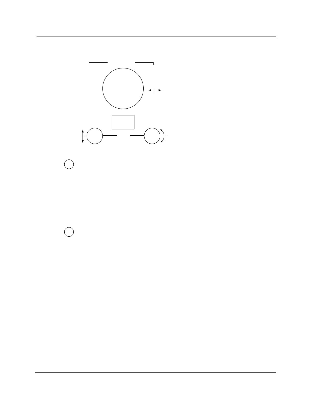
Chapter 2: Controls, Indicators, and Connectors
Cursor Controls
CURSOR
CURSOR
SELECT
LOSS
CURSOR - Turn the CURSOR knob to move the active distance cursor along the
8
displayed waveform to any point where you want a measurement. One distance
cursor is displayed in Splice Loss and Event Return Loss modes, and two in Preview,
Two Point, and Link Return Loss modes. The distance from FiberMaster’s front panel
is shown at the top of each cursor. (When two distance cursors are displayed, the
CURSOR SELECT button allows you to choose which one is active.)
In the menu system, use the CURSOR knob to select parameter values, and to enter
alphanumeric characters.
Vertical LOSS - This knob (the left-hand LOSS knob) is active in Two Point, Splice
9
Loss, Link Return Loss, and Event Return Loss modes, and allows you to adjust loss
measurements manually. Turning the vertical LOSS knob moves the active loss cursor
up and down. When you turn the knob, the active loss cursor is automatically
elongated to make manual adjustments easier in the noise (except when using LSA
slope calculation method).
To adjust a loss cursor in noise, move it until there are an equal number of noise
spikes above and below the cursor. Use the slope LOSS knob to match the cursor
slope to the signal slope.
When using the LSA slope-calculation method, the vertical LOSS knob vertically
positions the loss cursor, maintaining the same slope.
In Two Point mode (using the two-point slope-calculation method) and in Link Return
Loss mode, the active loss cursor is the one on the active distance cursor, selected
using the CURSOR SELECT button. In Splice Loss and Link Return Loss modes, there is
one distance cursor and two loss cursors. Select the active loss cursor using the
CURSOR SELECT button.
2-6 TFP2A FiberMaster User Manual
Page 69

Chapter 2: Controls, Indicators, and Connectors
10
11
Slope LOSS - This knob (the right-hand LOSS knob) is active in Two Point, Splice
Loss, Link Return Loss, and Event Return Loss modes, and allows you to rotate the
active loss cursor manually to match the slope of the signal.
When you turn the slope LOSS knob, the active loss cursor is automatically elongated
to make manual adjustments easier (except when using the LSA slope calculation
method).
When using the LSA slope calculation method, the slope LOSS knob rotates the LSA
loss cursor around the point where it touches the active distance cursor.
In Two Point mode (using the two-point slope-calculation method) and Link Return
Loss mode, the active loss cursor is the one on the active distance cursor, selected
using the CURSOR SELECT button. In Splice Loss and Event Return Loss modes, there
is one distance cursor and two loss cursors. Select the active loss cursor using the
CURSOR SELECT button.
Refer to chapter 3,
calculation used in Two Point mode.
CURSOR SELECT - Push this button to select the active cursor. You can control the
active cursor using the cursor-control knobs. The active cursor is also displayed at
higher intensity to differentiate it from the inactive cursor.
Getting Started
for information on selecting the type of slope
In Preview, Two Point, and Link Return Loss modes, which have two distance
cursors, the CURSOR SELECT button controls which of two distance cursors is active.
In Preview, Two Point, and Link Return Loss modes, the CURSOR SELECT button also
offers a “join cursors” function. Press and hold the CURSOR SELECT button to move the
inactive cursor to the same location as the active cursor.
In Splice Loss and Event Return Loss modes, there is one distance cursor and two
loss cursors. The CURSOR SELECT button selects which loss cursor is controlled by the
LOSS and SLOPE adjustment knobs. Pressing and holding the CURSOR SELECT button
in Splice Loss and Event Return Loss modes joins the loss cursors—the inactive loss
cursor is placed at the same vertical position and extends along the same slope as
the active cursor.
In both overview and expanded view, if the inactive cursor is off the screen when you
press CURSOR SELECT, the view switches to show both cursors on the screen if
possible. If the cursors are not close enough to each other to display both, the view is
centered around the new active cursor.
TFP2A FiberMaster User Manual 2-7
Page 70

Chapter 2: Controls, Indicators, and Connectors
Window Controls and Indicators
WINDOW
EXPAND
SIZE
12
13
Vertical SIZE - In overview, turn this knob to expand and contract the expansion
window vertically. In expanded view, the area defined by the expansion window fills
the waveform viewing area—in this mode turning the vertical SIZE knob expands and
contracts the waveform itself vertically.
In expanded view, dual-trace mode, the vertical SIZE knob operates on both the
current and the reference waveforms simultaneously. Each waveform expands and
contracts around the point where it intersects the active distance cursor.
Horizontal SIZE - In overview, turn this knob to expand and contract the expansion
window horizontally. In expanded view, the area defined by the expansion window
fills the waveform viewing area—in this mode turning the horizontal SIZE knob
expands and contracts the waveform itself horizontally.
If the waveform is expanded to display only 100 data points, you are prompted to
press the START/STOP button to obtain high-density data. Refer to chapter 6,
Advanced Operating Functions
density data acquisition.
In expanded view, dual-trace mode, the horizontal SIZE knob operates on both the
current and the reference waveforms simultaneously. Each waveform expands and
contracts around the point where it intersects the active distance cursor.
, for details on using the expansion window with high-
2-8 TFP2A FiberMaster User Manual
Page 71

Chapter 2: Controls, Indicators, and Connectors
14
EXPAND - Pressing this button switches between expanded view and overview
display modes. Overview displays the complete waveform as defined by the
maximum range setting, which is set on the Waveform Settings menu. The amount
of expansion displayed in expanded view is defined by the dimensions of the
expansion window, which is adjusted using the SIZE knobs, as described above. The
indicator next to the EXPAND button lights when the display is in expanded view.
If the waveform is expanded to display only 100 data points, you are prompted to
press the START/STOP button to obtain a higher sample density. Refer to chapter 6,
Advanced Operating Functions
density data acquisition.
Note: in expanded view, expanding the waveform using the SIZE knobs has the
effect of shrinking the expansion window. Shrinking the waveform in expanded view
is the same as enlarging the expansion window. The effect on the size of the
expansion window can be seen when you return to overview.
, for details on using the expansion window with high-
TFP2A FiberMaster User Manual 2-9
Page 72
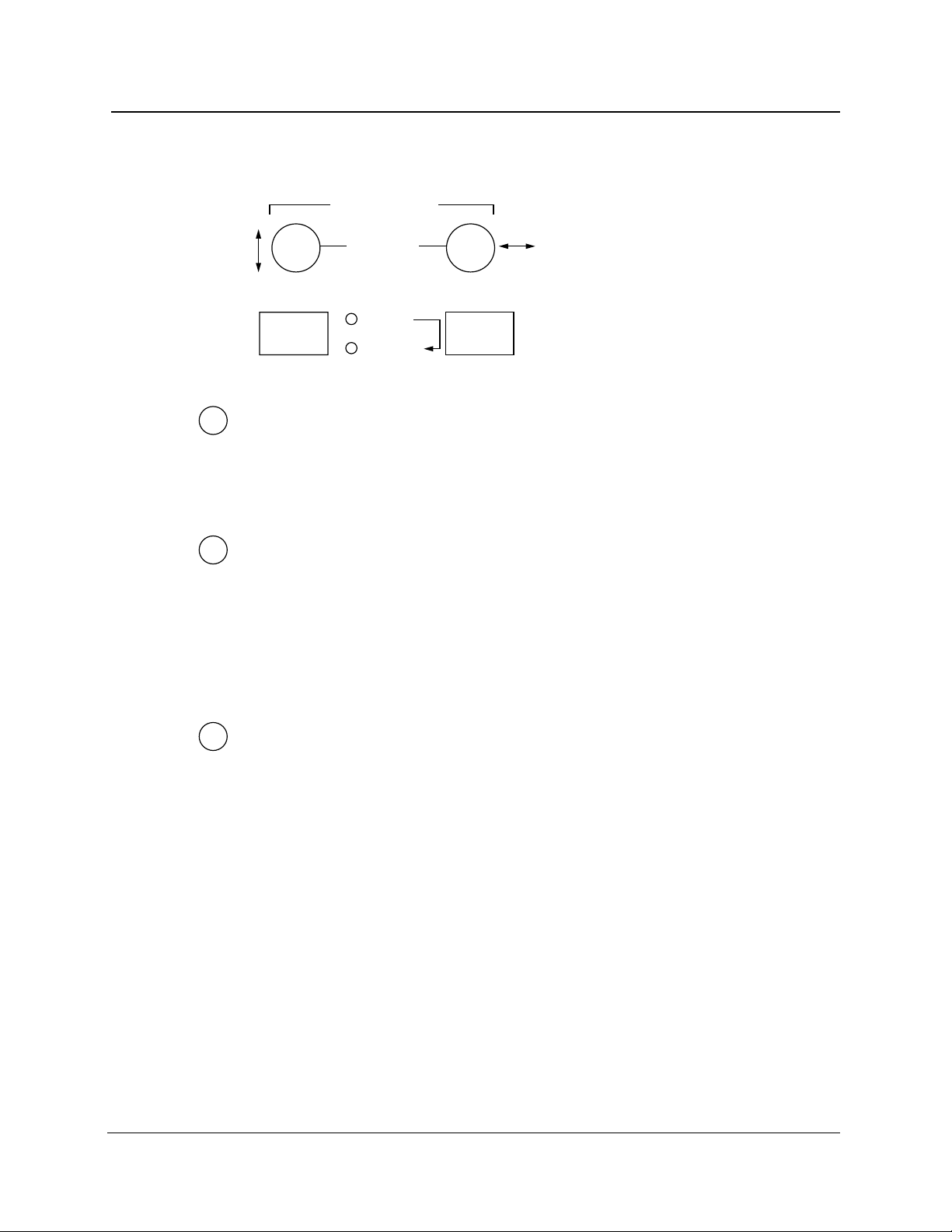
Chapter 2: Controls, Indicators, and Connectors
Waveform Controls and Indicators
WAVEFORM
POSITION
15
16
17
WFM
SELECT
CURRENT
STORE
REFERENCE
Vertical POSITION - Turn the left-hand POSITION knob to move the active waveform
up and down on the display.
When dual-trace mode is on, the vertical POSITION knob operates only on the active
waveform.
Horizontal POSITION - Turn the right-hand POSITION knob to move the active
waveform right and left on the display.
In both overview and expanded view, horizontal movement is limited to half the
maximum range in either direction.
When dual-trace mode is on, the horizontal POSITION knob operates on both the
current and the reference waveforms simultaneously.
WFM SELECT - Press this button to select which of two waveforms displays. The
two waveforms are the current acquisition from current memory, and the reference
waveform from reference memory.
When dual trace is on, both waveforms display at once. The active waveform is
highlighted, and can be moved and used for measurements. If you turn dual trace
off, the active waveform is the only one displayed. The indicator light next to the
WFM SELECT button shows which waveform is currently active.
For information on setting the dual-trace parameter, refer to chapter 3,
Started
Functions
. Details on using dual trace are given in chapter 6,
.
Advanced Operating
Getting
When dual trace is on and both the current and reference waveforms are displayed,
the dB scale is that of the active waveform. The difference between the scales of the
active and inactive waveforms is displayed at the top of the vertical scale. To align
the two waveforms vertically, press and hold the WFM SELECT button. The inactive
2-10 TFP2A FiberMaster User Manual
Page 73

Chapter 2: Controls, Indicators, and Connectors
waveform moves to the same scale as the active waveform, and the difference in the
scales displays as 0 dB.
When dual trace is off, and the view is in overview, pressing and holding the WFM
SELECT button zeros the waveform’s position—it is moved so that 0 dB is at the
bottom of the vertical scale and 0 kilometers (or kilofeet) is at the left of the horizontal
scale.
18
STORE - Press this button to store the current waveform and associated instrument
settings into reference memory. The previous contents of reference memory are
overwritten. In addition to instrument settings, the date and time the acquisition was
started, the actual elapsed acquisition time and number of averages, high-density
data, and any user-adjusted measurements are saved into reference memory.
TFP2A FiberMaster User Manual 2-11
Page 74

Chapter 2: Controls, Indicators, and Connectors
Connectors
DC power
(option 17)
AC power
RS232 GPIB
Figure 2-2. FiberMaster Rear-Panel Connectors
2-12 TFP2A FiberMaster User Manual
Page 75

Page 76

3 Getting Started
This chapter describes how to get started using the FiberMaster OTDR, including
how to display the online help available in the instrument, and how to set up the
instrument to your specifications. Power-on default settings are also listed in this
chapter.
Powering On FiberMaster and Connecting a Fiber
Turn on the instrument by pressing the POWER button. A brief initialization period
follows, during which the following sequence occurs:
1. The Tektronix logo and name of the instrument are displayed on the screen,
indicating that the display processor is working properly.
2. The display processor and the main processor perform self-tests on ROM, RAM,
and major circuits.
3. The start-up screen appears. The options installed in the instrument are listed on
the start-up screen. The instrument’s firmware version is displayed in the upper
right-hand corner. If any power-on self tests fail, the results are displayed on the
screen, and a Self Test softkey displays. This softkey allows access to a
Diagnostics menu that gives more information on the power-on test that failed.
(The Diagnostics menu is described in appendix D).
NOTE
TFP2A FiberMaster User Manual 3-1
If any power-on self tests fail, the start-up screen fails to display, or the
instrument does not power on, contact your Tektronix representative, or
telephone toll-free in the U.S. and Canada
4. Press the MODULE SELECT button to select a laser source if more than one laser
source is available on your instrument.
5. The instrument’s waveform settings are displayed at the bottom of the start-up
screen. You can change setting values from those displayed by pressing the
Change Settings softkey. Instructions on configuring your instrument are given
in this chapter. If you enter the menu system from the start-up screen, the
acquisition screen displays when you exit the menus.
6. Connect a fiber to FiberMaster in one of two ways: 1) directly, using a mating
connector plug to match the front-panel connector, or 2) indirectly via an optical
interface cable.
7. Start an acquisition by pushing the START/STOP button. When you press START/
STOP, the start-up screen is replaced by the acquisition screen.
1-800-TEK-WIDE ext. 2400
.
Page 77

Chapter 3: Getting Started
WARNING
CAUTION
Quick Start
NOTES
Figure 3-1. FiberMaster Start-Up Screen
Avoid eye exposure to laser output and open-ended fibers by covering the end or
directing the output at a non-reflective surface.
The TFP2A FiberMaster has been classified as a Class 1 laser product under the
Radiation Control and Health Safety Act of 1968.
Keep the optical output connectors and the connector plugs clean at all times.
Dust and dirt affect the optical output power. Cover the connectors when not in
use.
You can shorten the power-on process using the quick-start feature. Quick-start your
instrument by holding down the START/STOP button while you press the POWER button.
This makes the instrument to bypass power-on diagnostics, causing the start-up
screen to come up faster.
When quick-starting your instrument, release the
START/STOP
button as soon as
you see the message Starting operating system.... If you are still holding down
START/STOP
at the time the start-up screen appears, an acquisition is started
and the laser starts firing.
3-2 TFP2A FiberMaster User Manual
Page 78

Mass Storage
Chapter 3: Getting Started
Do not quick-start your instrument every time it is powered on. Allow the
instrument to run the power-on diagnostics periodically to detect any
malfunctions that might have occurred.
A Mass Storage softkey displays on the start-up screen. Press this key to go into the
mass-storage menu system, if you want to load waveform and settings files into the
instrument from floppy disk (or the optional internal RAM). You can also perform
save, delete, and format operations in the mass-storage system. Refer to chapter 7,
Mass Storage
, for instructions on how to use this system. If you enter the massstorage system from the start-up screen, the acquisition screen displays when you
exit.
TFP2A FiberMaster User Manual 3-3
Page 79

Chapter 3: Getting Started
Power-On Defaults
FiberMaster’s factory-set power-on settings are as follows:
❏ Display mode* Overview
❏ Measurement mode* Preview
❏ Wavelength Top laser in bottom module
❏ Expansion window size* 20% of screen width (limited by waveform
❏ Pulse width 850 MM = 2 m; 1300 MM = 50 m;
❏ Maximum range 850 MM = 4 km; 1300 MM = 10 km;
❏ Maximum no. of averages 20,480
❏ Refractive index 850 MM (62.5 µm core diameter) = 1.4776;
❏ Slope calculation* Two point
❏ Scattering coefficient 850 MM (62.5 µm core diameter) = -62.3;
❏ Dual trace* Off
❏ Event threshold 0.20 dB
❏ Event marking Auto
❏ Masking type Off (applicable only to FS-series 1310 nm SM
❏ Filtering On (applicable only to FL-series modules)
❏ Fiber ID* Blank
❏ Operator* Blank
❏ Fiber notes* Blank
❏ Language
❏ Display intensity Medium
❏ Display color Color
❏ Sound On
❏ Date format M/D/Y
❏ Units Metric
❏ Keyboard translation USA
❏ File format TFP2
❏ Hardcopy device Internal if printer option installed. If not,
❏ GPIB status* Online
❏ GPIB address
❏ RS232 baud rate 9600 bits per second
❏ RS232 parity None
❏ RS232 stop bits 1
❏ RS232 data bits 8
❏ RS232 flow control XON/XOFF
length) and 50% of screen height
1310 SM = 200 m; 1550 SM = 200 m
FS/FG series: 1310 SM = 50 km;
1550 SM = 50 km;
FL series: 1310 and 1550 SM = 100 km
1300 MM (62.5 µm core diameter) = 1.4719;
1310 SM = 1.4680; 1550 SM = 1.4685
1300 MM (62.5 µm core diameter) = -69.7;
1310 SM = -80.3; 1550 SM = -82.3
and 1550 nm SM modules)
1
English
RS232 Epson
2
7
3-4 TFP2A FiberMaster User Manual
Page 80

Chapter 3: Getting Started
* The settings marked with an asterisk are always reset to the initial factory-set values at power
on. For example, every time you turn on the instrument, it enters Preview mode. User-selected
power-on defaults can be defined for the remaining settings (except GPIB address) via the
User Defaults menu, described later in this chapter. Until you specify a user-defined default,
the factory default is used as the power-on default.
1
When you change languages, the newly selected language is automatically saved as the
power-on default.
2
The GPIB address is factory set to 7. The power-on default is always the value last used.
TFP2A FiberMaster User Manual 3-5
Page 81

Chapter 3: Getting Started
Using FiberMaster’s Online Help
FiberMaster’s online help system consists of pop-up windows that overlay the screen
when you press the HELP button. These windows provide brief information on the
current display.
When you are making measurements on a fiber, the current measurement mode is
described on the screen that appears when you press the HELP button. You can also
read help on how the controls function in the current mode by turning the knobs and
pushing the buttons. Each action brings up an additional help screen that describes
the function of that control.
When you are working in the menu system to configure the instrument, or to change
measurement settings, the help screens describe the operation of each parameter.
Some help screens consist of multiple pages. Turn the CURSOR knob to scroll from
page to page on mutiple-page help screens.
From any help screen, to end the help function and return to the original display,
press the HELP button again.
Figure 3-2. Sample Help Screen
3-6 TFP2A FiberMaster User Manual
Page 82

Setting up the System
FiberMaster’s operating parameters and measurement settings are controlled
through a system of menus, accessed by pressing the Change Settings softkey from
the acquisition screen. These menus and their functions are as follows:
❏ Waveform Settings menu - the Waveform Settings menu displays a series of
pop-up selection windows used to set values for operating parameters.
FiberMaster uses these settings for waveform acquisition and making
measurements. They include, for example, the maximum range, pulse width,
number of averages, slope calculation, and other settings.
❏ Operator Settings menu - allows you to enter a fiber identification string, notes,
and operator identification. This information prints with the waveform when you
press the HARD COPY button, and is saved in mass storage with the waveform or
settings file.
❏ System Settings menu - the System Settings menu displays a series of pop-up
selection windows used to set several input/output characteristics, such as
RS232 and GPIB settings, and the hardcopy device. In addition, this menu allows
you to set the language used, the system time and date, and display intensity
and color.
Chapter 3: Getting Started
❏ User Defaults menu - use this menu to set power-on defaults for the instrument
parameters that accept user-defined defaults.
❏ Remote menu - the Remote menu allows serial-port data transfers. The
operations available from this menu are to send, receive, and stop an XModem
data transfer. Status messages display on the Remote screen during data
transfers to keep you informed of operation status.
In addition to the configuration menus, if a mass-storage device or devices (floppy
disk and internal RAM) are installed in your instrument, a softkey allows access to the
Mass Storage menu system:
❏ Use the Mass Storage menu system to write and read waveform and settings
data to and from disk. This system is described in detail in chapter 7,
Storage
.
Mass
TFP2A FiberMaster User Manual 3-7
Page 83

Chapter 3: Getting Started
Entering the Menu System
To enter the menu system, from the start-up screen or from any acquisition screen,
press the Change Settings softkey. In the menus, the softkeys are redefined and
the front-panel controls function as follows:
Function Control
Print a hard copy of the screen HARD COPY
contents on the printer
(if installed).
Read online help. HELP
Select parameter value, or enter CURSOR knob
numeric and alphanumeric data.
Begin a new acquisition or start START/STOP
real-time mode without exiting
the current menu. (Waveform
Settings menu only)
Position the waveform on the POSITION knobs
display. (Waveform Settings
menu only)
NOTE
All front-panel controls besides those listed here are not functional in the menu
system.
If you are using a keyboard to enter data on FiberMaster’s configuration menus,
refer to appendix B,
Keyboard Definitions
, for a list of the key sequences that
duplicate front-panel controls. For the parameters that require character entry,
the keyboard offers additional editing functions not available via the front-panel
controls.
3-8 TFP2A FiberMaster User Manual
Page 84

Selecting Waveform Settings
Press the Change Settings softkey to enter the configuration menus. The Waveform
Settings menu screen appears, showing the first pop-up selection window, Pulse
Width. Notice that the softkeys are redefined. These keys let you move around within
the menu system, as follows:
Next Menu - go to the next menu. For example, when working on the Waveform
Settings menu, pressing the Next Menu softkey displays the Operator Settings
menu.
Next Param - go to the next pop-up selection window. For example, after setting the
pulse width, press this softkey to display the Maximum Range pop-up window. The
highlighted bar on the Waveform Settings menu moves to indicate the current
parameter.
Prev Param - go back to the previous parameter’s pop-up selection window.
Exit - return to the acquisition screen.
The Next Menu, Next Param, and Prev Param softkeys repeat when held down.
When you first enter the menu system after powering on the instrument, the Pulse
Width parameter on the Waveform Settings menu is the first pop-up selection window
displayed. If you exit the menus, then re-enter by pressing the Change Settings
softkey again, the instrument brings up the last Waveform Settings window that you
viewed before exiting the menus.
Chapter 3: Getting Started
The settings you can define on the Waveform Settings menu are:
❏ Pulse width
❏ Maximum range
❏ Maximum number of averages
❏ Refractive index
❏ Slope calculation
❏ Scattering coefficient
❏ Dual trace
❏ Event threshold
❏ Event marking mode
❏ Masking type and manual masks (if supported by the laser source—FS-series
1310 nm SM and 1550 nm SM)
❏ Software filtering (available only when an FL-series module is selected)
TFP2A FiberMaster User Manual 3-9
Page 85

Chapter 3: Getting Started
Pulse Width
Press the Change Settings softkey to enter the menu system. When you initially
enter the menu system after power-on, the first Waveform Settings pop-up selection
window, Pulse Width, displays. If the Pulse Width window is not displayed upon
entering the menu system, press Next Param or Prev Param until the pulse-width
parameter is highlighted on the Waveform Settings menu.
Figure 3-3. Pulse Width Pop-Up Selection Window,
Waveform Settings Menu
The pulse width is the length of time the laser is on during each sampling acquisition,
also measured in distance units. (A sampling acquisition is the acquisition of one set
of data points on the waveform.) The current pulse-width setting is highlighted in the
window. The number of pulse-width selections is defined by the laser source
selected, and may change when the laser source is changed.
Pulse-width selections are also dependent on the current maximum-range setting,
and vice versa. Because the two parameters are interdependent, the Maximum
Range pop-up window displays next to the Pulse Width window to show the
maximum-range settings that are available with the current pulse-width selection. If
you change the pulse width and the current maximum-range selection is unavailable
for the new pulse width, the closest available maximum-range setting is automatically
selected.
Short pulse widths permit more detail to be seen over a shorter range. Use long pulse
widths when you want to see more fiber, at lower resolution. The default pulse width
3-10 TFP2A FiberMaster User Manual
Page 86

Chapter 3: Getting Started
depends on the laser source selected: 2 meters for 850 nm MM, 50 meters for 1300
nm MM, and 200 meters for the singlemode lasers.
For the FM- and FS-series optical modules, the 1300 MM, 1310 SM, and 1550 SM
modules have three high-resolution pulse widths available. They are 10 ns, 20 ns,
and 50 ns pulse widths, denoted as high resolution on the menu by [HR]. These
pulse widths offer increased distance measurement accuracy at short ranges.
Change the pulse width by turning the CURSOR knob to highlight your selection. If you
have a keyboard, you can use the cursor keys to do this.
The selection of a new pulse width requires a new acquisition in order to take effect.
When you press the Next Param, Prev Param, Next Menu, or Exit softkey to exit
the Pulse Width parameter, the pulse-width setting at the bottom of the screen is
highlighted to indicate that the current setting does not match acquisition data. When
you exit the menu system, the following message displays:
Press START/STOP
to acquire
new data.
NOTE
Press START/STOP to start an acquisition using the new pulse width. The highlighting
is cleared when new data is acquired, because the pulse-width setting now
corresponds to the displayed waveform data. You can press START/STOP to start a
new acquisition without exiting the menu system.
You may notice that the acquisition range shifts when you change pulse widths. If
you change from a long to a short pulse width, the range of the new acquisition
may not extend from the start of the current range to the location of the active
distance cursor. In this case, the new acquisition is centered around the active
distance cursor.
TFP2A FiberMaster User Manual 3-11
Page 87

Chapter 3: Getting Started
Maximum Range
To display the Maximum Range pop-up window, from the acquisition screen press
Change Settings, then press Next Param or Prev Param until the maximum-range
parameter is highlighted on the Waveform Settings menu.
Figure 3-4. Maximum Range Pop-Up Selection Window,
Waveform Settings Menu
Use the Maximum Range selection window to specify the maximum distance over
which data may be acquired. The maximum range chosen is displayed as the full
width of the overview acquisition screen. The available range settings are determined
by the laser source you selected. This distance represents the maximum range that
the acquisition can be moved down the fiber, and usually is set to the length of the
fiber.
NOTE
Set the maximum range at least as long as the fiber under test, to avoid
ghosting. A ghost is a reflection received from the previous sampling acquisition,
caused by an event on the fiber past the end of the maximum range. The light
reflected from such an event reaches the instrument’s detector during the
following sampling acquisition, and the reflection is averaged into the valid
waveform data within the maximum range. When event marking is on, any
ghosts on the waveform are marked and measured as events.
3-12 TFP2A FiberMaster User Manual
Page 88

Chapter 3: Getting Started
The range selections change when you select a new laser source. The default
maximum range depends on the laser source selected:
❏ 4 km for 850 nm MM
❏ 10 km for 1300 nm MM
❏ 50 km for 1310 and 1550 nm SM, FS-series modules
❏ 100 km for 1310 and 1550 nm SM, FL-series modules
The maximum-range selections are also dependent on the current pulse-width
setting, and vice versa. Because these two parameters are interdependent, the Pulse
Width pop-up window displays next to the Maximum Range window to show the
pulse-width settings that are available with the current maximum-range selection. If
you change the maximum range, and the current pulse width is unavailable for the
new range, the closest available pulse-width setting is automatically selected.
Change the maximum-range setting by turning the CURSOR knob to highlight your
selection. If you have a keyboard, you can use the cursor keys to do this.
Spacing between data points changes for the longest maximum range settings. When
the maximum range is set to 160 km or less, data points are spaced up to 10 meters
apart. For maximum ranges of 200 km and above, the spacing between data points is
20 meters.
The selection of a new maximum range requires a new acquisition in order to take
effect. When you press the Next Param, Prev Param, Next Menu, or Exit softkey to
exit the Maximum Range parameter, the maximum-range setting at the bottom of the
screen is highlighted to indicate that the current setting does not match acquisition
data. When you exit the menu system, the following message displays:
Press START/STOP
to acquire
new data.
Press START/STOP to start an acquisition using the new maximum range. The
highlighting is cleared when new data is acquired, because the maximum-range
setting now corresponds to the displayed waveform data. You can press START/STOP
to start a new acquisition without exiting the menu system.
TFP2A FiberMaster User Manual 3-13
Page 89
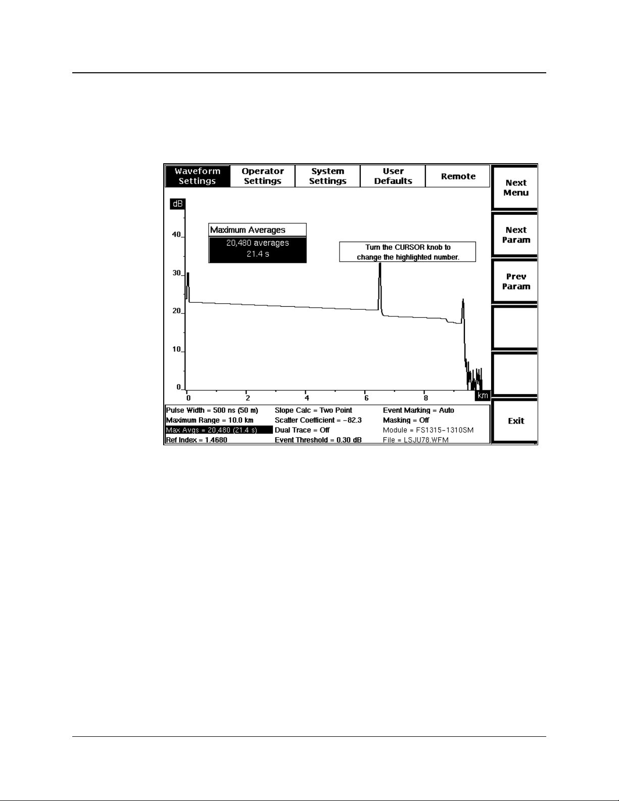
Chapter 3: Getting Started
Maximum Averages
To display the Maximum Averages pop-up window, from the acquisition screen press
Change Settings, then press Next Param or Prev Param until the maximumaverages parameter is highlighted on the Waveform Settings menu.
Figure 3-5. Maximum Averages Pop-Up Selection Window,
Waveform Settings Menu
Use the Maximum Averages window to set the number of sampling acquisitions the
instrument averages before stopping an acquisition. A sampling acquisition is the
acquisition of one set of data points on the waveform, and is the same as the
waveform data that would be acquired if you set the number of averages to 1.
Higher averages produce better signal to noise, but take longer to complete an
acquisition. Lower averages result in faster acquisitions, but typically include more
noise.
The approximate length of time required for the number of averages you select is
also displayed on the menu. The time for a certain number of averages will vary,
depending on the pulse-width, maximum-range, and masking-type settings. The
characteristics of the fiber under test also affect the time it takes to acquire and
process the waveform data.
The maximum number of averages possible is 16,777,216. The minimum is 256.
The factory-default number of averages is 20,480. You can change the power-on
default using the User Defaults menu, described later in this chapter.
3-14 TFP2A FiberMaster User Manual
Page 90

Chapter 3: Getting Started
NOTE
The time shown is for normal-density data; a high-density acquisition would take
approximately three to five times longer.
Select the number of averages using the CURSOR knob. Turning the knob clockwise
increases the number in minimum increments of 256. Turning the knob
counterclockwise decreases the number. If you have the optional keyboard, you can
use the cursor keys to do this.
The new setting is saved when you exit the Maximum Averages window by pressing
one of the Next Param, Prev Param, Next Menu, or Exit softkeys. If the number of
averages for an acquisition in progress is greater than the new setting, the acquisition
stops. Otherwise, acquisition continues until the new maximum number of averages
is reached. If no acquisition is in progress, the new setting takes effect with the next
acquisition.
On the acquisition screen, the actual number of averages and the elapsed acquisition
time are shown at the top of the screen. These numbers are saved with the waveform
when it is written to reference memory or mass storage.
TFP2A FiberMaster User Manual 3-15
Page 91

Chapter 3: Getting Started
Refractive Index
To display the Refractive Index pop-up window, from the acquisition screen press
Change Settings, then press Next Param or Prev Param until the refractive-index
parameter is highlighted on the Waveform Settings menu.
Figure 3-6. Refractive Index Pop-Up Selection Window,
Waveform Settings Menu
Use the Refractive Index window to specify the refractive index of the fiber under test.
You can set the refractive index to any value from 1.4000 to 1.6000, inclusive. This
value is characteristic of the fiber, and can vary from fiber to fiber. The refractive
index can be obtained from the fiber manufacturer. The factory-default refractive
index values depend on the laser source as follows:
❏ 850 nm MM - 1.4776
❏ 1300 nm MM - 1.4719
❏ 1310 nm SM - 1.4680
❏ 1550 nm SM - 1.4685
You can set a different power-on refractive index for the currently selected laser
source using the User Defaults menu, described later in this chapter.
Turn the CURSOR knob to increase and decrease the refractive index, in increments of
the least significant digit (ten thousandths). You can also use the optional keyboard
to enter the refractive index. As you type in digits from the keyboard, they are shifted
to the left.
3-16 TFP2A FiberMaster User Manual
Page 92

A change to the refractive index affects the distance scale and measurements. The
new refractive index setting takes effect immediately, rescaling the distance
measurements as you adjust the refractive index value.
Calibrating the Refractive Index
If you do not know the refractive index of the fiber under test, you can calibrate the
index using a known length of fiber, or a known distance to a fiber feature. To do this,
on the acquisition screen, place the active distance cursor at the end of the fiber or
on the feature. Enter the Waveform Settings menu, and display the Refractive Index
window. Adjust the refractive index. As the index changes, the distance
measurement is rescaled. When the distance measurement matches the known
distance to the fiber feature, the refractive index setting is correct.
Chapter 3: Getting Started
TFP2A FiberMaster User Manual 3-17
Page 93

Chapter 3: Getting Started
Slope Calculation
To display the Slope Calculation pop-up window, from the acquisition screen press
Change Settings, then press Next Param or Prev Param until the slope-calculation
parameter is highlighted on the Waveform Settings menu.
Figure 3-7. Slope Calculation Pop-Up Selection Window,
Waveform Settings Menu
Use the Slope Calculation window to select the type of slope (loss per distance unit)
calculation done in Two Point Mode. The Two Point slope setting calculates the
average slope using the two-point loss and two-point distance values. The LSA
setting fits a straight line to the data between two distance cursors using the least
squares average (LSA) algorithm.
NOTE Use the LSA slope calculation method for measuring fiber loss on featureless
sections of backscatter, and the two-point method for most other two-point
measurements.
Change the slope calculation by turning the CURSOR knob to highlight your selection.
If you have a keyboard, you can use the cursor keys to do this.
The new slope calculation takes effect when you exit the parameter by pressing one
of the Next Param, Prev Param, Next Menu, or Exit softkeys. If the instrument was
in Two Point mode before you entered the menu system, and there were no previous
manual adjustments to two-point measurements, the slope is recalculated using the
new method.
3-18 TFP2A FiberMaster User Manual
Page 94

Chapter 3: Getting Started
If two-point measurements included manual adjustments, the method of slope
calculation changes, but the slope is not recalculated. The new loss cursor(s) are
fitted to the existing points where the old loss cursor(s) intersected the distance
cursors. In this case, you can restart two-point measurements using the new method
by pressing the Two Point softkey.
TFP2A FiberMaster User Manual 3-19
Page 95

Chapter 3: Getting Started
Scattering Coefficient
To display the Scattering Coefficient pop-up window, from the acquisition screen
press Change Settings, then press Next Param or Prev Param until the scatteringcoefficient parameter is highlighted on the Waveform Settings menu.
Figure 3-8. Scattering Coefficient Pop-Up Selection Window,
Waveform Settings Menu
The scattering coefficient represents the amount of backscatter reflected by a
particular fiber. Use the scattering coefficient to account for differences between
fibers, for more accurate return-loss measurements. The scattering coefficient is a
characteristic of the fiber under test and, similar to the refractive index, can vary from
fiber to fiber. It is a negative number indicating the dB level of the backscattered light
relative to the light entering the fiber.
NOTE
The scattering-coefficient setting applies only to return-loss measurements, and
has no effect on measurements in any of the other modes.
The scattering coefficient is based on a pulse width of 1 nanosecond, and is
automatically adjusted to correspond to the pulse width used in acquiring the
waveform being measured.
Use the Scattering Coefficient window to specify the scattering coefficient of the fiber
under test. You can set this number to any value from -100 to -40 dB, inclusive. Turn
the CURSOR knob to increase and decrease the scattering coefficient, in increments of
the least significant digit, one-tenth dB. You can also use the optional keyboard to
3-20 TFP2A FiberMaster User Manual
Page 96

Chapter 3: Getting Started
enter the scattering coefficient. As you type in digits from the keyboard, they are
shifted to the left.
The scattering coefficient for a particular fiber can usually be obtained from the fiber
manufacturer. If you do not know the scattering coefficient, however, it is
recommended that you use the factory-default values, which depend on the laser
source as follows:
❏ 850 nm MM (62.5 µm core diameter) = -62.3 dB
❏ 1300 nm MM (62.5 µm core diameter) = -69.7 dB
❏ 1310 nm SM = -80.3 dB
❏ 1550 nm SM = -82.3 dB
If you do not know the scattering coefficient of a particular fiber, but the fiber includes
a reflection for which the return loss is known, you can adjust the scattering
coefficient by performing an event return-loss measurement on the reflection and
adjusting the scattering coefficient until the return-loss value is correct.
When comparing a return-loss measurement to any previous return-loss
measurements made on the same event, be sure to use the same scattering
coefficient value that was used for the previous measurement.
You can set a different power-on scattering coefficient for the currently selected laser
source using the User Defaults menu, described later in this chapter.
TFP2A FiberMaster User Manual 3-21
Page 97

Chapter 3: Getting Started
Dual Trace
To display the Dual Trace pop-up window, from the acquisition screen press Change
Settings, then press Next Param or Prev Param until the dual-trace parameter is
highlighted on the Waveform Settings menu.
Figure 3-9. Dual Trace Pop-Up Selection Window,
Waveform Settings Menu
Use the Dual Trace window to turn dual-trace mode on and off. When dual trace is
on, both the current waveform and the reference waveform are displayed at the same
time. The active waveform is displayed at a brighter intensity than the inactive
waveform. When dual trace is off, the active waveform (selected using the WFM
SELECT button on the front panel) is the only trace displayed. The default dual-trace
setting is off.
Turn dual trace on or off by turning the CURSOR knob to highlight your selection. If you
have a keyboard, you can use the cursor keys to do this.
The new display mode takes effect when you exit the dual-trace parameter by
pressing one of the Next Param, Prev Param, Next Menu, or Exit softkeys.
Using dual-trace mode is discussed in more detail in chapter 6,
Functions
3-22 TFP2A FiberMaster User Manual
.
Advanced Operating
Page 98
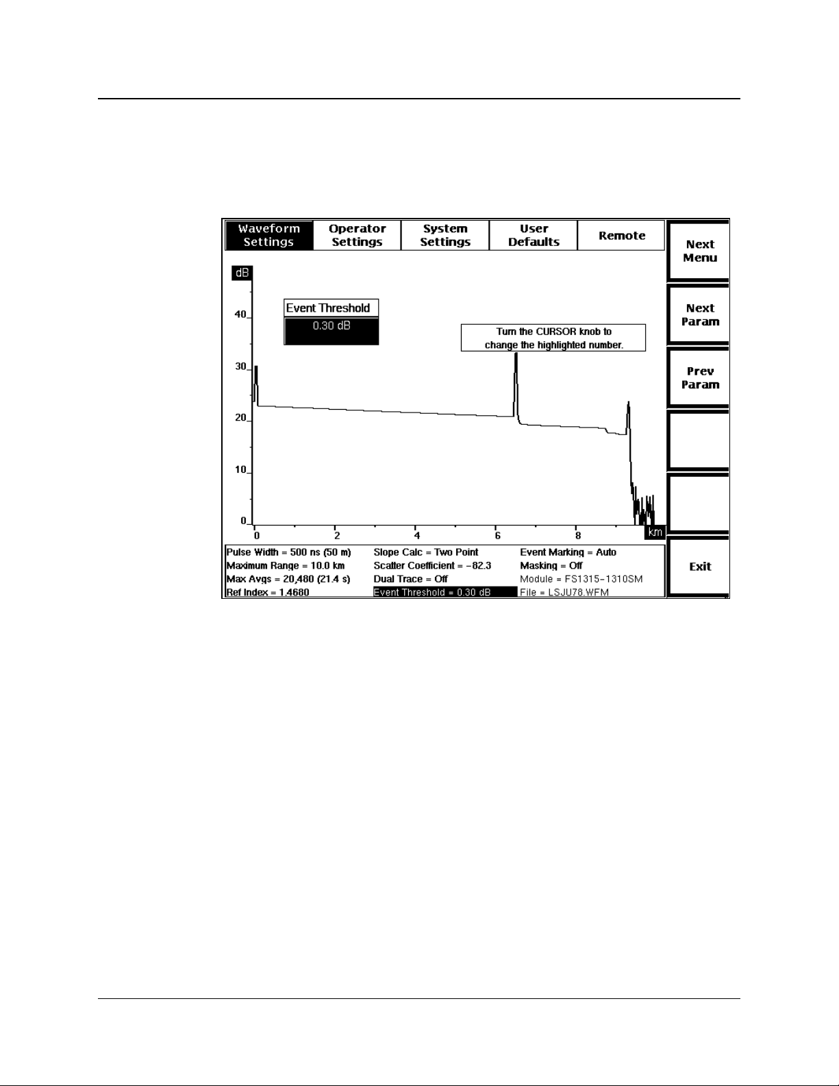
Event Threshold
Chapter 3: Getting Started
To display the Event Threshold pop-up window, from the acquisition screen press
Change Settings, then press Next Param or Prev Param until the event-threshold
parameter is highlighted on the Waveform Settings menu.
Figure 3-10. Event Threshold Pop-Up Selection Window,
Waveform Settings Menu
Use the Event Threshold window to set the threshold for events that are marked
when Event Marking mode is on. Only those events with splice-loss measurements
that meet or exceed the threshold are included, both on the acquisition screen and on
the event table.
The factory-default event threshold is 0.20 dB. You can set a different power-on
event threshold using the User Defaults menu, described later in this chapter.
Turn the CURSOR knob clockwise or counterclockwise to increase or decrease the
event threshold. The value changes in increments of one one-hundredth of a dB
between 0.03 and 0.20 dB, then by five one-hundredths to a maximum value of 5.00
dB.
TFP2A FiberMaster User Manual 3-23
Page 99

Chapter 3: Getting Started
Event threshold minimums depend on the currently selected pulse width, as follows:
NOTE
Pulse Width
(meters)
Event Threshold
Minimum (dB)
>400 .07
200 to 400 .05
<200 .03
Although the event threshold can be set to .03 dB, for pulse widths 200 meters or
longer, the minimum threshold used is actually .05 or .07 dB.
The new setting is saved when you exit the Event Threshold window by pressing one
of the Next Param, Prev Param, Next Menu, or Exit softkeys. All events with splice
losses that meet or exceed the new threshold are displayed, including both
automatically and manually marked events.
If the new threshold is lower than the previous setting, additional event markers may
be displayed on the acquisition screen and on the event table. If the new threshold is
higher than the previous setting, event markers may be deleted from the acquisition
screen and the event table when the new setting takes effect. In these cases, the
displayed events are also renumbered.
All marked events are displayed on the Place Event Markers screen, regardless
of the event-threshold setting. The Place Event Markers screen is accessible
from the Event Marking parameter window when event marking is set to Manual.
In addition, all manually placed event markers are displayed regardless of the
event-threshold setting, both on the acquisition screen and in the event table.
For information on using event marking and the Place Event Markers screen, refer to
chapter 5,
Event Marking
.
3-24 TFP2A FiberMaster User Manual
Page 100

Event Marking
Chapter 3: Getting Started
To display the Event Marking pop-up window, from the acquisition screen press
Change Settings, then press Next Param or Prev Param until the event-marking
parameter is highlighted on the Waveform Settings menu.
Figure 3-11. Event Marking Pop-Up Selection Window,
Waveform Settings Menu
Use the Event Marking window to choose whether events on a fiber under test are
automatically marked. The factory-default event-marking setting is Auto. You can
use the User Defaults menu, described later in this chapter, to choose a different
power-on default.
When event marking is set to Auto, all events with splice-loss measurements that
meet or exceed the event threshold are automatically marked and measured on the
acquisition screen and the measurements used to compile the event table. Event
markers are recalculated and redisplayed with each new acquisition.
The Manual setting allows you to set and adjust the event markers using the Place
Event Markers screen. When the manual setting is selected, an additional softkey
displays on the Waveform Settings menu, Place Markers. This softkey gives you
direct access to the Place Event Markers screen, where you can add, move, and
delete event markers manually.
The Manual setting prevents the system from automatically locating events, but does
not delete any existing markers. The markers indicate where measurements are
recalculated for the event table with each new acquisition. If the new splice-loss
TFP2A FiberMaster User Manual 3-25
 Loading...