


ZZZ
xx
TEK-USB-488
GPIB to USB Adapter
User Manual
*P071183902*
071-1839-02


xx
ZZZ
TEK-USB-488
GPIB to USB Adapter
User Manual
www.tektronix.com
071-1839-02

Copyright © Tektronix. All rights re
owned by Tektronix or its subsidiaries or suppliers, and are protected by national
copyright laws and international treaty provisions.
Tektronix products are covered by U.S. and foreign patents, issued and pendin g.
Information in this publication supersedes that in all previously published
material. Specifications and p
TEKTRONIX and TEK are registered trademarks of Tektronix, Inc.
served. Licensed software products are
rice change privileges reserved.
Contacting Tektronix
Tektronix, Inc.
14200 SW Karl Braun Drive
P.O. Box 500
Beaverton, OR 97077
USA
For pro duct information, sales, service, and technical support:
In North Am erica, call 1-800-833-9200.
Worldwide, visit www.tektronix.com to find contacts in your area.

Table of Contents
Warranty.................................. ................................. 1
General Safety Summary .................. .............................. 3
Compliance Information .............................................. ... 5
EMC Compliance ...... ............................................. 5
Safety Compliance ............................................ ...... 6
Environmental Considerations ..................................... 8
Preface................................. .................................... 9
Key Features ............................................. ............ 9
Installation ................... ........................................... 10
Standard Accessories ........ ..................................... 10
Optional Accessories.............................................. 10
Controls and Connectors........... ............................... 11
Connecting Power................................................. 12
Connecting Cables ................................... ............. 14
Setting the GPIB Address ........................................ 15
Updating Firmware............................................... . 17
Mounting the Adapter............................. ................ 19
Troubleshooting . ................................................... .... 20
Specifications ........................................ ................... 23
保証................................................................ 25
安全にご使用いただくために .................................... 27
適合性に関する情報 ............................................. 29
EMC ....................................... ......................... 29
安全性 ........................................................ 30
環境条件について ........................................... 32
まえがき............................................................ 33
主な特長 ...................................................... 33
設置 ...................................... ............................... 34
スタンダード・アクセサリ ...................................... 34
オプショナル・アクセサリ ..................................... 34
コントロールおよびコネクタ .................................. 35
の接続 ................................................... 36
電源
TEK-USB-488 GPIB to USB Adapter User Manual i

Table of Contents
ケーブルの接続 .............................................. 38
GPIB アドレスの設定 ......................................... 39
ファームウェアの更新 ........................................ 41
アダプタの設置 ............................................... 43
トラブルシューティング ............................................ 44
仕様................................................................ 49
保修................................................................ 51
常规安全概要 ..................................................... 52
符合性信息........................................................ 54
EMC 符合性 ................................................... 54
安全符合性 ................................................... 55
环境注意事项 ................................................ 56
前言................................................................ 57
主要功能...................................................... 57
安装................................................................ 58
标准附件...................................................... 58
可选附件...................................................... 58
控件和连接器 ................................................ 59
连接电源...................................................... 59
连接电缆...................................................... 62
设置 GPIB 地址 .............................................. 63
更新固件...................................................... 64
安装适配器 ................................................... 66
故障排除 .......................................................... 67
技术指标 .......................................................... 70
ii TEK-USB-488 GPIB to USB Adapter User Manual

Warranty
Tektronix warrants that this product will be free from de fects in
materials and workmanship for a period of one (1) year from the date
of shipm ent. If any such product proves defective during this warranty
period, Tektronix, at its option, either will repair the defective product
without charge for parts and labor, or will provide a replacement in
exchange for the defective product. Parts, modules and replacement
products used by Tektronix for warranty work may be new or
reconditioned to like new performance. All replaced parts, modules and
products become the property of Tektronix.
In order to obtain service under this warranty, Customer m ust notify
Tektronix of the defect before the expiration of the warranty period and
make suitable arrangements for the performance of service. Customer
shall be responsible for packaging and shipping the defective product
to the service center designated by Tektronix, with shipping charges
prepaid. Tektronix shall pay for the retu rn of the product to Customer if
the shipment is to a location within the country in which the Tektronix
service center is located. Customer shall be responsible for paying all
shipping charges, duties, taxes, and any other ch arges for products
returned to any other locations.
This w arranty shall not apply to any defect, failure or damage caused
by improper use or improper or inadequate maintenance and care.
Tektronix shall not be obligated to furnish service under this warranty
a) to repair damage resulting from attempts by personnel o ther than
Tektronix representatives to install, repair or service the product;
b) to repair damage resulting from improper use or connection to
incompatible equipment; c) to repair any damage or malfunction caused
by the use of non-Tektronix supplies; or d) to service a product that has
been modified or integrated with other products when the effect of such
modification or integration increases the time or difficulty of servicing
the product.
THIS WARRANTY IS GIVEN BY TEKTR ONI X WITH
RESPECT TO THE PRODUCT IN LIEU OF ANY OTHER
WARRANTIES, EXPRESS OR IMPLIED. TEKTRONIX AND
ITS VENDORS DISCLAIM ANY IMPLIED WARRANTIES OF
MERCHANTABILITY OR FITNESS FOR A PARTICULAR
PURPOSE. TEKTRONIX’ RESPONSIBILITY TO REPAIR
TEK-USB-488 GPIB to USB Adapter User Manual 1

Warranty
OR REPLACE DEFECTIVE PRODUCTS IS THE SOLE AND
EXCLUSIVE REMEDY PROVIDED TO THE CUSTOMER
FOR BREACH OF THIS WARRANTY. TEKTRONIX AND ITS
VENDORS WILL NOT BE LIABLE FOR ANY INDIRECT,
SPECIAL, INCIDENTAL, OR CONSEQUENTIAL DAMAGES
IRRESPECTIVE OF WHETHER TEKTRONIX OR THE VENDOR
HAS ADVAN CE NOTICE OF THE POSSIBILITY OF SUCH
DAMAGES.
[W2–15AUG04]
2 TEK -USB-488 GPIB to USB Adapter User M anual

General Safety Summary
Review the follow ing safety precautions to avoid injury and prevent
damage to this product or any products connected to it.
To avoid potential hazards, use this product only as specified.
Only qualified personnel should perform service procedures.
To Avoid Fire or Personal Injury
Use Proper Power Cord. Use only the power cord specified for this
product and certified for the country of use.
Observe All Terminal Ratings. To a v oid fire or shock hazard, observe all
ratings and markings on the product. Consult the product manual for
further ratings information before making connections to the product.
Do Not Operate Without Covers. Do not operate this product with covers
or panels removed.
Do Not Operate With Suspected Failures. If you suspect that there is
damage to this product, have it inspected by qualified service personnel.
General Safety Summary
Avoid Exposed Circuitry. Do not touch exposed connections and
components when power is present.
Use Proper AC A dapter. Use only the AC adapter specified for this
product.
Wear Eye Protection. Wear eye prote
rays or laser radiation exists.
Do Not Operate in Wet/Damp Conditions.
Do Not Operate in an Explosive Atmosphere.
Keep Product Surfaces Clean and Dry.
Provide Proper Ventilation.
for details on installing t he product so it has proper ventilation.
TEK-USB-488 GPIB to USB Adapter User Manual 3
Refer to the manual’s installation instructions
ction if exposure to high-intensity

General Safety Summary
Terms in this Manual
These terms may appear in this manual:
WARNING. Warning statements identify conditions or practices that could
result in injury or loss of life.
CAUTION. Caution statemen ts identify conditions or practices that could
result in damage to this product or other property.
Symbols and Terms on the Product
These terms may appear on the product:
DANGER indicates an injury hazard immediately accessible as you
read the marking.
WARNING indicates an injury hazard not imm ediately accessible
as you read the marking.
CAUTION indicates a hazard to property including the product.
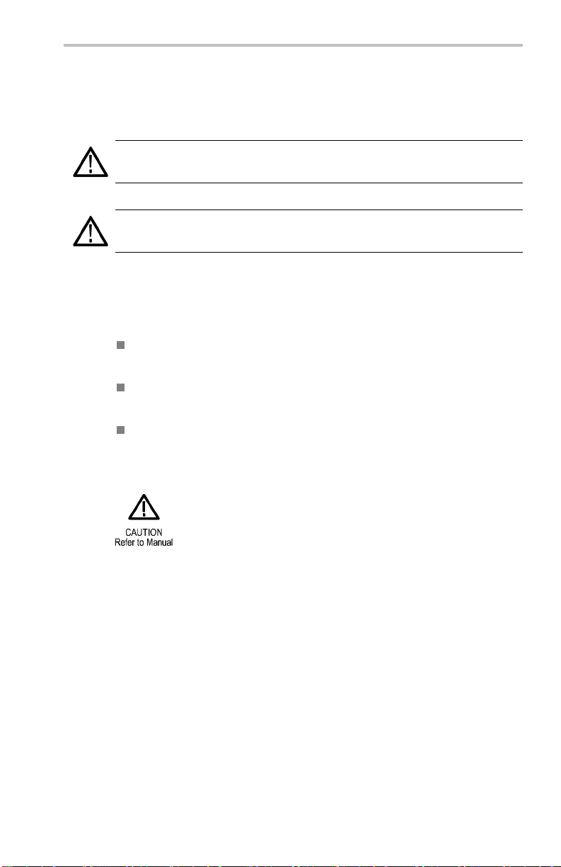
The follow ing symbol(s) may appear on the product:
4 TEK -USB-488 GPIB to USB Adapter User M anual

Compliance Information
This section lists the EMC (electromagnetic compliance) and
environmental standards with which the instrument complies.
EMC Compliance
EC Declaration of Conformity – EMC
Meets intent of Directive 2004/108/EC for Electromagnetic
Compatibility. Compliance was demonstrated to the following
specifications as listed in the Official Journal of the European
Communities:
Compliance Information
EN 61326-1 2006. EMC requirements for electrical equipment for
measurement, control, and laboratory use.
123
CISPR 11:2003. Radiated an d cond ucted emission s, G roup 1,
Class A
IEC 610 00-4-2:2 001 . Electrostatic discharge immunity
IEC 6100 0-4-3 :20 02. RF electromagnetic field immunity
IEC 61000-4-4:2 004 . Electrical fast transient / burst immunity
IEC 6 100 0-4-5 :20 01. Power line surge immunity
IEC 61000-4-6:2003. C o ndu cted RF immunity
IEC 61000-4-11:2004. Voltage dips and interruptions immunity
EN 61000-3-2:2006. AC power line harmonic emissions
EN 61000-3-3:1995. Voltage changes, fluctuations, and flicker
1
This product is intended for use in nonresidential areas only. Use in residential areas
may cause electromagnetic interference.
2
Emissions which exceed the levels required by this standard may occur when this
equipment is connected to a test object.
3
To ensure compliance with the EMC standards listed here, high quality shielded interface
cables should be used.
TEK-USB-488 GPIB to USB Adapter User Manual 5

Compliance Information
European Contact.
Tektronix UK, Ltd.
Western Peninsula
West e r n Road
Bracknell, RG12 1RF
United Kingdom
Australia / New Zealand Declaration of Conformity – EMC
Complies with the EMC provision of the Radiocommunications Act per
the following standard, in accordance with ACMA:
CISPR 11:2003. Radiated and Conducted Emissions, Group 1,
Class A, in accordance with EN 61326-1:2006.
Safety Compliance
Equipment Type
Test and measuring equipment.
Pollution Degree Description
A measure of the contaminants that could occur in the environment
around and within a prod uct. Typically the internal environment inside
a product is considered to be the same as the external. Products should
be used only in the environment for which they are rated.
Pollution Degree 1. No pollution or only dry, nonconductive
pollution occurs. Products in this category are generally
encapsulated, hermetically sealed, or located in clean rooms.
Pollution Degree 2. Normally only dry, no nconductive pollution
occurs. Occasionally a temporary conductivity that is caused
by condensation must be expected. This location is a typical
office/home environment. Temporary condensation occurs only
when the p roduct is out of service.
6 TEK -USB-488 GPIB to USB Adapter User M anual

Compliance Information
Pollution Degree 3. Co nductive pollution, or dry, nonco nductive
pollution that becomes conductive due to condensation . These
are sheltered locations w here neither temperature nor humidity
is controlled. The area is protected from direct sunshine, rain, or
direct wind.
Pollution Degree 4. Pollution that generates persistent con ductivity
through conductive dust, rain, or snow. Typical outdoor locations.
Pollution Degree
Pollution Degree 2 (as defined in IEC 61010-1). Note: Rated for indoor
use only.
TEK-USB-488 GPIB to USB Adapter User Manual 7

Compliance Information
Environmental Considerations
This section provides information about the environmen tal impact of
the product.
Product End-of-Life Handling
Observe the following guidelines when recycling an instrument or
component:
Equipment Recycling. Production of this equipment required the
extraction and use of natural resources. The equipment may contain
substances that could b
if improperly handled at the product’s end of l ife. In order to avoid
release of such substances into the environment and to reduce the use
of natural resources
appropriate system that will ensure that most of the materials are reused
or recycled appropriately.
e harm ful to the environment or human health
, we encourage you to recycle this product in an
This symbol indica
applicable Europ
Directives 2002
electronic equi
about recyclin
the Tektronix
tes that this product complies with the
ean Union requirements according to
/96/EC and 2006/66/EC on waste electrical and
pment (WEEE) and batteries. For information
g options, check the Support/Service section of
Website(www.tektronix.com).
Restriction of Hazardous Substances
This product has been classified as Monitoring and Control equipment,
and is outside the scope of the 2002/9 5/EC RoHS Directive.
8 TEK -USB-488 GPIB to USB Adapter User M anual

Preface
This manual describes the installation and operation of the
TEK-USB-488 GPIB to USB Adapter. The adapter allows you to
connect a USB device port on your USBTMC-USB488 compliant
instrument, such as a DPO4000 Series oscilloscope, to a GPIB
(IEEE488) controller.
Controller GPIB Adapter USB Instrument
Key Features
Key features include:
Preface
GPIB control of USBTMC-USB488 compliant Tektronix
instruments through the USB port. The USBTMC protocol enables
USB devices to communicate using IEEE488 style messages. This
lets you run your GPIB software applications on USB hardware.
Fast data transfer rates
Power from either the USB host or an optional external power
supply
TEK-USB-488 GPIB to USB Adapter User Manual 9

Installation
Installation
Unpack the adapter and check tha
listed as standard accessories. Check the Tektronix Web site
(www.tektronix.com) for the most current information.
Standard Accessories
Description Part number
User Manual 071-1839-XX
USB cable (2 each, 1 meter)
Optional Accessories
Description Part number
GPIB cable (1 meter)
GPIB cable (2 meter)
External power supply (order power
cord separately)
United States power cord
Universal European power cord 161-0066-XX
United Kingdom power cord 161-0066-XX
Australia power cord 161-0066-XX
Switzerland power cord
Japan power cord 161-0342-XX
China power cord
India/South Africa power co rd
t you received all the items
174-4401-XX
012-0991-XX
012-0991-XX
119-8724-XX
161-0066-XX
161-0154-XX
161-0304-XX
161-0400-XX
10 TEK-USB-488 GPIB to USB Adapter User Manual

Controls and Connectors
1. GPIB Connector
2. Adapter Status indicator (See Table 1 on page 22.)
Installation
3. USB Status indicator (See Table 2 on page 22.)
4. USB Host port for connection to the USB Device port on the
controlled instrument.
5. USB Device port. A USB host can provide power to the adapter via
this port. This port is for power only. No USB device functionality
is provided.
6. Power Connector. For use with the optional external power supply,
Tektronix part number 119-8724-XX.
7. Power indicator. Lighted when power is applied.
TEK-USB-488 GPIB to USB Adapter User Manual 11

Installation
Connecting Power
You can connect power to the adapter in one of two ways:
From a USB host port
From the optional external power supply
Connecting USB Power
To apply power to your adapter from a USB host port, do the following
procedure:
1. Connect the device end of a USB cable to the USB Device port
on the rear panel of the adapter.
2. Connect the host end of the USB cable to a USB Host port on the
equipment that is to provide power (typically the instrument being
controlled or a PC).
3. Verify that the Power LED lights and that the USB and Adapter
Status LEDs turn on and then off. This indicates that the adapter
is initializing correctly.
12 TEK-USB-488 GPIB to USB Adapter User Manual

Installation
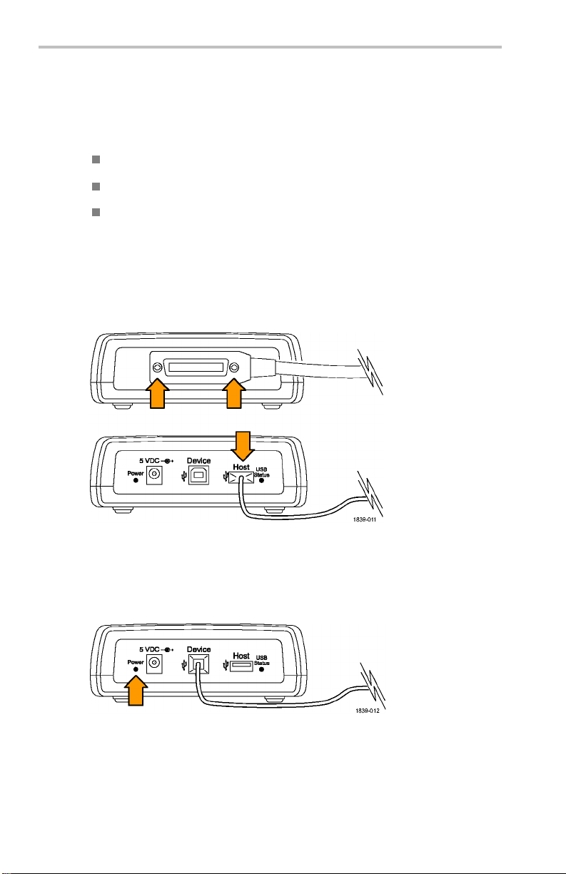
Connecting the External Power Supply
To apply power to your adapter from the optional AC power unit, do
the following procedure:
1. Connect the output power cable from the power unit to the 5 VDC
connector on the rear panel of the adapter.
2. Connect one end of the optional pow er cord to the external power
supply.
3. Connect the oth er end of the power cord to the wall po wer outlet.
4. Verify that the Power LED lights and that the USB and Adapter
Status LEDs turn on and then off. This indicates that the adapter
is initializi
TEK-USB-488 GPIB to USB Adapter User Manual 13
ng correctly.

Installation
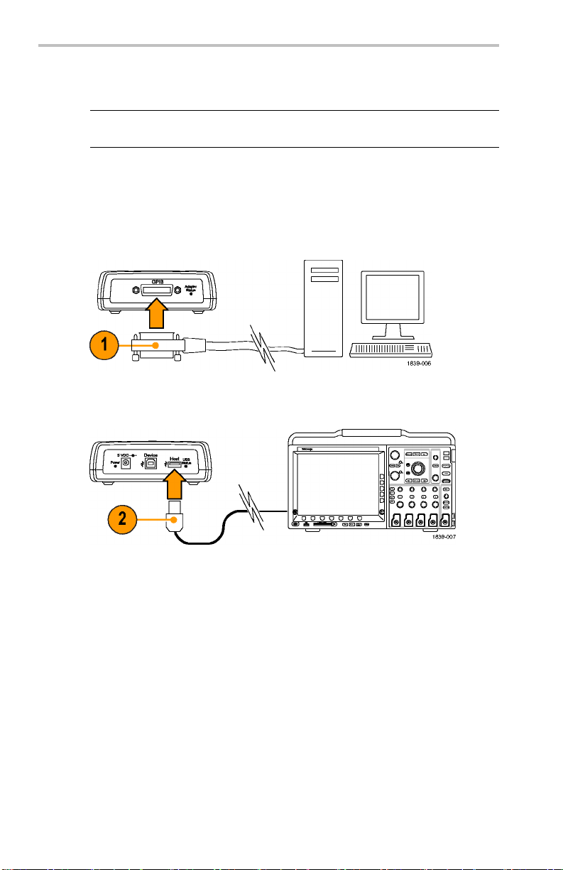
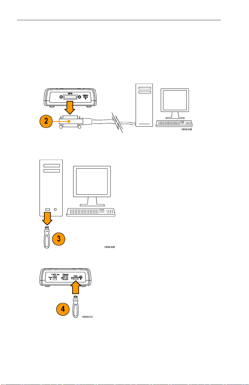
Connecting Cables
NOTE. The following cables can be connected while the instruments are
powered on.
To connect the TEK-USB-488 GPIB to USB Adapter to USB and GPIB
cables, do the f ollowing procedure:
1. Connect a GPIB cable from the GPIB controller to the GPIB po rt
on the adapter.
2. Connect a USB cable from the Device port on the instrument to the
Host port on the adapter.
14 TEK-USB-488 GPIB to USB Adapter User Manual

Setting the GPIB Address
The default GPIB address of the adapter is 1. You have to use the
default GPIB address for the adapter if you use it with instruments that
are not manufactured by Tektronix, or with older Tektronix instruments
that are not designed to support the USB protocol and USB extensions
required for setting the GPIB address of the adapter.
If you connect the Tek-USB-488 GPIB to USB Adapter to a Tektronix
USBTMC-USB488 compliant instrument desig ned to support the
adapter, such as a DPO4000 Series instrument, you can set the address
to a value from 1 through 30 using the menu system of the instrument.
To change the GPIB address from an instrument designed to support the
adapter, do the following procedure:
1. Locate the GPIB control menu on the instrument being attached.
2. Use the appropriate control to select the Talk/Listen address that
you wan t. T he instrument automatically disables and enables the
USB port so that the new address is recog nized .
3. Communicate with the instrument attached to the adapter using the
control program running on your GPIB con troller.
Installation
TEK-USB-488 GPIB to USB Adapter User Manual 15

Installation
The f ollowing parameter assumptions are made:
GPIB secondary addressing is not supported.
The default GPIB primary address i s 1. The GPIB p rimary
address can only be changed from a connected Tektronix
USBTMC-USB488 compliant instrument designed to support the
TEK-USB-488 GPIB to USB Adap ter, such as a DPO4000 Series
oscilloscope.
The GPIB Program Message Terminator (PM T ) is the GPIB end of
input (EOI) line and is not configurable. Messages that assert EO I
concurrent with a new line (hexadecimal 0a) character as the last
data byte are supported. This means th at both EOI and EOI NL
program message terminations are supported and that the NL-only
termination is not supported.
USB hubs are not supported. You can connect only one
USBTMC-USB488 compliant instrument to the USB Host port of
the adapter at any t im e.
The GPIB on/off state is online when there is an active
USBTMC-USB488 connection. You cannot change the GPIB
on/off state after the conn ection is established.
16 TEK-USB-488 GPIB to USB Adapter User Manual

Updating Firmware
To update the adapter firmware:
1. Power off the adapter.
2. Disconnect any USB or GPIB devices from the adapter.
3. Download the new firmware from www.tektronix.com to a USB
mass storage device.
Installation
4. Plug the USB mass storage device into the adapter.
5. Power on the adapter.
TEK-USB-488 GPIB to USB Adapter User Manual 17

Installation
6. Note the color of the Adapter Status LED.
7. If the LED is blinking green, power off the adapter, and reconnect
8. Power on the adapter, and verify that the Adapter Status LED is
9. If the LED is blinking red, the firmware upgrade process failed.
Solid yellow indicates that the firmware upgrade is in progress.
Wait until the LED changes color.
Blinking green indicates that the firmware was successfully
updated. Go to step 7.
Blinking red indicat es that the firmware update failed. Go to
step 9.
the USB and GPIB cables. (See page 14, Connecting Cables.)
solid green. This c om pletes the firmware update procedure.
Contact Tektronix for service.
18 TEK-USB-488 GPIB to USB Adapter User Manual

Mounting the Adapter
Although there is no rack mo unt kit available specifically for the adapter,
you can mount the adapter to a surface, such as an existing rackmount
tray or a b racket of your d esign, by doing the following procedure:
1. Remove the four adhesive-backed, plastic feet from the adapter.
2. Refer to t he dimensions shown in the illustration, and drill holes i n
the mounting surface for tw o screws.
3. Mount the ad apter using two 6-32 screws of appropriate length.
Installation
NOTE. If you are insta lling the RM4000 rackmount kit for a DPO4000
Series instrument, the kit has provisions for mounting accessories, such as
the adapter.
TEK-USB-488 GPIB to USB Adapter User Manual 19
Troubleshooting
Troubleshooting
Before starting to troubleshoo
There are no user serviceable parts.
There is no performance verification procedure.
The adapter does not support a
If your adapter does not appear to work, do the following checks:
1. Check the cables.
The USB and GPIB cable co
When you push on them gently, they should feel fully seated.
2. Check the power.
t, note the following:
USB hub.
nnectors should be fully inserted.
If the adapter is receiving power, the power indicator will be lighted.
If it is not, try gently p ushi ng in the power cable on either the power
connector
20 TEK-USB-488 GPIB to USB Adapter User Manual
or the USB Device port, whichever one you are using.

Troubleshooting
3. Check the GPIB settings.
If the adapter is receiving power, the power indicator will be lighted.
If it is not, try gently pushing in the power cable on either the power
connector or the USB Device port, whichever one you are using.
If the address setting is correct, disconnect the instrum ent from the
Host p ort on the adapter. Wait for one second , and then reconnect
the instrument to the Host port.
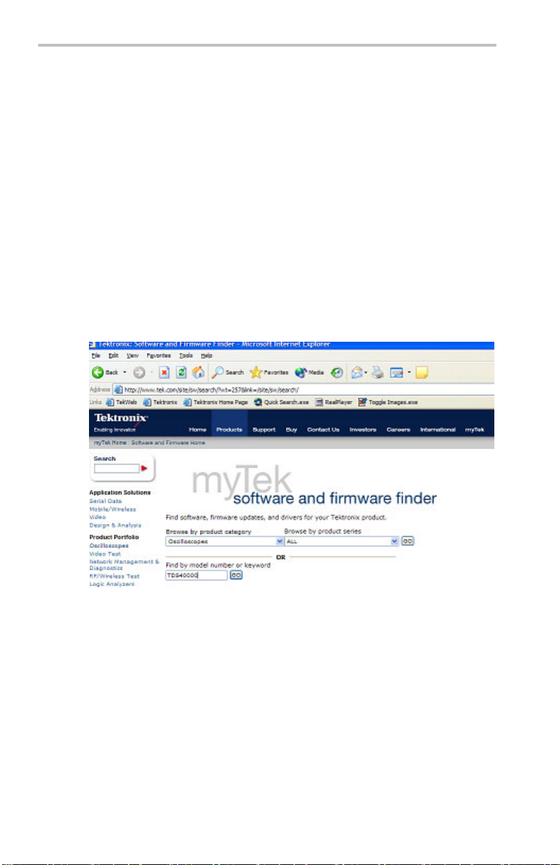
4. Check the firmware.
Use up-to-date firmware for your adapter. To do this, go to
www.tektronix.com on the Web. Load the firmwa re to the adapter
by way of the USB port. (See page 17, Upda ting Firmware.)
5. Check that your program does not lose data.
If you notice data being lost, you may have encountered the
Interrupted Query Error: Correct this situation by ensuring
that your program is written so that after the controller sends a
query to the oscilloscope, it reads all of the response data from the
oscilloscope befo re sending any other commands or queries to it.
For additional information, refer to the appropriate programmer
manual (for example, the DPO4000 Series Programmer Manual).
6. Check the indicator lights.
TEK-USB-488 GPIB to USB Adapter User Manual 21

Troubleshooting
The Ad apter Status and U SB Status indicator ligh ts on the ad apter
should be in their normal settings. To check them, refer to the
following tables:
Table 1: Adapter Status LED
Color Illumination Description
Green
Yellow
Red
None
Solid The GPIB is online and operational. A USB connection is
established.
Blinking
Solid A firmware upgrade is in process.
Blinking
Solid The adapter sensed an attempted connection of a USB
Blinking
Off If in operational mode, the GPIB is off line.
If in normal operational mode, the GPIB cannot be placed
online because there is not an active USB connection or
the connected USBTMC-USB488 device is not a Tektronix
instrument.
If in the firmware upgrade mode, the firmware upgrade has
completed successfully.
Firmware upgrade mo de: A USB mass storage device is
detected, which contains the firmware upgrade file.
Non firmwar
online du
connection to a non USBTMC-USB488 device. The adapter
refused to make the connection.
If in operational mode , the power-up self test failed.
If in the firmware upgrade mode, the firmwa re upgrade
failed.
It may also mean that the adapter is not powered on.
e to an e rror detected by the GPIB driver.
e upgrade mode: The GPIB cannot be placed
Table 2: USB Status LED
Illumination Description
Off No USB connection is present
Solid A USB connection is present, and there is no activity
Blinking
A USB connection is present, and data is being transferred
on any of the USB endpoints.
22 TEK-USB-488 GPIB to USB Adapter User Manual

Specifications
USB, General
Characteristic Description
USB Host
Version
USB Driver
Class
USB Device Characteristics
Partially to fully compliant USB 2.0 full speed host interface.
Anticipated downstream power requirements are less than 10 mA
when connected to a Tektronix oscilloscope. Sole noncompliance
point is current available when running from USB device port.
Modified USB TMC standard.
Specifications
Characteristic
USB Device
Version
Description
None. Device interface provides powe r only. A ssumes 0.5 A
availability from host device. No negotiation is performed to
acquire access to that power.
GPIB Characteristics
Characteristic Description
GPIB Version
Bulk Data Rate
Supported GPIB
Features
IEEE-488.2
Bulk data rate is highly dependent upon the characteristics of the
GPIB controller and any other peripherals coresident on the GPIB.
No provision is made to support HS (4 MB/sec) GPIB
No provision is made for DMA from GPIB
AH1, SH1, SR1, PP1, T5, L3, RL1, DC1, DT1, C0
Miscellaneous Characteristics
Characteristic Description
Current
Consumption
Current consumption is less than 0.5 ADC from 5 V
TEK-USB-488 GPIB to USB Adapter User Manual 23

Specifications
Atmospherics
Characteristic Description
Temperature:
Operating and
Nonoperating
Humidity:
Operating and
Nonoperating
Altitude:
Operating and
Nonoperating
Operating:
0°Cto+50°C(32°Fto+122°F)
Nonoperating:
–20 °C to +60 °C (–4 °F to +140 °F)
Operating:
High: 40 °C to 50 °C (104 °F to 122 °F), 10% to 60% relative
humidity
Low: 0 °C to 40 °C (32 °F to 104 °F), 10% to 90% relative humidity
Nonoperating:
High: 40 °C to 60 °C (104 °F to 140 °F), 5% to 60% relative
humidity
Low: 0 °C to 40 °C (32 °F to 104 °F), 5% to 90% relative humidity
Operating:
Up to 3,000 m (10,000 ft)
Nonoperating:
Up to 15,240 m (50,000 ft)
Physical Characteristics
Characteristic Description
Height 48.25 mm 1.90 in
Width 133.35 mm 5.25 in
Depth 133.35 mm 5.25 in
Weight 560 g 1.25 lb
24 TEK-USB-488 GPIB to USB Adapter User Manual

保証
保証
当社は本製品について、当社の認定代理店による出荷の日から 1
年間、その素材および製造工程に欠陥がないことを保証します。本
保証期間中、かかる製品に欠陥があることが判明した場合
当社の判断にて、部品および作業の費用を請求せずに当該欠陥製
品を修理するか、または当該欠陥製品と交換に代替品を提供しま
す。当社が保証遂行のために使用する部品、モジュー
替品は、新品の場合もあれば、新品同様の性能を持つ再生品の場
合もあります。交換したすべての部品、モジュール、および製品は当
社の所有物となります。
お客様が本保証に基づくサービスを受けるには、適用保証期間が
満了する前に、当該欠陥について当社に通
する適切な手配を行う必要があります。お客様には、当該欠陥製品
を梱包していただき、送料元払いにて当社指定のサービス受付セン
ターに送付していただきます。製品を
が当社サービス受付センターの所在国と同一国内にある場合には、
当社がその返送費用を負担するものとします。上記以外の場所に返
送される製品については、すべて
の他の費用を支払う責任はお客様が負うものとします。
の発送費用、関税、税、およびそ
知し、サービス実施に関
お客様に返送する際、返送先
、当社は、
ル、および代
製品の不適切な使用または整備
害、または損傷は、本保証の対象外です。当社は、次の事項につい
ては、本保証に基づくサービスを提供する義務を負わないものとしま
す。a)当社担当者以外の
の実施から生じた損傷に対する修理。b)不適切な使用または互換
性のない機器への接続から生じた損傷に対する修理。c)当社製以
外のサプライ用品の使用
修理。d)本製品が改造または他の製品と統合された場合において、
かかる改造または統合の影響により当該本製品の整備の時間または
難易度が増加した場
本保証は、明示であるか黙示であるかを問わず他のあらゆる保証の
代わりに、本製品
当社および当社代理店は、商品性または特定目的に対する適合性
についての一切の黙示保証を否認します。欠陥製品を修理または
交換するとい
様に提供される唯一かつ排他的な救済手段です。当社および当社
代理店は、間接的、限定的、偶発的、または派生的な損害について
TEK-USB-488 GPIB to USB Adapter User Manual 25
に関して当社がお客様に対して提供するものです。
う当社の責任行為は、本保証の義務違反に対してお客
により生じた損傷または機能不全に対する
合の当該本製品に対する整備。
点検の不足によって生じた欠陥、障
者による本製品の設置、修理または整備

保証
は、かかる損害の可能性を事前に通知されていたか否かにかかわら
ず、一切責任を追わないものとします。
[W2 – 15AUG04]
26 TEK-USB-488 GPIB to USB Adapter User Manual

安全にご使用いただくために
安全にご使用いただくために
人体への損傷を避け、本製品や本製品に接続されている製品
損傷を防止するために、安全性に関する次の注意事項をよくお読み
ください。
安全にご使用いただくために、本製品の指示に従ってください。
資格のあるサービス担当者以外は、保守点検手順を実
ださい。
行しないでく
への
火災や人体への損傷を避けるには
適切な電源コードを使用してください: 本製品用に指定され、使用さ
れる国で認定された電源コードのみを使用してください。
い:
すべての端子の定格に従ってくださ
ために、本製品のすべての定格とマーキングに従ってください。本製
品に電源を接続する前に、定格の詳細について、製品マニュアルを
参照してください。
カバーを外した状態では使用しないでください: カバーやパネルを外
した状態で本製品を動作させないでください。
故障の疑いがあるときは使用しないでください: 本製品に故障の疑い
がある場合、資格を有するサー ビス担当者に検査を依頼してくださ
い。
火災や感電の危険を避ける
回路の露出を避けてください: 電源がオンのときに、露出した接続部
分やコンポーネントに触れないでください。
適切な AC アダプタを使用してください: 本製品専用の AC アダプタ
のみをご使用ください。
防護ゴーグルを着用してください: 強力な光線またはレーザー照射に
さらされる危険性がある場合は、防護ゴーグルを着用してください。
TEK-USB-488 GPIB to USB Adapter User Manual 27

安全にご使用いただくために
湿気の多いところでは使用しないでください:
爆発しやすい環境では動作させないでください:
製品の表面を清潔で乾燥した状態に保ってください:
充分な換気を確保してください:
ユーザ・マニュアル
の設置手順を参
照し、充分な換気を確保してください。
本マニュアル内の用語
このマニュアルでは次の用語を使用します。
警告: 人体や生命に危害をおよぼすおそれのある状態や行為を示しま
す。
注意: 本製品やその他の接続機器に損害を与える状態や行為を示し
ます。
本製品に関する記号と用語
本製品では、次の用語を使用します。
DANGER: ただちに人体や生命に危険をおよぼす可能性がある
ことを示し ます。
WARNING: 人体や生命に危険をおよぼす可能性があることを
示します。
CAUTION: 本製品を含む周辺機器に損傷を与える可能性があ
ることを示します。
本製品では、次の記号を使用します。
28 TEK-USB-488 GPIB to USB Adapter User Manual

適合性に関する情報
このセクションでは、本機器が適合している EMC 基準および環境基
準について説明します。
EMC
EC 適合宣言 - EMC
指令 2004/108/EC 電磁環境両立性に適合します。『Official Journal
of the European Communities』に記載の以下の仕様に準拠します。
適合性に関する情報
EN 61326-1 2006: 測定、制御、および実験用途の電子機器を対象
とする EMC 基準。
123
CISPR 11:2003:グループ 1、クラス A、放射および伝導エミッショ
ン
IEC 61000-4-2:2001:静電気放電イミュニティ
IEC 61000-4-3:2002:RF 電磁界イミュニティ
IEC 61000-4-4:2004:ファスト・トランジェント/バースト・イミュニ
ティ
IEC 61000-4-5:2001:電源サージ・イミュニティ
IEC 61000-4-6:2003:伝導 RF イミュニティ
IEC 61000-4-11:2004:電圧低下と停電イミュニティ
EN 61000-3-2:2006: AC 電源高調波エミッション
EN 61000-3-3:1995: 電圧の変化、変動、およびフリッカ
1
本製品は住居区域以外での使用を目的としたものです。住居区域で使用
すると、電磁干渉の原因となることがあります。
2
本製品をテスト対象に接続した状態では、この規格が要求するレベルを超
えるエミッションが発生する可能性があります。
3
ここに挙げた各種 EMC 規格に確実に準拠するには、高品質なシールドを
持つインタフェース・ケーブルが必要です。
欧州域内連絡先:
TEK-USB-488 GPIB to USB Adapter User Manual 29

適合性に関する情報
Tektronix UK, Ltd.
Western Peninsula
Western Road
Bracknell, RG12 1RF
United Kingdom
オーストラリア/ニュージーランド適合宣言 - EMC
ACMA に従い、次の規格に準拠することで Radiocommunications Act
の EMC 条項に適合しています。
CISPR 11:2003:グループ 1、クラス A、放射および伝導エミッショ
ン(EN 61326-1:2006 に準拠)
安全性
機器の種類
測定機器
汚染度
製品内部およびその周辺で発生する可能性がある汚染の尺度です。
通常、製品の内部環境は外部環境と同じとみなされます。製品は、
その製品に指定されている環境でのみ使用してください。
汚染度 1:汚染なし、または乾燥した非導電性の汚染のみが発
生します。このカテゴリの製品は、通常、被包性、密封性のある
ものか、クリーン・ルームでの使用を想定したものです。
汚染度 2:通常、乾燥した非導電性の汚染のみが発生します。た
だし、結露によって一時的な導電性が発生することもまれにあり
ます。これは、標準的なオフィスや家庭内の環境に相当します。
一時的な結露は製品非動作時のみ発生します。
30 TEK-USB-488 GPIB to USB Adapter User Manual

適合性に関する情報
汚染度 3:導電性のある汚染、または通常は乾燥して導電性を持
たないが結露時に導電性を帯びる汚染。これは、温度、湿度の
いずれも管理されていない屋内環境に相当します。日光や雨、
風に対する直接の曝露からは保護されている領域です。
汚染度 4:導電性のある塵、雨、または雪により持続的な導電性
が生じる汚染。これは一般的な屋外環境に相当します。
汚染度
汚染度 2(IEC 61010-1 の定義による)。注:屋内使用のみについて
の評価です。
TEK-USB-488 GPIB to USB Adapter User Manual 31

適合性に関する情報
環境条件について
このセクションでは本製品が環境に及ぼす影響について説明します。
使用済み製品の処理方法
機器またはコンポーネントをリサイクルする際には、次のガイドライン
を順守してください。
機器のリサイクル: 本製品の製造には天然資源が使
す。この製品には、環境または人体に有害となる可能性のある物質
が含まれているため、製品を廃棄する際には適切に処理する必要が
あります。有害物質の放出を防ぎ、天然資源
機材の大部分を再利用またはリサイクルできる適切な方法で処理し
てください。
この記号は、本製品が WEEE(廃棄電気・電子機器)
および バッテリに 関 す る Directive 2002/96/EC および
2006/66/EC に基づき、EU の諸要件に準拠し ているこ
とを示しています。リサイクル方法については、Tektronix
Web サ イト(www.tektronix.com)の 「Service/Support」の
セクションを参照してください。
の使用を減らすため、
用されていま
有害物質に関する規制
本製品は Monitoring and Control(監視および制御)装置に分類され
ており、2002/95/EC RoHS Directive(電気・電子機器含有特定危険
物質使用制限指令)の適用範囲外です。
32 TEK-USB-488 GPIB to USB Adapter User Manual

まえがき
このマニュアルでは、TEK-USB-488 型 GPIB-USB アダプタの設置
方法と使用方法について説明します。このアダプタを使用すると、
USBTMC-USB488 対応機器(DPO4000 シリーズ・オシロスコープな
ど)の USB デバイス・ポートを GPIB(IEEE488)コントローラに接続す
ることができます。
コントローラ GPIB アダプタ USB 機器
主な特長
主な特長は次のとおりです。
まえがき
USBTMC-USB488 対応の当社機器を USB ポート経由で GPIB
制御。USBTMC プロトコルにより、IEEE488 準拠のメッセージを使
用した通信が可能です。これにより、USB ハードウェア上で GPIB
ソフトウェア・アプリケーションを使用できます。
データを高速転送します。
USB ホストまたはオプションの外部電源から電源を供給できます。
TEK-USB-488 GPIB to USB Adapter User Manual 33

設置
設置
アダプタを開梱し、スタンダード・アクセサリとして記載されているす
べての付属品が含まれていることを確認してください。最新情報につ
いては、当社 Web サイト(www.tektronix.com)をご覧ください。
スタンダード・アクセサリ
説明 部品番号
ユーザ・マニュアル
USB ケーブル(2 本、各 1m )
オプショナル・アクセサリ
説明 部品番号
GPIB ケーブル(1 m)
GPIB ケーブル(2 m)
外部電源(下記の電源コードは別
売り)
電源コード(米国仕様)
電源コード(欧州共通仕様)
電源コード(英国仕様)
電源コード(オーストラリア仕
様)
電源コード(スイス仕様)
電源コード(日本仕様)
電源コード(中国仕様)
電源コード(インド/南アフリ
カ仕様)
07
1-1839-XX
17
4-4401-XX
2-0991-XX
01
01
2-0991-XX
1
19-8724-XX
16
1-0066-XX
16
1-0066-XX
16
1-0066-XX
16
1-0066-XX
16
1-0154-XX
1-0342-XX
16
16
1-0304-XX
1-0400-XX
16
34 TEK-USB-488 GPIB to USB Adapter User Manual

コントロールおよびコネクタ
1. GPIB コネクタ
2. アダプタ・ステータス LED(47 ページの 表 3 参照)。
設置
3. USB ステータス LED(48 ページの 表 4 参照)。
4. USB ホスト・ポート。被制御機器の USB デバイス・ポートとの接続
に使用します。
5. USB デバイス・ポート。このポートを介して USB ホストからアダプ
· に電源を供給します。電源供給専用であり、USD デバイス
機能は備わっていません。
6. 電源 コネクタ。オプションの外部 電源(当 社部品番
号119-8724-XX)を接続します。
7. 電源 LED電源が供給されていると点灯します。
TEK-USB-488 GPIB to USB Adapter User Manual 35

設置
電源の接続
アダプタへの電源供給方法には、次の 2 通りの方法があります。
USB 2.0 ホスト・ポートから供給
オプションの外部電源から供給
USB 接続による電源供給
USB ホスト・ポートからアダプタへ電源を供給するには、次の手順に
従います。
1. USB ケーブルのデバイス側の端を、アダプタ・リア・パネルの USB
デバイス・ポートに接続します。
2. USB ケーブルのホスト側の端を、電源供給元とする機器(被制御
機器または PC など)の USB ホスト・ポートに接続します。
3. 電源 LED が点灯していること、および、USB ステータス LED と
アダプタ・ステータス LED が点灯して消えることを確認します。こ
の状態は、アダプタの初期化が正常に行われていることを示し
ます。
36 TEK-USB-488 GPIB to USB Adapter User Manual

設置
外部電源の接続による電源供給
オプションの AC 電源ユニットからアダプタへ電源を供給するには、
次の手順に従います。
1. 電源ユニットの出力電源ケーブルをアダプタ・リア・パネルの 5
VDC コネクタに接続します。
2. オプションの電源コードの一方の端を外部電源ユニットに接続し
ます。
3. 電源コードのもう一方の端をコンセントに差し込みます。
4. 電源 LED が点灯していること、および、USB ステータス LED と
アダプタ・ステータス LED
の状態は、アダプタの初期化が正常に行われていることを示し
ます。
TEK-USB-488 GPIB to USB Adapter User Manual 37
が点灯して消えることを確認します。こ
設置
ケーブルの接続
注: このセクションで説明するケーブルは、機器の電源をオンにした状
態で接続できます。
TEK-USB-488 型 GPIB-USB アダプタに USB ケーブルと GPIB ケー
ブルを接続するには、次の手順に従います。
1. GPIB コントローラとアダプタの GPIB ポートを GPIB ケーブルで
接続します。
2. 機器のデバイス・ポートとアダプタのホスト・ポートを USB ケーブ
ルで接続します。
38 TEK-USB-488 GPIB to USB Adapter User Manual

GPIB アドレスの設定
アダプタのデフォルトの GPIB アドレスは 1 です。アダプタを他社製
品に使用する場合、または、USB プロトコルと USB 拡張に未対応の
古い当社製品でアダプタの GPIB アドレスを設定できない場合は、こ
のデフォルトの GPIB アドレスを使用してください。
Tek-USB-488 型 GPIB-USB アダプタを Tektronix USBTMC-USB488
対応機器(DPO4000 シリーズなど)に接続すると、機器のメニューを
使用してアドレスを 1 ~ 30 の範囲で設定することができます。
アダプタに対応している機器から GPIB アドレスを変更するには、次
の手順に従います。
1. 接続先の機器で GPIB コントロール・メニューを開きます。
2. 適切なコントロールを使用して任意の Talk/Listen アドレスを選
択します。USB ポートがいったん無効化された後、有効化され、
新しいアドレスが自動的に認識されます。
3. GPIB コントローラ上の制御プログラムを使用して、アダプタに接
続されている機器との通信を行います。
設置
TEK-USB-488 GPIB to USB Adapter User Manual 39

設置
想定されるパラメータ設定は以下のとおりです。
GPIB セカンダリ・アドレスはサポートされません。
デフォルトの GPIB プライマリ・アドレスは 1 です。この GPIB プライ
マリ・アドレスは、接続している機器が Tektronix USBTMC-USB488
に準拠し TEK-USB-488 型 GPIB-USB アダプタをサポートして
いる場合のみ(DPO4000 シリーズ・オシロスコープなど)、その機
器から変更することができます。
GPIB プログラム・メッセージ・ターミネータ(PMT)は、GPIB の EOI
ラインであり、設定することはできません。EOI と最終データ・バ
イトの改行文字(16 進の 0a)を同時にアサートするメッセージが
サポートされています。つまり、EOI および EOI NL によるプログ
ラム・メッセージ・ターミネーションはどちらもサポートされていま
すが、NL 単独のターミネーションはサポートされていません。
USB ハブはサポートされていません。アダプタの USB ホスト・ポー
トに接続できるのは、常に、USBTMC-USB488 対応の機器 1 台
のみです。
GPIB の on/off 状態は、アクティブな USBTMC-USB488 接続が
存在する場合にオンラインになります。接続が確立された後で
GPIB の on/off を変更することはできません。
40 TEK-USB-488 GPIB to USB Adapter User Manual

ファームウェアの更新
アダプタのファームウェアを更新するには、次の手順に従います。
1. アダプタの電源をオフにします。
2. アダプタに接続されている USB デバイスまたは GPIB デバイス
があれば、それらを切り離します。
3. 新しいファームウェアを www.tektronix.com から大容量 USB スト
レージ・デバイスにダウンロードします。
設置
4. USB ストレージ・デバイスをアダプタに差し込みます。
5. アダプタの電源をオンにします。
TEK-USB-488 GPIB to USB Adapter User Manual 41

設置
6. アダプタ・ステータス LED の色に注目します。
黄色に点灯: ファームウェアの更新が進行中であることを示
します。LED の色が変わるまで待ちます。
緑色に点滅: ファームウェアの更新が成功したことを示しま
す。ステップ 7 に進みます。
赤色に点滅: ファームウェアの更新が失敗したことを示しま
す。ステップ 9 に進みます。
7. LED が緑色に点滅している場合は、アダプタの電源をオフにし、
USB ケーブルと GPIB ケーブルを接続し直します。 (38 ページ
「ケーブルの接続」 参照)。
8. アダプタの電源をオンにし、アダプタ・ステータス LED が緑色に
点灯することを確認します。これで、ファームウェアの更新手順
は終了です。
9. LED が赤色に点滅している場合は、ファームウェアの更新が失
敗しています。当社サービス担当までお問い合わせください。
42 TEK-USB-488 GPIB to USB Adapter User Manual

アダプタの設置
アダプタ専用のラックマウント・キットはありませんが、以下の手順によ
り、既存のラックマウント・トレーや独自設計のブラケットにアダプタを
設置することができます。
1. アダプタからプラスティック製の足(4 個)を剥がして取り外します。
2. 下図の寸法に合わせて、設置面にネジ穴を 2 つ開けます。
3. 適当な長さの 6-32 ネジを 2 個使用して、アダプタを固定します。
設置
注: DPO4000 シリーズ用の RM4000 型ラックマウント・キットを使用する
と、アダプタなどのアクセサリを設置するのが容易です。
TEK-USB-488 GPIB to USB Adapter User Manual 43

トラブルシューティング
トラブルシューティング
トラブルシューティングを開始する前に、以下の点にご注意ください。
お客様が修理できる部品はありません。
パフォーマンス検証用の手順はありません。
アダプタは USB ハブをサポートしていません。
44 TEK-USB-488 GPIB to USB Adapter User Manual

トラブルシューティング
アダプタが正しく動作しないと思われる場合は、次の項目をチェック
してください。
1. ケーブルをチェックします。
USB および GPIB ケーブル・コネクタは、奥まで完全に差し込む
必要があります。ケーブルをゆっくりと押し込むと、所定の位置で
正しくかみ合います。
2. 電源をチェックします。
アダプタに電源が供給されている場合、電源 LED が点灯しま
す。点灯しない場合は、使用している電源コネクタ側または USB
デバイス・ポート側で、電源ケーブルをゆっくり押し込んでみてく
ださい。
TEK-USB-488 GPIB to USB Adapter User Manual 45
トラブルシューティング
3. GPIB 設定をチェックします。
アダプタに電源が供給されている場合、電源 LED が点灯しま
す。点灯しない場合は、使用している電源コネクタ側または USB
デバイス・ポート側で、電源ケーブルをゆっくり押し込んでみてく
ださい。
アドレス設定が正しければ、アダプタのホスト・ポートから機器を
取り外します。1 秒間待ってから機器をホスト・ポートに接続し直
します。
4. ファームウェアをチェックします。
アダプタのファームウェアは最新版である必要があります。最新
版は当社 Web サイト(www.tektronix.com)で入手できます。入手
したファームウェアは USB ポートを介してアダプタに読み込んで
ください。 (41 ページ 「ファームウェアの更新」 参照)。
5. プログラムでデータが喪失してないかをチェックします。
データの喪失がある場合は Interrupted Query Error: というエ
ラー・メッセージが表示される可能性があります。この状況を修正
するには、プ
に対してクエリを送信した後、オシロスコープからのすべての応
答データを読み込んでから次のコマンドまたはクエリを送信して
いるかを確
46 TEK-USB-488 GPIB to USB Adapter User Manual
ログラムをチェックし、コントローラがオシロスコープ
認する必要があります。

詳細については、関連のプログラマ・マニュアル(『DPO4000 シ
リーズ・プログラマ・マニュアル』など)を参照してください。
6. LED の状態をチェックします。
アダプタ上のアダプタ・ステータス LED および USB ステータス
LED は、正しい設定になっている必要があります。以下の表を参
照して設定をチェックしてください。
表 3: Adapter Status (アダプタ・ステータス) LED
色発光状態説明
トラブルシューティング
緑色
黄色
赤
なし
点灯 GPIB がオンラインで機能しています。USB 接続が確
立されています。
点滅
点灯 ファームウェアのアップグレードが進行中です。
点滅
点灯
点滅
オフ(消灯)動作モード: GIPB がオフラインです。
通常の動作モード: GPIB がオンラインに移行できま
せん。原因としては、アクティブな USB 接続がない
か、接続されている USBTMC-USB488 デバイスが当
社製品ではないことが考えられます。
ファームウェア更新モード: ファームウェアの更新が
成功しています。
ファームウェア・アップグレード・モード: ファームウェ
ア・アップグレード・ファイルが格納された大容量 USB
ストレージ・デバイスが検出されました。
ファームウェア・アップグレード・モード以外: GPIB が
オンラインに移行できません。GPIB ドライバでエラー
が検出されています。
非 USBTMC-USB488 デバイスへの USB 接続が試み
られましたが、アダプタによって拒絶されました。
動作モード
ファーム
アの更新
アダプタの電源がオフになっている場合もあります。
: 電源オン時の自己診断が失敗しました。
ウェア・アップグレード・モード: ファームウェ
が失敗しました。
TEK-USB-488 GPIB to USB Adapter User Manual 47

トラブルシューティング
表 4: USB Status (USB ステータス) LED
発光状態 説明
オフ(消灯) USB 接続がありません。
点灯
点滅
USB 接続がありますが、非アクティブ状態です。
USB 接続が確立され、USB エンドポイントにデータが
転送されています。
48 TEK-USB-488 GPIB to USB Adapter User Manual

仕様
USB、一般
特性 説明
仕様
USB ホスト・バー
ジョン
USB ドラ イ バ ・ ク
ラス
高速の USB 2.0 ホスト・インタフェースをほぼ完全サポート。
当社製オシロスコープに接続の場合、期待されるダウンスト
リームの電源要件は 10 mA 未満。USB デバイス・ポートか
ら電源を供給する場合に得られる電流のみ、基準を満たし
ていない。
USB TMC 規格(改訂)
USB デバイスの特性
特性
USB デ バイ ス・
バージョン
説明
なし。デバイス・インタフェースは電源のみを供給。ホスト・デ
バイスから得られる電流は 0.5 A を想定。この電源へのアク
セスを獲得するためのネゴシエーションは行われない。
GPIB の特性
特性 説明
GPIB バージョン
バルク・データ・
レート
サポートされてい
るGPIB機能
IEEE-488.2
バルク・データ・レートは、GPIB コントローラおよび GPIB に
混在する他の周辺機器の特性によって大きく異なる。
HS(4 MB/s)GPIB のサポートについては規定なし。
GPIB からの DMA については規定なし。
AH1、SH1、SR1、PP1、T5、L3、RL1、DC1、DT1、C0
その他の特性
特性 説明
消費電流 消費電流は 0.5 ADC 未満(5 V)
TEK-USB-488 GPIB to USB Adapter User Manual 49

仕様
周辺環境
特性 説明
温度: 動作時お
よび非動作時
湿度:動作時お
よび非動作時
高度: 動作時お
よび非動作時
動作時:
0 ゚C ~ +50 ゚C(32 ゚F ~ +122 ゚F)
非動作時:
-20 ℃~ +60 ℃(-4 ゚F ~ +140 ゚F)
動作時:
最高: 40 ℃~ 50 ℃(104 ゚F ~ 122 ゚F)、相対湿度 10% ~
60%
最低:0℃~40℃(32゚F~104゚F)、相対湿度10%~90%
非動作時:
最高: 40 ℃~ 60 ℃(104 ゚F ~ 140 ゚F)、相対湿度 5% ~
60%
最低: 0 ℃~ 40 ℃(32 ゚F ~ 104 ゚F)、相対湿度 5% ~ 90%
動作時:
0 ~ 3,000 m
非動作時:
0 ~ 15,240 m
物理特性
特性 説明
高さ
幅
奥行き
質量
48.25 mm
133.35 mm
133.35 mm
560 g
1.90 インチ
5.25 インチ
5.25 インチ
1.25 ポンド
50 TEK-USB-488 GPIB to USB Adapter User Manual

保修
保修
Tektronix 保证,本产品自发货之日起一 (1) 年内不会出现材料和
工艺缺陷。如果在保修期内证明任何此类产品有缺陷,Tektronix
将会选择对缺陷产品进行维修或更换,不收部件和人工费用
Tektronix 作保修用途的部件、模块和更换产品可能是全新的,
或者经修理具有相当于新产品的性能。所有更换的部件、模块和
产品将成为 Tektronix 的财产。
为得到本保证声明承诺的服务,客户必须在保修期内向 Tektronix
通报缺陷,并为服务的履行做适当安排。客户应
品并托运到 Tektronix 指定的维修中心,同时预付运费。如果产
品要运送到 Tektronix 维修中心所在国范围内的地点,Tektronix
应支付向客户送返产品的费用。如果产品送
客户应负责支付所有的运费、关税、税金及任何其他费用。
负责包装缺陷产
返到任何其他地点,
。
本保证声明不适用于由于使用不当或者
成的任何缺陷、故障或损坏。Tektronix 根据本保证的规定无义
务提供以下服务:a) 修理由非 Tektronix 服务代表人员对产品
进行安装、修理或维护所导致的损坏
与不兼容的设备连接造成的损坏;c) 修理由于使用非 Tektronix
提供的电源而造成的任何损坏或故障;d) 维修已改动或者与其
他产品集成的产品(如果这种改
或难度)。
本保证由 TEKTRONI
示或暗示的保证。TEKTRONIX 及其供应商拒绝对用于特殊目的的
适销性或适用性做任何暗示的保证。TEKTRONIX 对于违反本保修
所提供的独有和唯一的补
品。无论 TEKTRONIX 及其供应商是否被预先告知可能发生任何间
接、特殊、偶然或必然的损坏,TEKTRONIX 及其供应商对这些损
坏均概不负责。
[W2 – 15AUG04]
X 针对本产品而订立,用于替代任何其他的明
救措施是负责为客户修理或更换缺陷产
动或集成会增加产品维修的时间
维护保养不当或不足所造
;b) 修理由于使用不当或
TEK-USB-488 GPIB to USB Adapter User Manual 51

常规安全概要
常规安全概要
详细阅读下列安全性预防措施,以避免人身伤害,并防止损坏本
产品或与本产品连接的任何产品。
为避免可能的危险,请务必按照规定使用本产品。
只有合格人员才能执行维修程序。
避免火灾或人身伤害
使用合适的电源线: 请只使用本产品专用并经所在国家/地区认
证的电源线。
遵循所有终端额定值: 为避免火灾或电击,请遵守产品上的所有
额定值和标记。在对产品进行连接之前,请首先查阅产品手册,
了解有关额定值的详细信息。
切勿开盖操作: 请勿在外盖或面板打开时运行本产品。
产品带有可疑故障时不要操作: 如果怀疑本产品已损坏,请让合
格的维修人员进行检查。
远离裸露电路: 电源接通后,请勿接触裸露的线路和元件。
使用合适的交流适配器: 只能使用为本产品指定的专用交流适配
器。
佩戴眼睛保护装置: 如果暴露在高强度光线中或存在激光辐射,
请佩戴眼睛保护装置。
请勿在潮湿环境下操作:
请勿在易燃易爆的气体中操作:
请保持产品表面清洁干燥:
保持适当的通风:
息,请参阅手册中的安装说明。
52 TEK-USB-488 GPIB to USB Adapter User Manual
有关如何安装产品使其保持适当通风的详细信
常规安全概要
本手册中的术语
本手册中可能出现以下术语:
警告: “警告”声明指出可能会造成人身伤害或危及生命安全的情
况或操作。
注意: “注意”声明指出可能对本产品或其他财产造成损坏的情况
或操作。
产品上的符号和术语
产品上可能出现以下术语:
DANGER “危险”表示您看到该标记时可直接接触到人身伤害
的危险。
WARNING “警告”表示您看到该标记时不会直接接触到人身
伤害的危险。
CAUTION “注意”表示可能会对本产品或其他财产带来的危
险。
产品上可能出现以下符号:
TEK-USB-488 GPIB to USB Adapter User Manual 53

符合性信息
符合性信息
此部分列出仪器符合的 EMC(电磁兼容性)和环境标准。
EMC 符合性
EC 一致性声明 - EMC
符合 Directive 2004/108/EC 有关电磁兼容性的要求。已证明符
合《欧洲共同体公报》中所列的以下技术规格:
EN 61326-1 2006: 测量、控制和实验室用电气设备 EMC 要求。
123
CISPR 11:2003。放射和传导发射量,组 1,A 类
IEC 61000-4-2:2001。静电放电抗扰性
IEC 61000-4-3:2002。射频电磁场抗扰性
IEC 61000-4-4:2004。电气快速瞬变/突发抗扰性
IEC 61000-4-5:2001。电源线路浪涌抗扰性
IEC 61000-4-6:2003。传导射频抗扰性
IEC 61000-4-11:2004。电压跌落和中断抗扰性
EN 61000-3-2:2006: 交流电源线谐波辐射
EN 61000-3-3:1995: 电压变化、偏移和闪烁
1
本产品仅为在非居民区内使用。在居民区内使用可能造成电磁干扰。
2
当该设备与测试对象连接时,可能产生超过此标准要求的辐射级别。
3
为确保符合上面列出的 EMC 标准,应使用高质量的屏蔽接口电缆。
欧洲联系方式:
Tektronix UK, Ltd.
Western Peninsula
Western Road
Bracknell, RG12 1RF
United Kingdom(英国)
54 TEK-USB-488 GPIB to USB Adapter User Manual

澳大利亚/新西兰一致性声明 - EMC
根据 ACMA,符合 Radiocommunications Act(无线电通信法)有
关 EMC 规定的以下标准:
CISPR 11:2003。 放射 和传 导 发射 量 ,组 1, A 类 ,依 照
EN 61326-1:2006。
安全符合性
设备类型
测试和测量设备。
污染度说明
测量产品周围和产品内部的环境中可能出现的污染。通常认为
产品的内部环境与外部环境相同。产品只应该在其规定环境中使
用。
污染度 1。无污染或仅出现干燥、非传导性污染。对这种类
型的产品,通常进行封装、密封或将其置于干净的房间中。
符合性信息
污染度 2。通常只发生干燥、非传导性污染。偶尔会发生由
凝结引起的临时传导。典型的办公室/家庭环境属于这种情
况。只有当产品不能使用时,才会发生临时凝结。
污染度 3。传导性污染,或由于凝结会变成传导性污染的干
燥、非传导性污染。这些场所建有遮盖设施,温度或湿度不
受控制。此类区域不会受阳光、雨水或自然风的直接侵害。
污染度 4。通过传导性的尘埃、雨水或雪产生永久的可导性
污染。户外场所通常属于这种情况。
污染度
污染度 2(在 IEC 61010-1 中定义)。注意:仅适合在室内使
用。
TEK-USB-488 GPIB to USB Adapter User Manual 55

符合性信息
环境注意事项
本部分提供有关产品对环境影响的信息。
产品报废处理
回收仪器或元件时,请遵守下面的规程:
设备回收: 生产本设备需要提取和使用自然资源。如果对本产品
的报废处理不当,则该设备中包含的某些物质可能会
体健康有害。为避免将有害物质释放到环境中,并减少对自然资
源的使用,建议采用适当的方法回收本产品,以确保大部分材料
可以正确地重复使用或回收。
有害物质限制
根据分类,本产品属于监视控制设备,不属于 2002/95/EC RoHS
Directive 规定的范畴。
对环境或人
此符号表示该产品按照 Directives 2002/96/EC
和 2006/66/EC, 符合欧盟对废旧电子和电气设备
(WEEE) 以及电池的要求。有关选件回收的信息,请
查 看 Tektronix 网站 (www.tektronix.com) 上的
Support/Service(支持/服务)部分。
56 TEK-USB-488 GPIB to USB Adapter User Manual

前言
本手册介绍了 TEK-USB-488 GPIB-USB 适配器的安装和操作。使
用该适配器,可以将兼容 USBTMC-USB488 的仪器上的 USB 设备
端口(例如 DPO4000 系列示波器)与 GPIB (IE
连接。
控制 器 GPIB 适配器 USB 仪器
主要功能
主要功能包括:
通过 USB 端口对兼容 USBTMC-USB488 的 Tektronix 仪器进
行 GPIB 控制。USBTMC 协议使 USB 设备可以使用 IEEE488
形式的消息进行通信。因此,
软件应用程序。
可以在 USB 硬件上运行 GPIB
前言
EE488) 控制器相
快速数据传输速率
由 USB 主机或可选外部电源供电
TEK-USB-488 GPIB to USB Adapter User Manual 57

安装
安装
打开适配器包装,确认您收到了所有被列为标准附件的物品。请
访问 Tektronix 网站 (www.tektronix.com) 了解最新信息。
标准附件
说明 部件号
用户手册
USB 电缆(各 2 根,1 米)
可选附件
说明 部件号
GPIB 电缆(1 米)
GPIB 电缆(2 米)
外部电源(电源线需另行订购)
适用于美国地区的电源线
适用于欧洲地区的电源线
适用于英国地区的电源线
适用于澳大利亚地区的电源
线
适用于瑞士地区的电源线
适用于日本地区的电源线
适用于中国地区的电源线
适用于印度/南非地区的电
源线
1-1839-XX
07
17
4-4401-XX
2-0991-XX
01
01
2-0991-XX
19-8724-XX
1
1-0066-XX
16
1-0066-XX
16
1-0066-XX
16
1-0066-XX
16
1-0154-XX
16
16
1-0342-XX
1-0304-XX
16
1-0400-XX
16
58 TEK-USB-488 GPIB to USB Adapter User Manual

控件和连接器
1. GPIB 连接器
2. Adapter Status(适配器状态)指示器 ( 见表5第69页)
安装
3. USB Status(USB 状态)指示器 ( 见表6第69页)
4. USB Host(USB 主机)端口,用于和被控仪器上的 Device
(USB 设备)端口相连。
5. USB 设备端口。USB 主机可通过此端口为适配器供电。该端
口仅用于供电。不提供任何 USB 设备功能。
6. 5 VDC 电源连接器。适用于可选外部电源,Tektronix 部
件号 119-8724-XX。
7. Power(电源)指示器。接通电源时变亮。
连接电源
可以采用以下两种方法之一为适配器供电:
从 USB 主机端口
从可选外部电源
TEK-USB-488 GPIB to USB Adapter User Manual 59

安装
连接 USB 电源
若要从 USB 主机端口为适配器供电,请执行以下步骤:
1. 将 USB 电缆的设备端与适配器后面板上的 USB Device(USB
设备)端口相连。
2. 将 USB 电缆的主机端与供电装置(通常情况下为被控仪器或
PC)上的 USB Host(USB 主机)端口相连。
3. 确认 Power(电源)LED 变亮,并且 USB Status(USB 状
态)和 Adapter Status(适配器状态)LED 先变亮,然后又
熄灭。这表示适配器初始化正常。
60 TEK-USB-488 GPIB to USB Adapter User Manual

安装
连接外部电源
若要从可选交流电源设备为适配器供电,请执行以下步骤:
1. 将电源设备的输出电源线与适配器后面板上的 5 VDC 连接器
相连。
2. 将可选电源线的一端连接至外部电源。
3. 将电源线的另一端连接至墙上电源插座。
4. 确认 Power(电源)LED 变亮,并且 USB Status(USB 状
态)和 Adapter Status(适配器状态)LED 先变亮,然后又
熄灭。这表示适配器初始化正
常。
TEK-USB-488 GPIB to USB Adapter User Manual 61

安装
连接电缆
说明: 在仪器通电期间可以连接以下电缆。
要将 TEK-USB-488 GPIB-USB 适配器与 USB 和 GPIB 电缆连接,
请执行以下步骤:
1. 将与 GPIB 控制器相连的 GPIB 电缆连接至适配器上的 GPIB
2. 将与仪器 Device(设备)端口相连的 USB 电缆连接至适配
端口。
器上的 Host(主机)端口。
62 TEK-USB-488 GPIB to USB Adapter User Manual

设置 GPIB 地址
适配器的默认 GPIB 地址为 1。如果将其用于非 Tektronix 制
造的仪器或者 Tektronix 较早不支持 USB 协议和 USB 扩展(设
置适配器 GPIB 地址时需要)的仪器,则必须为适配器使用默认
GPIB 地 址。
如果将 Tek-USB-488 GPIB-USB 适配器连接至设计用于支持适配
器且兼容 Tektronix USBTMC-USB488 的仪器(如 DPO4000 系列
仪器),则可以使用仪器的菜单系统将地址设置为 1 至 30 之
间的值。
若要通过设计用于支持适配器的仪器更改 GPIB 地址,请执行以
下步骤:
1. 在相连的仪器上查找 GPIB 控制菜单。
2. 使用合适的控制选择所需的“发/收”地址。仪器将自动禁用
和启用 USB 端口,以识别新的地址。
3. 使用 GPIB 控制器上运行的控制程序与适配器上连接的仪器
进行通信。
使用的参数假设如下:
不支持 GPIB 二级地址。
安装
默认的 GPIB 主地址为 1。GPIB 主地址的更改只能通过连
接到兼容 Tektronix USBTMC-USB488,而且它设计用于支持
TEK-USB-488 GPIB-USB 适配器的仪器(例如 DPO4000 系列示
波器)。
GPIB 程序消息终止符 (PMT) 是 GPIB 输入 (EOI) 行的结尾,
无法进行配置。支持将 EOI 与一个新行(十六进制 0a)字
符并存的情况作为最后数据字节的消息。这就意味着 EOI 和
EOI NL 程序消息终止都受支持,仅 NL 终止不受支持。
不支持 USB 集线器。所以在任何时候,仅能将一台兼容
USBTMC-USB488 的 仪器连 接 至适配 器 的 USB Host(USB 主
机)端口。
如果 存在有效的 USBTMC-USB488 连接 , 则 GPIB 的开/关 状
态将处于在线状态。连接一旦建立,便无法更改 GPIB 的开/
关状态。
TEK-USB-488 GPIB to USB Adapter User Manual 63
安装
更新固件
要更新适配器的固件,请执行以下操作:
1. 关闭适配器电源。
2. 断开所有连至适配器的 USB 或 GPIB 设备。
3. 将新的固件从 www.tektronix.com 下载至 USB 海量存储设
备。
4. 将 USB 海量存储设备插入适配器。
5. 打开适配器电源。
64 TEK-USB-488 GPIB to USB Adapter User Manual

安装
6. 注意 Adapter Status LED(适配器状态 LED)的颜色。
黄色常亮表示正在进行固件升级。请等待,直到 LED 变
色。
绿色闪烁表示固件已成功更新。转至步骤 7。
红色闪烁表示固件更新失败。转至步骤 9。
7. 如果 LED 绿色闪烁,请关闭适配器电源,重新连接 USB 和
GPIB 电缆。 ( 见第62页,
8. 打开适配器电源,并确认 Adapter Status LED(适配器状态
LED)为绿色常亮。此时便完成了固件更新过程。
9. 如果 LED 为红色闪烁,则固件升级过程失败。请联系
Tektronix 以获得服务支持。
连接电缆
)
TEK-USB-488 GPIB to USB Adapter User Manual 65

安装
安装适配器
虽然没有专用于适配器的机架安装套件,但是可以通过执行以下
操作将适配器安装至某一表面上(例如某个现有机架托盘或自己
设计的托架):
1. 拆下适配器的四个粘附在底部的塑料支脚。
2. 参考图中所示的尺寸,在安装表面钻两个螺丝孔。
3. 使用两个长度适中的 6-32 螺丝安装适配器。
说明: 如果安装的是 DPO4000 系列仪器的 RM4000 机架安装套件,
则该安装套件将提供安装附件(例如适配器)的备用品。
66 TEK-USB-488 GPIB to USB Adapter User Manual

故障排除
在开始进行故障排除之前,请注意以下几点:
没有用户可维修的部件。
没有性能验证过程。
适配器不支持 USB 集线器。
故障排除
如果适配器表现出无法正常工作,请进行以下检查
1. 检查电缆。
USB 和 GPIB 电缆连接器应完全插入。如果轻轻将其按住,
应感觉到他们已完全固定。
2. 检查电源。
如果适配器正在通电
尝试轻按电源连接器或 Device(USB 设备)端口(正在使用
的任何一个)上的电源线。
,则电源指示器应变亮。如果不亮,请
:
TEK-USB-488 GPIB to USB Adapter User Manual 67

故障排除
3. 检查 GPIB 设置。
如果适配器正在通电,则电源指示器应变亮。如果不亮,请
尝试轻按电源连接器或 Device(USB 设备)端口(正在使用
的任何一个)上的电源线。
如果地址设置正确,则请断开连接至适配器 Host(主机)端
口的仪器。稍候,然后将该仪器重新连接至 Host(主机)端
口。
4. 检查固件。
使用最新的适配器固件。要获得最新固件,请转到网站
www.tektronix.com 。通过 USB 端口将固件装入适配器。
(见第64页,
更新固件
)
5. 检查程序是否丢失数据。
如果注意到有数据丢失,则可能遇到中断查询错误:纠正此
错误的方法是,确保编写了程序,使得控制器向示波器发送
一个查询后,便可
读取来自示波器的所有响应数据。
有关其他信息
列程序员手册)。
6. 检查指示灯
68 TEK-USB-488 GPIB to USB Adapter User Manual
以在向其发送其他任何命令或查询之前,
,请参考相应的程序员手册(例如 DPO4000 系
。

适配器的 Adapter Status(适配器状态)和 USB Status(USB
状态)指示灯应处于正常设置。要对其进行检查,请参考以
下表格:
表 5: Adapter Status (适配器状态) LED
颜色 发光状态 说明
常亮 GPIB 在线且正在工作。USB 连接已建立。绿色
故障排除
黄色
红色
无
闪烁
常亮 正在进行固件升级。
闪烁
常亮 适配器感应到尝试将 USB 连接到非 USBTMC-USB488
闪烁
关闭
如果在正常操作模式下,则无法将 GPIB 置于在
线状态,因为有效的 USB 连接不存在或已连接的
USBTMC-USB488 设备不是 Tektronix 仪器。
如果在固件升级模式下,则表示固件升级已成功完
成。
固件升级模式:检测到 USB 海量存储设备,其中
包含固件升级文件。
非固件升级模式:由于 GPIB 驱动程序检测到错
误,所以无法将 GPIB 置于在线状态。
设备。适配器拒绝建立此连接。
如果在操作模式下,则表示开机自检失败。
如果在固件升级模式下,则表示固件升级失败。
如果在操作模式下,则 GPIB 为脱机状态。
也可能表示适配器未接通电源。
表 6: USB Status (USB 状态) LED
发光状态 说明
关闭
不存在 USB 连接
常亮 存在 USB 连接,且未执行任何操作
闪烁
存在 USB 连接,且数据正在任一 USB 端点传输。
TEK-USB-488 GPIB to USB Adapter User Manual 69

技术指标
技术指标
USB, 常规
特性 说明
USB 主机版本 从部分到完全兼容 USB 2.0 的全速主机接口。连接到
Tektronix 示波器时,预期的下行功率要求小于 10 mA。
从 USB 设备端口运行时,目前提供唯一的非兼容点。
USB 驱动程序类别修改后的 USB TMC 标准。
USB 设备特性
特性 说明
USB 设备版本 无。设备接口仅用于供电。假设主机设
获取此功率时不执行协商。
备提供 0.5 A。
GPIB 特性
特性 说明
GPIB 版本
批量数据速率 批量数据速率在很大程度上取决于 GPIB 控制器和 GPIB
支持的 GPIB 功
能
IEEE-488.2
上驻留的所有其他外围设备的特性。
未对 HS(4 MB/秒)GPIB 提供支持
未提供对 GPIB 的 DMA
AH1、SH1、
SR1、PP1、T5、L3、RL1、DC1、DT1、C0
其他特性
特性 说明
电流消耗 电流消耗小
于 0.5 ADC (5 V)
70 TEK-USB-488 GPIB to USB Adapter User Manual

大气
特性 说明
技术指标
温度:工作和非
工作状态
湿度:工作和非
工作状态
海拔高度:工作
和非工作状态
工作状态:
0℃ 至 +50℃(32℉ 至 +122℉)
非工作状态:
–20℃ 至 +60℃(–4℉ 至 +140℉)
工作状态:
高温:40℃ 至 50℃(104℉ 至 122℉),10% 至 60%
相对湿度
低温:0℃ 至 40℃(32℉ 至 104℉),10% 至 90% 相
对湿度
非工作状态:
高温:40℃ 至 60℃(104℉ 至 140℉),5% 至 60% 相
对湿度
低温:0℃ 至 40℃( 32℉ 至 104℉), 5% 至 90% 相
对湿度
工作状态:
最高可达 3,000 米( 10,000 英尺)
非工作状态:
最高可达 15,240 米(50,000 英尺)
物理特性
特性 说明
高度 48.25 毫米
宽度 133.35 毫米
深度 133.35 毫米
重量
560 克 1.25 磅
1.90 英寸
5.25 英寸
5.25 英寸
TEK-USB-488 GPIB to USB Adapter User Manual 71
 Loading...