

Page 1

ZZZ
xx
99 Washington Street
Melrose, MA 02176
800.517.8431
TestEquipmentDepot.com
TDS3000C Series
Digital Phosphor Oscilloscopes
User Manual
*P071230808*
071-2308-08
Page 2

Page 3

xx
ZZZ
TDS3000C Series
Digital Phosphor O
scilloscopes
User Manual
Last Published: September 15, 2017
REPRODUCTION AND DISTRIBUTION
OF THIS TECHNICAL MANUAL IS
AUTHORIZED FOR UNITED STATES OF
AMERICA GOVERNMENT PURPOSES.
071-2308-08
Page 4

Copyright © Tektronix. A ll rights re
served. Licensed software products are
owned by Tektronix or its subsidiaries or suppliers, and are protected by national
copyright laws and international treaty provisions.
Tektronix products are covered by U.S. and foreign patents, issued and pending.
Information in this publication su persed es that in all previously published
material. Specifications and p
rice change privileges reserved.
TEKTRONIX and TEK are registered trademarks of Tektronix, Inc.
TEKPROBE, and TekSecure are registered trademarks of Tektronix, Inc.
DPX, WaveAlert, e*Scope
, and OpenChoice are trademarks of Tektronix, Inc.
Page 5

Warranty
Tektronix warrants that the produc
t will be free from defects in materials and workmanship
for a period of three (3) years from the date of original purchase from an authorized
Tektronix distributor. If the
product proves defective during this warranty period,
Tektronix, at its option, either will repair the defective product without charge for parts
and labor, or will provide a re
placement in exchange for the defective product. Batteries
are excluded from this warranty. Parts, modules and replacement products used by
Tektronix for warranty work
may be new or reconditioned to like new performance. All
replaced parts, modules and products become the property of Tektronix.
In order to obtain service under this warranty, Customer must notify Tektronix of the
defect before the expiration of the warranty period and make suitable arrangements for the
performance of service. Customer shall be responsible for packaging and shipping the
defective product to the service center designated by Tektronix, shipping charges prepaid,
and with a copy of customer proof of purchase. Tektronix shall pay for the return of the
product to Customer if the shipment is to a location within the country in which the
Tektronix service center is located. Customer shall be responsible for paying all shipping
charges, duties, taxes, and any other charges for products returned to any other locations.
This warranty shall not apply to any defect, failure or damage caused by improper use or
improper or inadequate maintenance and care. Tektronix shall not be obligated to furnish
service under this warranty a) to repair damage resulting from attempts by personnel other
than Tektronix representatives to install, repair or service the product; b) to repair damage
resulting from improper use or connection to incompatible equipment; c) to repair any
damage or malfunction caused by the use of non-Tektronix supplies; or d) to service a
product that has been modifi ed or integrated with other products when the effect of such
modification or integration increases the time or difficulty of servicing the product.
THIS WARR
ANTY IS GIVEN BY TEKTRONIX WITH RESPECT TO THE
PRODUCT IN LIEU OF ANY OTHER WARRANTIES, EXPRESS OR IMPLIED.
TEKTRON
IX AND ITS VENDORS DISCLAIM ANY IMPLIED WARRANTIES OF
MERCHANTABILITY OR FITNESS FOR A PARTICULAR PURPOSE. TEKTRONIX'
RESPON
SIBILITY TO REPAIR OR REPLACE DEFECTIVE PRODUCTS IS THE
SOLE AND EXCLUSIVE REMEDY PROVIDED TO THE CUSTOMER FOR
BREAC
H OF THIS WARRANTY. TEKTRONIX AND ITS VENDORS WILL NOT BE
LIABLE FOR ANY INDIRECT, SPECIAL, INCIDENTAL, OR CONSEQUENTIAL
AGES IRRESPECTIVE OF WHETHER TEKTRONIX OR THE VENDOR HAS
DAM
ADVANCE NOTICE OF THE POSSIBILITY OF SUCH DAMAGES.
[W16 – 15AUG04]
Page 6

Page 7

Table of Contents
Important safety information .. ......................................... iv
General safety summary ................. .......................... iv
Service safety summary............................................ ix
Terms in this manual......... ....................................... x
Symbols and terms on the product ................................. x
Compliance information ............................... ................. xi
EMC compliance ........................................... ........ xi
Safety compliance ................................................ xiii
Environmental considerations.............. ..................... xvi
Preface.................................... .............................. xix
Getting Started............... ............................................. 1
Initial Setup .................................. ........................ 1
Product and Feature Description ............................. ...... 5
Operating Positions ......................... ........................ 9
Connecting Power........................ ......................... 10
Installing an Application Module................... ............. 15
Installing the Communication Module ................ .......... 15
Front-Panel Menus and Controls........... ...................... 17
Front-Panel Connectors.......................................... . 28
Rear-Panel Connectors............................ ................ 29
Communication Module Connectors ............................ 30
Application Examples..................................... ............. 31
Taking Simple Measurements....................... ............. 31
Analyzing Signal Detail ............................. ............. 38
Taking FFT Measurements........ ............................... 45
Triggering on a Video Signal..................................... 47
Capturing a Single-Shot Signal ........................ .......... 51
Saving Data to a USB Flash Drive............................... 54
Reference...................................................... .......... 59
Acquisition Controls .............................. ................ 59
Cursor .......... ................................................... . 70
splay... ................................................... ....... 75
Di
TDS3000C Series Oscilloscopes User Manual i
Page 8

Table of Contents
Hard Copy ........................ ................................. 78
Horizontal Controls .. ............................................. 81
Math and FFT.................................... .................. 88
Measure ............ ................................................ 97
QuickMenu ................................ ....................... 103
Save/Recall ..... . . . ... . . . ... . . . ... . . . ... . . . ... . . . ... . . . ... . . . ... . . 104
Trigger Controls ................................................ .. 112
Utility................................................ .............. 137
Vertical Controls.................................................. 144
e*Scope Web-Based Remote Control ... ....................... 149
Appendix A: Specifications........ ................................... 153
Appendix B: Factory Setup........... ................................ 165
Appendix C: Accessories . . . . .. . . . . .. . . . ... . . . .. . . . . .. . . . . .. . . . ... . . . . 169
Appendix D: Probe Basics............................................ 173
Probe Descriptions .................................... ........... 173
Probe Compensation ........................................... .. 174
TekProbe Interface ....................................... ........ 174
Probe Guard ...................... ................................ 175
Ground Leads......... ............................................ 175
P3010 High-Frequency Compensation ..... .................... 176
P3010 Replaceable Parts and Accessories . . ... . . . ... . . . . .. . . . . 177
P6139A Replaceable Parts and Accessories . . .. . . . ... . . . .. . . . . 178
Using Other Probes ..... ......................................... 180
Supported Active Probes and Adapters......................... 181
Unsupported Probes..... ......................................... 181
Appendix E: General Care and Cleaning.. .......................... 183
Appendix F: Ethernet Setup .......... ................................ 185
Your Ethernet Network Information ............................ 185
Entering the Ethernet Network Settings...................... .. 186
Entering the Network Printer Settings.......................... 187
Testing Your Ethernet Connection ............. ................. 188
Troubleshooting Your Ethernet Connection.................... 189
The Instrument Setup Screen............................ ........ 190
The Printer Configuration Screen................. .............. 191
The Add Printer Screen ............................ .............. 192
ii TDS3000C Series Oscilloscopes User Manual
Page 9

Table of C on tents
Ethernet Error Messages........ ................................. 194
Ethernet Settings Form................ ........................... 195
Index
TDS3000C Series Oscilloscopes User Manual iii
Page 10

Important safety information
Important safety information
This manual co ntains information and warnings that must be followed
by the user for safe operation and to keep the product in a safe condition.
To safely perform service on this product, additional information
is provided at the end of this section. (See page ix, Service safety
summary.)
General safety summary
Use the product only as specified. Review the following safety
precautions to avoid injury and prevent damage to this product or any
products connected to it. Carefully read all instructions. Retain these
instructions for future reference.
The product shall be used in accordance with local and national codes
For correct and safe operation of the product, it is essential that you
follow generally accepted safety procedures in addition to the safety
precautions specified in this manual.
The product is designed to be used by trained personnel only.
Only qualified personnel who are aware of the hazards involved should
remove the cover for repair, maintenance, or adjustment.
Before use, always check the product with a known source to be sure it
is opera ting correctly.
This product is not intended for detection of hazardous voltages.
Use personal protective equipment to prevent shock and arc blast inju ry
where hazardous live conductors are exposed.
When incorporating this equipment into a system, the safety of that
system is the responsibility of the assembler of the system.
To avoid fire or personal injury
Use proper power cord. Use only the power cord specified for this
product and certified for the country of use.
Do not use the provided power cord for other products.
iv TDS3000C Series Oscilloscopes User Manual
Page 11

Important safety information
Ground the product. This product is grounded through the grounding
conductor of the power cord. To avoid electric shock, the grounding
conductor must be connected to earth ground. Before making
connections to the input or output terminals of the product, make sure
that the product is properly grounded.
Do not disable the power cord grounding connection.
Power disconnect. The power cord disconnects the product from the
power source. See instructions for the location. Do n ot position the
equipmentsothatitisdifficult to operate the power cord; it must remain
accessible to the user at all times to allow for quick disconnection if
needed.
Connect and disconnect properly. Do not connect or disconnect prob es
or test leads while they are connected to a voltage source.
Use only insulated voltage probes, test leads, and adapters supplied with
the product, or indicated by Tektronix to be suitable for the product.
Observe all terminal ratings. To avoi d fire or shock hazard, observe all
ratings and markings on the product. Consult the product manual for
further ratings information before making connections to the product.
Do not exceed the Measurement Category (CAT) rating and voltage or
current rating of the lowest rated individual component of a p ro duct,
probe, or accessory. Use caution when using 1:1 test leads because the
probe tip voltage is directly transmitted to the product.
Do not apply a potential to any term inal, including the common
terminal, that exceeds the maximum rating of that terminal.
Do not float the common terminal above the rated voltage for that
terminal.
The measuring terminals on this product are not rated for connection
to mains Category III or IV circuits, or to mains Category II circuits
greater than 100 V.
When connected to circuits other than main s, the maximum transient
overvoltage rating is 400 V peak."
Do not operate without covers. Do not operate this product with covers
or panels removed, or with the case open. Hazardous voltage exposure
is possible.
TDS3000C Series Oscilloscopes User Manual v
Page 12

Important safety information
Avoid exposed circuitry. Do not touch exposed connections and
components when power is present.
Do not operate with s usp ected failures. If you suspect that there is damage
to this product, have it inspected by qualified service personnel.
Disable the product if it is damaged. Do not use the product if it is
damaged or operates i ncorrectly. If in doubt about safety of the product,
turn it off and disconnect the power cord. Clearly mark the product to
prevent its further operation.
Before use, inspect voltage probes, test leads, and accessories for
mechanical damage and replace when damaged. Do not use probes or
test leads if they are damaged, if there is exposed metal, or if a wear
indicator sh ows.
Examine the exterior of the product before you use it. Look for cracks
or missing pieces.
Use only specified replacement parts.
Do not operate in wet/damp conditions. Be aware that condensation may
occur if a unit is moved from a cold to a warm environment.
Do not operate in an explosive atmosphere.
Keep product surfaces clean and dry.
Remove the input signals before
you clean the product.
Provide proper ventilation. Refer to the installation instructions in the
manual for details on installing the product so it has proper ventilation.
Slots and openings are provided for ventilation and should never be
covered or otherwise obstructed. Do not push objects into any of the
openings.
Provide a safe w orking environment. Always place the product in a
location convenient for viewing the display and indicators.
Avoid impro per or prolon ged use of keyboards, pointers, and button
pads. Improper or prolonged keyboard or pointer use may result in
serious injury.
vi TDS3000C Series Oscilloscopes User Manual
Page 13

Important safety information
Be sure your work area meets applicable ergonomic standards. Consult
with an ergonomics professional to avoid stress injuries.
Probes and test leads
Before connecting probes or test leads, connect the power cord from the
power connector to a properly grounded power outlet.
Keep fingers behind the finger guards on the probes. Do not touch
metallic portion of the probe head while it is connected to a voltage
source and ensure the reference lead or spring are fully mated before
connecting the probe to the circuit under test.
Remove all probes, test leads and accessories that are not in use.
Use only correct Measurement Category (CAT), v oltage, temperature,
altitude, and amperage rated probes, test leads, and adapters for any
measurement.
Beware of high voltages. Understand the voltage ratings for the probe
you are using and do not exceed those ratings. Two ratings are important
to know and understand:
The maximum measurement voltage from the probe tip to the probe
reference l ead.
The maximum floating voltage from the probe reference lead to
earth ground
These two voltage ratings depend on the probe and y our application.
Refer to the Specifications section of the manual for more information.
WARNING. To prevent electrical shock, do not exceed the m aximum
measurement or maximum floating voltage for the oscilloscope input BNC
connector, probe tip, or probe reference lead.
Connect and disconn ect properly. Connect the probe output to the
measurement product before connecting the pro
be to the circuit under
test. Connect the probe reference lead to the circuit under test before
connecting the probe input. Disconnect the probe input and the probe
reference lead from the circu it under test b
efore disconnecting the probe
from the measurement product.
TDS3000C Series Oscilloscopes User Manual vii
Page 14

Important safety information
Connect and disconnect p ro perly. De-energize t he circuit under test
before connecting or disconnecting the current probe.
Connect the probe reference lead to earth ground only.
Do not con nect a current prob e to any wire that carries voltages above
the current probe voltage rating.
Inspect the pro be and accessories. Before each use, inspect probe
and accessories for damage (
accessories, or cable jacket). Do not use if damaged.
Ground-referenced oscilloscope use . Do not float the reference lead
of this probe when using with ground-referenced oscilloscopes. The
reference lead must be connected to earth potential (0 V).
cuts, tears, or defects in the probe body,
Floating measureme
nt use.
Do not float the reference lead of this probe
above the rated float voltage.
viii TDS3000C Series Oscilloscopes User Manual
Page 15

Service safety summary
The Service safety summary section contains additional information
required to safely perform service on the product. Only qualified
personnel should perform service procedures. Read this Service safety
summary and the General safety summary before performing any
service procedures.
Important safety information
To avoid electric shock. Do
Do not service alone. Do not perform internal service or adjustments of
this product unless another person capable of rendering first aid and
resuscitation is present.
Disconnect powe r. To avoid electric shock, switch off the product power
and disconnect the p
any covers or panels, or opening the case for servicing.
Use care when servicing with power on. Dangerous voltag es or currents
may exist in this product. Disconnect power, remove battery (if
applicable), and disconnect test leads before removing protective panels,
soldering, or replacing com ponents.
Verify safety after repair. Always recheck ground continuity and mains
dielectric strength after performing a repair.
not touch exposed connections.
ower cord from the mains power before removing
TDS3000C Series Oscilloscopes User Manual ix
Page 16
Important safety information
Terms in this manual
These terms may appear in this manual:
WARNING. Warning statements identify conditions or practices that could
result in injury or loss of life.
CAUTION. Caution statements identify conditions or practices that could
result in damage to this product or other property.
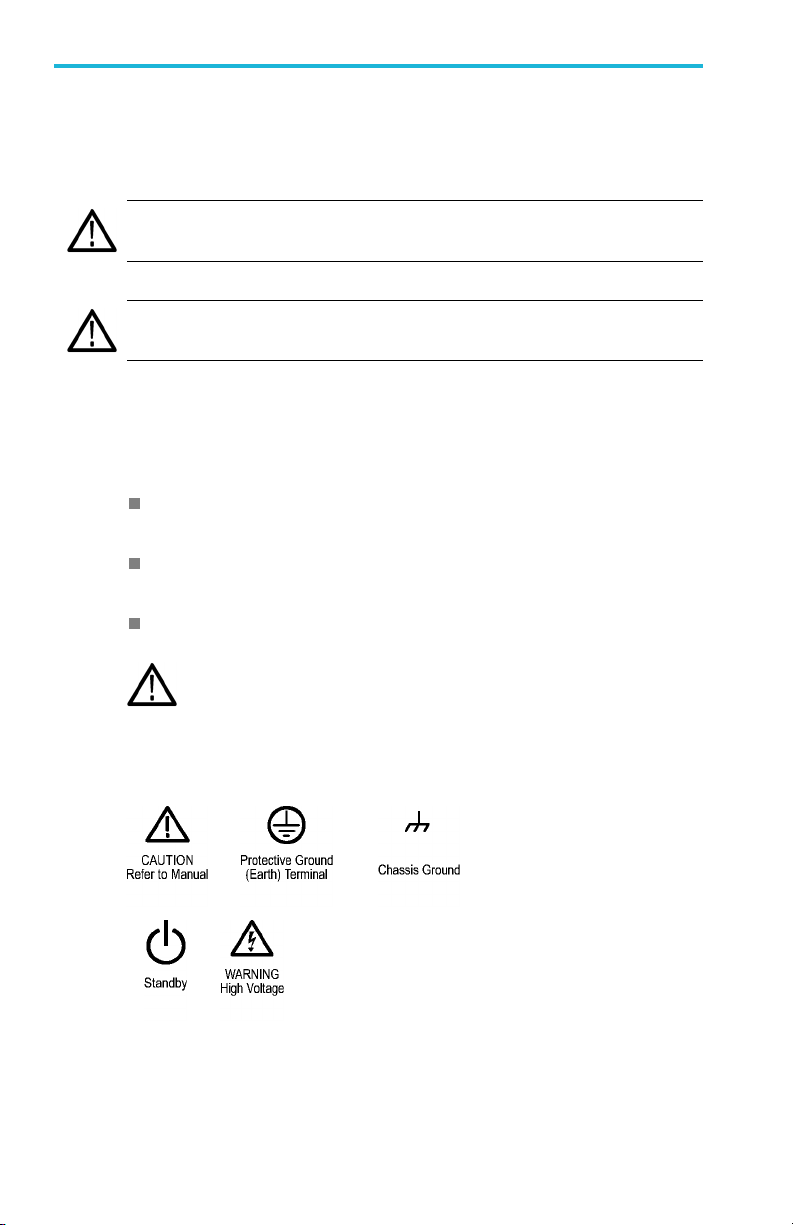
Symbols and terms on the product
These terms may appear on the product:
DANGER indicates an injury hazard immediately accessible as you
read the marking.
WARNING indicates an injury hazard not immediately accessible
as you read the marking.
CAUTION indicates a hazard to property including the product.
When this symbol is marked on the pro duct, be sure to consult
the manual to find out the nature of the potential hazards and
any actions which have to be taken to avoid them. (This symbol
may a lso be used to refer the user to ratings in the manual.)
The following symbol(s) may appear on the product:
x TDS3000C Series Oscilloscopes User Manual
Page 17

Compliance information
This section lists the EMC (ele
environmental standards with which the instrument complies.
EMC compliance
EU EMC Directive
Meets intent of Directive 2014 /30/EU for Electromagnetic
Compatibility. C
specifications as listed in the Official Jo urnal of the European
Communities:
EN 61326-1, EN 61326-2-1. EMC requirements for electrical equipment
for measurement, control, and laboratory use.
CISPR 11. Radiated and conducted emissions, Group 1, Class A
ctromagnetic compliance), safety, and
ompliance was demonstrated to the following
1234
IEC 61000-4-2. Electrostatic discharge immunity
IEC 61000-4-3. RF electromagnetic field immunity
IEC 61000-4-4. Electrical fast transient/burst immunity
IEC 61000-4-5. Power line surge immunity
IEC 61000-4-6. Conducted RF immunity
IEC 61000-4-11. Voltage dips and interruptions im munity
EN 61000-3-2. AC power line harmonic emissions
TDS3000C Series Oscilloscopes User Manual xi
6
5
Page 18

Compliance information
EN 61000-3-3. Voltage changes, fluctuations, and flicker
1
This product is intended for use in nonresidential areas only. Use in residential areas
may cause electromagnetic interference.
2
Emissions which exceed the levels required by this standard may occur when this
equipment is connected to a test object.
3
Equipment may not meet the immuni
when test leads and/or test probes are connected due to coupling of electromagnetic
interference onto those leads/probes. To minimize the influence of electromagnetic
interference, minimize the loop area between the unshielded portions of signal and
associated return leads, and keep leads as far away as possible from electromagnetic
disturbance sources. Twisting unshielded test leads together is an effective way to reduce
loop area. For probes, keep the
probe body. Some probes have accessory probe tip adapters to accomplish this most
effectively. In all cases, observe all safety instructions for the probes or leads used..
4
For compliance with the EMC standards listed here, high quality shielded interface cables
that incorporate low impedan
shell should be used.
5
≤3.0 division waveform displacement or ≤6.0 division increase in peak-to-peak noise is
allowed when the instrument is subjected to fields and signals as definedintheIEC
61000-4-3 test.
6
≤1.5 division waveform displacement or ≤2.0 division increase in peak-to-peak noise is
allowed when the instrument is subjected to fields and signals as definedintheIEC
61000-4-6 test.
ty requirements of applicable listed standards
ground return lead as short as possible and close to the
ce connection between the cable shield and the connector
Australia / New Zealand Declaration of Conformity – EMC
Complies with the EMC provision of the Radiocommunications Act per
the following standard, in accordance with ACMA:
CISPR 11. Radiated and Conducted Emissions, Group 1, Class A,
in accordance with EN 61326-1 and EN 61326-2-1.
xii TDS3000C Series Oscilloscopes User Manual
Page 19

Safety compliance
This section lists the safety standards with which the product complies
and other safety compliance information.
EU low voltage directive
Compliance was demonstrated to the following specification as listed
in the Official Journal of the European Union:
Low Voltage Directi ve 2014/35/EU.
EN 61010-1. Safety Requirements for Electrical Equipment for
Measurement, Control, and Laboratory Use – Part 1: General
Requirements.
EN 61010-2-030. Safety Requirements for Electrical Equipment
for Measurement, Control, and Laboratory Use – Part 2-030:
Particular requirements for testing and m easuring circuits.
U.S. nationally recognized testing laboratory listing
UL 61010-1. Safety Requirements for Electrical Equipment for
Measurement, Control, and Laboratory Use – Part 1: General
Requirements.
Compliance inform ation
UL 61010-2-030. Safety Requirements for Electrical Equipment
for Measurement, Control, and Laboratory Use – Part 2-030:
Particular requirements for testing and m easuring circuits.
Canadian certification
CAN/CSA-C22.2 No. 61010-1. Safety Requirements for Electrical
Equipment for Measurement, Control, and Laboratory Use – Part 1:
General Requirements.
CAN/CSA-C22.2 No. 61010-2-030. Safety Requirements for
Electrical Equipment f or Measurement, Control, and Laboratory
Use – Part 2-030: Particular requirements for testing and measuring
circuits.
TDS3000C Series Oscilloscopes User Manual xiii
Page 20

Compliance information
Additional compliances
IEC 61010-1. Safety Requirements for Electrical Equipment for
Measurement, Control, and Laboratory Use – Part 1: G eneral
Requirements.
IEC 61010-2-030. Safety Requirements for Electrical Equipment
for Measurement, Control, and Laboratory Use – Part 2-030:
Particular requirements for testing and measuring circuits.
Equipment type
Test and measuring equipment.
Safety class
Class 1 – grounded product.
Pollution degree descriptions
A measure of the contaminants that could occur in the environment
around and within a product. Typically the internal environment inside
a product is considered to be the same as the external. Products should
be used only in the environment for which they are rated.
Pollution degree 1. No pollution or only dry, nonconductive
pollution occurs. Products in this category are generally
encapsulated, hermetically sealed, or located in clean rooms.
Pollution degree 2. Normally only dry, nonconductive pollution
occurs. Occasionally a temporary conductivity that is caused
by condensation must be expected. This location is a typical
office/home environment. Temporary condensation occurs only
when the product is out of service.
Pollution degree 3. Conductive pollution, or dry, nonconductive
pollution that becomes conductive due to condensation. These
are sheltered locations where neither temperature nor humidity
is controlled. The area is protected from direct sunshin e, rain, or
direct wind.
Pollution degree 4. Pollution that generates persistent conductivity
through conductive dust, rain, or snow. Typical outdoor locations.
xiv TDS3000C Series Oscilloscopes User Manual
Page 21

Compliance inform ation
Pollution degree rating
Pollution degree 2 (as defined in IEC 61010-1). Rated for indoor, dry
location use only.
IP rating
IP20 (as defined in IEC 60529).
Measurement and overvoltage category descriptions
Measurement terminals on this product may be rated for measuring
mains voltages from one or more of the following categor ies (see
specific ratings marked on the product and in the manual) .
Category II. Circuits directly connected to the building wiring at
utilization points (socket outlets and similar points).
Category III. In the building wiring and distribution system.
Category IV. At the so urce of the electrical supply to the building .
NOTE. Only mains power supply circuits have an overvoltage category
rating. Only measurement circuits have a measurement category ra ting.
Other circuits within the product do not have either rating.
Mains overvoltage category rating
Overvoltage
TDS3000C Series Oscilloscopes User Manual xv
category II (as defined in IEC 61010-1).
Page 22

Compliance information
Environmental considerations
This section provides information abou t the environmental impact of
the product.
Product end-of-life handling
Observe t he following guidelines when recycling an instrument or
component:
Equipment recycling. Pro duction of this equipment required the
extraction and use of nat
substances that could be harmful to the environm ent or human health
if improperly handled at the product’s end of life. To avoid release of
such substances into th
resources, we encourage you to recycle this product in an appropriate
system that will ensure that most of the materials are reused or recycled
appropriately.
Battery Recycling. This product might contain an optional lithium ion
(Li-ion) rechargeable battery, which must be recycled or disposed of
properly.
ural resources. The equipment may contain
e environment and to reduce the use of natural
Lithium-Ion batteries are subject to disposal and recycling
regulations that vary by co
and follow your applicable regulations before disposin
battery. Contact
for U.S.A. and Canada,
rganization.
o
Many countries prohibit the disposal of waste electronic equipment
in standard waste receptacles.
Place only discharged batteries in a battery collection container.
Use electrical tape or other approved covering over the battery
connection points to prevent short circuits.
xvi TDS30 00C Series Oscilloscopes User Manual
Rechargeable Battery Recycling Corporation
untry and region. Always check
g of any
or your local battery recycling
Page 23

Compliance inform ation
Transporting Batteries
The capacity of the optional lithium ion battery pack is under 100 Wh.
The battery meets the applicable requ iremen ts of UN Manual of Tests
and Cr iter ia Part III Section 38.3. As shipped from Tektronix, the
battery quantity is under the limit for shipment according to Section II
of the relevant Packing Instructions from the IATA Dangerous Goods
Regulations. Consult your air carrier for applicability and determ i nati on
of any s pecial lithium battery transportation requirements.
Always check all applicable local, national, and international
regulations before transporting a L ith ium-Ion battery.
Transporting an end-of-life, damaged, or recalled battery may, in
certain cases, be specifically limited or prohibited.
The battery pack must be adequately protected against short-circuit
or damage during transport.
TDS3000C Series Oscilloscopes User Manual xvii
Page 24

Compliance information
xviii TDS3000C Series Oscilloscopes U ser Manual
Page 25

Preface
This manual contains operatin
Digital Storage Oscilloscopes. The m anual consists o f the following
chapters:
The Get ting Started chapter briefly describes features of the
oscilloscope and provides installation instructions.
The Application Examples ch apter provides examples on how to
solve a variety of measurement problems.
The Reference chapter describes the selections or available range of
values for each option.
The Appendix A: Specifications chapter includes electrical,
environmental, and physical specifications for the oscilloscope, as
well as certificatio
The Appendix B: Factory Setup chapt e r contains a list of the menus
and controls with
when you push the Save/Recall front-panel button, and then the
Recall Factory Setup screen button.
The Appendix C: Accessories chapter briefly describes standard
and optional accessories.
The Appendix D: Probe Ba sics chapter provides basic information
on the P3010 and the P6139A probes, and o n other probes.
The Appendix E: Cleaning chapter describes how to take care of
the oscilloscope.
the default settings that the oscilloscope recalls
g information for the TDS3000C Series
ns and compliances.
The Appendix F: Ethernet Setup chapter describes how to set up
the oscilloscop e for printing through the network, and remote
programm
TDS3000C Series Oscilloscopes User Manual xix
ing.
Page 26

Preface
Preventing Electrostatic Damage
CAUTION. Electrostatic discharge (ESD) can damage components in
the oscilloscope and it s accessories. To prevent, ESD, observe these
precautions when directed to do so.
Use a Ground Strap. Wear a grounded, antistatic wrist strap to discharge
the static voltage from your body wh ile installing or removing sensitive
components.
UseaSafeWorkArea. Do not use any devices capable of generating or
holding a static charge in the work area where you install or remove
sensitive components. Avoid handling sensitive components in areas
that have a floor or benchtop su rface capable of generating a static
charge.
Handle Components Safely. Do not slide sensitive components over
any surface. Do not touch exposed connector pins. Handle sensitive
components as little as possible.
Transport and Store Carefully. Transport and store sensitive components
in a static-protected bag or container.
xx TDS3000C Series Oscilloscopes User Manual
Page 27

Preface
Firmware Updates Through the Internet
If a newer version of firmware becomes available, you can use the
Internet and a USB flash drive to update your oscilloscope.
To update the firm ware, follow these steps:
From your computer, access the Web site and check if a newer
1.
v
ersion of oscilloscope firmware is available.
If there is a newer version of firmware, download the firmware file
from the web page. Unzip and copy the tds3000c.img file into the
root folder of a USB flash drive.
2. Power off your oscilloscope.
3. Insert the USB flash drive into the flash drive port on the front of
the oscilloscope.
4. Power on your oscilloscope.
5. When prompted, p ush the OK Load New Firmware menu button
to start the firmware load process.
NOTE. Do not power off the oscilloscope or remove the USB flash drive
until the oscilloscope finishes installing the firmware.
6. Wait for the os
7. When prompted, remove the USB flash drive.
8. Push the Utility front-panel button.
9. Push t he Ve r
firmware version number.
10. Confirm th
TDS3000C Series Oscilloscopes User Manual xxi
cilloscope to reboot itself.
sion bottom button. The oscilloscope displays the
at the version number matches that of the new firmware.
Page 28

Preface
xxii TDS3000C Series Oscilloscopes User Manual
Page 29

Getting Started
In addition to a product and fea
the following topics:
How to perform a quick functio
passive probes, compensate the signal path, and set the time and
date
How to install the power cord, battery pack, and operate the
oscilloscope safely with battery power
How to install application modules and the comm unicatio n module
Howtousethemenusyst
How to identify the oscilloscope c o ntrols and connectors
Initial Setup
The follow ing procedures describe how to quickly verify that the
oscilloscope is
passive probes using the built-in com p e nsatio n signal, run the signal
path compensation (SPC) routine for maximum signal accuracy, and
set the time an
You should perform all initial setup procedures the first time you
use the oscil
ture descriptio n, this chapter covers
nal check, install and compensate
em
powering up and functioning correctly, compensate
d date.
loscope.
You should perform the probe compensation procedure whenever
you attach a
You should run the signal path compensation routine whenever the
ambient t
TDS3000C Series Oscilloscopes User Manual 1
passive probe for the first time to any input channel.
emperature changes by 10 °C (18 °F) or more.
Page 30
Getting Started
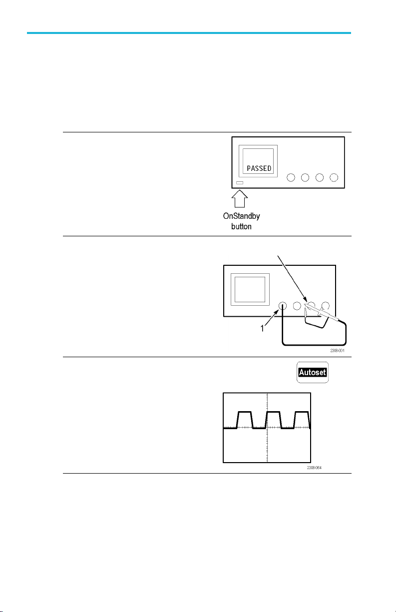
Functional Check
Perform this qu ick functional check to verify that your oscilloscope is
operating correctly.
1. Connect the oscilloscope power
2. Power on the oscilloscope.
cable. (See page 10.)
Wait for the confirmation that all self
tests have passed.
3. Connect the oscilloscope probe to
channel 1. Atta ch the probe tip and
referenceleadtotheProbe Comp
connectors.
4. Push the Autoset button. You
should see a square wave in the
display (approximately 5 V at
1kHz).
Probe Comp
2 TDS3000C Series Oscilloscopes User Manual
Page 31

Getting Started
Probe Compensation
Perform this adjustment to match your pro be to the input channel. This
should be done w h enever you attach a passive probe for the first time to
any input channel.
1. Connect the oscilloscope probe
to channel 1. Attach the probe tip
and reference lead to the Probe
Comp connectors, then push
Autoset.
If us ing the probe hook-tip, ensure
a proper connection by firmly
twisting the tip onto the probe.
2. Check the shape of t
waveform.
3. If necessary, adjust your probe.
he displayed
Probe C omp
Over compensated
Under compensated
Compensated correctly
Autoset button
NOTE. See Appendix D: Probe Basics for more information about the
probes provided with your oscilloscope.
TDS3000C Series Oscilloscopes User Manual 3
Page 32

Getting Started
Signal Path Compensation (SPC)
The SPC routine optimizes the oscilloscope signal path for maximum
measurement accuracy. You can run the routine anytime but you should
always run the routine if the ambient temperature changes by 10 °C
(18 °F) or more.
To compensate the signal path, follow these steps:
1. Disconnect any probes or cables from the channel input connectors.
2. Push the Utility button.
3. Push the System screen button to select Cal .
4. Push the Signal Path screen button.
5. Push OK Compensate Signal Path. This procedure takes several
NOTE. The signal path compensation does not include calibration to the
probe tip.
Adjusting the Oscilloscope Time and Date
minutes t o complete.
To set your oscilloscope to the cu rr ent date and time, follo w these steps:
1. Push the Utility button.
2. Push the System bottom button to select Config.
3. Push the Set D ate & Time bottom button. Use the side menu
buttons to set the date and time values.
4. Push the OK Enter Date/Time side button to set the oscilloscope
date and time.
4 TDS3000C Series Oscilloscopes User Manual
Page 33

Product and Feature Description
The TDS3000C series oscilloscopes consist of the following models:
Model Channels Bandwidth Maximum
TDS3012C
TDS3014C
TDS3032C
TDS3034C
TDS3052C
TDS3054C
Acquisition Features
WaveAlert Waveform Anomaly Detection. This feature autom atically
detects anomalous waveforms by comparing the current waveform to
the previous waveform. WaveAlert sets how the oscilloscope responds:
stop on anomaly, beep on anomaly, and save anomalous waveform to a
USB flash drive. It's useful for capturing signal glitches and intermittent
waveform errors. (See page 69.)
2100MHz
4100MHz
2300MHz
4300MHz
2500MHz
4500MHz
Getting Started
1.25 GS/s
1.25 GS/s
2.5 GS/s
2.5 GS/s
5GS/s
5GS/s
Separate Digitizers. This feature ensures accurate timing measurements
with separate digitizers for each channel. Each digitizer can sample at
up to the maximum sample rate; the acquisition on all channels is always
concurrent to provide full single-shot bandwidth on each channel.
Normal Acquisition. This feature acquires 10,000 point waveforms to
capture horizontal detail, and then you can use the zoom
function to
analyze the detail. (See p age 67.)
Fast Trigger Acquisitio n. This feature acquires up to 3,400 waveforms
per second (500 point mode) so you can see rapidly ch anging signals or
intermittent signal irregularities. (See page 67.)
Pretrigger. You can capture signals that occur before the trigger point.
You can position the trigger point at the beginning of the acquisition, at
the end, or at any location in between. (See page 81.)
TDS3000C Series Oscilloscopes User Manual 5
Page 34

Getting Started
Delay. You can also delay the acquisition sothatitstartsafterthetrigger
point. Use delay when you want to acquire the signal at a specifictime
after the trigger point. (See page 82.)
Peak Detect. This feature allows you to see pulses as narrow as
1 ns even at the slower time base settings. Peak Detect helps you see
noise and glitches in you r signal. (See page 65.)
Signal Processing Features
Average. You can apply averaging to your signal to remove uncorrelated
noise and improve measurement accuracy. (See page 66.)
Envelope. You can use envelope to capture and display the maximum
variation of a signal. (See page 65.)
Waveform Math. You can use waveform math to add, subtract, multiply,
or d ivide waveforms. For example, you can use math to analyze
differential signals or to calculate a power waveform. (See page 88.)
FFT Analysis. You can use FFT (Fast Fourier Transform) m easurem ents
to convert a time-domain signal into its frequency components for
analysis. (See page 89.)
Display Features
Color LCD Display. You can identify and differentiate w aveform s easily
with color coding. Waveforms, readouts, and buttons are color matched
to increase productivity and reduce operating errors. (See page 76.)
Digital Phosphor. A Digital Phosphor Oscilloscope can clearly display
intensity modulation in yo ur signals. The oscilloscope automatically
overlays subsequent acquisitions and then decays them to simulate the
writing and decay of the phosphor in the CRT of an analog oscilloscope.
This feature results in an intensity-graded waveform display that shows
the information contained in the intensity modulation. (See page 61.)
Signal Preview. You can use the preview feature to opt
settings when setting up a single-shot acquisition. As you adjust the
controls, the adjustments modify the current acquisition to show a
preview of how the next acquisition should appear. (
6 TDS3000C Series Oscilloscopes User Manual
imize the control
Seepage63.)
Page 35

Getting Started
Measurement Features
Cursors. You can use cursors to take simple vo ltag e , time, and
frequency measurements. (See page 70.)
Automatic Measurements. You can choose from a list of automatic
waveform measurements. (See page 101.) You can customize the
measurements by changing reference levels or by adding measurement
gating. (See page 97.)
XY Waveform Cursors. You can use cursors to take measurements on XY
waveforms. (See page 73.)
Trigger Features
Dual Tr
iggers.
You can use the main (A ) trigger system alone or add the
B trigger to capture more complex events. You can also use the A and
B triggers together to set up a wait-for-time or wait-for-events trigger.
age 113.)
(See p
Logic Triggers. You can trigger on a Boolean condition between two
signals. You can use logic triggers to analyze problems in digital
circuits, or s ynchronous state machines. (See p age 121.)
Pulse Triggers. You can trigger on a signal that meets a timing or
threshold condition. You can use pulse triggers to analyze problems in
digital circuits, with bus contention, or in bus transceivers, transmission
lines, and op-amp circuits. (See page 128.)
Video Trigger. You can trigger on video fields or lines to see a stable
display of standard video signals. (See page 135.)
Alternating Trigger. You can sequentially use each active channel as
a trigger source, from the lowest-numbered active channel to the
highest-numbered active channel. (See page 119.)
Built-In External Trigger. All models have an external trigger input.
Four-channel models ha ve the external trigger connector on the back
of the oscilloscope. Two-channel models have the external trigg er
connector on the front panel.
TDS3000C Series Oscilloscopes User Manual 7
Page 36

Getting Started
Convenience Features
e*Scope Web-based Remote Control. You can access your TDS3000C
oscilloscope through the Inter
world. (See page 149.)
Built-in Ethernet. You can connect your TDS3000C oscillosco pe to a
network or the Internet using the built-in 10BaseT Ethernet port, for
e*Scope access or printing screen images to network printers. (See
page 185.)
Autoset. You can use A u toset to quickly set up the vertical, horizontal,
and trigger controls for a usable display. (See page 60.)
Scope QuickMenu. You can use the built-in Scope QuickMenu for
simplified oscilloscope operation. (See page 26.)
net, from across a room to across the
Single Sequence.
One button sets the trigger parameters to the correct
settings for a single-shot acquisition (or single-sequence acquisition).
(See page 60.)
USB Flash Drive Port. You can use a USB flash drive to store and recall
waveforms and setups, as well as upgrade the oscilloscope firmware and
install new features. (See page 107.)
Probe Support. You can use the standard probes or choose an optional
probe for a specific application. Appendix D provides information and
limitatio
Multilingual User Interface. On-screen menus and messages are in 11
ns. (Seepage173.)
languages. (See page 137.)
8 TDS3000C Series Oscilloscopes User Manual
Page 37

Optional Features
Application Modules. You can install application modules to add new
test and measurement features.
Communication Module. You can install the communication module to
add RS-232, GPIB, and VGA ports for remote programmability, or to
display the oscillosco pe screen on a monitor. (See page 15.)
Battery Po wer. You can install a rechargeable Lithium-Ion battery pack
(TDS3BATC) to use t he o sc
Operating Positions
Getting Started
(See page 169.)
illoscope without line power. (See page 10.)
Use the handle and fe
operating position.
et to place the oscilloscope in a co nven ient
TDS3000C Series Oscilloscopes User Manual 9
Page 38

Getting Started
Connecting Power
You can operate the oscilloscope from a mains supply with line
voltage between 100 V
47 Hz and 440 Hz. The oscillo sco pe is grounded through the power
cord grounding connector. The line fuse is internal and is not operator
replaceable.
Using Battery Power
You can operate the oscilloscope c ontinuously for ap proximately three
hours from the optional rechargeable TDS3BATC battery pack. A
triangle i c on in the displ ay
power-plug icon
icon
off automatically when the battery runs low; the screen may turn white
a few minutes before t he automatic shutd own .
Refer to the Environmental Considerations for in form ation about p roper
battery disposal. (See page xvi, Environmental considerations.)
shows the ch arge level in the battery. The oscilloscope turns
and 240 VAC(± 10%) and frequency between
AC
shows whe n the battery is in use, a
shows when line power is connected, and a gauge
10 TDS3000C Series Oscilloscopes User Manual
Page 39

Getting Started
Operating Safely with Battery Power
WARNING. To avoid electric shock, connect the rear-panel ground terminal
to earth ground when operating the oscilloscope from battery p ower.
For safe operation, the oscilloscope chassis should always remain at
earth ground potential. Without a connection between the chassis and
earth ground, you can receive a shock from exposed metal on the
chassis if you connect an input to a hazardous voltage (>30 V
>42 V
). To protect yourself against possible shock, you can attach the
pk
Tektronix-supplied grounding wire from the terminal on the rear panel
to earth ground. If you use a different grounding wire, it must be at
least 18 gauge.
RMS
,
If you choose not to attach the grounding w ire, you are not protected
against electric shock if you connect the oscilloscope to a hazardous
voltage. You can still use the oscilloscope if you do not connect a signal
greater than 30 V
(42 Vpk) to the probe tip, the BNC connector
RMS
center, or the common lead. Ensure that all probe common leads are
connected to the sam e voltage.
WARNING. Hazardous volta ges may exist in unexpected places due to faulty
circuitry in the device under test.
CAUTION. When operating the oscilloscope on b
a grounded device, such as a printer or compute
the oscilloscope's grounding wire is conn
attery power do not connect
r, to the oscilloscope un less
ected to the earth ground.
TDS3000C Series Oscilloscopes User Manual 11
Page 40

Getting Started
Installing the Battery
To install the optional battery pack, follow these steps:
1. Open the battery compartment door on the rear panel.
2. Remove the accessory tray.
3. Slide the battery into the compartment and press it in from both
Battery door (opened)
sides until you hear the latches click.
4. Press on both sides of the battery compartment door to snap it
closed.
12 TDS3000C Series Oscilloscopes User Manual
Page 41

Getting Started
To remove the battery, follow these steps:
1. Open the battery compartment door.
2. Raise the handles on each side of the battery and use them to pull
the battery out of the os cill oscope.
Maximizing Operating Time
To max imiz e t
battery charge, consider doing these things:
Reduce the
Disconnect unused active probes
Only use passive probes
TDS3000C Series Oscilloscopes User Manual 13
he time that the oscilloscope can operate from a full
display backlight intensity (See page 75.)
Page 42

Getting Started
Charging the Battery
The battery charges automatically when the oscilloscope is connected to
line power. You can also charge the battery with the optional external
charger (TDS3CHG).
Configuration Typical charging time
Battery charging in oscilloscope with oscilloscope
turned on or off
Battery charging with TDS
NOTE. For optimal performance, charge the battery before using it for the
first time or after prolonged storage.
Refer to the TDS3BATC Rechargable Battery Pack Instructions (Tektronix
part number 071-0900-04) for information on storage and Battery
Maintenance Guidelines.
3CHG external charger
32 hours
6 hours
14 TDS3000C Series Oscilloscopes User Manual
Page 43

Installing an Application Module
CAUTION. To avoid damage to the oscilloscope or application module,
observe the ESD precautions. (See page xx.)
Optional application modules are av a ilab le to extend the capability of
your oscilloscope. You can install up to four application modules at
one time. A pplication modules can g o into the two slots with w ind ows
in the upper right corner of the front panel. Two additional slots are
directly behind the two you can see.
Refer to the TDS3000, TDS3000B, and TDS3000C Series Application
Module Installation Manual that came with your application module for
instructions on installing and testing an application module.
NOTE. If you remove an application module, the features provided by the
application module become unavailable. You can reinstall the module to
restore the features.
Installing the Communication Module
Getting Started
CAUTION. To avoid damage to the oscilloscope or communication module,
observe the ESD precautions. (See page xx.)
To install the optional communications module, follow these steps:
1. Turn the oscilloscope power off.
2. Press down on the latching tab to remove the blank cover.
3. Slide the communication module into the compartment until the
internal connectors are seated and the latchin g tab locks.
4. Turn the power on. The communication module is now ready for
your use.
TDS3000C Series Oscilloscopes User Manual 15
Page 44

Getting Started
To remove a communication module, follow th ese steps:
1. Turn the o scilloscope power off.
2. Press down on the latching tab and then use a small screwdriver to
Latching tab
alternately pry out the sides of the comm unication module.
3. Slide out the communication module and store it in an ESD-shielded
bag. Install the blank cover.
Communication
port For more information, see
GPIB
RS-232
VGA Specifications for the I/O ports in Appendix A in this
The TDS3000, TDS3000B, and TDS3000C Series
Digital Phosphor Oscilloscopes Programmer Manual,
and Hard Copy in this user manual. (Se e page 78.)
user manual.
16 TDS3000C Series Oscilloscopes User Manual
Page 45

Front-Panel Menus and Controls
The front panel has buttons and c o ntrols for the functions you use most
often. The front panel h as menus to access more specialized functions.
Using the Menu System
To use the menu system, follow these steps:
1. Push a front-panel menu button to display the menu you want to use.
Getting Started
TDS3000C Series Oscilloscopes User Manual 17
Page 46

Getting Started
2. Push a bottom screen button to select a menu item. If a pop-up
3. Push a side screen button to choose a menu item. If the menu item
menu appears, continue to push the screen button to select an item
from the pop-up menu.
contains more than one c
to ma ke the choice.
hoice, push the side screen button again
18 TDS3000C Series Oscilloscopes User Manual
Page 47

Getting Started
4. Certain menu choices require you to set a numerical value to
complete the setup. Use the general purpose knob to adjust
the parameter value. Push the Coarse buttontomakelarger
adjustments.
Using the Menu Buttons
You can use the menu buttons to perform many functions in the
oscilloscope.
1. Meas. Perf
2. Cursor. Activates the cursors.
3. Save/Recall. Saves and recalls setups and waveforms to memory or
aUSBflash drive.
4. Display. Changes the appearance of waveforms and the d isplay
screen.
TDS3000C Series Oscilloscopes User Manual 19
orms automated measurements of waveforms.
Page 48

Getting Started
5. QuickMenu. Activates QuickMenus such as the built-in Scope
6. Utility. Activates the s ystem utility functions, su c h as s el ecting
QuickMenu.
a language.
7. Vertical Menu. Adjusts the scale, position, and offset of waveforms.
Sets the input parameters.
8. Trigger Menu. Adjusts the trigger functions.
9. Acquire Me
nu. Sets the acquisition modes and horizontal
resolution, and resets the delay time.
20 TDS3000C Series Oscilloscopes User Manual
Page 49

Getting Started
Using the Dedicated Controls
These dedicated buttons and controls generally control waveforms and
cursors without the use of menus.
1. Coarse. Causes the general purpose knob and position knobs to
make adjustments more quickly.
2. Select. Toggles between the two cursors to select the active cursor.
3. General purpose kno b. Moves the cursors. Sets numerical
parameter values for some menu items. Push the Coarse button to
make adjustments quickly.
4. Vertical Position. Adjusts the vertical position of the selected
waveform. Push the Coarse button to make adjustments more
quickly.
TDS3000C Series Oscilloscopes User Manual 21
Page 50

Getting Started
5. Horizontal Position. Adjusts the trigger point location relative
6. Trigger Level. Adjusts the trigger level.
7. Run/Stop. Stops and restarts acquisition.
8. Single Seq. Sets acquisition, display, and trigger parameters for a
9. Set To 50%. Sets the trigger level to the midpoint of the waveform.
10. Autoset. Automatically sets the vertical, horizontal, and trigger
11. Force Trig. Forces an immediate trigger event.
12. Waveform Intensity. Controls waveform int e nsity.
13. B Trig. Activates the B trigger. Changes the Trigger menu to set
14. Delay. Enables delayed acquisition relative to the trigger event.
15. Horizontal Scale. Adjusts the horizontal scale factor.
to the acquired waveforms. Push the C oarse button to make
adjustments quickly.
single-shot (single-sequence) acquisition.
controls for a usable display.
the B-t rigger parameters.
Use horizontal Position to set the amount of delay.
16. Horizontal Zoom. Splits the screen and magnifies the current
acquisition horizontally.
17. Waveform Off. Removes selected waveform from the display.
18. Vertical Scale. Adjusts selected waveform vertical scale factor.
19. 1, 2, (3, 4,) Math. Displays a waveform and chooses the selected
waveform. Ref shows the referen ce waveform menu.
22 TDS3000C Series Oscilloscopes User Manual
Page 51

Getting Started
20. Hard copy. Initiates a har
d copy using the port selected in the
Utility menu.
21. Power switch. Turns pow
er to on or standby. Power-up time
varies from about 15 seconds to 45 seconds, depending on the
oscilloscope internal calibration process.
22. Wrist-strap ground. Connect a wrist strap when working with
ESD-sensitive circuits. This connector is not a safety ground.
NOTE. The wrist-st rap ground terminal is only a ground when the
oscilloscope is connected to earth ground. When operating from a battery,
connect the grounding wire to earth ground to ensure th e terminal is at
ground.
23. USB Flash Drive port.
24. Menu Off. Clears menu from the display.
TDS3000C Series Oscilloscopes User Manual 23
Page 52

Getting Started
Identifying Items in the Display
The following items may appear in the display; n ot all items are visible
at any given tim e. Some readouts move outside the graticule area when
menus are turned off.
1. Waveform baseline icons show the zero-volt level of the waveforms
(ignoring the effect of offset). The icon colors correspond to the
waveform colors.
2. Acquisition readout shows when acquisition is running, stopped, or
when acquisition preview is in effect.
3. Trigger position icon shows the trigger location in the waveforms.
4. Expansion point icon shows the point that the horizontal scale
expands and compresses aro und .
5. Waveform record icon shows the trigger location relative to the
waveform record. T he line color corresponds to the selected
waveform color.
6. Trigger status readout show trigger status.
24 TDS3000C Series Oscilloscopes User Manual
Page 53

Getting Started
7. Trigger level icon shows the trigger level on the waveform. The
icon color correspond s to the trigger source channel color.
8. Cursor and measurement readouts show results and messages.
NOTE. Waveforms that extend beyond the screen (overrange) will display a
message in the measurement readout ("clipping"). This indicates that the
numerical readout is an invalid value. Adjust the v ertical scaling to ensure
the readout is valid.
9. Trigger readouts show the trigger sources, slopes, and l evels, and
position.
10. Readout shows th e delay setting or the trigger location within the
record.
11. Horizontal readout shows the main or z o om time/division.
12. Auxiliary waveform readouts show the vertical and horizontal scale
factors of the math or reference waveforms.
13. Channel readouts show the channel scale factor, coupling, input
resistance, bandwidth limit, and invert status.
14. Triangle i con with the battery icon indicates a battery is installed
and battery power is in use. The battery icon sho ws the approximate
charge level of the battery. (See page 11, Operating Safely with
Battery Power.)
15. Power-plug icon wit h the batter y icon indicates a battery is instal led
but line power is in use. The battery may be charging. The battery
icon shows the approximate charge level.
TDS3000C Series Oscilloscopes User Manual 25
Page 54

Getting Started
Using QuickMenus
The QuickMenu feature simplifies the use of the oscil loscop e. W hen
you push the QuickMenu button, a set of frequently used menu
functions show on the display. Then, push the screen buttons around the
display to operate the QuickMenu. The Reference chapter has general
instructions on how to operate QuickM enu s. (See page 103.)
Using the Scope QuickMenu. Scope is one type of QuickMenu that you
can use to control the basic oscilloscope functions. You can perform
many tasks without using the regular menu system. If you need to use a
function that is not contained in the Scope QuickMenu, push the button
you would normally push to access that function. For example, if you
want to add an automatic measurement, push the Meas button to set up
the measurement. Then, push the QuickMenubuttontoreturntothe
Scope QuickMenu with the measurement also in the display.
1. Edge Trigger controls. Push these screen buttons to set trigger
parameters for edge trigger.
2. Trigger controls if either B trigger or video trigger is selected. Logic
and Pulse trigger controls are not available through the QuickMenu.
26 TDS3000C Series Oscilloscopes User Manual
Page 55

Getting Started
3. Cursor control. Push this screen buttontoturnoncursorsandselect
the cursor type. Push the Select button to toggle between the two
cursors to select the active cursor. Use the general purpose knob to
move the active cursor.
4. Acquisition controls. Push these screen buttons to set acquisition
parameters.
5. Channel vertical controls. Push these screen buttons to set vertical
controls for the selected channel. Use the channel 1, 2, 3, 4, and the
Math and Ref buttons to select th e channel you want to control.
6. Vertical controls if either the math waveform or a reference
waveform is selected.
7. Menu. Push this screen button to select a specific Quick Menu
display if more than one is available.
NOTE. Items in the Scope QuickMenu not mentioned above are also
contained in the regular display. (See page 24.)
Some optional application packages include a
Other QuickMenus
.
custom QuickMenu display. Those QuickMenus contain specific
features that are important for the application.
TDS3000C Series Oscilloscopes User Manual 27
Page 56

Getting Started
Front-Panel Connectors
1. Probe Comp. Square wav e signal source to compensate probes.
2. 1, 2, (3, 4). Channel inputs with TekProbe interface.
3. Ext Trig. External trigger input with TekProbe interface
(two-channel models only). External trigger input specifications
are in Appendix A.
28 TDS3000C Series Oscilloscopes User Manual
Page 57

Rear-Panel Connectors
Getting Started
1. Power input. Attach to an AC power line with integral safety
ground.
2. Communication Module compartment. Install the optional
communication module.
3. Ethernet port. Connects the oscilloscope to a 10BaseT local area
network.
4. Ext Trig. External trigger input with TekProbe interface
(four-channel models only). External trigger input specifications
are in Appendix A.
TDS3000C Series Oscilloscopes User Manual 29
Page 58

Getting Started
5. Ground terminal. Connect to earth ground when using battery
power. (See page 11, Operating Safely with Battery Power.)
6. CAL switch. For use by authorized service personnel only.
Communication Module Connectors
1. GPIB port. Connect to a controller for remote programmability.
2. RS-232 port. Connect to a controller or terminal for remote
programmability or printing.
3. VGA port. Connect to a VGA monitor to display the screen image.
30 TDS3000C Series Oscilloscopes User Manual
Page 59

Application Examples
This chapter presents six common oscilloscope applications:
Taking simple measurements
Analyzing signal detail
Taking FFT measurements
Triggering on a video signal
Capturing a single-shot signal
Saving data to a USB flash drive
Each application example highlights different features of the
oscilloscope and gives you ideas about using the oscilloscope to solve
test problem s.
Taking Simple Measurements
You need to see a signal in a circuit, but you do not know the signal
amplitude or frequency. Connect the oscilloscope to quickly display the
signal and then measure its frequency and peak-to-peak amplitude.
TDS3000C Series Oscilloscopes User Manual 31
Page 60

Application Examples
Using Autoset
To quickly display a signal, follow these steps:
1. Connect the channel 1 probe to th e signal.
2. Push the Autoset button.
The oscilloscope sets vertical, horizontal, and trigger controls
automatically. You can manually adjust any of these controls if you
need to optimize the display of the waveform.
When you are using more than one channel, the autoset function sets the
vertical controls for each channel and uses the lowest-numbered active
channel to set the horizontal and trigger controls.
Selecting Automatic Measurements
The oscilloscope can take au tomatic measurements of most displayed
signals. To measure signal frequency and peak-to-peak amplitude,
follow these steps:
1. Push the Meas button to see the Select Measurement menu.
2. Push the channel 1 button and then push the Select Measurement
for Ch1 screen button.
3. Select the Frequency measurement.
4. Push the more screen button and select the Pk-Pk measurement.
5. Push the Menu Off button.
The measurements show on the screen and update as the signal changes.
32 TDS3000C Series Oscilloscopes User Manual
Page 61

Measuring Two Signals
Application Examples
Youaretestingapie
its audio amplifier. You have an audio generator that can inject a test
signal at the amplifier input. Connect two oscilloscope channels to the
amplifier input and
these measurements to calculate the gain.
ce of equipment and need to measure the gain of
output as shown. Measure both s ignal levels and use
TDS3000C Series Oscilloscopes User Manual 33
Page 62

Application Examples
To display the signals connected to channels 1 and 2, follow these steps:
1. Push the channel 1 and 2 buttons to activate both channels.
2. Push the Autoset button.
To select measurements for the two channels, follow these steps:
1. Push the Meas button to see the Select Measurement menu.
2. Push the channel 1 button and then push the Select Measurement
for Ch1 screen button.
3. Select the Amplitude measurement.
4. Push the channel 2 button and then push the Select Measurement
for Ch2 screen button.
5. Select the Amplitude measurement.
6. Calculate the amplifier gain using the follow ing equations:
34 TDS3000C Series Oscilloscopes User Manual
Page 63

Application Examples
Customizing Your Measurements
In this example you want to verify that the incoming signal to a piece of
digital equipment meets its specifications. S pecifically, the transition
time from a low logic level (0.8 V) to a high logic level (2.0 V) must
be 10 ns or less.
To select the rise time measurement, follow these steps:
1. Push the Meas button to see the Select Measurement menu.
2. Push the channel 1 b
Ch1 screen button.
3. Select the Rise T
Rise time is typically measured between the 10% and 90% amplitude
levels of a sig
uses for rise time measurements. However, in this example you need
to measure the time the signal takes to pass between the 0.8 V and
2.0 V levels.
Yo u can customize the rise time measurement to measure the signal
transition
those reference levels to a specific percent of the signal amplitude or to
a specific level in vertical un its (such as v olts or amperes).
nal; these are the default reference levels the oscilloscope
time between any two reference levels. You can set each of
utton and then the Select Measurement for
ime measurement.
TDS3000C Series Oscilloscopes User Manual 35
Page 64

Application Examples
Setting Refere nce Levels. To set the reference levels t o specific voltages,
follow these steps:
1. Push the Reference Levels screen button.
2. Push the Set Levels in screen button to select units.
3. Push the High Ref screen button.
4. Use the general purpose kn ob to select 2.0 V.
5. Push the Low Ref screen button.
6. Use the general purpose knob to select 800 mV.
The measurement verifies that the transition time (3.842 ns) meets the
specification ( ≤ 10 ns).
36 TDS3000C Series Oscilloscopes User Manual
Page 65

Application Examples
Measuring Specific Events. Nextyouwanttoseethepulsesinthe
incoming digital signal, but the pulse widths vary so it is hard to
establish a stable trigg e r. To look at a snapsh ot of th e digital signal,
follow this step:
1. Push the Single Seq button to cap ture a single acquisition.
Now you want to measure the width of each displayed pulse. You
can use measurement gating to select a specific pulse to measure. To
measure the second pulse, for example, follow these steps:
1. Push the Meas button.
2. Push the channel 1 button and then push the Select Measurement
for C h1 screen button.
3. Select the Po sitive Pulse Width measurement.
4. Push t he Gating screen button.
5. Select Between V Bar Cursors to choose measurem ent gating
using c ursors.
6. Place one cursor to the left and one cursor to the right of the second
pulse.
Theoscilloscopeshowsthewidthmeasurement (160 ns) for the second
pulse.
TDS3000C Series Oscilloscopes User Manual 37
Page 66

Application Examples
Analyzing Signal Detail
You have a noisy signal displayed on the oscilloscope and you need to
know more about it. You suspect that the signal contains much more
detail than you can now see in the display.
38 TDS3000C Series Oscilloscopes User Manual
Page 67

Application Examples
Looking at a Noisy Signal
The signal appears noisy and you suspect that noise is causing problems
in your circuit. To better analyze the noise, follow these steps:
1. Push the Acquire Menu button.
2. Push the Mode bottom button.
3. Select the Peak Detect acquisition mode.
4. Increase the Waveform Intensity control to see the noise more
easily.
Peak detect emphasizes noise spikes and glitches in your signal as
narrow as 1 ns, even when the time base is set to a slow setting.
The Reference chapter has more information about peak-detect and the
other acqui
TDS3000C Series Oscilloscopes User Manual 39
sition modes. (See page 65.)
Page 68

Application Examples
Separating the Signal from Noise
Now you want to analyze the signal shape and ignore the noise. To
reduce random noise in the oscilloscope display, follow these steps:
1. Push the Acquire Menu button.
2. Push the Mode bottom button.
3. Select the Average acquisition mode.
Averaging reduces random noise and makes it easier to see detail in a
signal. In the next example, a ring shows on the rising and falling edges
of the signal when the noise is removed .
40 TDS3000C Series Oscilloscopes User Manual
Page 69

Application Examples
Taking Cursor Measurements
Yo u can use the cursors to take quick measurements on a waveform.
To measure the ring frequency at the rising edge of the signal, follow
these steps:
1. Push the Cursor button.
2. Push the Function screen button.
3. Select VBarscursors.
4. Push the VBarUnitsscreen button.
5. Select 1/seconds (Hz).
6. Place one cursor on the first peak of the ring using the general
purpose k nob .
7. Push the Select button.
8. Place the o ther cursor on the next peak of the ring.
The cursor Δ readout shows the measured ring frequency i s 227 kHz.
TDS3000C Series Oscilloscopes User Manual 41
Page 70

Application Examples
Using Delay
You are analyzing a pulse waveform and use the + Width measurement
to measure the waveform pulse width. You notice that the measurement
is not stable, which implies that there is jitter in the pulse width.
To use delay to see t
1. Push the Delay button.
2. Adjust the horizontal Position control to set the delay close to the
nominal pulse width (210 μs). Push the Coarse buttontomake
delay adjustme
fine tu ne the delay time.
The falling e
When delay is on, the horizontal expansio n point separates from
the trigger point and remains in the center of the screen.
he jitter, follow these steps:
nts more quickly. Push the Coarse button again to
dge of the pulse is now near the center of the screen.
42 TDS3000C Series Oscilloscopes User Manual
Page 71

Application Examples
3. Adjust the horizontal Scale to a faster time base setting and increase
the Waveform Intensit
y to see the jitter in the pulse width.
NOTE. You can toggle the delay function on and off to view signal details at
two different areas of interest.
TDS3000C Series Oscilloscopes User Manual 43
Page 72

Application Examples
Measuring Jitter
To measure the peak-to-peak jitter, follow these steps:
1. Push the Cursor button.
2. Push the Function screen button.
3. Select the VBarscursors.
4. Push the Bring B oth Cursors On Screen screen button to quickly
locate the cursors.
5. Place one cursor at the first falling edge and place the other cursor
at the last falling edge.
6. Read the peak-to-peak jitter in the Δ readout (1.40 μs).
You can also
you select the first cursor, the @ readout displays the minimum pulse
width (210 μs). When you select the second cursor, the @ readout
displays t
44 TDS3000C Series Oscilloscopes User Manual
measure the minimum and maximum pulse widths. When
he maximum pulse width (211 μs).
Page 73

Taking FFT Measurements
Yo u can take FFT measurements to determine if low-level distortion is
present, or to find the s ou rce of noise in a mixed circuit.
Detecting Distortion
A pure sine wave can be input into an amplifier to measur e distortion;
any amplifier distortion will introduce harmonics in the amplifier output.
Viewing the FFT of the output can determine if low -level distortion is
present.
Yo u are using a 20 MHz signal as the amplifier test signal. You would
set the oscilloscope and FFT parameters as listed in the next table.
Control Setting
1 Coupling AC
Acquisition Mode Average 16
Horizontal Resolution
Horizontal Scale
FFT Source Ch1
FFT Vert
FFT Window Blackman-Harris
Scale
Application Examples
Normal (10k points)
100 ns
dBV
In the next figure, the firstcomponentat20MHz(figure label 1) is
urce signal fundamental frequency. The FFT waveform also
the so
shows a second-order harmonic at 40 MH z (label 2), and a fourth-order
harmonic at 80 MHz (label 3). The presence of components 2 and
dicate that the system is distorting the signal. The even harmonics
3in
suggest a possible difference in signal gain on half of the signal cycle.
TDS3000C Series Oscilloscopes User Manual 45
Page 74

Application Examples
Identifying the Source
of Noise
Noise in mixed digital/analog circuits can be easily observed with an
oscilloscope. Howeve
r, identifying the sources of the observed noise
can be difficult.
The FFT waveform di
splays the frequency content of the noise. You
may then be a ble to associate those frequencies with known system
frequencies, such as system clocks, oscillators, read/write strobes,
display signals,
or switching power supplies.
The highest frequency on the example system is 40 MHz. To analyze
the example sig
nal, you would set the oscilloscope and FFT parameters
as listed in the next table.
Control Setting
1 Coupling AC
Acquisition Mode
Horizontal Resolution
Horizontal Scale
Bandwidth 150 MHz
FFT Source Ch1
FFT Vert Scale
FFT Window Hanning
Sample
Normal (10k points)
s
4.00 μ
dBV
46 TDS3000C Series Oscilloscopes User Manual
Page 75

Application Examples
In the next figure, notice the component at 31 MHz (figure label 1). This
coincides with a 31 MHz memory strobe signal in the example system.
There is also a frequency component at 62 MHz (label 2), which is the
second harm onic of the strobe signal.
Triggering on a Vid
Yo u are testing the video circuit in a piece of medical equipment and
need to display th
standard signal. Use the video trigger to obtain a stable display.
eo Signal
e video output signal. The video output is an NTSC
TDS3000C Series Oscilloscopes User Manual 47
Page 76

Application Examples
To trigger on the video fields, follow these steps:
1. Push the Trigger Menu button.
2. Push the Ty p e screen button to select Video.
3. Push the Standard screen button to select 525/NTSC.
4. Push the Trigger On screen button.
5. Select Odd.
6. Adjust the horizontal Scale to see a complete field across the screen.
7. Push the Acquire Menu button.
8. Push the Horizontal Resolution screen button.
9. Select Normal acquisition resolution.
Normal acquisition resolution is the best choice to acquire a video field
signal because the signal contains a great amount of horizontal detail.
If the signal had been noninterlaced, you could choose to trigger on
All Fiel
ds.
48 TDS3000C Series Oscilloscopes User Manual
Page 77

Application Examples
Triggering on Lines. You can also look at the video lines in the field. To
trigger on the lines, follow these steps:
1. Push the Trigger On screen button.
2. Select All Lines.
3. Adjust the horizontal Scale to see a complete video line across
the screen.
NOTE. The optional TDS3VID and TDS3SDI application modules add
new video functions such as a video QuickMenu, video Autoset, trigger on
custom scan rates, trigger on specifi c video lines, vectorscope (vectorscope
supports component v ideo only), video picture, trigger on analog HDTV
signals, and view 601 digital video signals (TSD3SDI only).
TDS3000C Series Oscilloscopes User Manual 49
Page 78

Application Examples
Looking at Modulation. A dedicated video waveform monitor clearly
shows the modulation in a video signal. To see a similar modulation
display on the oscilloscope screen, follow these steps:
1. Start with triggered display of the video lines.
2. Push the Acquire Menu button.
3. Push the Horizontal Resolution screen button.
4. Select Fast Trigger acquisition resolution.
5. Adjust the Waveform Intensity control for the amount of
modulation you want to see.
The oscilloscope now shows signal modulation in shades of intensity
and appears similar to the display of a video waveform monitor or an
analog oscilloscope. Fast trigger acquisitio n resolution is the best choice
to acquire a video line signal with a rapidly changing shape.
50 TDS3000C Series Oscilloscopes User Manual
Page 79

Capturing a Single-Shot Signal
The reliability of a reed relay in a piece of equipment has been poor and
you need to investigate the problem. You suspect that the relay contacts
arc when the relay opens. The fastest you can open and close the relay
is about once per minute so you need to capture the voltage across the
relay as a single-shot acquisition.
To set up for a single-shot acquisition, follow these steps:
1. Adjust the vertical Scale and horizontal Scale to appropriate ranges
for the signal you expect to see.
2. Push the Acquire Menu button.
3. Push the Horizontal Resolution screen button.
4. Select Normal acquisition resolution.
5. Push the Single Seq (single sequence) button.
Application Examples
The Single Seq button sets trigger p aram eters to the correct settings for
a single-shot acquisition.
TDS3000C Series Oscilloscopes User Manual 51
Page 80

Application Examples
Optimizing the Acquisition
The initial acquisition shows the relay contact beginning to open at the
trigger point. This is followed by a large spikes that indicate contact
bounce and inductan ce in the circuit. The inductance can cause contact
arcing and premature relay failure.
Before you take the next acquisition, you can adjust the vertical and
horizontal controls to give you a preview of how the next acqu isition
might appear. As you adjust these controls, the current acquisition
is repositioned, expanded, or compressed. This preview is useful to
optimize the settings before the next single-shot event is captured.
When the next acquisition is captured with the new vertical and
horizontal settings, you can see more detail about the relay contact
opening. You can now see that the contact bounces several times as
it open s.
52 TDS3000C Series Oscilloscopes User Manual
Page 81

Application Examples
Using the Horizontal Zoom Function
If you want to take a close look at a particular spot on the acquired
waveform, use the horizontal zoom function. To look closely at the
point where the relay contact first begins to open, follow these steps:
1. Push the zoom button
2. Use the horizontal Position to place the expansion point close to
where the relay contact begins to open.
3. Adjust the horizontal Scale to magnify the waveform around the
expansion point.
The ragged waveform and the inductive load in the circuit suggest that
the relay contact may be arcing as it opens.
The zoom function works equally well when acquisition is running
or is stopp
display, not the next acquisition.
ed. Horizontal position and scale changes affect only the
.
TDS3000C Series Oscilloscopes User Manual 53
Page 82

Application Examples
Saving Data to a USB Flash Drive
You need to do some work inside a remote site. You expect to use
the oscilloscope to look at signal waveforms, to bring the waveform
information back to the office to complete a report, and to perform
additional analysis. To do this, take along a USB flash drive.
When you need to capture screen images, it may be most convenient
to first save them to a USB flashdrive. OnceontheUSBflash drive,
you can load the screen images into a PC, print hard c opies with a
printer attached to your PC, or import the screen images into desktop
publishing software to produce a report.
Remote site
Similarly, you can also save waveform data on the USB flash drive.
From the flash drive, you can recall waveforms to the oscilloscope
display or you can import the data into spreadsheet and Mathcad
software to perform add itional analysis.
If you have oscilloscope setups that you want to use again, you also
can store them on the USB flash drive. The Reference chapter has
more information on this capability. (See page 104, Save/Recall.)
For information about remote control accessories, see Appendix C:
Accessories.
54 TDS3000C Series Oscilloscopes User Manual
Page 83

Application Examples
Saving Screen Images
While working at the remote site you discover a control signal that you
want to capture periodically to show its long-term variation. You want to
include these waveforms in a report you are preparing back at the office.
Yo ur desktop publishing software can import BMP graphics, so
you decide to use this format for the screen images. To setup this
configuration, follow these steps:
1. Insert a USB flash drive into the U S B flash drive port.
2. Push the Utility button.
3. Push the System bottom button to select Hard Copy.
4. Push t he Format screen button.
5. Select BMP M ono Windows mono image file format (you may
need to push the -more-screen button several times before you
see this choice).
6. Push the Port screen button.
7. Select File to send hard copies to a USB flash drive.
8. Push the hard copy button
The o scilloscope reads the flash drive directory and displays its contents.
You should give files descriptive names so you can
Naming Files
recognize them when you get back to the office. You will be saving
images of the control signal so you decide if CNTRL is a logical target
file name to u
The oscilloscope can append an automatic sequence number to the
target fil
a screen image of the same control signal every five minutes. To set up
the target file name and automatic sequence, follow these steps:
1. Push the File Utilities bottom button.
2. Use the
3. Select the Rename screen button.
TDS3000C Series Oscilloscopes User Manual 55
.
se.
e name. This feature is convenient because you want to capture
general purpose knob to highlight the file TEK?????.BMP.
to save the image.
Page 84

Application Examples
4. Use the screen buttons to clear the existing file name and enter
the new file name CN TRL???.BMP. The question marks are
placeholders for an automatic number sequence from 000 to 999.
5. Push the OK Accept screen button to setup the target base file
name.
6. Push Menu Off to remove the file list from the display.
56 TDS3000C Series Oscilloscopes User Manual
Page 85

Application Examples
Running the Test. To capture the control signal every few minutes,
follow these steps:
1. Display the signal, measurements, and menus as you w ant them
to appear in the screen images.
2. Push the hard copy button
.
3. Repeat step 2 every few minutes until you are finished with the test.
4. When you are finished, push Utility to see the list of sequential
files that have been saved.
The files are labeled with their sequential names, as well as the time
and date each
was created.
TDS3000C Series Oscilloscopes User Manual 57
Page 86

Application Examples
Saving Waveform Data
You find another signal that you want to analyze with a spreadsheet
program back at the office. To save the waveform data on a USB flash
drive, follow these steps:
1. Display the signal on the oscilloscope screen.
2. Push the Save/Recall button.
3. Push the Save Waveform screen button.
4. Select To File.
5. Select Spreadsheet File Format. The default target file,
TEK?????.CSV, is now automatically highlighted.
6. Push the Save To Selected File screen button to save the waveform .
7. Push the File Utilities screen button to see the saved waveform fi le
TEK00000.CSV in the USB flash drive directory.
58 TDS3000C Series Oscilloscopes User Manual
Page 87

Reference
This chapter contains detaile
oscilloscope. The topics in this chapter are arranged by front-panel
button or control group name.
Acquisition Controls
Run/Stop Button
Push the Run/Stop button to stop and start wavefo rm acquisition.
Yo u can also push Run/Stop when you want to resume continuous
acquisition after a single-sequence acquisition. A readout in the top left
corner of the display shows the status of the acquisition.
Acquisition status readout Description
Run: The acquisition is running.
Roll: A roll-mode acquisition is running.
Stop:
PreVu:
While the acquisitio n is running or stopped, you can use these controls
to examine the waveforms:
Channel buttons to select a channel
d information about the operation of the
The acquisition is stopped.
Previewing; waiting for trigger.
Zoom button with horizontal Position and Scale to magnify
waveforms (does not affect the actual time base or trigger position
settings)
Waveform Intensity to adjust gray-scale level
Cursor button to activate cursors to measure waveforms
Meas button to select automatic measurements of waveforms
Hard copy button to print a hard copy
While the acquisition is stopped, you can change the vertical and
horizontal controls to use in the next acquisition. (See page 63, Vert i c a l
and Horizontal Preview.)
TDS3000C Series Oscilloscopes User Manual 59
Page 88

Reference
Single Sequence Button
Push the Single Seq button to execute a single-shot acquisition. T he
function of the S in gle Seq button depends on the acquisition mod e.
Acquisition mode Single Seq function
Sample or Peak De tect One acquisition of each displayed channel is
acquired, concurrently
Envelope N or Average N
When you push the Single Seq button, the oscilloscope does the
following thin gs:
At sweep speeds of 2 0 ms/div and faster, the trigger mode is set
to Norma
l
The trigger sy stem arms and an LED lights next to the Single Seq
button
After the single-sequence acquisition is complete, the acquisition stops
and the light next to the Single Seq button turns off.
Push the Single Seq button again to acquire a new sequence, or push the
Run/Stop button to restart continuo us acquisition.
N acquisitions of each displayed channel are
acquired (N is adjustable with the general
purpose knob)
Autoset Button
Push the Autoset button to automatically adjust the vertical, horizontal,
and trigger controls for a usable display. You can manually adjust any
of these controls if you need to optimize the display.
When you use more than one channel, the autoset function sets the
vertical scale for each channel and positions the channels to prevent
overlapping. The autoset function selects the lowest-numbered channel
in use and then uses that channel to set the horizontal an d trigger
controls.
The autoset function also changes the fo llowing oscilloscope settings:
Acquisition mode is set to Sample
Bandwidth lim it s are set to Full
Zoom is tu
60 TDS3000C Series Oscilloscopes User Manual
rned off
Page 89

Reference
Trigger is set to Auto mode and minimum holdoff
Trigger is set to Edg e type, DC coupling, and rising slop e
B trigger is turned off
XY display format is turned off
Channel 1 is turned on and selected if no active channels are in use
If you push the Autoset button by accident, you can undo it with these
steps:
1. Push the Acquire Menu button.
2. Push the Autoset screen button and then push the Undo Autoset
screen button.
Waveform Intensity
The Waveform I ntensity knob adjusts the intensity of the waveforms in
the display.
The term Digital Pho sphor represents the way t his control simulates the
intensity control of an an a log oscilloscope. At maximum intensity, all
waveform points are displayed at full brightness. As you decrease the
intensity, you can see intensity grading in the waveforms. The brightest
parts of the waveform are the points most frequently acquired; the
dimmer parts represent less frequently acquired points. All points decay
in intensity over time unless the display persistence is set to infinite.
Use a medium intensity setting to get an analog-oscilloscope view
of time-v arying signals and those containing modulation. Use the
maximum intensity setting to view the signals the way most digital
oscilloscopes display them.
Yo u can turn on display persistence to slow or prevent the decay of the
waveform points. With persistence on, you can simulate the fun ction of
an analog storage oscilloscope. (See page 75, Display.)
NOTE. The waveform intensity may change when you change oscillosc ope
acquisition modes or horizontal scale settings. Use the I NTEN SITY knob to
readjust waveform intensity.
TDS3000C Series Oscilloscopes User Manual 61
Page 90

Reference
Acquire Menu
Push the Acq uire Menu button to show the Acquire menu.
Bottom Side Description
Mode
Horizontal
Resolution
Reset
Horizontal
Delay
Autoset
Sample Use for normal acquisition.
Peak Detect Detects glitches and reduces the
possibility of aliasing.
Envelope N
Average N Reduces random or uncorrelated
Fast Trigger (500
points)
Normal (10k points) Acquires 10,000 point waveforms
Set to 0 s
Normal Autoset
Undo Autoset
Captures variations of a signal over
a period of time. (Adjust N with the
general purpose knob.)
noise in the signal display. (Adjust N
with the gen eral purpose knob.)
Acquires 500 point waveforms at a
fast repetition rate.
with more horizontal detail.
Resets the horizontal delay time to
zero.
es the autoset function.
Execut
onal application modules may
(Opti
oices to execute specialized
add ch
set functions.)
auto
Reverts to the settings before the
last autoset.
62 TDS3000C Series Oscilloscopes User Manual
Page 91

Bottom Side Description
WaveAlert
Wfm Anomaly
Detection
On Off
Sensitivity nn.n% Sets the WaveAlert sensitivity. Use
Beep On Anom aly
On Off
Stop On Anomaly
On Off
Hard Copy O
Anomaly
On Off
Wfms To Disk On
Anomaly
On Off
Highlight Entire Wfm
Highlight Anom alies Highlights just the anomalous data
n
Enables or disables the WaveAlert
function. (See page 68, WaveAlert
Waveform Ano m aly Detection .)
the general purpose knob to set
sensitivity from 0% (least sensitive)
to 100% (most sensitive).
When On, the oscilloscope beeps
when it detects a waveform anomaly
on any active channel.
When On, the oscilloscope stops
waveform acquisition when there is a
waveform anomaly on any channel.
The input waveforms and anomalies
remain displayed on the screen.
When On, th
image of th
device or
there is
channel
When On, the oscilloscope saves
the anomalous waveform(s) data to
a file on a USB flash drive.
Highlights the entire anomalous
waveform.
in a waveform.
USB flash drive file when
a waveform anomaly on any
.
Reference
e oscilloscope sends an
e screen to the hard copy
Key Points
Vertical and Horizontal Preview. The vertical and horizontal preview
functions let you change the vertical and horizontal controls while the
acquisition is stopped or while it is waiting for the next trigger. The
oscilloscope rescales and repositions the current acquisition in response
to the new control settings, and then uses the new settings for the next
acquisition.
TDS3000C Series Oscilloscopes User Manual 63
Page 92

Reference
Preview helps you optimize these control set tings before the next
acquisition; this makes it easier to work with signals that are single-shot
or have a low repetition rate. (See page 146, Vertical Preview.) (See
page 86, Horizontal Zo om and Preview.)
While the acquisition is stopped you can make changes to o ther controls,
but those changes will only take affect with the next acquisition. There
is no preview for control changes o ther than the vertical and horizontal
controls.
The preview functions also do not affect automatic measurements,
cursor measurements, or the Math waveform. This data for these
functions is always b ased on the current acquisition. If you rescale
or reposition a channel waveform horizontally, it may not appear
time-correlated to the automatic measurements, cursor measurements,
or the Math waveform.
Acquisition Modes. You can ch oose one of four acquisition modes:
Sample, Peak Detect
, Envelope, or Average. The next few pages
describe these acquisition modes in detail.
64 TDS3000C Series Oscilloscopes User Manual
Page 93

Reference
Sample. Use Sample acquisition mode for the fastest acquisition at any
SEC/DIV setting. Sample mode is the default mode.
Peak Detect. Use Peak Detect acq
uisition mode to limit the p ossibility
of aliasing. Also, use Peak Detect for glitch detection. You can see
glitches as narrow as 1 ns.
Peak Detect is only functional for sample rates up to 125 MS/s. For
250 MS/s and faster sample rates, the oscilloscope reverts to Sample
acquisition mode, where the
narrowest detectable pulse width is
1/(sample rate).
Use Envelope acquisition mode to capture the minimum and
Envelope
.
maximum extremes of a signal over a specified number of acquisitions
(N). The enveloped waveform data acquisition clears and then starts
over aft
er each N acquisitions. If you push the Single Seq button,
envelope acquisition stops after N acquisitions. Use the gen e ral purpose
knob to set the number of acquisitions.
TDS3000C Series Oscilloscopes User Manual 65
Page 94

Reference
Average. Use Average acquisition mode to reduce random or
uncorrelated noise in the signal you want to display. The averaged
waveform is a running average over a specified number of acquisitions
(N). If you push the Single Seq button, average acquisition stops after
N acquisitions. Use the general purpose knob to set the number of
acquisitions.
If you probe a noisy square wave signal that contains intermittent,
narrow glitches, the waveform displayed w ill vary depending on the
acquisition mode you choose.
Sample
Envelope Average
Peak Detect
66 TDS3000C Series Oscilloscopes User Manual
Page 95

Reference
Acquisition Resolution. You can choose either Normal or Fast Trigger
acquisition resolution. This setting determines the record length that is
acquired and affects the other factors shown in the next table.
Factor Normal Fast trigger
Record length 10,000 points 500 points
Maximum acquisition rate
Maximum horizontal
zoom
700 waveforms/s 3,400 waveforms/s
200X 10X
Choose Normal or Fast Trigger acquisition resolution based on the
characteristics of the signal you want to acquire.
Signal characteristic Better choice
Large amount of horizontal detail
Shape is stable or changes relatively slowly
Single shot
High trigger repetition rate
Shape changes rapidly
Contains modulation
Normal
Fast Trigger
TDS3000C Series Oscilloscopes User Manual 67
Page 96

Reference
WaveAlert Waveform A no maly Detection. WaveAlert provides a way
to detect when a waveform deviates from a steady-state condition.
WaveAlert monitors the current waveform acquisition and compares it
to the previous DPO waveform acquisitions, using a sensitivity value to
adjust the comparison tolerance. If the current acquisition exceeds the
comparison tolerance, the oscilloscope considers the current acquisition
as an anomaly.
Anomaly
The oscilloscope can respond to an anomalous waveform by stopping
acquisitions, emitting a beep, saving the anomalous waveform to a USB
flash drive file, printing the screen image to a hard copy device, or any
combination of the above. You can also select to highlight just the
anomalous data in a waveform, or the entire anomalous waveform.
To use WaveAlert, follow these steps:
1. Display the waveform or waveforms on the screen.
2. Push the Acquire Menu front-panel button.
3. Push the WaveAlert bottom button.
4. Push the Wfm Anomaly Detection side button to select On.
5. Push -more-1of2andthentheHighlight Anomalies side button
to select On.
6. Push -more-2of2andthentheSensitivity side button.
68 TDS3000C Series Oscilloscopes User Manual
Page 97

Reference
7. Use the general purpose knob to set the comparison sensitivity
value. As signal noise and intensity levels affect the displayed
waveform, you wi ll need to experim ent with the s ensit ivity setting
to reduce the number of false anomalies due to sig nal noise.
8. Use the Waveform Inten sity front-panel button to adjust the
persistence of the anomaly waveform.
9. Once you have set the sensitivity value to reduce or eliminate false
anomalies, push one or more side menu buttons to select the actions
to perform when the oscilloscope detects an anomaly.
10. To restart WaveAlert while in Stop On Anomaly, push the Acquire
Run/Stop front panel button.
WaveAlert Key Points.
You can use WaveAlert to monitor up to four waveforms or DPO
Math waveforms. However, adjacent waveform s can not touch
or overlap on the scr
een.
To increase your chances of capturing an anomaly by acquiring
the maximum numbe
r of waveforms per second, set Acquire >
Horizontal Resolution to Fast Trigger (50 0 points).
When WaveAlert
is on, the front-panel Waveform Intensity knob
controls the persistence o f the anomalous waveform instead of
waveform intensity.
To capture a very random event (minutes to hours), enable
the Wfms To Disk On Anomaly function to w rite anomalous
waveform dat
atoaUSBflash drive file in .isf format. The number
of files you can save depends on the waveform record length. You
can determine when the anomaly occurred by checking the file
create dat
eandtime.
You can use WaveAlert on DPO math waveforms.
Changing the vertical or horizontal oscilloscope settings does not
affect the sensitivity setting. The sensitivity is calcu lated from the
new wav
eform data after changing the oscilloscope settings.
TDS3000C Series Oscilloscopes User Manual 69
Page 98

Reference
Cursor
Cursors are on-screen markers that you position to take waveform
measurements. There are two cursor types: YT cursors and XY cursors.
(See page 73, XY Cursor Menu.)
YT Cursor Menu
The following YT cursor menu items are available while you are in YT
display mode (Display > XY Display > Off (YT)). Push the Cursor
button to show the cursor menu.
Bottom Side Description
Function
Mode
Off Turns cursors off.
H Bars Use to make vertical
V Bars Use to make both vertical and horizontal
measurements.
Bring Selected
Cursor to
Center Screen
Bring Both
Cursors On
Screen
Independent
Tracking
Moves the active cursor to center screen.
Moves any off-screen cursor onto the
screen.
Sets cursors to move independently.
Sets cursors to move together when
cursor 1 is selected.
measurements.
70 TDS3000C Series Oscilloscopes User Manual
Page 99

Bottom Side Description
VBar
Units
HBar
Units
Sec (s) / 1/sec
(Hz)
Ratio (%) Sets V Bar measurement units to percent.
Phase (°) Sets V Bar measurement units to
Use Cursor
Positions as
%/°
Use5divsas
%/°
Base
Ratio (%) Sets H Bar units to percent.
Use Cursor
Positions as
100%
Use5divsas
100%
Sets horizontal units to seconds or
frequency (Hz).
degrees.
Sets the V Bar measurement scale so
that 0% or 0° is the current position of the
left V Bar cursor and 100% or 360° is the
current position of the right V Bar cursor.
Sets the V Bar mea
that 5 screen ma
360°, where 0%
and 100% or 360
center verti
Sets the H Bar units to be the same
as the selected waveform's vertical
measurement units (volts, IRE, dB, and
so on).
Sets the H Bar m easurement scale so
that 0% is the current position of the
lowest H Bar cursor and 100% is the
current position of the highest H Bar
cursor.
Sets H Bar measure ment scale so
that 5 screen major divisions is 100%,
where 0% is -2.5 divisions and 100% is
+2.5 divisions from the center horizontal
graticule.
Reference
surement scale so
jor divisions is 100% or
or 0° is -2.5 divisions
° is +2.5 divisions from
cal graticule.
TDS3000C Series Oscilloscopes User Manual 71
Page 100

Reference
Key Points
Cursor Movement. Use the general purp ose knob to move the active
cursor. Push the Select button t
active cursor is the solid line.
Faster Cursor Movement. Push the Coarse button to set the general
purpose knob to make faster cursor movement.
Finding Cursors. When using zoom, delay, or the fastest time base
settings, the cursors ca
ngooffscreen.Ifyouwanttofind them, use the
Bring Both Cursors On Screen function to move them onto the screen.
Fine Cursor Movement. W hen you magnify the waveform with the zoom
function, you can easily set the cursor to any point on the waveform.
o change which cursor is active. The
Horizontal bar cu
Δ Readout.
The Δ readouts indicate the difference between the cursor
rsors
Δ4.16V
@-1.78V
Vertical bar curs
ors
Δ6.32V
@3.16V
Δ5.86μs
@1.06μs
positions.
@ Readout. For H Bar or V Bar cursors, the voltage readout after the @
symbol indi
cates the location of the active cursor relative to zero volts.
For V Bar cursors, the time readout after the @ symbol indicates the
location of the active cursor relative to the trigger point.
Cursor Interaction with Preview. If you change a vertical o r horizontal
control setting while acquisition is stopped or it is waiting for trigger,
the cursors move with the waveforms and cursor measurements remain
valid.
72 TDS3000C Series Oscilloscopes User Manual
 Loading...