


x
Tektronix BitAlyzer BA1500, BA1600
Bit Error Rate Analyzer
ZZZ
Quick Start User Manual
*P071297900*
071-2979-00


xx
Tektronix BitAlyzer BA1500, BA1600
Bit Error Rate Analyzer
ZZZ
Quick Start User Manual
www.tektronix.com
071-2979-00

Copyright © Tektronix. All rights reserved. Licensed software products are owned by Tektronix or its subsidiaries or suppliers, and are
protected by na
tional copyright laws and international treaty provisions.
Tektronix pro
previously published material. S peci fications and price change privileges reserved.
TEKTRONIX and TEK are registered trademarks of Tektronix, Inc.
BitAlyzer and Error Location Analysis are registered trademarks of Tektronix, Inc.
ducts are covered by U.S. and foreign patents, issued and pending. Information in this publication supersedes that in all
Contacting Tektronix
Tektronix, Inc.
14150 SW Karl Braun Drive
P.O. Box 500
Beaverton, OR 97077
USA
For product information, sales, service, and technical support:
In North America, call 1-800-833-9200.
Worldwide, visit www.tektronix.com to find contacts in your area.

Table of Contents
General Safety Summary ... . .. . .. . .. . ... ... ... . .. . .. . .. . .. . .. . ... ... . .. . .. . .. . .. . .. . ... ... ... ... . .. . .. . .. . .. . .. . ... ... ... . .. . .. . .. . .. iii
Compliance I
Preface................................................................................................................................ vii
Installation.............................................................................................................................. 1
Operation............................................................................................................................... 5
How to Us
Operating System Restore ........................................................................................................... 29
Specifications .........................................................................................................................30
Index
nformation ............................................................................................................... v
Safety Compliance............................................................................................................... v
Environmental Considerations................................................................................................... vi
Documentation .................................................................................................................. vii
Operating
Preventing ESD .................................................................................................................. 2
Connections . . .. . .. . .. . .. . ... ... . .. . .. . .. . .. . ... ... ... ... . .. . .. . .. . .. . ... ... ... . .. . .. . .. . .. . .. . ... ... . .. . .. . .. . .. . ... ... ... ... . ... 2
Power On.........................................................................................................................4
Display Description............................................................................................................... 5
Generato
Detector Fundamentals .. . ... ... . .. . .. . .. . ... ... ... . .. . .. . .. . ... ... . .. . .. . .. . ... ... ... . .. . .. . .. . ... ... ... . .. . .. . .. . ... . .. . .. . .. . . 8
Important Settings to De fine Analysis .. . .. . .. . .. . .. . .. . .. . .. . ... ... ... ... ... ... ... ... . .. . .. . .. . .. . .. . .. . .. . .. . .. . .. . .. . .. . .. . .. . 9
Example 1: Configure Pattern Generator and Error Detector . .. . ... ... . .. . .. . .. . .. . .. . .. . ... ... ... ... ... . .. . .. . .. . .. . .. . .. . .. 11
If Synchronization Is Not Achieved............................................................................................. 15
Reset t
Example 2: Perform Error Location Analysis . .. . .. . .. . ... ... ... ... ... . .. . .. . .. . .. . .. . .. . .. . ... ... ... ... . .. . .. . .. . .. . .. . .. . .. . . 17
Example 3: Eye Diagram ....................................................................................................... 24
Conclu
Requirements.. . .. . .. . .. . .. . ... ... ... . .. . .. . .. . .. . ... ... . .. . .. . .. . .. . ... ... ... . .. . .. . .. . .. . .. . ... ... ... . .. . .. . .. . .. . .. 1
r Fundamentals . .. . ... ... . .. . .. . .. . ... ... . .. . .. . .. . ... . .. . .. . ... ... ... . .. . .. . ... ... . .. . .. . .. . ... . .. . .. . ... ... ... . .. . .. . 7
e the BitAlyzer Analyzer . . .. . .. . .. . .. . .. . ... ... ... . .. . .. . .. . .. . .. . .. . ... ... ... ... . .. . .. . .. . .. . .. . ... ... . .. . .. . .. . .. . .. . .. . 11
o Zero.................................................................................................................... 16
sion....................................................................................................................... 28
Table of Content
s
BitAlyzer Quick Start User Manual i

Table of Content
s
ii BitAlyzer Quick Start User Manual

General Safety S
ummary
General Safet
Review the following safety precautions to avoid injury and prevent damage to this product or any products connected to it.
To avoid potential hazards, use this product only as specified.
Only qualified personnel should perform service procedures.
While using this product, you may need to access other parts of a larger system. Read the safety sections of the other
component manuals for warnings and cautions related to operating the system.
To Avoid Fire or Personal Injury
Use proper power cord. Use only the power cord specified for this product and certified for the country of use.
Connect and disconnect properly. Do not connect or disconnect probes or test leads while they are connected
to a voltag
Ground th
shock, the grounding conductor must be connected to earth ground. Before making connections to the input or output
terminals of the product, ensure that the product is properly grounded.
Observe all terminal ratings. To avoid fire or shock hazard, observe all ratings and markings on the product. Consult the
product
The inpu
e source.
e product.
manual for further ratings information before making connections to the product.
ts are not rated for connection to mains or Category II, III, or IV circuits.
y Summary
This product is grounded through the grounding conductor of the power cord. To avoid electric
Do not ap
Power d
must remain accessible to the user at all times.
ply a potential to any terminal, including the common terminal, that exceeds the maximum rating of that terminal.
isconnect.
The power cord disconnects the product from the power source. Do not block the power cord; it
Do not operate without covers. Do not operate this product with covers or panels removed.
Do not operate with suspected failures. If you s uspect that there is damage to this product, have it inspected by
qualified service personnel.
Avoid exposed circuitry. Do not touch exposed connections and components when power is present.
Wear eye protection. Wear eye protection if exposure to high-in tensity rays or laser radiation exists.
Do not operate in wet/damp conditions.
Do not operate in an explosive atmosphere.
Keep product surfaces clean and dry.
Provide proper ventilation.
per ventilation.
pro
Refer to the manual's installation instructions for details on installing the product s o it has
BitAlyzer Quick Start User Manual iii
General Safety S
Terms in This Manual
These terms may appear in this manual:
WARNING. Warning statements identify conditions or practices thatcould result in injury or loss of life.
CAUTION. Caution statements identify conditions or practices that could result in damage to this product or other property.
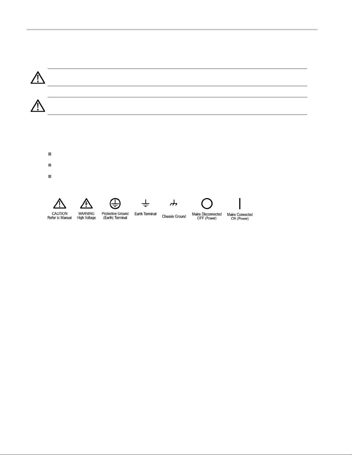
Symbols and Terms on the Product
These terms may appear on the product:
DANGER indicates an injury hazard immediately accessible as you read the marking.
WARNING indicates an injury hazard not immediately accessible as you r ead the marking.
CAUTION indicates a hazard to property including the product.
The following symbol(s) may appear on the product:
ummary
iv BitAlyzer Quick Start User Manual

Compliance Info
rmation
Compliance In
This product is intended for sale and use within the United States only.
This section lists safety and environmental standards with which the instrument complies.
Safety Compliance
U.S. Nationally Recognized Testing Laboratory Listing
UL 61010-1:2004, 2ndEdition. Standard for electrical measuring and test equipment.
Canadian Certification
CAN/CSA-C22.2 No. 61010-1:2004. Safety requirements for electrical equipment for measurement, control, and
ry use. Part 1.
laborato
Additional Compliances
IEC 61010-1: 2001. Safety requirements for electrical equipment for m easurement, control, and laboratory use.
Equipment Type
formation
Test and measuring equipment.
Safety Class
Class 1 – grounded product.
Pollution Degree Description
A measure of the contaminants that could occur in the environment around and within a product. Typically the internal
ironment inside a product is considered to be the same as the external. Products should be used only i n the environment
env
for which they are rated.
Pollution Degree 1. No pollution or only dry, nonconductive pollution occurs. Products in this category are generally
encapsulated, hermetically sealed, or located in clean rooms.
Pollution Degree 2. Normally only dry, nonconductive pollution occurs. Occasionally a temporary conductivity that is
used by condensation must be expected. This location is a typical office/home environment. Temporary condensation
ca
occurs only when the product is out of service.
Pollution Degree 3. Conductive pollution, or dry, nonconductive pollution that becomes conductive due to condensation.
These are sheltered locations where neither temperature nor humidity is controlled. The area is protected from direct
unshine, rain, or direct wind.
s
ollution Degree 4. Pollution that generates persistent conductivity through conductive dust, rain, or snow. Typical
P
outdoor locations.
BitAlyzer Quick Start User Manual v

Compliance Info
Pollution Degree
Pollution Degree 2 (as defined in IEC 61010-1). Note: Rated for indoor use only.
Installation (Overvoltage) Category Descriptions
Terminals on this product may have different installation (overvoltage) category designations. The installation categories are:
Measurement Category IV. For measurements performed at the source of low-voltage installation.
Measurement Category III. For m easurements performed in the building installation.
Measurement Category II. For measurements performed on circuits directly connected to the low-voltage installation.
Measurement Category I. For measurements performed on circuits not directly connected to MAINS.
rmation
Overvolta
Overvoltage Category II (as defined in IEC 61010-1)
ge Category
Environmental Considerations
Product End-of-Life Handling
Observe the following guidelines when recycling an instrument or component:
Equipment recycling. Production of this equipment required the extraction and use of natural resources. The equipment
may con
end of life. To avoid release of such substances into the environment and to reduce the use of natural resources, we
encourage you to recycle this product in an appropriate system that will ensure that most of the materials are reused
or rec
Mercury Notification. This product uses an LCD backlight lamp that contains mercury. Disposal may be regulated due
to environmental considerations. Please c ontact your local authorities or, within the U nited States, refer to the E-cycling
Central Web page (www.eiae.org) for disposal or recycling information.
tain substances that could be harmful to the environment or human health if improperly handled at the product’s
ycled appropriately.
vi BitAlyzer Quick Start User Manual

Preface
The Tektronix BitAlyzer Bit Error Ratio Analyzers support serial data interfaces from 100 MHz to 1.5 GHz (BA1500) and
1.6 GHz (BA1600).
The BitAlyzer Analyzer combines a test pattern generator and error detector with advanced physical layer tests in one system.
The Generator produces a controlled data stream. When a clock is provided (either the internal clock synthesized by the
BitAlyzer, or an external clock), data bits of a user-selected data type will be generated. The data pattern can be one of the
predefined pseudo-random bit sequences (PRBS) installed in the Generator memory, or a user-created pattern.
The Error Detector compares the incoming data with a copy of the o riginal. Every bit error is tracked with an accuracy 1,000
times deeper than a sampling oscilloscope. The location of errors can be correlated with the eye diagram, pattern sensitivity,
error free interval, block errors, and other analysis methods. The error detection data can be stored for later analysis.
Documentation
Product Documentation
For information about: See these resources:
Initial Setup This Quick S tart User Manual
Operation and Analysis Online Help installed on instrument
Remote Control Remote control command list (PDF on instrument hard drive)
Specifications Technical Specifications PDF on instrument hard drive
Operating System Restore A separate partition on the instrument hard drive contains an operating system restore file
Preface
BitAlyzer Quick Start User Manual vii

Preface
viii BitAlyzer Quick Start User Manual

Installation
The BitAlyzer Analyzer is carefully packaged for shipping to ensure against damage. Nonetheless, damage or loss may
occur, and so we recommend you verify the contents of the shipping container, inspect the unit mechanically, and perform
a quick operational test when you first receive your unit.
A clear indicator of potential damage is a damaged shipping container. Please inspect the exterior of the shipping
container(s) to assess any damage. If damage is apparent, we recommend you keep the shipping container and all materials
until the unit is checked out electronically and mechanically. If damage has occurred, we recommend you contact your
shipping agent and Tektronix as soon as possible to report the situation.
The items that were shipped to you include:
BitAlyzer Instrument
Power Cord
USB Keyboard
USB Mouse
OEM Windows XP®Certificate
Registration Card
Installation
Quick Start User Manual
If the shipping container contents are not complete, please notify Tektronix immediately. Other items may be shipped with
your unit depending on optional configurations.
Calibration
Annual factory c alibration is recommended for this equipment. Contact Technical Support to arrange for factory calibration.
enance and Cleaning
Maint
Contact Tektronix Service.
Operating Requirements
e the instrument on a cart or bench. The instrument should rest on its bottom.
Plac
erve the following clearance requirements and dimensions:
Obs
:0in(0cm)
Top
t and right side: 7.6 cm (3 in)
Lef
tom: 0 cm (0 in) standing on feet, flip stands down
Bot
ar: 7.6 cm (3 in)
Re
fore operating the instrument, verify that the ambient temperature is within the specified range: +5°C to +40°C (+41°F
Be
to +104°F).
BitAlyzer Quick Start User Manual 1

Installation
Preventing ESD
CAUTION. Adir
the following information.
Electrostatic discharge (ESD) is a concern when handling any electronic equipment. T he instrument is designed with
robust ESD protectio
may damage the instrument. To avoid damage to the instrument, use the following techniques to prevent electrostatic
discharge to the instrument:
Discharge the static voltage from your body by wearin g a grounded antistatic wrist strap while connecting and
disconnecting cabl
A cable that is left
cables before connecting them to the instrument or device under test by momentarily grounding the center conductor of
the cable, or by connecting a 50 Ω termination to one end, prior to attaching the cable to the instrument.
Connections
Connect Peripherals
The BitAlyzer An
Ifyouplantouse
TheLinePowerp
panel, as well as four USB 2.0 ports.
ect electrostatic discharge can damage the instrument input. Tolearn how to avoid this damage, read
n; however it is still possible that large d ischarges of static electricity directly into the signal input
es and adapters. The instrument provides a front panel connection for this purpose.
unconnected on a bench can develop a large static charge. Discharge the static voltage from all
alyzer supports both a mouse and a keyboard in addition to the touch screen.
a mouse and/or keyboard, connect them to any open USB port on the Analyzer before turning on the power.
lug and connectors for ground, network, monitor, Com1, and IEEE-488 (remote control) are on the rear
Clock and Data Con nectors
The BitAlyzer Generator uses either an internal clock or an optional external clock source. The Clock connectors are on the
front panel. 50 Ω SMA cables and connectors are recommended.
A ground connector is provided at the lower left of the front panel.
2 BitAlyzer Quick Start User Manual
 Loading...