

Page 1
TEK-DPG
Deskew Pulse Generator
Instructions
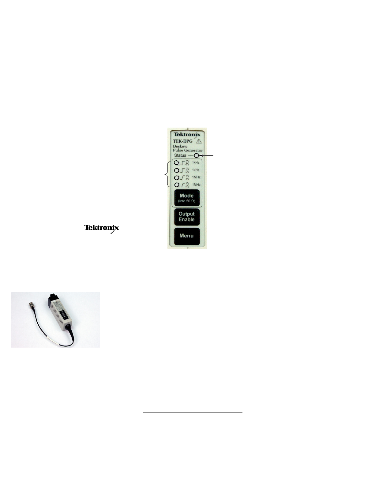
Controls and Indicators
The generator functions are described below.
Status LED
The Status LED glows amber at power-on to
indicate that the generator is on and the output at
the BNC cable is not enabled.
The Status LED glows green after the Output
Enable button is pressed once. Press the button
again to disable the output. (The LED glows
amber.)
The Status LED glows red to indicate an error
condition. If the Status LED glows red,
disconnect and reconnect the generator to clear
the fault that might have occurred.
Status LED
Mode LEDs
Equipment Required to Deskew Probes
The following equipment is required to deskew
your probes:
H Oscilloscope with the TekVPI interface
H TEK--DPG Deskew Pulse Generator
H Tektronix Power Measurement Deskew Fix-
ture, part number 067--1686--XX, with instructions
H Tektronix voltage or current probes to des-
kew
Deskew the Probes
Refer to the table and illustration on the back
page as you perform the following steps:
Connect the Generator
1. Plug the generator into any channel (1--4) of
the oscilloscope.
2. Connect the BNC cable from the generator to
either the Port A or Port B input of the
deskew fixture.
The input that you use depends on the type
of probes you have and the operation that
you want to perform. (Refer to the table on
the back of the page and on the deskew
fixture instructions.)
www.tektronix.com
*P071234100*
071-2341-00
Overview
The TEK-DPG Deskew Pulse Generator is a
signal-generating accessory for Tektronix
instruments that feature the TekVPI interface,
including DPO3000 Series and DPO/MSO4000
Series oscilloscopes.
The TEK-DPG generator provides a source
signal to the Power Measurement Deskew
Fixture (Tektronix part number 067-1686-XX),
used to deskew Tektronix probes.
The TEK-DPG generator is not required for, and
is not supported by DPO7000 Series
oscilloscopes. These models provide the
appropriate source signal at the Probe Calibration
output on the front-panel BNC connector.
The generator and deskew fixture allow you to
precisely deskew the time differences between
instrument channels of current and voltage
probes (necessary when you are using the probes
in power measurement applications).
Mode Button and LEDs
Press the Mode button to cycle through the
following output signals:
H Mode 1: 1 Vpk--pk @ 1 kHz
H Mode 2: 2 Vpk--pk @ 1 kHz
H Mode 3: 2 Vpk--pk @ 1 MHz
H Mode 4: 8 Vpk--pk @ 1 MHz
A green LED lights next to the selected mode.
Output Enable Button
Press the Output Enable button to pass the
generator signal out through the BNC cable, and
to enable the trigger signal on the oscilloscope
channel that the generator is plugged into.
The Status LED glows green to indicate that the
output at the BNC cable is enabled.
Menu Button
Press the Menu button to display the generator
function selections on the oscilloscope screen.
NOTE. Not all oscilloscope models support
the menu button.
Select the Signal
3. If you want to control the generator functions
from the oscilloscope screen, press the Menu
button on the generator.
NOTE. Not all oscilloscope models support
the menu button.
Y ou can perform steps 4 and 5 from the
oscilloscope screen or the generator buttons.
4. Press the Mode button to select the output
signal that is required for your probe and
oscilloscope combination.
5. Press the Enable button to apply the
generator signal to the deskew fixture.
6. Refer to the deskew fixture instructions to
complete the procedure.
Copyright E Tektronix, Inc. All rights reserved
Page 2
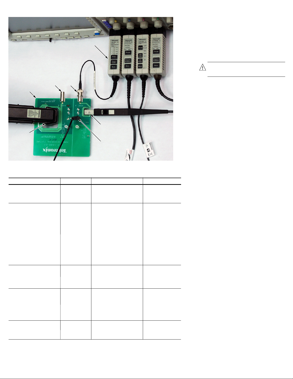
TEK-DPG
pulse generator
Deskew fixture
inputs
AB
Deskew
fixture
Small
current probe
Large
current
probe
Probe1(range) Operation Oscilloscope and Output mode Use input connector
Passive voltage probes, including:
P6139A
P5050
& other 10X passive probes
Active voltage probes, including:
TAP1500 (10X)
TAP2500 (10X)
TAP3500 (10X)
TDP0500 (5X, 50X)
TDP1000 (5X, 50X)
TDP1500 (1X, 10X)
P6243 (10X)
P6245 (10X)
P6246 (1X, 10X)
P6247 (1X, 10X)
P6248 (1X, 10X)
P6250 (5X, 50X)
P6251 (5X, 50X)
High voltage probes, including:
P5200 (50X, 500X)
P5205 (50X, 500X)
P5210 (100X, 1000X)
P6135A (Adj. to 10X)
Small current probes2, including:
TCP0030 (5A, 30A)
TCP202 (15A)
TCP312 (5A, 30A)
TCP305 (25A, 50A)
A6302 (20A)
A6312 (20A)
Large current probes2, including:
TCP0150 (25A, 150A)
TCP303 (25A, 150A)
A6303 (100A)
1
Not all probes are usable with all instruments, and some voltage probes may require a TPA-BNC Adapter.
2
Some current probes require an amplifier to operate and/or may need an adapter to connect to instruments that
feature the TekVPI interface.
Compensate timing
with respect to
current probes
Compensate timing
with respect to
current probes
Compensate timing
with respect to
current probes
Compensate timing
with respect to
voltage probes
Compensate timing
with respect to
voltage probes
Voltage probe
DPO3000: Mode 2
DPO/MSO4000: Mode 1
DPO3000: Mode 2
DPO/MSO4000: Mode 1
DPO3000: Mode 2/4
DPO/MSO4000: Mode 1/4
DPO3000: Mode 2/4
DPO/MSO4000: Mode 1/4
DPO3000: Mode 4
DPO/MSO4000: Mode 4
A or B, depending on
current probe type
A or B, depending on
current probe type
A or B, depending on
current probe type
A
B
Safety Summary
To avoid potential hazards, use this product only
as specified.
To avoid fire or personal injury, do not operate in
wet/damp conditions.
Keep product surfaces clean and dry.
Safety terms in this manual
WARNING. These statements identify
conditions or practices that could result in
personal injury or loss of life.
Warranty Information
For warranty information, go to
www.tektronix.com\service, and then use the
provided links to search for your product’s
warranty.
Contacting Tektronix
Tektronix, Inc.
14200 SW Karl Braun Drive
PO Box 500
Beaverton, OR 97077
USA
For product information, sales, service, and
technical support:
H In North America, call 1 --800--833-- 9200.
H Worldwide, visit www.tektronix.com to find
contacts in your area.
 Loading...