

Tektronix TekConnect User manual
TekConnect Interface
Calibration Adapter
Instructions
071-1016-00
www.tektronix.com
*P071101600*
071101600
WARRANTY SUMMARY
Tektronix warrants that the products that it
manufactures and sells will be free from defects in
materials and workmanship for a period of ninety
(90) days from the date of shipment from an
authorized Tektronix distributor. If a product or
CRT proves defective within the respective period,
Tektronix will provide repair or replacement as
described in the complete warranty statement.
To arrange for service or obtain a copy of the
complete warranty statement, please contact your
nearest Tektronix sales and service office.
EXCEPT AS PROVIDED IN THIS SUMMARY
OR THE APPLICABLE WARRANTY
STATEMENT, TEKTRONIX MAKES NO
WARRANTY OF ANY KIND, EXPRESS OR
IMPLIED, INCLUDING WITHOUT
LIMITATION THE IMPLIED WARRANTIES
OF MERCHANTABILITY AND FITNESS FOR
A PARTICULAR PURPOSE. IN NO EVENT
SHALL TEKTRONIX BE LIABLE FOR
INDIRECT, SPECIAL OR CONSEQUENTIAL
DAMAGES.
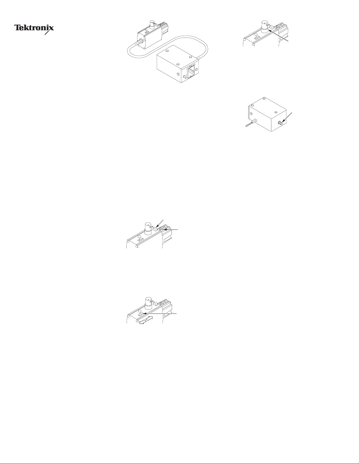
Figure 1: TekConnect Interface Calibration Adapter
The TekConnect Interface Calibration Adapter,
Tektronix part number 067-0422-00, may be
necessary to complete the performance
verification and adjustment procedures for your
TekConnect probe. Refer to your probe manual or
adjustment software for specific instructions on
using the adapter.
The adapter connects between the host instrument
and the probe under test and provides connectors
for probe signal and offset voltage measurements.
When the adapter is connected to the oscilloscope,
the adapter is identified as a valid calibration
device, and the Volts/div readout on the
oscilloscope displays ##. However, additional
power supplies necessary to power the probe are
not enabled until a TekConnect probe is connected
to the adapter and identified by the oscilloscope.
Adapter features
Latch button
Latch
Latch button. The spring-loaded latch mechanically
retains the adapter to the oscilloscope. To release
the adapter, grasp the adapter housing, press the
latch button, and pull the adapter straight out of
the oscilloscope.
Offset
VAR
GND
Offset output select switch.
selects between ground and the offset voltage level
from the oscilloscope.
Leave the switch in the ground position for the
performance verification procedures. The variable
position is only used in the adjustment procedures.
GND/Variable
The offset output switch
Offset voltage
output
Offset voltage. The offset voltage of the probe is
accessed through the BNC connector.
Measure the offset voltage using a DVM, BNC
coaxial cable, and BNC-to-dual-banana jack.
Signal out
Signal out.
box allows for direct monitoring of the probe
signal.
Installation
Unless specified otherwise, use this procedure to
install the calibration adapter.
1. Turn on the oscilloscope, and enable the
2. Connect the probe calibration adapter to the
3. Connect the probe to the probe calibration
4. Allow 30 minutes for the equipment to warm
5. Follow the procedures for the probe you are
6. Refer to the Tektronix website at
The SMA connector on the rear of the
channel you will be using.
oscilloscope. The Volts/div readout on the
oscilloscope displays ##.
adapter.
up.
testing or adjusting, using the corresponding
manual or software.
www.tektronix.com for more information on
calibrating your probe.
Copyright Tektronix, Inc.
 Loading...