

Page 1

Instructions
TDSXF13
RS-232/Centronics Upgrade Kit
070-9634-02
Warning
The servicing instructions are for use by qualified
personnel only. To avoid personal injury, do not
perform any servicing unless you are qualified to
do so. Refer to all safety summaries prior to
performing service.
Page 2

Copyright T ektronix, Inc. All rights reserved.
T ektronix products are covered by U.S. and foreign patents, issued and pending. Information in this publication supercedes
that in all previously published material. Specifications and price change privileges reserved.
Printed in the U.S.A.
T ektronix, Inc., P.O. Box 1000, Wilsonville, OR 97070–1000
TEKTRONIX and TEK are registered trademarks of T ektronix, Inc.
Page 3
Kit Description
The TDSXF13 kit includes parts and instructions for installing Option 13:
RS-232/Centronics Interface into the oscilloscopes listed under Instruments.
Instruments
TDS500A and later All serial numbers
TDS620A/B All serial numbers
TDS640A All serial numbers
TDS680B All serial numbers
Minimum Tools and Equipment List
Tool Part number
One screwdriver with a size T-20 Torx tip n/a
One screwdriver with a size T-15 Torx tip n/a
Torque driver capable of 16 inch-pounds
(1.81 newton-meters)
n/a
Kit Parts List
RS-232/Centronics Upgrade Kit
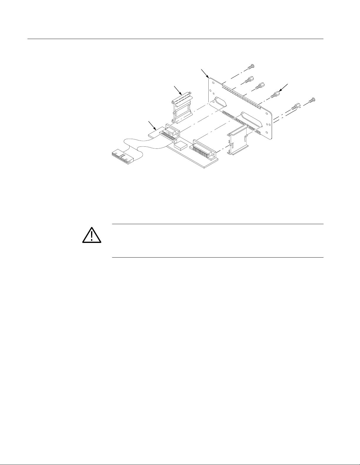
The following table and Figure 1 identify the parts list for this kit.
Qty Part number Name & description
1 ea 070-9634-xx Manual, tech instructions;TDSXF13
1 ea 070-8567-xx Manual tech: Option 13 RS-232/Centronics
1 ea 672-1397-00 Circuit board assy: ECB/Brkt Assy consisting of the
following: (see Figure 1):
1 ea 671-2437-00 Circuit board assy: RS-232/Centronics
2 ea 407-3825-00 Bracket, ckt bd: plastic, rear
1 ea 386-6182-00 Plate, rear: aluminum, RS-232/Centronics
4 ea 131-0890-01 Lock, connector: 4-40 X 0.312 L, hex hd, stl
2 ea 348-1300-00 Shield, gasket, clip on
1
Page 4
TDSXF13
Rear plate
Figure 1: RS-232/Centronics hardcopy interface replaceable parts
Service Safety Summary
WARNING. The servicing instructions are for use by qualified personnel only. To
avoid personal injury, do not perform any servicing unless you are qualified to
do so. Refer to the General Safety Summary in the appropriate TDS service
manual before performing any service.
RS-232/Centronics
circuit board
Bracket
Connector lock
Do Not Service Alone
Avoid Exposed Circuitry
Use Care When Servicing
With Power On
2
Do not perform internal service on this product unless another person capable of
rendering first aid and resuscitation is present.
To avoid injury, remove jewelry such as rings, watches, and other metallic
objects. Do not touch exposed connections and components when power is
present.
Dangerous voltages or currents may exist in this product. Disconnect the power,
remove the battery (if applicable), and disconnect the test leads before removing
protective panels, soldering, or replacing components.
RS-232/Centronics Upgrade Kit
Page 5

Installation Instructions
The instructions needed to upgrade the TDS follow. It is assumed service
personnel, somewhat familiar with the instrument, will install the upgrade. If
further details are required for disassembly or assembly, refer to the appropriate
TDS service manual. For assistance with installing this kit, please call your
nearest Tektronix Service Center.
CAUTION. To prevent static-discharge damage, service the instrument only in a
static-free environment. Observe standard handling precautions for static-sensitive devices while installing this kit. Always wear a grounded wrist and foot
strap while installing this kit.
Rear Cabinet and Cover Removal
Refer to Figure 2 while performing the following procedure:
1. Install the front cover. Set the oscilloscope face down with the front cover on
the work surface and the bottom facing up.
2. Unplug the power cord from its receptacle at the rear panel.
3. Remove the four screws securing the rear cover to the oscilloscope. Use the
screwdriver with a size T-20 Torx
4. Grasp the left and right edges of the cabinet at the rear. Pull upward to slide
the cabinet off the oscilloscope. Do not bind or snag the cabinet on the
internal cabling of the oscilloscope as you remove it.
tip. Lift off the rear cover.
RS-232/Centronics Upgrade Kit
3
Page 6

TDSXF13
T-20 screws (4)
Rear cover
Cabinet
Figure 2: Oscilloscope rear cover and cabinet removal
4
RS-232/Centronics Upgrade Kit
Page 7

Retainer Bracket Removal
Refer to Figure 3 while performing the following procedure:
1. Remove the two screws securing the retainer bracket assembly. Use the
2. Slide the retainer bracket assembly out and remove it from the rear chassis.
screwdriver with a size T-15 Torx
assembly of the new rear plate.
TDSXF13
tip. Set aside both screws for later
Retainer bracket
T-15 screws (2)
RS-232/Centronics Upgrade Kit
Figure 3: Retainer bracket removal
5
Page 8

TDSXF13
Circuit Board Assembly Installation
Refer to Figure 4 while performing the following procedure:
1. Slide the circuit board assembly into the rear chassis.
2. Connect the cable connector to the processor-display circuit board connector.
3. Replace the two screws securing the rear plate of the retainer bracket. Use
the screwdriver with a size T-15 Torx
Cable
connection
tip.
Rear plate
T-15 screws (2)
Circuit board
Figure 4: Circuit board assembly installation
6
RS-232/Centronics Upgrade Kit
Page 9

TDSXF13
Cabinet and Rear Cover
Replacement
Diagnostics
Install the cabinet and rear cover. Perform the reverse of the Rear Cabinet and
Cover Removal procedure beginning on page 3.
NOTE. When reinstalling the four screws at the rear panel, use the torque driver
to tighten the screws to 16 inch-lbs torque (1.81 newton-meters).
The oscilloscope has two levels of internal diagnostics: short confidence and
extended. The oscilloscope automatically executes the short set when powered
on. If the hardcopy feature fails the short diagnostic routine, use the following
procedure to execute the extended diagnostics.
Prerequisites: Power on the oscilloscope and allow a 20 minute warm-up before
doing this procedure:
1. Press SHIFT UTILITY
Execute (main) ➞ OK Confirm Run Test (side).
2. The internal diagnostics routine checks the oscilloscope functions, but does
not check the printer function. When finished, the oscilloscope displays an
on-screen report of any failed modules, features, or interfaces.
➞ System (main) ➞ Diag/Err (pop-up) ➞
3. If the hardcopy feature fails diagnostics, verify that all cables are securely
seated and have not been damaged.
4. If the hardcopy feature continues to fail diagnostics, order a replacement
RS-232/Centronics circuit board (see the Parts List on page 1). Then follow
the installation instructions beginning on page 3.
RS-232/Centronics Upgrade Kit
7
Page 10

TDSXF13
V erify Installation
The following procedure uses a RS-232 or Centronics compatible hardcopy
device to verify that you have correctly installed the TDSXF13 upgrade kit.
1. Connect the power cord from the rear-panel power connector to the power
system.
2. Connect your hard copy device to the RS-232 or Centronics interface on the
rear panel (as shown in Figure 5).
Many printers, such as the Tektronix HC220, use Centronics interfaces. Many
hardcopy devices, including the HC100 with option 03, provide RS-232 support.
Setup Communication
Parameters
Digitizing oscilloscope
RS-232 or Centronics cable
Figure 5: Connecting the digitizing oscilloscope directly to the hardcopy device
To set up the communication parameters for a printer attached directly to the
oscilloscope RS-232 or Centronics port, do the following:
Press SHIFT UTILITY
gure
(main) ➞ Hardcopy (Talk Only)(side).
Setting Hardcopy Parameters. To specify the hardcopy format, layout, and type of
port using the hardcopy menu do the following:
1. Press SHIFT HARDCOPY MENU to bring up the Hardcopy menu.
➞System(main) ➞ I/O (pop-up) ➞ Confi-
Hardcopy device
2. Select the format that is compatible with your hardcopy device.
3. Press SHIFT HARDCOPY MENU
channel to send your hardcopy through. The choices are GPIB, RS-232,
Centronics, and File. Choose RS-232 or Centronics.
4. Press HARDCOPY to print your hardcopy. Your hardcopy device should
now print a picture of the digitizing oscilloscope screen.
If you have problems, call the nearest Tektronix, Inc., field office for assistance.
8
➞Port (main) to specify the output
RS-232/Centronics Upgrade Kit
Page 11

g End of document g
TDSXF13
RS-232/Centronics Upgrade Kit
9
Page 12

 Loading...