

Page 1

Instructions
TDSXF05
TDS Series Digitizing Oscilloscopes
Video Trigger Upgrade Kit (Option 05)
070-9636-02
Warning
The servicing instructions are for use by qualified
personnel only. To avoid personal injury, do not
perform any servicing unless you are qualified to
do so. Refer to all safety summaries prior to
performing service.
Page 2

Copyright T ektronix, Inc., All rights reserved.
T ektronix products are covered by U.S. and foreign patents, issued and pending. Information in this publication supercedes
that in all previously published material. Specifications and price change privileges reserved.
Printed in the U.S.A.
T ektronix, Inc., P.O. Box 1000, Wilsonville, OR 97070–1000
TEKTRONIX and TEK are registered trademarks of T ektronix, Inc.
Page 3

Kit Description
This kit includes parts and instructions to upgrade a standard TDS Series
instrument with Option 05, Video Trigger.
The TDSXF05 Video Trigger kit gives you a variety of tools for investigating
events that occur when a video signal generates a horizontal or vertical sync
pulse. The tools allow you to investigate a range of NTSC, PAL, SECAM and
high definition TV signals. To make one of these kits work, you must have the
Video Trigger hardware (provided in the kit) installed in a TDS Series oscilloscope.
Instruments
TDS500A and later, all serial numbers
TDS600A and later, all serial numbers
TDS700A and later, all serial numbers
Minimum Tools and Equipment List
Tool Part number
Torxdriv driver & T-15, T -20 tip n/a
Torque driver n/a
3/16 inch nut driver n/a
Video Trigger Upgrade Kit (Option 05)
1
Page 4

Kit Description
Kit Parts List
Compt no. Quantity Part number Description
1 ea 01 1-0055-01 Term, coaxial:75 ,1 W, bnc (Video trigger accessory)
1 ea 013-0278-00
070-8762-xx
1 ea 070-8748-xx Manual tech: Instruction, TDS Option 05
1 ea 070-9636-xx Manual Tech: Instructions, TDSXF05, field kit
1 ea 174-0655-00 Cable assy, rf: Video trigger, 50 , coax, sma to petola, 22.4 length. 9-2
2 ea 174-2574-00 Ca assy , sp: Ribbon, 28 awg, 4.875 inches length
1 ea 174-3728-00 Ca assy , sp: Ribbon, 40-pin, 28 awg, 5.15 inches length
1 ea 174-3729-00 Ca assy , sp: Ribbon, 50-pin, 28 awg, 6.0 inches length
1 ea 174-3340-00 Ca assy , sp: Ribbon, 40-pin, 28 awg, 6.4 inches length
Video clamp: Display, back porch clamp (Video trigger accessory)
Manual tech: User,Video Clamp
(Cable for TDS 500A and TDS 600A series except the TDS 684A)
(Cable for the TDS 500B, TDS 600B, TDS 700A and later series and
TDS 684A)
(Cable for the TDS 500B, TDS 600B, TDS 700A and later series and
TDS 684A)
(Cable for the TDS 500A and TDS 600A series except the TDS 684A)
2 ea 214-2270-00 Contact, elec: Clip, attenuators to cabinet
2 ea 210-0409-00 Nut, plain, hex: 8-32 x 0.312 brass, cd plate
2 ea 21 1-0720-00 Screw, assembly, washer: 6-32 x 0.500, pnh, T-15
A27 1 ea 671-4095-00 Circuit board assy: Option connector
A29 1 ea 671-2476-04 Circuit board assy: TV trigger
A14 1 ea 671-2770-00 Circuit board assy: D1-BUS
(For TDS 500A and TDS 600A except TDS 684A)
A14 1 ea 671-2848-00 Circuit board assy: D1-BUS
(For TDS 500B, TDS 600B, TDS 700 and later series and the TDS 684A )
2
Video Trigger Upgrade Kit (Option 05)
Page 5

Service Safety Summary
WARNING. The servicing instructions are for use by qualified personnel only. To
avoid personal injury, do not perform any servicing unless you are qualified to
do so. Refer to the General Safety Summary in the appropriate TDS Series
service manual before performing any service.
Kit Description
Do Not Service Alone
Avoid Exposed Circuitry
Use Care When Servicing
With Power On
Do not perform internal service on this product unless another person capable of
rendering first aid and resuscitation is present.
To avoid injury, remove jewelry such as rings, watches, and other metallic
objects. Do not touch exposed connections and components when power is
present.
Dangerous voltages or currents may exist in this product. Disconnect the power,
remove the battery (if applicable), and disconnect test leads before removing
protective panels, soldering, or replacing components.
Video Trigger Upgrade Kit (Option 05)
3
Page 6

Installation Instructions
These instructions assume a certain familiarity with the instrument. If further
details are required for disassembly or assembly, refer to the appropriate
TDS Series service manual. For assistance to install this kit, please call your
nearest Tektronix, Inc., Service Center or Tektronix Inc., Factory Service.
CAUTION. To prevent static discharge damage, service the instrument only in a
static-free environment. Observe standard handling precautions for static-sensitive devices while installing this kit. Always wear a grounded wrist and foot
strap while installing this kit.
Rear Cover and Cabinet Removal
Equipment required One screwdriver with a size T-20 Torx tip.
1. Install the front cover. Set the oscilloscope face down with the front cover on
the work surface and the bottom facing up (see Figure 1).
2. Unplug the power cord from its receptacle at the rear panel.
3. Using the screwdriver with size T-20 Torx
securing the rear cover to the oscilloscope. Lift off the rear cover.
4. Grasp the left and right edges of the cabinet at the rear. Pull upward to slide
the cabinet off the oscilloscope. Do not bind or snag the cabinet on the
oscilloscope internal cabling of the oscilloscope as you remove it.
tip, remove the four screws
4
Video Trigger Upgrade Kit (Option 05)
Page 7

T-20 screws (4)
Rear cover
Cabinet
Installation Instructions
Figure 1: Rear cover and cabinet removal
Video Trigger Upgrade Kit (Option 05)
5
Page 8

Installation Instructions
TV T rigger Circuit Board Addition
Equipment required One screwdriver with a size T-15 Torx tip.
1. The A23 SerPar circuit board (RS-232 Centronics) assembly must be
removed to allow the TV Trigger circuit board to be installed onto the
mounting posts, then locked in place by the rear SerPar circuit board
brackets. See Figures 2 and 6.
a. Using a screwdriver with size T-15 Torx
tip, remove the two screws
securing the rear plate of the A23 SerPar circuit board assembly.
b. Disconnect P37, the SerPar 26 pin ribbon cable connector, from J37 on
the Processor circuit board A11. Pull the cable and SerPar circuit board
assembly out of the instrument.
SerPar circuit board brackets (2)
SerPar cable connector P37
SerPar circuit board assembly
(Centronics RS-232)
T-15 screws (2)
Figure 2: Pull out A23 SerPar circuit board assembly
6
Video Trigger Upgrade Kit (Option 05)
Page 9
50 Coaxial cable
assembly, T ektronix part
number 174-0655-xx
Installation Instructions
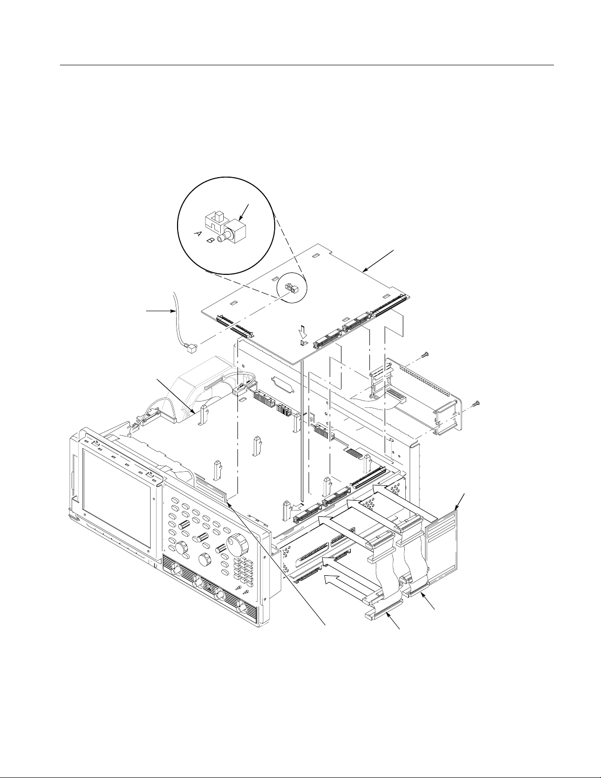
2. Install the TV Trigger circuit board A29 (provided in this kit) into the
instrument. Push down and slide the TV Trigger circuit board onto the board
mounts (see Figure 3). Refer to the Removal and Installation Procedures in
the TDS Series service manual for more detailed installation procedures.
J6
TV Trigger circuit board
J1
Processor circuit board
Option connector
circuit board
D1-BUS
Circuit board
Ribbon cable
Ribbon cable
Figure 3: Circuit board insertion
Video Trigger Upgrade Kit (Option 05)
7
Page 10

Installation Instructions
3. Connect the appropriate power ribbon cables (provided in this kit). The two
(2) ribbon cables interconnect to the analog power and digital power to the
Acquisition circuit board, Processor circuit board, and TV Trigger circuit
board.
4. Install the appropriate A14 D1-BUS board (provided in this kit).
NOTE. When plugging in the D1-BUS boards (see figure 3) make sure that they
remain plugged in on both ends after the kit is installed.
5. Install the Option Connector circuit board A27 (provided in this kit).
Carefully connect the bottom of the Option Connector circuit board to J39
on the Processor circuit board. Then connect the top of the Option Connector
to J1 on the TV Trigger circuit board.
6. Plug the sma connector of the 50 coaxial video cable (provided in this kit)
to J6 on the TV Trigger circuit board A29. Connect the petola end of the
cable to J1500 on the Acquisition circuit board. See Figure 4 for the
appropriate video cable routing.
7. Set the slide switch located on the TV Trigger circuit board to the following
position (see Figure 3):
a. Position A (BTL trigger IC) TDS 500B, TDS 684A, TDS 600B, and
TDS 700A and later instruments.
b. Position B (CTL trigger IC) TDS 500A and TDS 600A, except the
TDS 684A.
8
Video Trigger Upgrade Kit (Option 05)
Page 11

Installation Instructions
Route video cable
underneath the processor
circuit board.
Top view
Bottom view
TDS520A
TDS524A
J6
J1500
Route video cable
underneath the processor
circuit board.
Top view
Bottom view
TDS540A
TDS544A
J6
J1500
Top view
Bottom view
TDS620A
TDS640A
J6
TDS644A
TDS500B
TDS600B
TDS684A
TDS700A
and later
J1500
Top view
Bottom view
J6
J1500
Figure 4: Video cable routing (Acquisition to Processor)
Video Trigger Upgrade Kit (Option 05)
9
Page 12

Installation Instructions
Attenuator Electrical Contacts Installation
Equipment required One screwdriver with a size T-15 Torx tip.
TDS 500A and TDS 600A instruments (except TDS 684A) require electrical
contacts to be installed on the Attenuator circuit board.
NOTE. Examine the attenuator section located towards the front panel on the
bottom side of the oscilloscope. If the attenuators are located on a separate
circuit board assembly, perform the following procedure (see Figure 5).
1. Remove and discard the second and fourth screw and washer assemblies
from the Attenuator Circuit board using a T-15 Torxdriver. The screws and
washer assemblies are located nearest to the Acquisition circuit board.
2. Using the 8-32 nuts (provided in this kit) as spacers, place the nuts on
mounting holes just vacated by the T-15 screws just removed. The 8-32 nuts
are used as spacers.
CAUTION. To ensure proper operation of the new video trigger upgrade the
electrical contact clip must be in contact with the the cabinet when reassembled.
Make sure the electrical contact clip is position correctly. The small tab near the
mounting clip hole should be facing up and towards the Acquisition circuit
board.
3. Place the electrical contacts, clips (provided in this kit) on top of the nuts.
Secure the clips to the Attenuator circuit board by using the 6-32 x
0.500 inch panhead T-15 screws (provided in this kit).
10
Video Trigger Upgrade Kit (Option 05)
Page 13

T-15 6-32 0.500 (2)
Electrical contact clips (2)
8-32 Nuts (2)
Electrical contact
Installation Instructions
clip assembly
Figure 5: Partial view, attenuator electrical contacts installation
Video Trigger Upgrade Kit (Option 05)
11
Page 14

Installation Instructions
Replace A23 Circuit Board
Equipment required One torque driver
NOTE. When reinstalling the four screws at the rear panel, use the torque driver
to tighten the screws to 8 inch-lbs torque.
1. Do in reverse order, steps a to b of the TV Trigger Circuit board Addition
2. Make sure the A23 SerPar circuit board brackets slide over the TV Trigger
SerPar circuit board
procedure starting on page 6.
circuit board. This will lock the TV Trigger circuit board A29 into place. See
Figure 6.
bracket
Video Trigger board
12
Figure 6: TV Trigger and SerPar circuit board detail
Video Trigger Upgrade Kit (Option 05)
Page 15

Replace Cabinet and Rear Cover
Equipment required One screwdriver with a size T-20 Torx tip.
1. Do step 1 of the Rear Cover and Cabinet Removal procedure on
page 4.
2. Do in reverse order steps 2 through 4 of the Rear Cover and Cabinet
Removal procedure starting on page 4.
NOTE. When reinstalling the four screws at the rear panel, use the torque driver
to tighten the screws to 16 inch-lbs torque.
Installation Instructions
One torque driver.
Execute Diagnostics
Executing Extended
Diagnostics Routine
To ensure the Video Trigger is working correctly, perform the Diagnostics
procedure.
Prerequisites: Power on the oscilloscope and allow a 20 minute warm-up before
doing this procedure.
1. Press SHIFT UTILITY
Execute (main) ➞ OK Confirm Run Test (side).
2. The internal diagnostics routine checks oscilloscope functions. When
finished, the oscilloscope displays an on-screen report of any failed modules,
features, or interfaces.
3. If the video trigger feature fails diagnostics, verify that all cables are securely
seated and are not damaged.
4. If the video trigger feature continues to fail diagnostics, call the nearest
Tektronix, Inc., field office for assistance.
g End of document g
➞ System (main) ➞ Diag/Err (pop-up) ➞
Video Trigger Upgrade Kit (Option 05)
13
Page 16

Installation Instructions
14
Video Trigger Upgrade Kit (Option 05)
Page 17

Page 18

 Loading...