

Tektronix TDSPWR3 User manual

Printed Help Document
TDSPWR3
Power Measurement and Analysis Software
Adapted from the TDSPWR3 Power Measurement and Analysis Online Help
PHP0249, Version 1.00, 2003

Copyright © Tektronix, 2003, Inc. All rights reserved. Licensed software products are owned by Tektronix or its suppliers
and are protected by United States copyright laws and international treaty provisions.
Use, duplication, or disclosure by the Government is subject to restrictions as set forth in subparagraph (c)(1)(ii) of the Rights
in T echnical Data and Computer Software clause at DFARS 252.227-7013, or subparagraphs (c)(1) and (2) of the
Commercial Computer Software – Restricted Rights clause at FAR 52.227-19, as applicable.
Tektronix products are covered by U.S. and foreign patents, issued and pending. Information in this documentation
supercedes that in all previously published material. Specifications and price change privileges reserved.
Tektronix, Inc., P.O. Box 500, Beaverton, OR 97077
TEKTRONIX, TEK and TEKPROBE are registered trademarks of Tektronix, Inc.
TDSPWR3 PHP0249, Version 1.00, 2003.

Table Of Contents
GENERAL SAFETY SUMMARY ............................................................................................................. 1
To avoid Fire and Personal Injury ......................................................................................................................... 1
Terms in this Manual ............................................................................................................................................. 1
Terms in the Application ....................................................................................................................................... 1
INTRODUCTION ...................................................................................................................................... 3
Welcome.................................................................................................................................................................... 3
Online Help and Related documentation............................................................................................................... 4
Using Online Help.................................................................................................................................................... 4
Printing from Online Help ...................................................................................................................................... 5
Related documentation............................................................................................................................................5
Conventions .............................................................................................................................................................. 6
Contacting Tektronix .............................................................................................................................................. 7
Feedback ................................................................................................................................................................... 7
GETTING STARTED................................................................................................................................ 9
Introduction and Product Description...................................................................................................................9
Compatibility.......................................................................................................................................................... 10
Requirements and Restrictions............................................................................................................................. 11
Accessories.............................................................................................................................................................. 11
Current Probes....................................................................................................................................................... 12
Differential Probes................................................................................................................................................. 12
Updates through the website................................................................................................................................. 13
Installation procedures.......................................................................................................................................... 13
Installing the application...................................................................................................................................... 13
TDSPWR3 Software Analysis Printed Help Document i

Table of Contents
UTILITIES .............................................................................................................................................. 15
Deskewing Probes and Channels .......................................................................................................................... 15
Static Deskew....................................................................................................................................................... 15
Deskewing in TDS5000 series Oscilloscope with an Internal source.................................................................. 18
Deskewing in TDS7000, TDS6000 and CSA7000 series Oscilloscopes with an Internal source ....................... 20
Deskewing in TDS5000, TDS6000, TDS7000 and CSA7000 series Oscilloscopes with an External source..... 23
Deskewing using a Power Deskew Fixture.......................................................................................................... 26
SOA Overlay........................................................................................................................................................... 27
OPERATING BASICS ........................................................................................................................... 31
Application Interface ............................................................................................................................................. 31
Application Interface Menu Controls ..................................................................................................................31
Basic Application Functions.................................................................................................................................. 32
Using Online Help .................................................................................................................................................. 32
Minimizing and Maximizing the Application Window ......................................................................................32
Application Directories and File Names ..............................................................................................................32
File Name Extensions.............................................................................................................................................33
Returning to the Application.................................................................................................................................34
Exiting the Application.......................................................................................................................................... 34
Setting up TDSPWR3 to take Measurements .....................................................................................................34
Setting Up the Software......................................................................................................................................... 34
Table of Options-Common Configurations .........................................................................................................35
Table of Measurements and Configurations-Power Device Analysis................................................................36
Table of Measurements and Configurations-Line Power Analysis ................................................................... 40
Table of Measurements and Configurations-Output Analysis ..........................................................................42
Table of Measurements and Configurations-Modulation Analysis................................................................... 44
Table of Measurements and Configurations-Analysis Tools .............................................................................45
Taking a New Measurement .................................................................................................................................46
ii TDSPWR3 Software Analysis Printed Help Document

Table of Contents
About Taking Measurements................................................................................................................................ 46
Acquiring Data..................................................................................................................................................... 46
Analyzing the Results ............................................................................................................................................47
Selecting a Measurement....................................................................................................................................... 47
Common Configuration Panel .............................................................................................................................. 48
Math Setup ............................................................................................................................................................. 50
Hysteresis................................................................................................................................................................ 52
SOA Mask Editor................................................................................................................................................... 52
Power Device Analysis - Power Dissipation......................................................................................................... 54
Selecting and Configuring Measurements-Power Dissipation ............................................................................54
Viewing Results-Power Dissipation .................................................................................................................... 63
Generating Reports-Power Dissipation................................................................................................................ 65
Troubleshooting Switching Loss Results............................................................................................................. 66
B-H Analysis........................................................................................................................................................... 68
Selecting and Configuring Measurements-B-H Analysis.................................................................................... 68
Configuring Measurements.................................................................................................................................. 69
Viewing Results-B-H Analysis............................................................................................................................ 76
Generating Reports-B-H Analysis ....................................................................................................................... 82
Total Loss................................................................................................................................................................ 82
Selecting and Configuring Measurements-Total Loss......................................................................................... 82
Configuring Measurements.................................................................................................................................. 83
Viewing Results-Total Loss................................................................................................................................. 86
Generating Reports-Total Loss ............................................................................................................................ 88
Safe Operating Area .............................................................................................................................................. 88
Selecting and Configuring Measurements-Safe Operating Area ......................................................................... 88
Viewing Results-Safe Operating Area................................................................................................................. 90
SOA Overlay........................................................................................................................................................ 95
Utilities> SOA Overlay ....................................................................................................................................... 95
Generating Reports-Safe Operating Area ............................................................................................................ 97
Dynamic Resistance ............................................................................................................................................... 97
Selecting and Configuring Measurements-Dynamic Resistance ......................................................................... 97
Viewing Results-Dynamic Resistance................................................................................................................. 99
Generating Reports-Dynamic Resistance .......................................................................................................... 100
di/dt .......................................................................................................................................................................100
Selecting and Configuring Measurements-di/dt ................................................................................................ 100
Viewing Results-di/dt ........................................................................................................................................ 102
Generating Reports-di/dt.................................................................................................................................... 103
TDSPWR3 Software Analysis Printed Help Document iii

Table of Contents
dv/dt....................................................................................................................................................................... 104
Selecting and Configuring Measurements-dv/dt................................................................................................ 104
Viewing Results-dv/dt........................................................................................................................................105
Generating Reports-dv/dt................................................................................................................................... 106
Line Power Analysis-Power Quality................................................................................................................... 107
Selecting and Configuring Measurements-Power Quality.................................................................................107
Viewing Results-Power Quality......................................................................................................................... 108
Generating Reports-Power Quality ....................................................................................................................109
Current Harmonics..............................................................................................................................................110
Selecting and Configuring Measurements-Current Harmonics ......................................................................... 110
Configuring the Measurement............................................................................................................................110
Viewing Results-Current Harmonics ................................................................................................................. 115
Generating Reports-Current Harmonics ............................................................................................................119
Total Power Quality.............................................................................................................................................120
Selecting and Configuring Measurements-Total Power Quality .......................................................................120
Viewing Results-Total Power Quality ............................................................................................................... 124
Generating Reports-Total Power Quality........................................................................................................... 127
Output Analysis-Ripple Line ..............................................................................................................................127
Selecting and Configuring Measurements-Ripple Line ..................................................................................... 127
Viewing Results-Ripple Line............................................................................................................................. 128
Generating Reports-Ripple Line ........................................................................................................................ 129
Ripple Switching ..................................................................................................................................................130
Selecting and Configuring Measurements-Ripple Switching ............................................................................ 130
Viewing Results-Ripple Switching .................................................................................................................... 131
Generating Reports-Ripple Switching ...............................................................................................................131
Turn-On Time ...................................................................................................................................................... 132
Selecting and Configuring Measurements-Turn-On Time.................................................................................132
Viewing Results-Turn-On Time ........................................................................................................................133
Generating Reports-Turn-On Time....................................................................................................................134
Modulation Analysis-Pulse Width ......................................................................................................................135
Selecting and Configuring Measurements-Pulse Width ....................................................................................135
Viewing Results-Pulse Width ............................................................................................................................ 136
Generating Reports-Pulse Width........................................................................................................................137
Duty Cycle............................................................................................................................................................. 138
Selecting and Configuring Measurements-Duty Cycle...................................................................................... 138
Viewing Results-Duty Cycle..............................................................................................................................139
Generating Reports-Duty Cycle......................................................................................................................... 140
Clock Period .........................................................................................................................................................140
Selecting and Configuring Measurements-Clock Period ................................................................................... 140
Viewing Results-Clock Period........................................................................................................................... 141
Generating Reports-Clock Period ...................................................................................................................... 142
iv TDSPWR3 Software Analysis Printed Help Document

Table of Contents
Frequency Modulation ........................................................................................................................................ 142
Selecting and Configuring Measurements-Frequency....................................................................................... 142
Viewing Results-Frequency............................................................................................................................... 144
Generating Reports-Frequency .......................................................................................................................... 144
Analysis Tools-Spectral Analysis........................................................................................................................ 145
Selecting and Configuring Measurement........................................................................................................... 145
Viewing Results................................................................................................................................................. 147
Generating Reports ............................................................................................................................................ 148
Troubleshooting Spectral Analysis Error Messages .......................................................................................... 149
Saving and Recalling Setups ............................................................................................................................... 149
Saving a Setup ................................................................................................................................................... 149
Recalling a Saved Setup..................................................................................................................................... 149
Recalling the Default Setup ............................................................................................................................... 150
Recently Recalled Setup .................................................................................................................................... 150
Recently Saved Setup ........................................................................................................................................ 150
TUTORIAL ...........................................................................................................................................151
Introduction to the Tutorial................................................................................................................................ 151
Starting the Application ...................................................................................................................................... 151
Setting Up the Oscilloscope ................................................................................................................................. 151
Measuring Power Dissipation ............................................................................................................................. 151
Measuring B-H Analysis ..................................................................................................................................... 154
Stopping the Tutorial........................................................................................................................................... 157
Returning to the Tutorial .................................................................................................................................... 157
APPLICATION EXAMPLES ................................................................................................................159
About Application Examples .............................................................................................................................. 159
To Increase Efficiency in a Switching Power Supply .......................................................................................159
Measure Switching Loss.................................................................................................................................... 159
Analyze Switching Loss .................................................................................................................................... 161
Measure Magnetic Loss ..................................................................................................................................... 163
GPIB COMMANDS .............................................................................................................................. 165
About the GPIB Program ................................................................................................................................... 165
GPIB Reference Materials .................................................................................................................................. 165
TDSPWR3 Software Analysis Printed Help Document v

Table of Contents
Guidelines to GPIB Programming .....................................................................................................................165
Introduction to GPIB Commands ......................................................................................................................166
Starting and Setting Up the Application Using GPIB ......................................................................................166
Sample Program................................................................................................................................................... 167
Variable: TDS Command.................................................................................................................................... 178
Variable:Value TDS Command Arguments and Queries-Application, Sequencer ....................................... 179
Variable:Value TDS Command Arguments and Queries-Save, Recall .......................................................... 179
Variable:Value TDS Command Arguments and Queries-Measurement .......................................................180
Variable:Value TDS Command Arguments and Queries-Common Configuration...................................... 180
Variable:Value TDS Command Arguments and Queries-B-H Analysis ........................................................181
Variable:Value TDS Command Arguments and Queries-BH Analysis-Inductance ..................................... 181
Variable:Value TDS Command Arguments and Queries-Magnetic Loss ......................................................181
Variable:Value TDS Command Arguments and Queries-Magnetic property............................................... 182
Variable:Value TDS Command Arguments and Queries-Current Harmonics............................................. 184
Variable:Value TDS Command Arguments and Queries-Current Harmonics-IEC Standard.................... 184
Variable:Value TDS Command Arguments and Queries-Current Harmonics-AMD14 .............................. 185
Variable:Value TDS Command Arguments and Queries-Current Harmonics-MIL.................................... 185
Variable:Value TDS Command Arguments and Queries-Power Dissipation................................................ 185
Variable:Value TDS Command Arguments and Queries-Power Dissipation-Switching Loss..................... 186
Variable:Value TDS Command Arguments and Queries-Ripple Line........................................................... 188
Variable:Value TDS Command Arguments and Queries-Ripple Switching.................................................. 188
Variable:Value TDS Command Arguments and Queries-Total Power Quality............................................ 189
Variable:Value TDS Command Arguments and Queries-SOA.......................................................................190
Variable:Value TDS Command Arguments and Queries-Power Quality ......................................................191
Variable:Value TDS Command Arguments and Queries-Spectral Analysis ................................................. 191
Variable:Value TDS Command Arguments and Queries- Pulse Width Modulation.................................... 192
vi TDSPWR3 Software Analysis Printed Help Document

Table of Contents
Variable:Value TDS Command Arguments and Queries- Duty Cycle Modulation...................................... 193
Variable:Value TDS Command Arguments and Queries- Clock Period Modulation ..................................193
Variable:Value TDS Command Arguments and Queries- Frequency Modulation ...................................... 194
Variable:Value TDS Command Arguments and Queries-Error Codes ......................................................... 195
REFERENCE ....................................................................................................................................... 197
Short Cut Keys for TDSPWR3........................................................................................................................... 197
Error Codes for TDSPWR3................................................................................................................................ 198
Error Codes for TDSPWR3 Cont... ................................................................................................................... 200
Error Codes for TDSPWR3 Cont... ................................................................................................................... 201
Error Codes for TDSPWR3 Cont... ................................................................................................................... 205
Error Codes for TDSPWR3 Cont... ................................................................................................................... 207
Error Codes for TDSPWR3 Cont... ................................................................................................................... 208
Configuration Parameter Specifications............................................................................................................ 209
Parameters............................................................................................................................................................ 213
About Application Parameters........................................................................................................................... 213
File Menu........................................................................................................................................................... 213
Save/Recall Menu Parameters ...........................................................................................................................213
Preferences Parameters ...................................................................................................................................... 213
Measurement Menus.......................................................................................................................................... 214
Measurement Menu Parameters......................................................................................................................... 214
Control Panel Parameters................................................................................................................................... 214
Common Configuration Parameters .................................................................................................................. 215
Configure Power Dissipation Parameters .......................................................................................................... 216
Configure B-H Analysis Parameters.................................................................................................................. 217
Configure Total Loss Parameters....................................................................................................................... 218
Configure SOA Parameters................................................................................................................................ 219
Configure Dynamic Resistance Parameters....................................................................................................... 219
SOA Mask.......................................................................................................................................................... 219
Configure di/dt Parameters ................................................................................................................................ 219
Configure dv/dt Parameters ............................................................................................................................... 220
Configure Power Quality Parameters ................................................................................................................ 220
Configure Current Harmonics Parameters......................................................................................................... 220
Configure Total Power Quality Parameters ....................................................................................................... 221
Configure Ripple Line Parameters..................................................................................................................... 221
Configure Ripple Switching Parameters............................................................................................................ 222
Configure Turn-On Time Parameters ................................................................................................................ 222
Configure Pulse Width Modulation Parameters ................................................................................................222
TDSPWR3 Software Analysis Printed Help Document vii

Table of Contents
Configure Clock Period Modulation Parameters ............................................................................................... 223
Configure Duty Cycle Modulation Parameters.................................................................................................. 223
Configure Frequency Modulation Parameters ...................................................................................................223
Configure Spectral Analysis ..............................................................................................................................224
Results Menu......................................................................................................................................................224
Utilities Menu ....................................................................................................................................................224
Deskew-Static Deskew ......................................................................................................................................224
Real Time Deskew .............................................................................................................................................225
Report Menu ......................................................................................................................................................225
Help Menu..........................................................................................................................................................225
Measurement Algorithms.................................................................................................................................... 225
About Measurement Algorithms........................................................................................................................ 225
Oscilloscope Setup Guidelines........................................................................................................................... 225
Power Dissipation .............................................................................................................................................. 226
B-H Analysis......................................................................................................................................................230
Total Loss........................................................................................................................................................... 232
Safe Operating Area........................................................................................................................................... 232
Dynamic Resistance........................................................................................................................................... 234
di/dt .................................................................................................................................................................... 234
dv/dt ...................................................................................................................................................................235
Power Quality ....................................................................................................................................................235
Current Harmonics............................................................................................................................................. 238
Total Power Quality ...........................................................................................................................................239
Ripple Line and Ripple Switching .....................................................................................................................239
Turn-On Time .................................................................................................................................................... 240
Modulation Analysis ..........................................................................................................................................240
Clock Period and Frequency Modulation ..........................................................................................................240
Spectral Analysis................................................................................................................................................242
APPENDIX........................................................................................................................................... 245
Appendix A ...........................................................................................................................................................245
For P5205 probe................................................................................................................................................. 245
For TCP202 probe.............................................................................................................................................. 245
Appendix B ...........................................................................................................................................................246
GLOSSARY ......................................................................................................................................... 247
INDEX .................................................................................................................................................. 253
viii TDSPWR3 Software Analysis Printed Help Document

General Safety Summary
General Safety Summary
Review the following safety precautions to avoid injury and prevent damage to
the measurement instrument or any products connected to it. To avoid potential
hazards, use the software and measurement instrument only as specified.
While using this software, you may need to access other parts of the system.
Read the General Safety Summary and specification sections in other equipment
manuals for warnings, cautions, and ratings related to operating the system with
this software.
To avoid Fire and Personal Injury
Connect and Disconnect Properly. Connect the probe output to the
measurement instrument before connecting the probe to the circuit under test.
Disconnect the probe input and the probe ground from the circuit under test
before disconnecting the probe from the measurement instrument.
Observe All Terminal Ratings. To avoid fire or shock hazard, observe all
ratings and markings on the measurement instrument and other equipment used
with this software. Consult the individual product manuals for further ratings
information before making connections to the circuit under test.
Do Not Operate With Suspected Failures. If you suspect there is damage to the
measurement instrument or other equipment being used with this software, have
it inspected by qualified service personnel.
Terms in this Manual
These terms may appear in this manual:
WARNING. Warning statements identify conditions or practices that could
result in injury or loss of life.
CAUTION. Caution statements identify conditions or practices that could result
in damage to the measurement instrument or other property.
Terms in the Application
The application displays a caution dialog box warning you to use only
appropriately rated voltage and current probes when launched from the
oscilloscope menu. Press OK to start the application. If you do not select Ok, the
application waits for ten seconds and automatically displays the default screen.
TDSPWR3 Software Analysis Printed Help Document 1

General Safety Summary
2 TDSPWR3 Software Analysis Printed Help Document
Introduction
Welcome
TDSPWR3 is a power measurement and analysis software that runs on TDS5000,
TDS6000, TDS7000 and CSA7000 series oscilloscopes. TDSPWR3 allows you
to acquire, measure and analyze various switching power supply signals at
different test points. The application provides a simple and direct means of
obtaining results about Switching devices, Magnetic components and
Precompliance tests to EN 61000-3-2 Std for the Switch Mode Power Supply.
The features of TDSPWR3 are:
Introduction
Power Device Analysis analyzes the switching devices in the power supply
such as FET (Field Effect Transistor), BJT (Bi Polar Junction Transistor)
and IGBT (Integrated Gated Bi Junction Transistor). The measurements
include Power Dissipation, B- H Analysis, Total loss, Safe Operating Area
(SOA), SOA Mask test, Dynamic Resistance, di/dt and dv/dt.
Line Power Analysis measures Power Quality, Current Harmonics and
Total Power Quality.
Output Analysis measures Ripple Line, Ripple Switching and Turn-On
Time.
Modulation Analysis is trend plot of Pulse Width Modulation, Clock
Period Modulation, Duty Cycle Modulation and Frequency Modulation with
cursor gated measurements.
Spectral Analysis analyses the frequency component that contributes to the
electromagnetic interference and measures the noise/ripple at the DC output
voltage.
A Report Generator tool helps you create and print custom reports.
Deskew and SOA Overlay utilities.
TDSPWR3 Software Analysis Printed Help Document 3

Introduction
To return to the Table of Contents, select Help Topics from the Help
Topic menu.
Online Help and Related documentation
You can access the information on how to operate the application along with the
oscilloscope through the following related documents and online help.
Using Online Help
Select Help on the right side of the application menu bar to bring up the help file.
Tables of Contents (TOC) tab —- organizes the Help into book-like sections.
Select a book icon to open a section; select any of the topics listed under the
book.
Index tab —- enables you to scroll a list of alphabetical keywords. Select the
topic of interest to bring up the appropriate help page.
Find tab —- allows a text-based search. Follow these steps:
1. Type the word or phrase you want to find in the search box.
2. Select some matching words in the next box to narrow your search.
3. Choose a topic in the lower box, and then select the Display button.
To print a topic, select the Print button from the Help Topics menu bar.
Select Options from the menu bar for other commands, such as to annotate a
topic, keep the help window on top, or to use system colors.
Select the Back button to return to the previous help window. Use the Hyperlink
to jump from one topic to another. If the Back button is grayed out or a jump is
not available, choose the Help Topics button to return to the originating help
folder.
Browse buttons (Next >> and Previous <<) allow you to move forward and
backward through topics in the order of the Table of Contents (TOC).
Sometimes you will see the word, Note, in the topic text. This indicates
important information.
Note:
TDSPWR3 Software Analysis Printed Help Document 4
Introduction
Certain aspects of the online help are unique to applications that run on the
oscilloscope.
Green text (with no underlines) indicates a pop-up. Select the green text to
display a pop-up for a brief help message. Select the help message to return to the
topic.
Green-underlined text indicates a jump (hyperlink) to another topic. Select the
green text to jump to the related topic. For example, select the green text to jump
to the topic on Online Help and Related Documentation and the Back button to
return to the topic’s page.
You can tell when the cursor is over an active hyperlink (button, jump, or
pop-up), because the cursor arrow changes to a small hand.
Note: the light bulb and word Tip in the graphic
additional information to help you function more efficiently.
Printing from Online Help
Some online help topics have color in the examples of the displayed application.
If you want to print this type of topic on a monochrome printer, some
information may not print because of certain colors. Instead, you should print the
topic from the PDF (portable document format) file that corresponds to the
Online Help. You can find the file in the Documents directory on the Optional
Applications Software on Windows-Based Oscilloscopes CD-ROM. The figures
of application menus in the PDF file are gray scale so the relevant information
will appear on the printed page.
Related documentation
In addition to the Online Help, you can access other information on how to
operate the oscilloscope through the following related documents:
Oscilloscope Information: The user manual and user online help for your
oscilloscope provides general information on how to operate the
oscilloscope.
This graphic indicates
You can download PDF versions of many user manuals from the Tektronix
Website.
Programmer Information: The online programmer guide for your
oscilloscope provides details on how to use GPIB commands to control the
oscilloscope.
You can download programmer information and examples from the
Tektronix Website.
TDSPWR3 Software Analysis Printed Help Document 5

Introduction
Refer to the Optional Applications Software on Windows-Based Oscilloscopes
Installation Manual for the following information:
Software warranty
Software license agreement
List of all available applications, compatible oscilloscopes, and relevant
software and firmware version numbers
How to apply a new label
Installation procedures
How to enable an application
How to download updates from the Tektronix Website
You can find a PDF (portable document format) file for this document in the
Documents directory on the Optional Applications Software on Windows-Based
Oscilloscopes CD-ROM. The CD booklet only contains information on installing
the application from the CD and on how to apply a new label.
Conventions
Online help uses the following conventions:
Refers to the TDSPWR3 Power Measurements solution as TDSPWR3
Application or as the Application or as Power Measurements 3.
Refers to the configuration panel on the left side of the application as the
Common Configuration Panel or Configuration Panel. This is common to
many measurements.
When steps require a sequence of selections using the application interface,
the ">" delimiter marks each transition between a menu and an option. For
example, one of the steps to recall a setup file would appear as
File>Save/Recall>Recall.
6 TDSPWR3 Software Analysis Printed Help Document

Contacting Tektronix
Phone 1–800–833–9200*
Address
Website www.tektronix.com
Introduction
Tektronix, Inc.
Department or name (if known)
14200 SW Karl Braun Drive
P.O. Box 500
Beaverton, OR 97077
USA
Feedback
Sales
support
Service
Support
Technical
Support
* This Telephone number is toll free in North America. After office hours, please leave a
voice mail message. Outside North America, contact a Tektronix sales office or
distributor; See the Tektronix web site for a list of offices.
1–800–833–9200, select option 1*
1–800–833–9200, select option 2*
Email: techsupport@tektronix.com
1–800–833–9200, select option 3*
6:00 a.m. - 5:00 p.m. Pacific time
Tektronix values your feedback on our products. To help us serve you better,
please send us your suggestions, ideas, or comments on your oscilloscope.
Direct your feedback via email to
techsupport@tektronix.com or FAX at (503) 627-5695
and include the following information. Please be as specific as possible.
General information:
Oscilloscope model number and hardware options, if any
Probes used
Your name, company, mailing address, phone number, FAX number
Please indicate if you would like to be contacted by Tektronix about your
suggestion or comments
Application specific information:
TDSPWR3 Software Analysis Printed Help Document 7

Introduction
Software version number
Description of the problem such that technical support can duplicate the
problem
If possible, save the oscilloscope and application setup files as .set files
If possible, save the waveform on which you are performing the
measurement as a .wfm file
Once you have gathered this information, you can contact technical support by
phone or through e-mail. If using e-mail, be sure to enter in the subject line
"TDSPWR3 Problem," and attach the .set and .wfm files.
8 TDSPWR3 Software Analysis Printed Help Document

Getting Started
Introduction and Product Description
TDSPWR3 is a power measurement and analysis software that runs on TDS5000
(TDS5032, TDS5034, TDS5052, TDS5054, TDS5104), TDS6000 (TDS6404,
TDS6604) CSA7000 (CSA7154, TDS7404) and TDS7000 (TDS7404, TDS7154,
TDS7254, TDS7054, TDS7104) series oscilloscopes. TDSPWR3 allows you to
acquire, measure and analyze various switching power supply signals at different
test points. The application provides a simple and direct means of obtaining
results about Switching devices, Magnetic Components and Precompliance tests
to EN 61000-3-2 Std for the Switch mode Power supply. The features of
TDSPWR3 are:
Power Device Analysis analyzes the switching devices in the power supply
such as FET (Field Effect Transistor), BJT (Bi Polar Junction Transistor)
and IGBT (Integrated Gated Bi Junction Transistor). The measurements
include power dissipation, B-H Analysis, Total Loss, Safe Operating Area
(SOA), SOA Mask test, Dynamic Resistance, di/dt and dv/dt.
Getting Started
Line Power Analysis measures Power Quality, Current Harmonics and Total
Power Quality.
Output Analysis measures Ripple Line, Ripple Switching and Turn-On
Time.
Modulation Analysis measures Pulse Width Modulation, Clock Period
Modulation, Duty Cycle Modulation and Frequency Modulation.
Spectral Analysis analyses the frequency component that contributes to the
electromagnetic interference and measure the noise/ripple at the output DC
voltage frequency range.
A Report Generator tool helps you create and print custom reports.
Deskew and SOA Overlay utilities.
TDSPWR3 Software Analysis Printed Help Document 9

Getting Started
Compatibility
The TDSPWR3 application is compatible with the following TDS5000,
TDS6000 and TDS7000 series oscilloscopes:
TDS5032
TDS5034
TDS5052
TDS5054
TDS5104
TDS7054
TDS7104
TDS7154
TDS7254
TDS7404
TDS6404
TDS6604
TDS7154B
TDS7254B
TDS7404B
TDS7704B
CSA7404B
CSA7154
CSA7404
Measurement dependencies on the number of channels and oscilloscope options:
To view measurement dependencies on the number of channels:
Select Help> About TekScope. The oscilloscope displays the channel
dependencies in the option panel.
10 TDSPWR3 Software Analysis Printed Help Document

Table 2-1: Measurements and channel
dependencies
Getting Started
Measurement Name
Power Dissipation 2 or 4
B-H Analysis 2 or 4
Total Loss 4
Safe Operating Area 2
Dynamic Resistance 2
di/dt 1
dv/dt 1
Power Quality 2
Current Harmonics 2
Total Power Quality 2
Ripple Line 1
Ripple Switching 1
Turn-On time 2 or 4
Pulse Width Modulation 1
Duty Cycle Modulation 1
Clock Period Modulation 1
Frequency Modulation 1
Number of Channels
Requirements and Restrictions
The Sun Java Run-Time Environment V1.4.2 must be installed on the
oscilloscope to operate the TDSPWR3 application.
Accessories
The standard accessories of the application are:
Optional Application Software on Windows-Based Oscilloscope CD-ROM
Optional Application Software on Windows-Based Oscilloscope Installation
Manual
TDSPWR3 Package Reference
TDSPWR3 Software Analysis Printed Help Document 11

Getting Started
Current Probes
The application supports the following probes:
TCP202
TCPA300 with TCP305
TCPA300 with TCP303
TCPA300 with TCP312
TCPA400 with TCP404XL
AM503 Series with A6312
AM503 Series with A6303
AM503 Series with A6302
AM503B with A6302XL
AM503B with A6303XL
AM503B with A6304XL
AM502B with A6312
AM502B with A6302
AM502B with A6303
Differential Probes
P5200
P5205
P5210
ADA400A
The application also supports the Deskew Fixture (Tektronix part number: 0671478-xx).
Note: If you are using external fixtures, to measure Turn-On Time and Ripple,
enter the external attenuation factor values in Vertical> External Attenuation
menu of the oscilloscope for correct results.
12 TDSPWR3 Software Analysis Printed Help Document

Updates through the website
You can find information about this and other applications at the Tektronix Inc.
web site, www.tektronix.com
free applications.
To install an application update, you will need to download it from the Tektronix
web site to the oscilloscope hard disk.
Note: More information about changes to the application or installation is in a
Readme.txt file on the web site. You should read it before you continue.
Installation procedures
Installing the application
Refer to the Optional Applications Software on Windows-Based Oscilloscopes
Installation Manual for the following information:
Getting Started
. Check this site for application updates and other
Installation procedures
How to apply a new label
How to enable an application
How to download updates from the Tektronix web site
You can find a PDF (portable document format) file for this document in the
Documents directory on the Optional Applications Software on Windows-Based
Oscilloscopes CD-ROM. The CD booklet contains information on how to install
the application from the CD and on how to apply a new label.
Note: Refer the Probe manual for probe specifications such as bandwidth,
maximum voltage, maximum current etc.
TDSPWR3 Software Analysis Printed Help Document 13

Getting Started
14 TDSPWR3 Software Analysis Printed Help Document

Utilities
Deskewing Probes and Channels
To ensure accurate results, deskew the probes before taking measurements from
your device under test. Refer Appendix for procedural steps to degauss and clear
the offset before you deskew.
Note: The deskew range of ± 75ns is supported on TDS5000 series of
oscilloscopes with firmware version 1.1.2 and above.
Note: In TDS 7000 series oscilloscopes, if the skew has been set on the channels,
the available record length depends on the Time Base and Sampling Rate
settings. The maximum record length with Option 4 M may reduce to 8M when
the deskew is enabled at certain combinations of time base and sampling rate.
Utilities
The application provides you two deskew options. They are:
Static Deskew
Real time deskew for the TDS5000 series and TDS7000 series oscilloscopes
using the internal source and for TDS5000, TDS6000, TDS7000, CSA7000
series with an external source.
Note: Connect the probes to the fastest transition while using the external signal
mode.
Static Deskew
Static deskew automatically sets the deskew based on the probe type supported.
The propagation values of the probes are fixed.You do not need an external
deskew fixture to deskew the channels.
TDSPWR3 Software Analysis Printed Help Document 15
Utilities
The application supports the following combination between any two-channel
probes for TDS5000:
Table 2-2: Probes and skew support
Probe Model Skew in ns
P5205 17
P5210 20
P5100 14.9
P5050 5.5
TCP202 17
TCPA300 with TCP305 19
TCPA300 with TCP303 53
TCPA300 with TCP312 17
TCPA400 with TCP404XL 103
P6246
P6247 7.0ns
P6248 6.5ns
AM503 Series with A6312 30
AM503 Series with A6303 55
AM503 Series with A6302 30
AM503B with A6302XL 60
AM503Bwith A6303XL 105
AM503B with A6304XL 105
7.4ns
The application supports the following combination between any two-channel
probes for TDS7000, CSA7000 and TDS6000 Series oscilloscopes.
Table 2-3: Probes and skew support
Probe Model Skew in ns
P5205
P5210
P5100
P5050
P6158
P6246
P6247 7.0ns
P6248 6.5ns
TCP202
TCPA300 with TCP305
TCPA300 with TCP303
TCPA300 with TCP312
17
20
14.9
5.5
5.0
7.4ns
17
19
53
17
TDSPWR3 Software Analysis Printed Help Document
16
Utilities
AM503 Series with A6312 30
AM503 Series with A6303 55
AM503 Series with A6302 30
AM503B with A6302XL
60
Note: The deskew range for TDS5000 series oscilloscopes above version 1.4.1
has a range of + or -75ns and TDS 7000 series oscilloscopes has a range of + or
-25ns.
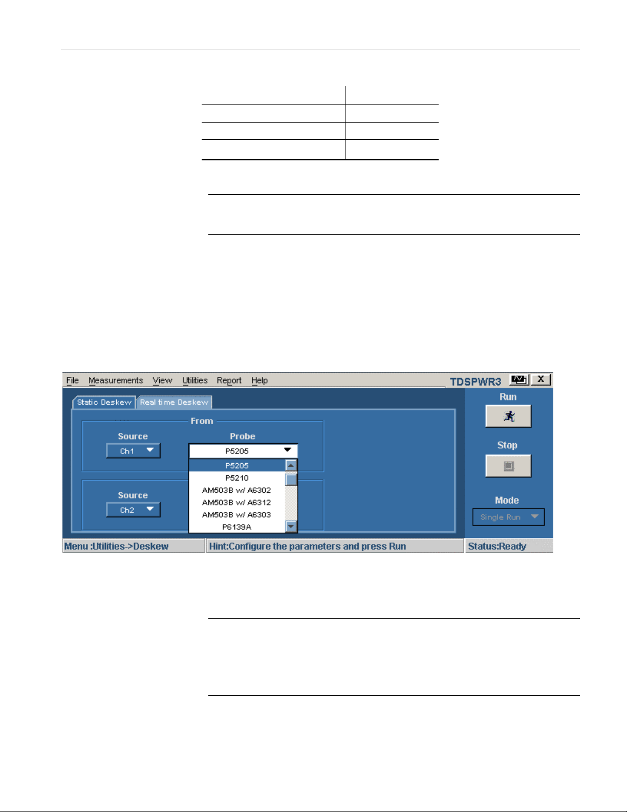
Follow these steps to perform the Static Deskew:
1. Select Utilities> Deskew> Static Deskew tab.
2. In the From panel, select the Source and the corresponding Probe type.
3. In the To panel, select the Source and the corresponding Probe type.
Figure 2-1: Static Deskew
4. Select the Run button to deskew the selected probe.
Note: Static deskew can be performed between any two channels of your choice.
Retain the From panel parameters and change the To panel parameters to
perform deskew for more than two channels.
Note: If you are using a Custom probe, the application adjusts the deskew and
sets the value when you perform static deskew.
TDSPWR3 Software Analysis Printed Help Document 17

Utilities
Deskewing in TDS5000 series Oscilloscope with an
Internal source
Use the Aux Output signal (TDS5000) and the Deskew fixture (Tektronix part
number: 067-1478-xx) to deskew the probes and channels.
Follow these steps to deskew with an internal source:
1. Connect the AUX OUT of the oscilloscope to the B side input of the deskew
fixture to deskew the voltage probe and current probe.
2. Follow the instructions of the Probe Calibration and Deskew fixture to make
the connections.
3. Set up the oscilloscope as follows:
Use the Horizontal Scale knob to set the oscilloscope to an acquisition
rate so that there are two or more samples on the deskew edge.
Use the Vertical Scale and Position knobs to adjust the signals and
display them on the screen.
Set the Record Length so that there are more samples for the edges in
the acquisition. We recommend you to set the record length to 25000
points.
4. To start the application from a TDS5000 series oscilloscopes, select File>
Run Application> Power Measurements 3.
5. Select Utilities> Deskew> Real Time Deskew> Internal Source.
6. In the From panel, set the Source to Ch1. The remaining channels are
deskewed to the Source waveform, which is the reference point.
7. In the To panel, set the Source to Ch2, the channel to be deskewed.
8. To start the deskew utility, select the Run button and confirm the operation.
9. Use Ch1 as the reference point and deskew the remaining channels.
Figure 2-2 shows an example of a deskew setup.
18 TDSPWR3 Software Analysis Printed Help Document
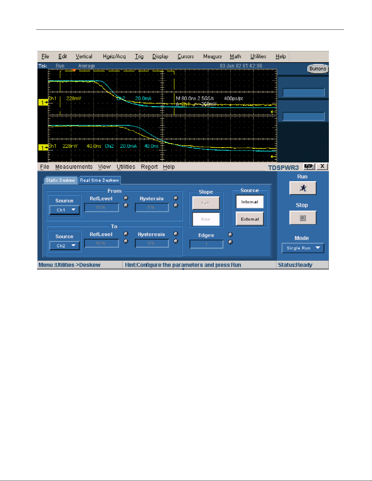
Utilities
Figure 2-2: Deskew setup
Figure 2-3 displays the results after deskewing.
TDSPWR3 Software Analysis Printed Help Document 19
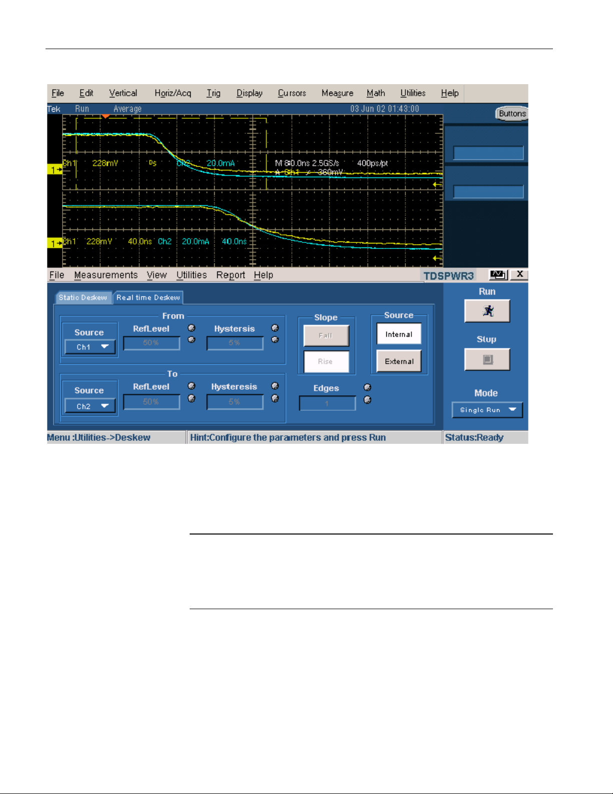
Utilities
Figure 2-3: After deskew
10. The zoomed section of the waveform available on the lower part of the
screen displays the results of the deskew operation in detail. You will see
that after performing the deskew operation, the skew is removed.
Note: The oscilloscope setup is saved before deskew and recalled after deskew. If
the acquisition setup is in Stop condition before saving the setup, the setup with
the stop condition is recalled.
When deskew recalls this setup, the application does not display the waveform.
To view the waveform, press Run or Stop button in the oscilloscope.
Deskewing in TDS7000, TDS6000 and CSA7000 series
Oscilloscopes with an Internal source
In the TDS7000 series oscilloscopes, adjust the deskew between a current probe
and voltage probe and use the deskew fixture to deskew the channels.
20 TDSPWR3 Software Analysis Printed Help Document
 Loading...