

Tektronix TDSPWR3 Reference manual
Getting Started with TDSPWR3
You can use this side of the Quick Reference to start to take
measurements with the Power Measurement and Analysis
Software (TDSPWR3). The other sidecontains a complete
menu tree for TDSPWR3 software.
NOTE. For completeoperating instructions
and General Safety information, refer to the
Online Help for the application.
4. Select the SwitchingLossoption.
9. Push the “Running Man” button to starttaking
measurements. If the measurement is successful, the
application automatically displays the results. You can
also view the results by selecting View> Results from
the application menu bar.
The TDSPWR3 Power Measurements and Analysis
software transforms a digital oscilloscope into an analysis
tool thatmeasuresand analyzes power dissipationin power
supply switching devices and magneticcomponents. It then
generates detailed test reports in customizable formats.
Performing a Switching Loss Measurement
To measure Switching Loss, follow these steps:
1. Select File> Run Application> TDSPWR3 in the
oscilloscope menu bar.
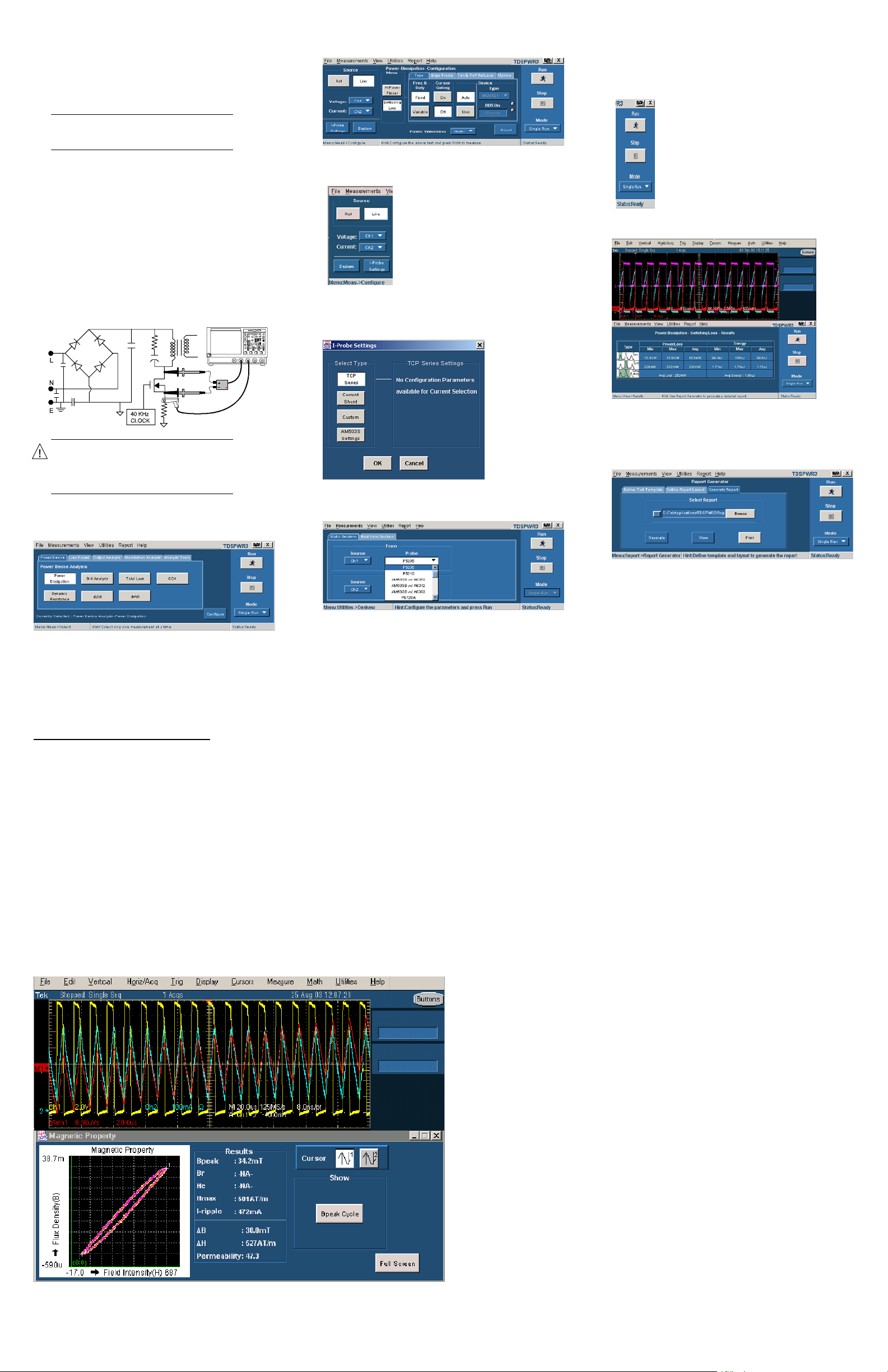
2. Connecttheprobesto the deviceunder test.For
example, the testsetup for Switching Loss is shown
below.
WARNING. When connecting to a circuit
with hazardousvoltages,referto the
warningsfortheindividual products and
verify that the probes and othercomponents
are used within their ratings.
3. In the Power Devicetab, select Power Dissipation. Press
Configure.
5. Configurethe options in the common configuration
panel.
10. The application displays results for the measurement.
6. Select the Source and assign the Voltageand Current
channels.
7. Set the appropriateI-Probe settings.
11. To generatea report, select Report> Report Generator.
12. Select the template in the GenerateReport tab.
13. Select the Generate button to post the test data to the
template.
8. Select the Deskew option or select Utilities>Deskew to
deskew.
For up-to-date information on Tektronix oscilloscope
solutions for Power Measurement, access the
www.tektronix.com/Measurement/scopes/
TDSPWR3 Ordering Information
This applicationsupports the TDS5000B, TDS5000,
TDS6000C
TDS7000
oscilloscopes; refer to the Optional ApplicationsSoftware
on Windows BasedOscilloscopes Installation Manual for a
complete listof supported models. The applicationsCD
includes a PDF file of the installation manual.
If you order Option PW3 with a new oscillscope:
H Power Analysis and Measurements Software is installed
To order an upgrade for an existingoscilloscope:
H OrdertheTDS5BUP Option PW3
H Order the TDS5UP Option PW3
H OrdertheTDS6BUP Option PW3
H Order the TDS6UP Option PW3
1
,TDS6000B1, TDS60001, TDS7000B1,
1
, CSA7000B1, and CSA70001series
and enabled
web page.
H OrdertheTDS7BUP Option PW3
H Order the TDS7UP Option PW3
H OrdertheCSA7BUP Option PW3
H Order the CSA7UP Option PW3
Recommended Accessories
Opt. 3M for TDS5000B series
Opt. 2M for TDS5000 series
Opt 2M or 3M for TDS6000B series
Opt 2M, 3M, or 4M for TDS7000B or CSA7000B series
Deskew Fixture -- 067-1478-00
CurrentProbe -- Order TCP202, TCPA300, TCPA400 or
AM503B with A63XX probes
DifferentialProbe -- Order P5205, P5210, P5200 and
ADA400A
1
Probe adapter -- TCA--1 MEG, while using 1 MΩ voltage
probeswitha TekScopeand TekConnectdevices.
TDSPWR3
Power Measurement and Analysis
Reference
www.tektronix.com
*P071139703*
071-1397-04

TDSPWR3 Menu Tree
Recall Default
Recall
Save
File
Common
Configuration
Options
Recently Recalled
Recently Saved
Preferences
Minimize
Exit
Source
Voltage
Current
Live*
Ref
Acquisition Alert Message
Last Recalled Settings
SOA Plot in Full Screen Mode
TCP
I--Probe
Settings
Series
Current
Shunt
Custom
AM503S
Settings
Selection
Power Dissipation
BH Analysis
Total Loss
SOA
Measurements configuration
Hi Power Finder
Switching Loss
Magnetic Loss
Inductance
I vs V Integral Plot
Magnetic Property
Source
Source Contd.
Switching Loss
Ton/Toff RefLevel
SOA Normal
SOA Gated
SOA DPO
Power Waveform
Enable Mask
Mask Editor
Tab
Type
Edge Trigger
Ton/Toff RefLevel
Options
Cursor Gating
Math Destination
Switching Loss
Magnetic Loss
Switching Loss
Device
Define Ton/Toff
Units
Edge Source
Units
Ref Level
Hysteresis
Math Destination
Tab
Type
RefLevel
Phy Chars
Multiple Windings
Units
RefLevel
Hysteresis
Cursor Gating
Device
Options
Math Destination
Freq/Duty
Cursor Gating
Windings
Units
Edge Source
Ref Level
Hysteresis
Units
Units
Num of Turns
X Section Area
Magnetic Length
Current 2
Current 3
Num of Turns
Measurements
Select
Configure
Tab
Power Device
Line Power
Output Analysis
Dynamic
Resistance
di / dt
dv / dt
Power
Quality
Current
Harmonics
Total Power
Quality
Ripple
Line
Ripple
Switching
Real Time Math Destination
Average Math Destination
Configuration
Math Destination
Source
Power Waveform Destination
Energy Waveform Destination
Standard
I--Probe
Waveform Destination
Ripple Frequency
Deskew
Tab
Coupling
Bandwidth
Acquisition Mode
Switching Frequency
Line Voltage
Math1|Math2|Math3|Math4
Math1|Math2|Math3|Math4
Math1|Math2|Math3|Math4
IEC 6100--3--2
Amd 14
MIL 1399
Line Freq
Harmonic Table
Select Class
Line Frequency
Transfer Impedance Table
Power
Energy
50 Hz, 60 Hz, 400 Hz
AC -- DC
20 MHz, 250 MHz, Full
High Resolution, Pk Detect, Sample
Line Voltage Source
Max Line Voltage
Line Freq
Harmonic Table
Select Class
Controls
Filter
Modulation Analysis
Analysis Tools
View
Utilities
Report
Help
* You can also select Math channels with Live signals.
Results
Deskew
SOA Overlay
Report Generator
Help Topics
About TDSPWR3
Static
Real Time
De fine Te st Tem plate
Define Report LayOut
Generate Report
Spectral
Analysis
From
To
Turn--On Time
Source
Frequency
Window Type
RBW
Options
Output Voltage
Max Turn--On Time
Converter Selection
Pulse Width
Duty Cycle
Clock Period
Frequency
Modulation
Source
Ref Destination
Ref Level
Polarity
Source
Ref Destination
Ref Level
Polarity
Edge
Source
Ref Destination
Ref Level
Edge
Source
Ref Level
Ref Destination
Edge
Output 1 | Output 2 | O utput 3
Max Turn--On Time
AC -- DC
AC -- DC
Frequency
Level
Percentage
Positive
Negative
Rise
Fall
Level
Percentage
Rise
Fall
Level
Percentage
Rise
Fall
Copyright Tektronix,Inc.
 Loading...