

Tektronix TDSPSM1 User Manual

User Manual
TDSPSM1
Processor Specifications Measurements Application
071-0581-00
This document supports software version 1.0.0
and above.
Warning
The servicing instructions are for use by
qualified personnel only. To avoid personal
injury, do not perform any servicing unless you
are qualified to do so. Refer to all safety
summaries prior to performing service.

Copyright © T ektronix, Inc. All rights reserved. Licensed software products are owned by Tektronix or its suppliers and
are protected by United States copyright laws and international treaty provisions.
Use, duplication, or disclosure by the Government is subject to restrictions as set forth in subparagraph (c)(1)(ii) of the
Rights in T echnical Data and Computer Software clause at DFARS 252.227-7013, or subparagraphs (c)(1) and (2) of the
Commercial Computer Software – Restricted Rights clause at F AR 52.227-19, as applicable.
T ektronix products are covered by U.S. and foreign patents, issued and pending. Information in this publication supercedes
that in all previously published material. Specifications and price change privileges reserved.
Printed in the U.S.A.
T ektronix, Inc., P.O. Box 1000, Wilsonville, OR 97070–1000
TEKTRONIX and TEK are registered trademarks of T ektronix, Inc.

WARRANTY
T ektronix warrants that the media on which this software product is furnished and the encoding of the programs on the media
will be free from defects in materials and workmanship for a period of three (3) months from the date of shipment. If a
medium or encoding proves defective during the warranty period, T ektronix will provide a replacement in exchange for the
defective medium. Except as to the media on which this software product is furnished, this software product is provided “as
is” without warranty of any kind, either express or implied. T ektronix does not warrant that the functions contained in this
software product will meet Customer’s requirements or that the operation of the programs will be uninterrupted or error-free.
In order to obtain service under this warranty, Customer must notify Tektronix of the defect before the expiration of the
warranty period. If T ektronix is unable to provide a replacement that is free from defects in materials and workmanship
within a reasonable time thereafter, Customer may terminate the license for this software product and return this software
product and any associated materials for credit or refund.
THIS WARRANTY IS GIVEN BY TEKTRONIX IN LIEU OF ANY OTHER WARRANTIES, EXPRESS OR
IMPLIED. TEKTRONIX AND ITS VENDORS DISCLAIM ANY IMPLIED WARRANTIES OF
MERCHANTABILITY OR FITNESS FOR A PAR TICULAR PURPOSE. TEKTRONIX’ RESPONSIBILITY TO
REPLACE DEFECTIVE MEDIA OR REFUND CUSTOMER’S PAYMENT IS THE SOLE AND EXCLUSIVE
REMEDY PROVIDED TO THE CUSTOMER FOR BREACH OF THIS WARRANTY. TEKTRONIX AND ITS
VENDORS WILL NOT BE LIABLE FOR ANY INDIRECT , SPECIAL, INCIDENTAL, OR CONSEQUENTIAL
DAMAGES IRRESPECTIVE OF WHETHER TEKTRONIX OR THE VENDOR HAS ADVANCE NOTICE OF
THE POSSIBILITY OF SUCH DAMAGES.


Table of Contents
Getting Started
Operating Basics
Related Documentation vii. . . . . . . . . . . . . . . . . . . . . . . . . . . . . . . . . . . . . . . . . . . .
Conventions vii. . . . . . . . . . . . . . . . . . . . . . . . . . . . . . . . . . . . . . . . . . . . . . . . . . . . .
Contacting T ektronix viii. . . . . . . . . . . . . . . . . . . . . . . . . . . . . . . . . . . . . . . . . . . . . .
Product Description 1. . . . . . . . . . . . . . . . . . . . . . . . . . . . . . . . . . . . . . . . .
Compatibility 1. . . . . . . . . . . . . . . . . . . . . . . . . . . . . . . . . . . . . . . . . . . . . . . . . . . .
Requirements and Restrictions 2. . . . . . . . . . . . . . . . . . . . . . . . . . . . . . . . . . . . . . .
Updates Through a Web Browser 2. . . . . . . . . . . . . . . . . . . . . . . . . . . . . . . . . . . .
Accessories 2. . . . . . . . . . . . . . . . . . . . . . . . . . . . . . . . . . . . . . . . . . . . . . . . . . . . . .
Installation 3. . . . . . . . . . . . . . . . . . . . . . . . . . . . . . . . . . . . . . . . . . . . . . . .
Installing the Application 3. . . . . . . . . . . . . . . . . . . . . . . . . . . . . . . . . . . . . . . . . . .
Connecting to a System Under T est 4. . . . . . . . . . . . . . . . . . . . . . . . . . . . . . . . . . .
Operating Basics 5. . . . . . . . . . . . . . . . . . . . . . . . . . . . . . . . . . . . . . . . . . .
Application Menu Structure 5. . . . . . . . . . . . . . . . . . . . . . . . . . . . . . . . . . . . . . . . .
Main and Side Menus 5. . . . . . . . . . . . . . . . . . . . . . . . . . . . . . . . . . . . . . . . . .
Common Menu Items 6. . . . . . . . . . . . . . . . . . . . . . . . . . . . . . . . . . . . . . . . . .
Utility Menus 6. . . . . . . . . . . . . . . . . . . . . . . . . . . . . . . . . . . . . . . . . . . . . . . .
Using Basic Oscilloscope Functions 6. . . . . . . . . . . . . . . . . . . . . . . . . . . . . . . . . .
Using Local Help 6. . . . . . . . . . . . . . . . . . . . . . . . . . . . . . . . . . . . . . . . . . . . .
Returning to the Application 6. . . . . . . . . . . . . . . . . . . . . . . . . . . . . . . . . . . . .
W arning Messages 7. . . . . . . . . . . . . . . . . . . . . . . . . . . . . . . . . . . . . . . . . . . . . . . .
Configuring the Display 7. . . . . . . . . . . . . . . . . . . . . . . . . . . . . . . . . . . . . . . . . . . .
Setting Up the Application 8. . . . . . . . . . . . . . . . . . . . . . . . . . . . . . . . . . . . . . . . . .
Measurement Setup 8. . . . . . . . . . . . . . . . . . . . . . . . . . . . . . . . . . . . . . . . . . . .
Display Results Setup 16. . . . . . . . . . . . . . . . . . . . . . . . . . . . . . . . . . . . . . . . . .
T aking Measurements 18. . . . . . . . . . . . . . . . . . . . . . . . . . . . . . . . . . . . . . . . . . . . .
Acquiring Waveforms 18. . . . . . . . . . . . . . . . . . . . . . . . . . . . . . . . . . . . . . . . . .
Localizing Measurements 19. . . . . . . . . . . . . . . . . . . . . . . . . . . . . . . . . . . . . . .
Viewing the Results 19. . . . . . . . . . . . . . . . . . . . . . . . . . . . . . . . . . . . . . . . . . . . . . .
Statistics 20. . . . . . . . . . . . . . . . . . . . . . . . . . . . . . . . . . . . . . . . . . . . . . . . . . . .
Graphical Formats 21. . . . . . . . . . . . . . . . . . . . . . . . . . . . . . . . . . . . . . . . . . . . .
Clearing Results 21. . . . . . . . . . . . . . . . . . . . . . . . . . . . . . . . . . . . . . . . . . . . . .
Saving and Recalling Setups 21. . . . . . . . . . . . . . . . . . . . . . . . . . . . . . . . . . . . . . . .
Save Setup 22. . . . . . . . . . . . . . . . . . . . . . . . . . . . . . . . . . . . . . . . . . . . . . . . . . .
Recall Setup 22. . . . . . . . . . . . . . . . . . . . . . . . . . . . . . . . . . . . . . . . . . . . . . . . .
Default Setup 22. . . . . . . . . . . . . . . . . . . . . . . . . . . . . . . . . . . . . . . . . . . . . . . .
Exiting the Application 23. . . . . . . . . . . . . . . . . . . . . . . . . . . . . . . . . . . . . . . . . . . .
Tutorial 25. . . . . . . . . . . . . . . . . . . . . . . . . . . . . . . . . . . . . . . . . . . . . . . . . . .
Setting Up the Oscilloscope 25. . . . . . . . . . . . . . . . . . . . . . . . . . . . . . . . . . . . . . . . .
Starting the Application 25. . . . . . . . . . . . . . . . . . . . . . . . . . . . . . . . . . . . . . . . . . . .
Loading the Reference Waveform Files 27. . . . . . . . . . . . . . . . . . . . . . . . . . . . . . . .
TDSPSM1 Processor Specifications Measurements Application User Manual
i

Table of Contents
Reference
Appendix
T aking Measurements from Two Waveforms 27. . . . . . . . . . . . . . . . . . . . . . . . . . .
T aking AC Timing Measurements 33. . . . . . . . . . . . . . . . . . . . . . . . . . . . . . . . . . . .
Stopping the Tutorial 37. . . . . . . . . . . . . . . . . . . . . . . . . . . . . . . . . . . . . . . . . . . . . .
Returning to the Tutorial 37. . . . . . . . . . . . . . . . . . . . . . . . . . . . . . . . . . . . . . . . . . .
Menu Structure 39. . . . . . . . . . . . . . . . . . . . . . . . . . . . . . . . . . . . . . . . . . . .
Parameters Reference 41. . . . . . . . . . . . . . . . . . . . . . . . . . . . . . . . . . . . . . .
Measurement Setup Menus 41. . . . . . . . . . . . . . . . . . . . . . . . . . . . . . . . . . . . . . . . .
Waveform Sources 42. . . . . . . . . . . . . . . . . . . . . . . . . . . . . . . . . . . . . . . . . . . . . . . .
Histogram Graphical Format 42. . . . . . . . . . . . . . . . . . . . . . . . . . . . . . . . . . . . . . . .
Profile Graphical Format 43. . . . . . . . . . . . . . . . . . . . . . . . . . . . . . . . . . . . . . . . . . .
Control Menu 44. . . . . . . . . . . . . . . . . . . . . . . . . . . . . . . . . . . . . . . . . . . . . . . . . . . .
Utility Menu 44. . . . . . . . . . . . . . . . . . . . . . . . . . . . . . . . . . . . . . . . . . . . . . . . . . . . .
Appendix A: Measurement Algorithms A–1. . . . . . . . . . . . . . . . . . . . . . . .
Oscilloscope Setup Guidelines A–1. . . . . . . . . . . . . . . . . . . . . . . . . . . . . . . . . . . . . . .
T est Methodology A–1. . . . . . . . . . . . . . . . . . . . . . . . . . . . . . . . . . . . . . . . . . . . . . . . .
Edge-Timing Measurements A–2. . . . . . . . . . . . . . . . . . . . . . . . . . . . . . . . . . . . . . . .
Dual Waveform Measurements A–2. . . . . . . . . . . . . . . . . . . . . . . . . . . . . . . . . . . . . .
Channel-to-Channel Delay Measurement A–2. . . . . . . . . . . . . . . . . . . . . . . . . . .
Setup Time Measurement A–2. . . . . . . . . . . . . . . . . . . . . . . . . . . . . . . . . . . . . . .
Hold Time Measurement A–3. . . . . . . . . . . . . . . . . . . . . . . . . . . . . . . . . . . . . . .
Clock-to-Output Time Measurement A–3. . . . . . . . . . . . . . . . . . . . . . . . . . . . . .
Single Waveform Measurements A–4. . . . . . . . . . . . . . . . . . . . . . . . . . . . . . . . . . . . .
High Time Measurement A–4. . . . . . . . . . . . . . . . . . . . . . . . . . . . . . . . . . . . . . .
Low Time Measurement A–4. . . . . . . . . . . . . . . . . . . . . . . . . . . . . . . . . . . . . . . .
Rise Time Measurement A–4. . . . . . . . . . . . . . . . . . . . . . . . . . . . . . . . . . . . . . . .
Fall Time Measurement A–5. . . . . . . . . . . . . . . . . . . . . . . . . . . . . . . . . . . . . . . .
Period Measurement A–5. . . . . . . . . . . . . . . . . . . . . . . . . . . . . . . . . . . . . . . . . . .
Index
ii
TDSPSM1 Processor Specifications Measurements Application User Manual

List of Figures
Table of Contents
Figure 1: TDSPSM1 Processor Specifications Measurements
Application 1. . . . . . . . . . . . . . . . . . . . . . . . . . . . . . . . . . . . . . . . . . . . .
Figure 2: Returning to the application 7. . . . . . . . . . . . . . . . . . . . . . . . .
Figure 3: Display Options side menu 8. . . . . . . . . . . . . . . . . . . . . . . . . . .
Figure 4: Simple timing diagram and positive range values 11. . . . . . . .
Figure 5: Positive range values for a Setup Time measurement 11. . . . .
Figure 6: Complex setup time and hold time with a negative
range value 12. . . . . . . . . . . . . . . . . . . . . . . . . . . . . . . . . . . . . . . . . . . . .
Figure 7: Negative Hold Time measurement and negative
range value 12. . . . . . . . . . . . . . . . . . . . . . . . . . . . . . . . . . . . . . . . . . . . .
Figure 8: Setup Time measurement with a data transition excluded
by range values 13. . . . . . . . . . . . . . . . . . . . . . . . . . . . . . . . . . . . . . . . .
Figure 9: Complex hold time and setup time with a negative
range value 13. . . . . . . . . . . . . . . . . . . . . . . . . . . . . . . . . . . . . . . . . . . . .
Figure 10: Negative Setup Time measurement and negative
range value 14. . . . . . . . . . . . . . . . . . . . . . . . . . . . . . . . . . . . . . . . . . . . .
Figure 11: Hold Time measurement with a data transition excluded
by range values 14. . . . . . . . . . . . . . . . . . . . . . . . . . . . . . . . . . . . . . . . .
Figure 12: How to set voltage reference levels 15. . . . . . . . . . . . . . . . . . .
Figure 13: Control menu 19. . . . . . . . . . . . . . . . . . . . . . . . . . . . . . . . . . . . .
Figure 14: Example of the results display formats 20. . . . . . . . . . . . . . . .
Figure 15: Save/Recall menu 22. . . . . . . . . . . . . . . . . . . . . . . . . . . . . . . . .
Figure 16: Exit menu 23. . . . . . . . . . . . . . . . . . . . . . . . . . . . . . . . . . . . . . . .
Figure 17: Starting the application 26. . . . . . . . . . . . . . . . . . . . . . . . . . . .
Figure 18: TDSPSM1 application initial display 26. . . . . . . . . . . . . . . . .
Figure 19: From Edge menu, source 28. . . . . . . . . . . . . . . . . . . . . . . . . . .
Figure 20: To Edge menu, source 28. . . . . . . . . . . . . . . . . . . . . . . . . . . . . .
Figure 21: Ch-Ch Delay setup complete 29. . . . . . . . . . . . . . . . . . . . . . . .
Figure 22: Ch-Ch Delay lesson: Statistics readout 29. . . . . . . . . . . . . . . .
Figure 23: Histogram format menu 30. . . . . . . . . . . . . . . . . . . . . . . . . . . .
Figure 24: Ch-Ch Delay lesson: Histogram format 31. . . . . . . . . . . . . . .
Figure 25: Profile format menu 32. . . . . . . . . . . . . . . . . . . . . . . . . . . . . . .
Figure 26: Ch-Ch Delay lesson: Profile format 33. . . . . . . . . . . . . . . . . .
TDSPSM1 Processor Specifications Measurements Application User Manual
iii

Table of Contents
List of Tables
Figure 27: Input menu voltage reference levels 34. . . . . . . . . . . . . . . . . .
Figure 28: AC Timing setup complete 34. . . . . . . . . . . . . . . . . . . . . . . . . .
Figure 29: AC Timing lesson, Period measurement: Statistics
readout 35. . . . . . . . . . . . . . . . . . . . . . . . . . . . . . . . . . . . . . . . . . . . . . . .
Figure 30: All AC Timing measurements selected 36. . . . . . . . . . . . . . . .
Figure 31: All AC Timing measurements lesson: Statistics readout 36. .
Figure 32: Application-specific menu structure 39. . . . . . . . . . . . . . . . . .
Figure 33: Control and Utility menu structures 40. . . . . . . . . . . . . . . . . .
Table 1: Channel assignments 4. . . . . . . . . . . . . . . . . . . . . . . . . . . . . . . .
Table 2: Common menu items 6. . . . . . . . . . . . . . . . . . . . . . . . . . . . . . . .
Table 3: Utility menus 6. . . . . . . . . . . . . . . . . . . . . . . . . . . . . . . . . . . . . .
Table 4: Display options 7. . . . . . . . . . . . . . . . . . . . . . . . . . . . . . . . . . . . .
Table 5: Measurements 8. . . . . . . . . . . . . . . . . . . . . . . . . . . . . . . . . . . . .
Table 6: AC Timing measurements 9. . . . . . . . . . . . . . . . . . . . . . . . . . . .
Table 7: Setup menus and waveform source side menus 10. . . . . . . . . .
Table 8: Waveform definition side menu items 16. . . . . . . . . . . . . . . . . .
Table 9: Results display formats 16. . . . . . . . . . . . . . . . . . . . . . . . . . . . . .
Table 10: Histogram format side menu items 17. . . . . . . . . . . . . . . . . . .
Table 11: Profile format side menu items 17. . . . . . . . . . . . . . . . . . . . . . .
Table 12: Control menu items 18. . . . . . . . . . . . . . . . . . . . . . . . . . . . . . . .
Table 13: Setup menus and parameters 41. . . . . . . . . . . . . . . . . . . . . . . .
Table 14: Waveform source parameters 42. . . . . . . . . . . . . . . . . . . . . . . .
Table 15: Histogram format parameters 42. . . . . . . . . . . . . . . . . . . . . . .
Table 16: Profile format parameters 43. . . . . . . . . . . . . . . . . . . . . . . . . .
Table 17: Control menu parameters 44. . . . . . . . . . . . . . . . . . . . . . . . . . .
Table 18: Utility menus and parameters 44. . . . . . . . . . . . . . . . . . . . . . .
iv
TDSPSM1 Processor Specifications Measurements Application User Manual
General Safety Summary
Review the following safety precautions to avoid injury and prevent damage to
this product or any products connected to it. To avoid potential hazards, use this
product only as specified.
Only qualified personnel should perform service procedures.
While using this product, you may need to access other parts of the system. Read
the General Safety Summary in other system manuals for warnings and cautions
related to operating the system.
Connect and Disconnect Properly . Connect the probe output to the measurement
instrument before connecting the probe to the circuit under test. Disconnect the
probe input and the probe ground from the circuit under test before disconnecting
the probe from the measurement instrument.
Do not apply a potential to any terminal, including the common terminal, that
exceeds the maximum rating of that terminal.
Symbols and Terms
T erms in this Manual. This term may appear in this manual:
WARNING. Warning statements identify conditions or practices that could result
in injury or loss of life.
TDSPSM1 Processor Specifications Measurements Application User Manual
v

General Safety Summary
vi
TDSPSM1 Processor Specifications Measurements Application User Manual

Preface
Related Documentation
This manual contains operating information for the TDSPSM1 Processor
Specifications Measurements Application. The manual consists of the following
chapters:
H The chapter Getting Started briefly describes the TDSPSM1 Processor
Specifications Measurements Application, lists oscilloscope compatibility,
and provides installation instructions.
H The chapter Operating Basics covers basic operating principles of the
application and includes a tutorial that teaches you how to set up the
application to acquire a waveform, take measurements, and view the results.
H The chapter Reference includes a diagram of the menu structure and
descriptions of parameters.
H The appendix Measurement Algorithms contains information on measure-
ment guidelines and on how the application takes the measurements.
Conventions
The user manual for your oscilloscope provides general information on how to
operate the oscilloscope.
This manual uses the following conventions:
H This manual refers to the TDSPSM1 Processor Specifications Measurements
Application as the TDSPSM1 application or as the application.
H When steps require that you make a sequence of selections using front-panel
controls and menu buttons, an arrow ( ➞
front panel button and a menu, or between menus. Names that are for a main
menu or side menu item are clearly indicated: Press VERTICAL MENU ➞
Coupling (main) ➞ DC (side) ➞ Bandwidth (main) ➞ 250 MHz (side).
) marks each transition between a
TDSPSM1 Processor Specifications Measurements Application User Manual
vii

Preface
Contacting Tektronix
Product
Support
Service
Support
For other
information
To write us Tektronix, Inc.
For application-oriented questions about a Tektronix measurement product, call toll free in North America:
1-800-TEK-WIDE (1-800-835-9433 ext. 2400)
6:00 a.m. – 5:00 p.m. Pacific time
Or contact us by e-mail:
tm_app_supp@tek.com
For product support outside of North America, contact your
local Tektronix distributor or sales office.
Contact your local Tektronix distributor or sales office. Or visit
our web site for a listing of worldwide service locations.
http://www.tektronix.com
In North America:
1-800-TEK-WIDE (1-800-835-9433)
An operator will direct your call.
P.O. Box 1000
Wilsonville, OR 97070-1000
viii
TDSPSM1 Processor Specifications Measurements Application User Manual

Getting Started

Product Description
The TDSPSM1 Processor Specifications Measurements Application is a
Java-based application that enhances basic capabilities of TDS oscilloscopes.
The application offers many of the same timing measurements, but does not
require any external equipment or lengthy procedures that may be prone to error.
Oscilloscopes can take only one measurement in an acquisition waveform. The
TDSPSM1 application can take and accumulate measurements throughout an
entire waveform effectively taking cycle-to-cycle timing measurements.
The application can display the measurement results in a numeric format as
statistics and in two graphical formats as a histogram or profile plot.
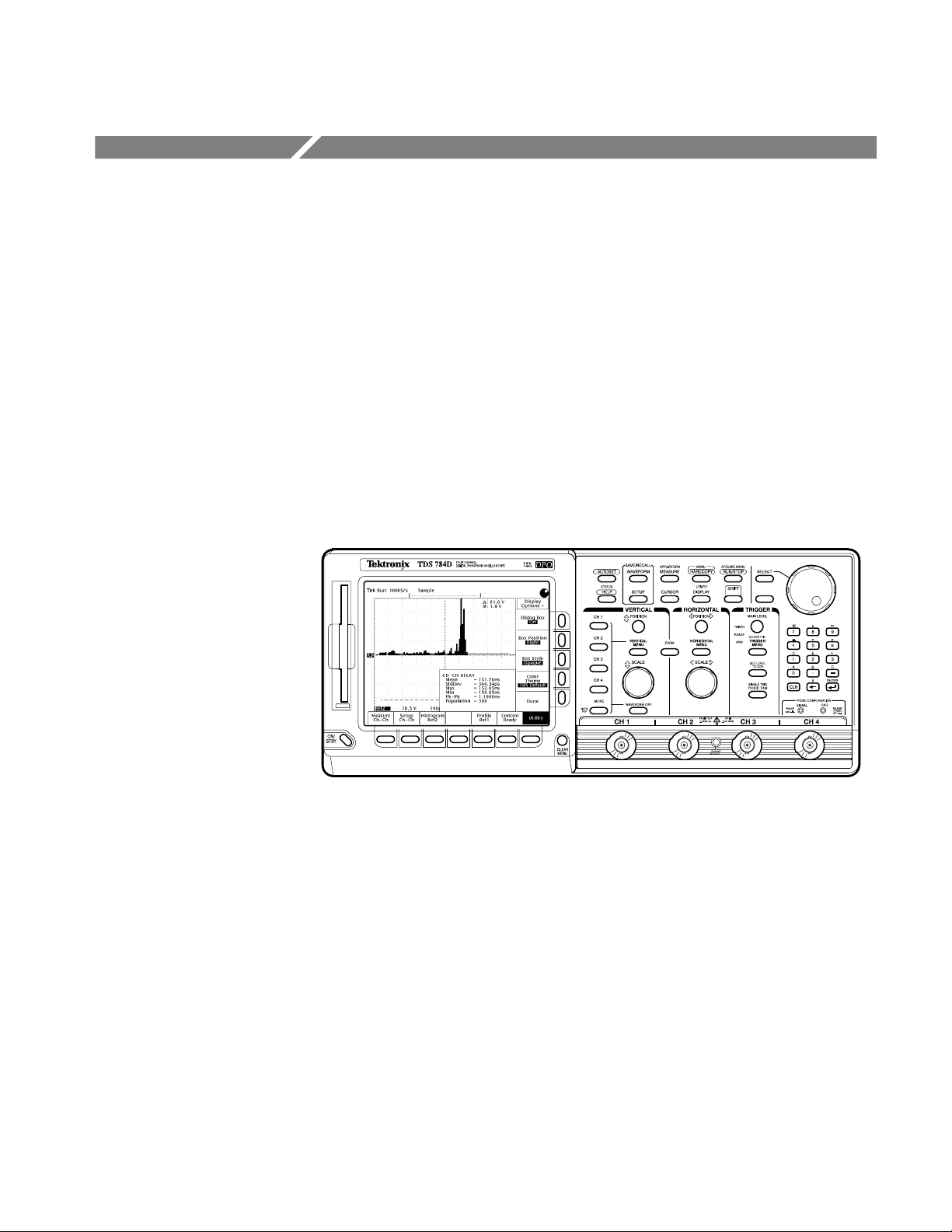
Figure 1 shows an example of the results of a Channel-to-Channel Delay
measurement.
Figure 1: TDSPSM1 Processor Specifications Measurements Application
Compatibility
The Processor Specifications Measurements Application is compatible with the
following Tektronix oscilloscopes:
H All TDS 500D and 700D Digital Phosphor Oscilloscopes with Option HD
(hard disk drive) or Option 2M (hard disk drive plus 8 MB record length)
H TDS 600C Digitizing Oscilloscopes with an Option HD (hard disk drive)
H TDS 700C Color Digitizing Oscilloscopes serial number B020100 and up,
with Option HD (hard disk drive) or Option 2M (hard disk drive plus 8 MB
record length), and with firmware version 5.2e and up
TDSPSM1 Processor Specifications Measurements Application User Manual
1

Product Description
For a current list of compatible oscilloscopes, check the Tektronix, Inc. web site,
http://www.tektronix.com/Measurement/scopes/index.html in the Software and
Drivers category.
Requirements and Restrictions
The TDS Run-Time Environment V1.1 and above must be installed on the
oscilloscope to operate the Processor Specifications Measurements Application.
The application does not support control by external GPIB commands.
Updates Through a Web Browser
You can find information about this and other applications at the Tektronix, Inc.
web site, http://www.tektronix.com/Measurement/scopes/index.html in the
Software and Drivers category. Check this site for application updates that you
can download and for free applications.
Accessories
To install an application update, you will need to download it from the Tektronix
ftp site to a hard disk, copy it to a blank DOS-formatted floppy disk, and then
install it on your oscilloscope.
NOTE. More information about changes to the application or installation is in a
Readme.txt file on the ftp site. You should read it before you continue.
To copy the application from a web browser, follow these steps:
1. Access the ftp site at ftp://ftp.tek.com/mbd/support/00–index.html#1.
2. Scroll through the files to the TDSPSM1 application, select the file, and
download it to your hard disk drive. If necessary, unzip the file.
3. Copy the application from the hard disk to a blank, DOS-formatted floppy
disk.
4. Follow the Installing the Application procedure on page 3.
There are no standard accessories for this product.
2
TDSPSM1 Processor Specifications Measurements Application User Manual

Installation
The TDSPSM1 floppy disk contains the Processor Specifications Measurements
Application. You can download updates, if any, from the Tektronix ftp site
through a web browser.
NOTE. To operate the Processor Specifications Measurements Application, the
TDS Run-Time Environment V1.1 or above must be installed on your oscilloscope.
Installing the Application
To install the application from the floppy disk to your oscilloscope, follow these
steps:
1. Power off the oscilloscope.
NOTE. Additional information about the application or installation is located in a
Readme.txt file on the floppy disk. You should insert the floppy disk into a
DOS-based personal computer and read the Readme.txt file before you continue.
If you are updating the application, the Readme.txt file on the Tektronix ftp site
supercedes the Readme.txt file on the TDSPSM1 floppy disk.
2. Insert the disk in the floppy disk drive and power on the oscilloscope.
NOTE. To verify that the TDS Run-Time Environment V1.1 or above is installed,
watch for the name to appear at the top of the display when you power on the
oscilloscope. If it does not appear, contact your local Tektronix sales office.
After performing the power-up selftest, the oscilloscope automatically begins
the installation procedure.
As the application loads from the disk, the oscilloscope displays a clock icon
to indicate that it is busy. Also, the floppy disk drive LED is on, indicating
activity. If the clock icon continues to display after the floppy disk LED has
gone out, a problem has occurred with the installation. Repeat the above
procedure. If the problem persists, contact your Tektronix representative.
When the installation is complete, an Installation Complete message
displays.
TDSPSM1 Processor Specifications Measurements Application User Manual
3
Installation
3. Remove the floppy disk and cycle the power to the oscilloscope.
Connecting to a System Under Test
You can use any compatible probe to connect between your System Under Test
(SUT) and the oscilloscope. The connection is usually to a clock signal.
Most measurements require two waveforms. The AC Timing measurements only
require one waveform.
WARNING. To avoid electric shock, you must ensure that power is removed from
the SUT before attaching a probe to it. Do not touch exposed conductors except
with the properly rated probe tips. Refer to the probe manual for proper use.
Power down the SUT before connecting the probe to it.
Table 1 shows the default channel-to-waveform assignments.
T able 1: Channel assignments
Channel or reference Waveform assignment
Ch 1 Principal waveform, such as the Clock signal
Ch 2 Relative waveform, usually data
Ref1 Profile graphical format
Ref2 Histogram graphical format
4
TDSPSM1 Processor Specifications Measurements Application User Manual

Operating Basics


Operating Basics
This section contains information on the following topics and tasks:
H Application menu structure
H Using basic oscilloscope functions
H Configuring the display
H Setting up the application
H Taking measurements
H Viewing the results
H Saving and recalling setups
H Exiting the application
Application Menu Structure
There are two types of menus in the application menu structure: main menus and
side menus. Some side menus contain common menu items as shown in Table 2.
Main and Side Menus
The main menu names appear in the bottom of the display and the side menu
names appear on the right side of the display. To see the complete application
menu structure, refer to Figure 32 on page 39.
When you press the front-panel button associated with a main menu, the side
menu changes. In many cases, when you press a side menu, new side menu items
appear. As an example, the next figure shows you how to access the Help
selections through the main Utility menu and the Help side menu.
Main menu Side menu Side menu item
Utility
Help
First Page
Next page
Previous page
Last Page
Quit Help
TDSPSM1 Processor Specifications Measurements Application User Manual
5

Operating Basics
Common Menu Items
Utility Menus
Table 2 lists common side menu items.
T able 2: Common menu items
Menu item Description
Cancel Cancels the message being displayed.
Done Indicates that you are through making changes to that set of side menus. The
application returns to the previous menu.
OK Confirms the action.
Table 3 lists the Utility menus.
T able 3: Utility menus
Utility name Description
Help Accesses the online help information and view various pages.
Exit Exits the application.
Save/Recall Setup Accesses the save and the recall menus for application setups.
Display Options Accesses other menus where you can change display settings, such as
the message box location on the display.
Using Basic Oscilloscope Functions
You can use the Utility menu to access help information about the application.
You can also use other oscilloscope functions and easily return to the application.
Using Local Help
Returning to the
Application
The application includes local help information about the measurements modes,
with some explanation of the individual controls.
To display the local help, follow these steps:
1. Press Utility (main) ➞ Help (side).
2. Use the side menu buttons to navigate through the help.
You can easily switch between the TDSPSM1 application and other oscilloscope
functions.
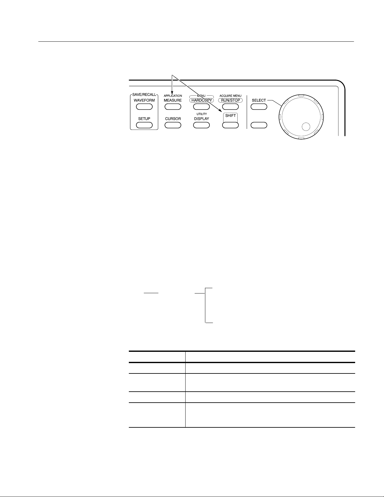
To access other oscilloscope functions, press the desired front panel control. To
return to the application, push the SHIFT and then the APPLICATION frontpanel menu buttons as shown in Figure 2.
6
TDSPSM1 Processor Specifications Measurements Application User Manual
Warning Messages
Operating Basics
Push the SHIFT and then the APPLICATION button to return to the application.
Figure 2: Returning to the application
All timing measurements provide a warning if the input conditions do not
support accurate measurements. For example, the Period measurement warns you
if you do not have at least two cycle-start edges in the acquired waveform.
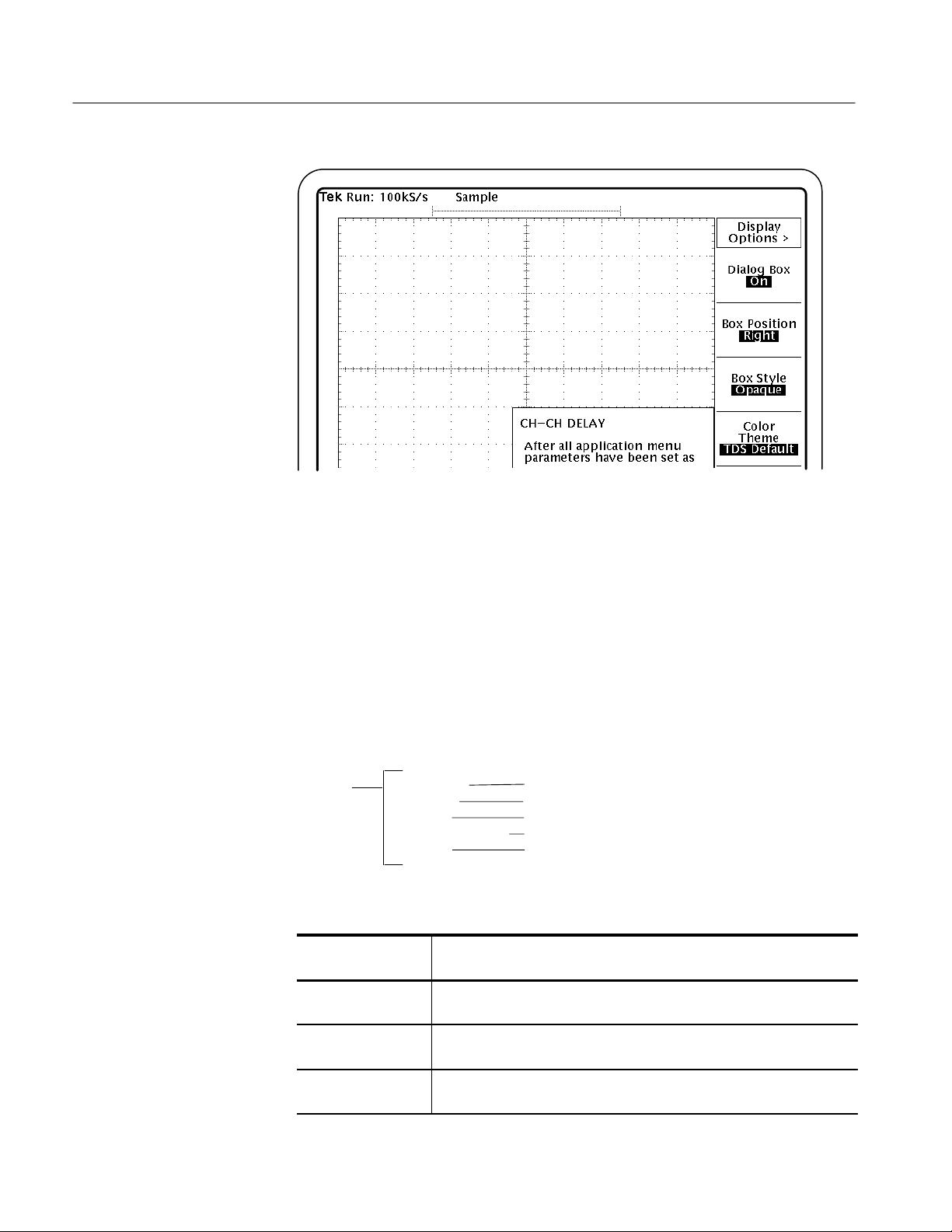
Configuring the Display
You can change how dialog boxes appear on your oscilloscope, as well as the
color of waveforms. The next figure shows how to access the display options and
Table 4 lists the options with a brief description of each.
Main menu Side menu Side menu item
Utility Display Options
Dialog Box
Box Position
Box Style
Color Theme
Done
T able 4: Display options
Display option Description
Dialog box (visibility)
Box position* Select where on the display to position dialog boxes: Left, Middle, or
Box style Select the style of dialog boxes to be Opaque or Transparent.
Color Theme Select a set of colors for waveforms and dialog boxes. The various
* Box position is fixed when taking AC Timing measurements.
Select Show or Hide to make dialog boxes visible or invisible.
Right.
TDS oscilloscopes offer 14 useable colors. Your choices are based on
the color combinations available for the TDS oscilloscope in use.
TDSPSM1 Processor Specifications Measurements Application User Manual
7
Operating Basics
Figure 3: Display Options side menu
Setting Up the Application
You can set up the application to take nine measurements and to display the
results in up to three ways.
Measurement Setup
The next figure shows how to access the measurement setup menus and Table 5
lists the TDSPSM1 measurements with a brief description of each.
Main menu Side menu
Measure
T able 5: Measurements
Measurement
name
Channel-to-Channel
Delay
Side menu items
Ch–Ch Delay
Setup Time
Hold Time
Clock to Output Time
AC Timing
Description
Difference in time between individual specific points on two waveforms.
The points are defined by an edge and a voltage reference level.
Setup Ch–Ch
Setup Setup Time
Setup Hold Time
Setup Tco
Setup AC Timing
Setup Time Elapsed time between when an input signal crosses a voltage reference
level followed by the clock signal crossing its own voltage level.
Hold Time Elapsed time between when the clock signal crosses a voltage
reference level followed by an input signal crossing its own voltage level.
8
TDSPSM1 Processor Specifications Measurements Application User Manual
 Loading...