


xx
TDSHT3
ZZZ
HDMI Compliance Test Software
Printable Online Help
*P077002408*
077-0024-08


TDSHT3
HDMI Compliance Test Software
ZZZ
PrintableOnlineHelp
www.tektronix.com
077-0024-08

Copyright © Tektronix. All rights reserved. Licensed software products are owned by Tektronix or its
subsidiaries or suppliers, and are protected by national copyright laws and international treaty provisions.
Tektronix products are covered by U.S. and foreign patents, issued and pending. Information in this
publication supersedes that in all previously published material. Specifications and price change privileges
reserved.
TEKTRONIX and TEK are registered trademarks of Tektronix, Inc.
®
MATLAB
. Copyright 1984 - 2007 The MathWorks, Inc.
Contactin
g Tektronix
Tektronix, Inc.
14150 SW Karl Braun Drive
P. O . B o x 5 0 0
Beaverton, OR 97077
USA
For p roduct information, sales, service, and technical support:
In North America, call 1-800-833-9200.
Worldwide, visit www.tektronix.com to fi nd contacts in your area.

Warranty
Tektronix warrants that the media on which this software product is furnished and the encoding of the programs
on the media will be free from defects in materials and workmanship for a period of three (3) months from the
date of shipment. If any such medium or encoding proves defective during the warranty period, Tektronix will
provide a rep
product is furnished, this software product is provided “as is” without warranty of any kind, either express or
implied. Tektronix does not warrant that the functions contained in this software product will meet Customer's
requirements or that the operation of the programs will be uninterrupted or error-free.
In order to obtain service under this warranty, Customer must notify Tektronix of the defect before the
expiration of the warranty period. If Tektronix is unable to provide a replacement that is free from defects in
materials and workmanship within a reasonable time thereafter, Customer may terminate the license for this
software product and return this software product and any associated materials for credit or refund.
THIS WARRANTY IS GIVEN BY TEKTRONIX WITH RESPECT TO THE PRODUCT IN LIEU OF ANY
OTHER WARRANTIES, EXPRESS OR IMPLIED. TEKTRONIX AND ITS VENDORS DISCLAIM AN Y
IMPLIED
TEKTRONIX' RESPONSIBILITY TO REPLACE DEFECTIVE MEDIA OR REFUND CUSTOMER'S
PAYMENT IS THE SOLE AND EXCLUSIVE REMEDY PROVIDED TO THE CUSTOMER FOR
BREACH OF THIS WARRANTY. TEKTRONIX A ND ITS VENDORS WILL NOT BE LIABLE FOR
ANY INDIRECT, SPECIAL, INCIDENTAL, OR CONSEQUENTIAL DAMAGES IRRESPECTIVE OF
WHETHER TEKTRONIX OR THE VENDOR HAS ADVANCE NOTICE OF THE POSSIBILITY OF
SUCH
lacement in exchange for the defective medium. Except as to the media on which this software
WARRANTIES OF MERCHANTABILITY OR FITNESS FOR A PARTICULAR PURPOSE.
DAMAGES.
[W9b – 15AUG04]


Table of Contents
Introduction
About the TDSHT3 HDMI Compliance Test Software ........................................................ 1
Conventions .......... ................................ .................................. ............................. 4
Feedback.......................................... ................................ .................................. . 5
Getting Started
Compatibility... . . .... ..... .... . .... ..... .... . .... ..... .... . .... ..... .... . .... ... . . .... . .... .... . .... . .... .... . .... . . 7
Recommended Accessories........................................................................................ 7
Recommended Test Equipment .................................................................................. 10
Requirements and Restrictions................................................................................... 11
How to Use the Software
How to Start the Software ..... ................................ ................................ .............. 12
How to Minimize and Maximize the Software............................................................ 15
How to Return to the Software.................... ................................ .......................... 15
How to Exit the Software ...... ................................ .................................. ............ 16
Software Folders and File Names......................... .................................. ................ 17
Shortcut Keys ................................................................................................. 18
Table of Contents
Operating Basics
Software Window........................ ................................ .................................. ........ 19
Interface Controls.......................... .................................. ................................ ...... 19
Menus and Dialog Boxes
Menu Bar ...................................................................................................... 20
File Menu ............................ ................................ .................................. ........ 21
Tests Menu .................................................................................................... 22
Results Menu ............................ ................................ .................................. .... 22
Utilities Menu .... . .... ..... . .... ..... ..... ... . . ... . . .... . .... . .... . .... . .... . .... . .... . .... . .... ..... . .... .... 23
Help Menu..................................................................................................... 23
Preferences ...... .................................. ................................ ............................ 24
Selection Pane................. ................................ ................................ ................ 25
Execution Pane................................................................................................ 26
Status Bar...................................................................................................... 26
Virtual Keyboard.............................. .................................. .............................. 26
General Purpose Knob ................. ................................ ................................ ...... 28
Enable Remote Control of Test Equipment
Enable Remote Control of Test Equipment ................................................................ 29
Configure and View Equipment Connections ............................................................. 31
Configure New IP Address for GPIB-ENET .............................................................. 34
TDSHT3 HDMI Compliance Test Software Online Help i

Table of Contents
Remote Control Caution ................................... .................................. ................ 38
Remote GPIB Commands
Remote GPIB Commands ..... .................................. ................................ ............ 40
How to ...
Calculate Tbit ...................................................................................................... 41
Deskew ............................................................................................................. 45
Configure-DTG Pattern List...... ................................ ................................ ................ 46
View the Results ................................................................................................... 48
View the Result Summary ................................................................................... 48
Configure the Report ......................................................................................... 49
View the Result Details ............................ ................................ .......................... 50
View the Result Statistics .................................................................................... 50
Select a Source Test ..... ................................ ................................ .......................... 51
Select a Sink Test.................................................................................................. 52
Select a Cable Test................................................................................................. 52
Configure Parameters for the Source Tests ..................................................................... 53
Configure Parameters for the Sink Tests ........ ................................ ................................ 54
Configure Parameters for the Cable Tests................................. ................................ ...... 59
Connect the EDID Emulator for Source Tests.............................. ................................ .... 61
HDMI Test Fixtures ............................................................................................... 62
Make Connections for Source Eye Diagram ..... ................................ .............................. 64
Make Connections for Duty Cycle .................................. ................................ ............ 67
Make Connections for Rise Time................................................................................ 70
Make Connections for Fall Time................. ................................ ................................ 73
Make Connections for Clock Jitter .... ..... ..... .... . .... . .... ..... ..... .... . .... . .... ..... ..... .... . .... . .... .. 77
Make Connections for Inter-Pair Skew ....... ................................ ................................ .. 80
Make Connections for Differential Tests Select All ................... ................................ ........ 87
Make Connections for Source Intra-Pair Skew....................................... .......................... 91
Make Connections for Low Amplitude +..................... ................................ .................. 97
Make Connections for Low Amplitude -...................................................................... 103
Make Connections for Min/Max-Diff Swing Tolerance............... ................................ ...... 109
For the DDS Method . .................................. ................................ .................... 115
Make Connections for Jitter Tolerance ... . . .... . .... . .... ..... .... . .... . .... ..... ..... .... . .... . .... ... . . .... . 119
For the DDS Method . .................................. ................................ .................... 129
Make Connections for Deep Color ........ ................................ .................................. .. 134
For the DTG Method ............. ................................ ................................ .......... 135
For the DDS Method . .................................. ................................ .................... 136
Make Connections for Audio Clock Regeneratio
For the DTG Method ............. ................................ ................................ .......... 138
For the DDS Method . .................................. ................................ .................... 139
Make Connections for Audio Sample Packet Jitter . .... ..... .... . .... . .... ... . . .... . .... . .... ..... .... . .... . 141
n .......................................................... 138
ii TDSHT3 HDMI Compliance Test Software Online Help

Table of Contents
For the DTG Method ............. ................................ ................................ .......... 141
For the DDS Method . .................................. ................................ .................... 142
Make Connections for Audio Formats .................................. ................................ ...... 144
For the DTG Method ............. ................................ ................................ .......... 144
For the DDS Method . .................................. ................................ .................... 145
Make Connections for One Bit Audio......................................................................... 147
For the DTG Method ............. ................................ ................................ .......... 147
For the DDS Method . .................................. ................................ .................... 148
Make Connections for DVI Interoperability.. ... . . .... . .... .... . .... . .... . .... . .... . .... . .... ..... ..... ..... . 150
For the DTG Method ............. ................................ ................................ .......... 150
For the DDS Method . .................................. ................................ .................... 151
Make Connections for 3D Video............................................................................... 153
For the DTG Method ............. ................................ ................................ .......... 153
For the DDS Method . .................................. ................................ .................... 154
Make Connections for 4Kx2K Video.......................................................................... 156
For the DTG Method ............. ................................ ................................ .......... 156
For the DDS Method . .................................. ................................ .................... 157
Make Connections for Extended Colors and Contents .............................. ........................ 159
For the DTG Method ............. ................................ ................................ .......... 159
For the DDS Method . .................................. ................................ .................... 160
Make Connections for Character Synchronization..................................... ...................... 162
For the DTG Method ............. ................................ ................................ .......... 162
For the DDS Method . .................................. ................................ .................... 163
Make Connections for Pixel Encoding Requirements....................................................... 165
For the DTG Method ............. ................................ ................................ .......... 165
For the DDS Method . .................................. ................................ .................... 166
Make Connections for Acceptance of All Valid Packets .................................................... 168
For the DTG Method ............. ................................ ................................ .......... 168
For the DDS Method . .................................. ................................ .................... 169
Make Connect
For the DTG Method ............. ................................ ................................ .......... 171
For the DDS Method . .................................. ................................ .................... 172
Make Connections for Sink Intra-Pair Skew ................... ................................ .............. 174
For the DDS Method . .................................. ................................ .................... 180
Make Connections for Cable Eye Diagram (Passive and Active).............. ............................ 188
For the DTG Method ............. ................................ ................................ .......... 188
For the DDS Method . .................................. ................................ .................... 197
Make Connections for Cable Inter-Pair Skew................................................................ 201
View the Source Eye Diagram Sample Waveform........................................................... 206
View the Duty Cycle Sample Waveform...................... ................................ ................ 207
View the Rise Time Sample Waveform......... ................................ .............................. 208
View the Fall Time Sample Waveform........................................................................ 209
ions for Video Format Timing ............ ................................ .................... 171
TDSHT3 HDMI Compliance Test Software Online Help iii

Table of Contents
View the Clock Jitter Sample Waveform .... . .... . .... ... . . .... . .... ... . . .... . .... ... . . .... . .... ... . . .... . ... 210
View the Source Inter-Pair Skew Sample Waveform........................................................ 211
View the Differential Tests Select All Sample Waveform .................................................. 212
View the Source Intra-Pair Skew Sample Waveform........................................................ 213
View the Low Amplitude + Sample Waveform ... . .... ..... ..... .... . .... . .... . .... ..... .... . .... . .... . .... . 214
View the Low Amplitude - Sample Waveform... ..... ..... .... . .... . .... . .... . .... ... . . .... . .... . .... . .... .. 215
View the Min/Max-Diff Swing Tolerance Sample Waveform.............................................. 215
View the Jitter Tolerance Waveform .... .... . .... . .... . .... . .... .... . .... . .... . .... . .... .... . .... . .... . .... . .. 216
View the Deep Color Waveform ............................................................................... 216
View the Audio Clock Regeneration Waveform ..... .................................. ...................... 216
View the Audio Sample Packet Jitter Waveform............................................................. 216
View the Audio Formats Waveform ..................... .................................. .................... 216
View the One Bit Audio Waveform ..... ................................ ................................ ...... 216
View the DVI Interoperability Waveform .... . .... . .... ... . . .... . .... . .... . .... .... . .... . .... . .... . .... .... . . 217
View the 3D Video Waveform ................................................................................. 217
View the 4Kx2K Video Waveform ............................................................................ 217
View the Extended Colors and Contents Waveform......................................................... 217
View the Character Synchronization Waveform ............................... .............................. 217
View the Pixel Encoding Requirements Waveform........ .................................. ................ 217
View the Acceptance of All Valid Packets Waveform........................... ............................ 218
View the Video Format Timing Waveform................................................................... 218
View the Sink Intra-Pair Skew Sample Waveform .......................................................... 218
View the Cable Eye Dia gram (Passi
View the Cable Inter-Pair Skew Sample Waveform ................. .................................. ...... 218
Test the Source Eye Diagram................................................................................... 218
Test Method ................................................................................................. 224
Test the Duty Cycle...................................... ................................ ........................ 225
Test Method ................................................................................................. 228
Test the Rise Time ................... ................................ .................................. .......... 229
Test Method ................................................................................................. 2
Test the Fall Time................................................................................................ 233
Test Method ................................................................................................. 237
Test the Clock Jitter ............................................................................................. 238
Test Method ................................................................................................. 245
Test the Source Inter-Pair Skew........................ ................................ ........................ 245
Test Method ................................................................................................. 249
Test the Differential Tests Select All .......... ................................ ................................ 251
Test the Source Intra-Pair Skew........................ ................................ ........................ 255
Test Method ................................................................................................. 258
Test the Low Amplitude + .. . .... . .... . .... ..... .... . .... . .... ..... ... . . .... . .... . .... .... . .... . .... . .... ..... .. 259
Test the Low Amplitude -.. . .... .... . .... . .... .... . .... . .... ..... .... . .... . .... ..... .... . .... . .... .... . .... . .... 262
Test the Min/Max-Diff Swing Tolerance...................................................................... 265
ve or Active) Sample Waveform..................................... 218
32
iv TDSHT3 HDMI Compliance Test Software Online Help

Table of Contents
Test Method ................................................................................................. 271
Test the Jitter Tolerance......................................................................................... 273
Test Method ................................................................................................. 283
Test the Deep Color ............... ................................ ................................ .............. 285
Test Method ................................................................................................. 289
Test the Audio Clock Regeneration............................................................................ 290
Test Method ................................................................................................. 295
Test the Audio Sample Packet Jitter . . .... ... . . .... . .... ..... .... . .... . .... .... . .... . .... ... . . .... . .... ..... ... 296
Test Method ................................................................................................. 300
Test the Audio Formats ....................... ................................ ................................ .. 301
Test Method ................................................................................................. 306
Test the One Bit Audio........................ ................................ .................................. 307
Test Method ................................................................................................. 312
Test the DVI Interoperability... . .... ..... .... . .... . .... ..... .... . .... . .... . .... .... . .... . .... ..... ... . . .... . ... 313
Test Method ................................................................................................. 318
Test the 3D Video.................. .................................. ................................ ............ 319
Test Method ................................................................................................. 324
Test the 4Kx2K Video....................... ................................ ................................ .... 325
Test Method ................................................................................................. 330
Test the Extended Colors and Contents ....................................................................... 330
Test Method ................................................................................................. 335
Test the Character Synchronization............................................................................ 336
Test Method ................................................................................................. 341
Test the Pixel Encoding Requirements ........................................................................ 342
Test Method ................................................................................................. 347
Test the Acceptance of All Valid Packets ................. ................................ .................... 348
Test Method ................................................................................................. 353
Test the Video Format Timing ................................................................................. 354
Test Method ................................................................................................. 359
Test the Sink Intra-Pair Skew .................................................................................. 360
Test Method ................................................................................................. 366
Test the Cable Eye Diagram (Passive and Active)........................................................... 368
Test Method ................................................................................................. 377
Test the Cable Inter-Pair Skew ..................... ................................ ............................ 379
Test Method ................................................................................................. 384
Measurement Algorithms
Software CRU Technology ................... .................................. ................................ 385
HTML/MHT Reports
About HTML/MHT Reports ................................................................................... 391
Reports Formats..................................... ................................ ........................ 391
TDSHT3 HDMI Compliance Test Software Online Help v

Table of Contents
Sample Report......................................... .................................. .................... 392
References
Default Settings . ..... .... . .... . .... .... . .... . .... ... . . .... . .... ..... .... . .... . .... ... . . .... . .... ..... .... . .... . .. 395
Error Codes....................................................................................................... 397
Index
vi TDSHT3 HDMI Compliance Test Software Online Help

Introduction About the TDSHT3 HDMI Compliance Test Software
About the TDSHT3 HDMI Compliance Test Software
The TDSHT3 HDMI Compliance Test Software is a High Definition Multimedia Interface (HDMI)
compliance test solution. This software helps engineers perform both HDMI physical layer validation
and comp
conformance with the HDMI standards and test specifications.
liance testing. The TDSHT3 HDMI Compliance Test Software provides credible test results in
TDSHT3 HDMI Compliance Test Software Online Help 1

Introduction About the TDSHT3 HDMI Compliance Test Software
The TDSHT3 HDMI Compliance Test Software offers automated tests for:
Source
Differential Tests
Eye Diagram (see page 218) (Test ID 7-10)
Duty Cycle (see page 225) (Test ID 7-8)
Rise Time (see page 229) (Test ID 7-4)
Fall Time (see page 233) (Test ID 7-4)
ter
Clock Jit
Inter-Pair Skew (see page 245) (Test ID 7-6)
Single-Ended Tests
Intra-Pair Skew (see page 255) (Test ID 7-7)
Low Amplitude + (see page 259) (Test ID 7-2)
(see page 238) (Test ID 7-9)
Low Amplitude - (see page 262) (Test ID 7-2)
2 TDSHT3 HDMI Compliance Test Software Online Help

Introduction About the TDSHT3 HDMI Compliance Test Software
Sink
Differential Tests
Min/Max-Diff Swing Tolerance (see page 265) (Test ID 8-5)
Jitter Tolerance (see page 273) (Test ID 8-7)
Deep Color (
Audio Clock Regeneration (see page 290) (Test ID 8-21)
Audio S ample Packet Jitter (see page 296) (Test ID 8-22)
Audio Formats (see page 301) (Test ID 8-23)
One Bit Audio (see page 307) (Test ID 8-28)
DVI Interoperability (see page 313) (Test ID 8-24)
3D Video
4Kx2K Video (see page 325) (Test ID 8-30)
Extended Colors and Contents (see page 330) (Test ID 8-31)
Character Synchronization (see page 336) (Test ID 8-15 )
Pixel Encoding Requirements (see page 342) (Test ID 8-19)
Acceptance of All Valid Packets (see page 348) (Test ID 8-16 )
o Format Timing
Vide
Single-Ended Tests
Intra-Pair Skew (see page 360) (Test ID 8-6)
see page
(see page 319) (Test ID 8-29)
285) (Test ID 8-25)
(see page 354) (Test ID 8-20)
ble
Ca
Differential Tests
Cable Eye Diagram (Passive and Active) (see page 368) (Test ID 5-3)
Inter-Pair Skew (see page 379) (Test ID 5-5)
NOTE. This Cable Inter-Pair Skew test is performed only for repeater cable testing.
The software offers automatic “one-button” testing that ensures faster validation with higher reliability and
it supports only single-link HDMI device resolutions.
TDSHT3 HDMI Compliance Test Software Online Help 3

Introduction Conventions
See Also
(see page 7) Compatibility
(see page 11) Requirements and Restrictions
(see page 7) Recommended Accessories
Convention
The online
The term “Exit” refers to exiting the application and not the oscilloscope unless otherwise stated.
The waveforms used are representative and change for different settings and resolutions.
TheTDSHT3HDMIComplianceTestSoftwareisreferredtoasTDSHT3software.
The screens used are representative and may not match exactly with what you see. However, the
functionality of the software is as described.
s
help system serves as a reference on how to use the TDSHT3 HDMI Compliance Test Software.
4 TDSHT3 HDMI Compliance Test Software Online Help

Introduction Feedback
Feedback
Tektronix values your feedback on our products. To help us serve you better, please send us your
suggestions, ideas, or comments on the TDSHT3 software.
Direct your feedback via e-mail to HDMIFeedback@tek.com or FAX at (503) 627-5695 and include the
following information:
General Information
Instrumen
Probes used
Your name, company, mailing address, phone number, FAX number, e-mail id
Please indicate if you would like to be contacted by Tektronix about your suggestions or comments
t model number and hardware options, if any
Program-Specific Information
Software version number
Description of the problem such that technical support can duplicate the problem
The instrument setup file of the oscilloscope and the application are also required to identify the
problem
If possible, save the waveform on which you are performing the test as a .wfm file
NOTE. To find the software version number, click Help > About in the software.
Once you have gathered this information, you can contact technical support by e-mail. When you use
e-mail, be sure to type in the subject line “TDSHT3 HDMI Compliance Test Software Problem,” and then
attach the .wfm files.
TDSHT3 HDMI Compliance Test Software Online Help 5

Introduction Feedback
6 TDSHT3 HDMI Compliance Test Software Online Help

Getting Started Compatibility
Compatibility
For information on oscilloscope compatibility, refer to the Optional Applications Software on
Windows-Based Oscilloscopes Installation Manual, Tektronix Part Number, 077-0067-XX. The manual is
available as
aPDFfile.
Recommended Accessories
The following probes a nd test fixtures are recommended for the TDSHT3 software.
Supported Probes
P7313SMA – 13 GHz recommended differential probe
The following probes can be used with HDMI 1.2 test fixtures:
P7350 – 5 GHz differential probe
P7330 – 4 GHz differential probe
P6330 – 4 GHz differential probe
P7380 – 8 GHz differential probe
P7240 – 4 GHz single-ended probe
P7260 – 6 GHz single-ended probe
The P7350SMA – 5 GHz differential probe can only be used with the HDMI 1.2 TDR fixture and the 1.3
Efficere test fixtures (now available from Tektronix).
Supported 1.3/1.4a Test Fixtures
TF-HDMI-TPA-STX (Alternate equivalent test fixture, which consists of 1# TF-HDMI-TPA-P, 1#
TF-HDMI-TPA-CE)
TF-HDMI-TPA-S (Alternate equivalent test fixture, which consists of 1# TF-HDMI-TPA-P,2#
TF-HDMI-TPA-R,1#TF-HDMI-TPA-C, and 1#TF-HDMI-TPA-CE)
TF-HDMI-TPA-CE (Alternate equivalent test fixture, which consists of EDID PCB and 1# EDID
EEPROM
TF-HDMIC-TPA-STX (Alternate equivalent test fixture, which consists of 1# TF-HDMIC-TPA-P, 1#
TF-HDMI-TPA-CE)
TF-HDMIC-TPA-S (Alternate equivalent test fixture, which consists of 1# TF-HDMIC-TPA-P,2#
TF-HDMIC-TPA-R,1#TF-HDMI-TPA-C, and 1#TF-HDMI-TPA-CE)
TDSHT3 HDMI Compliance Test Software Online Help 7

Getting Started Recommended Accessories
TF-HDMID-TPA-P and TF-HDMID-TPA-R, available from Tektronix
TF-HDMIE-TPA-KIT, available from Tektronix
The following HDMI 1.2 test fixture
HDMI-TPA-P-DI
HDMI-TPA-P-SE
HDMI-TPA-P-TDR
HDMI-TPA-R-DI
HDMI-TPA-R-SE
HDMI-TPA-R-TDR
The fixtures are available under the Tektronix ordering system with the following part numbers:
TF-HDMI-TPA-S – HDMI Type A fixture set for Tx, Rx, and Cable testing. It includes the following:
One HDMI-TPA-P plug board with SMA cables
Two HDMI-TPA-R receptacle board with SMA cables
One HDMI-TPA-C calibration board with SMA cables
One HDMI-TPA-CE, EDID board with EDID EEPROM
TF-HDMI-TPA-STX –HDMITypeAfixture set for Tx and Rx testing. It includes the following:
One HDMI-TPA-P plug board
s can only work for limited HDMI resolutions.
One HDMI-TPA-CE, EDID board with EDID EEPROM
TF-HDMI-TPA-CE – EDID test fixture. It includes the following:
One EDID PCB
One EDID board with EDID EEPROM
TF-HDMIC-TPA-S –HDMITypeCfixture set for Tx, Rx, and Cable testing. It includes the
following:
One HDMIC-TPA-P plug board with SMA cables
Two HDMIC-TPA-R receptacle board with SMA cables
One HDMI-TPA-C calibration board with SMA cables
One HDMI-TPA-CE, EDID board with EDID EEPROM
TF-HDMIC-TPA-STX –HDMITypeAfixture set for Tx and Rx testing. It includes the following:
One HDMIC-TPA-P plug board
One HDMI-TPA-CE, EDID board with EDID EEPROM
TF-HDMID-TPA-P – HDMI Type D fixture set for Tx and Rx testing. It includes one HDMI Type D
plug board.
8 TDSHT3 HDMI Compliance Test Software Online Help

Getting Started Recommended Accessories
TF-HDMID-TPA-R –HDMITypeDfixture set for Tx, Rx, and Cable testing. It includes one
HDMITypeDreceptacleboard.
TF-HDMIE-TPA-KIT –HDMITypeEfixture set for Tx, Rx, and Cable Testing. It includes the
following:
One HDMI-TPA-P plug board with SMA cables
Two HDMI-TPA-R receptacle boards with SMA cables
Direct Synthesis
HDMI Direct Synthesis Accessory Kit 020-3018-XX is required for Direct Synthesis setup.
Connecti
vity
GPIB (recommended for DPO/DSA/MSO70000 series oscilloscopes)
USB-GPIB (HS)
E-Net Switch
TDSHT3 HDMI Compliance Test Software Online Help 9

Getting Started Recommended Test Equipment
Recommended Test Equipment
The compliance test setups use a variety of test equipment. The test setups refer to the test equipment with
generic names. Below is a list of suitable test equipment for each type of test equipment.
DTG (Data Timing Generator)
DTG5000 Ser
ies
AFG (Arbitrary Function Generator)
AFG3000 Series
AWG (Arbitrary Waveform Generator)
AWG7 000 Ser ies
Digital Oscilloscope
MSO/DPO/DSA72004 Series
MSO/DPO/DSA71604 Series
MSO/DPO/DSA71254 Series
DPO/DSA70804 Series
MSO/
10 TDSHT3 HDMI Compliance Test Software Online Help

Getting Started Requirements and Restrictions
Requirements and Restrictions
TekVISA must be installed on the oscilloscope. If you do not have TekVISA, you can download it
from www.tektronix.com/software
MATLAB Runtime must be installed on the oscilloscope. If you do not have MATLAB Runtime,
the TDSHT3 installer will install it.
.
NOTE. Do not
abnormal test results.
For Better
Before you run any test, calibrate the probes and oscilloscope for Signal Path Compensation. On the
oscillos
the oscilloscope.
If the si
a message such as “Invalid Signal.”
change the oscilloscope settings while a test is running. If you do, the software may give
and Reliable Results
cope menu bar, click Utilities > Instrument Calibration and then click Calibrate to calibrate
gnal is not connected and the noise level is less than 50 mV, the software detects and gives
TDSHT3 HDMI Compliance Test Software Online Help 11
Getting Started How to Start the Software
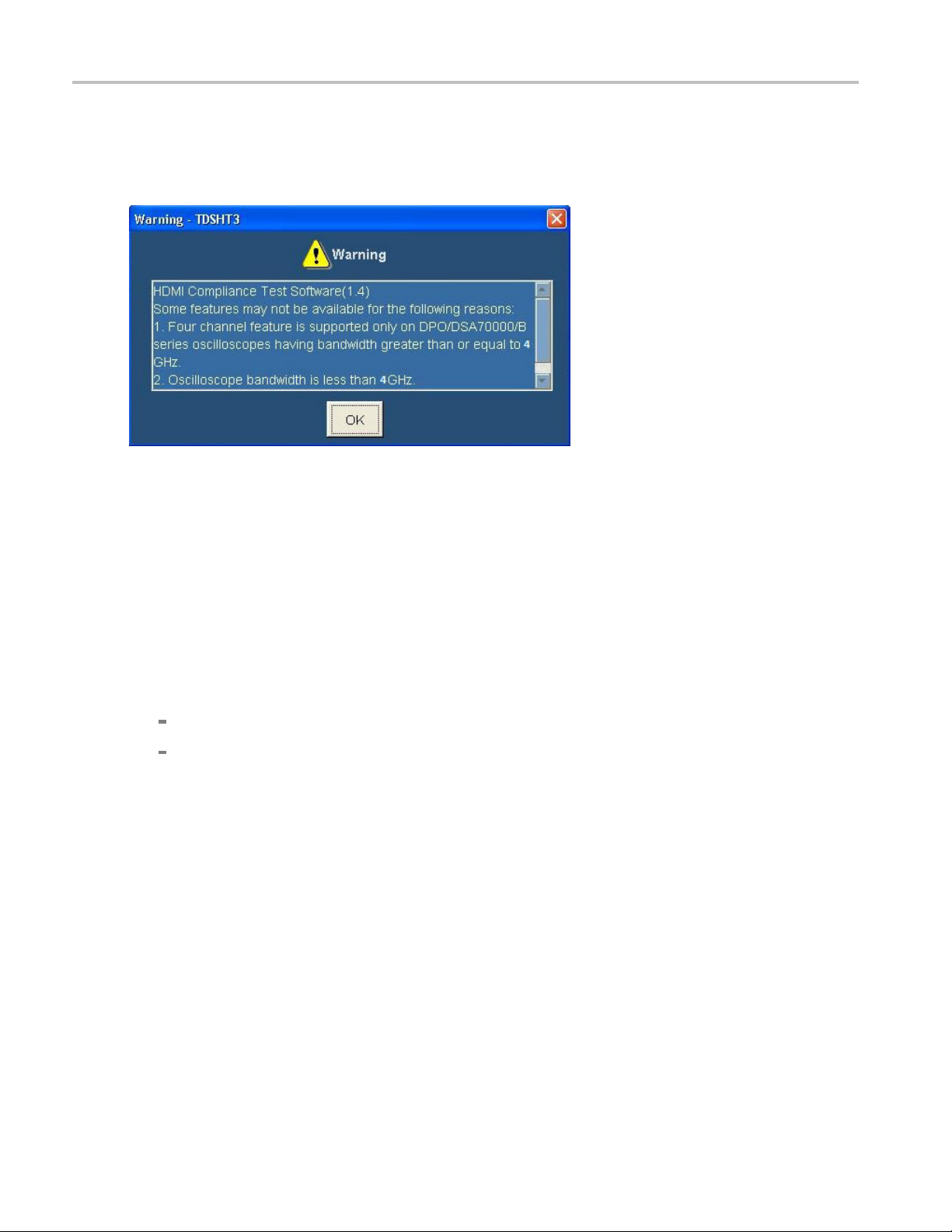
How to Start the Software
When you start the software, a warning message box may appear.
This happens due to the following reasons:
1. Four channel feature is supported only on DPO70000/B, DSA70000/B, and MSO70000 series
oscilloscopes having bandwidth greater than or equal to 4 GHz. For TDS series oscilloscopes,
only two channels are available and the other two channels are displayed as Not Conn.
2. Oscilloscope bandwidth is less than 4 GHz. For higher resolution HDMI signals, you need at least a
4 GHz oscilloscope. Your oscilloscope bandwidth is less than 4 GHz.
3. Maximum available record length for two channels is less than 16 M. For HDMI compliance
testing, you need at least a 16 M record length in two channels. This 16 M record length is installed in
the following oscilloscopes:
Option 4M a nd above in TDS series oscilloscopes
Option 2XL and above in DPO series oscilloscopes
If these options are not available (installed) in the oscilloscope, the software will run the Eye diagram
and Jitter measurements with the maximum available record length.
4. DDS method is supported only on DPO70000/B/C, DSA70000/B/C, and MSO70000/C series
oscilloscopes having bandwidth greater than or equal to 8 GHz.
5. TDSHT3 application and the DDS method option license keys are not installed. They are
running in trial mode.
6. TDSHT3 application is licensed but the DDS method option license key is not installed. The DDS
method is running in trial mode.
7. DDS m ethod option is not available, trial has expired. The DDS method trial has expired and
this option will not appear in the application.
12 TDSHT3 HDMI Compliance Test Software Online Help
Getting Started How to Start the Software
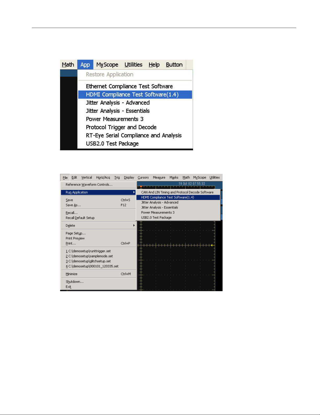
Depending on the type of oscilloscope that you have, you can start the software in different ways.
1. For supported B-series oscilloscopes, select App > HDMI Compliance Test Software(1.4).
2. For TDS7000-series oscilloscopes, select File > Run Application >HDMI Compliance Test
Software(1.4).
TDSHT3 HDMI Compliance Test Software Online Help 13

Getting Started How to Start the Software
3. For DPO/DSA/MSO70000 series oscilloscopes, select Analyze > HDMI Compliance Test
Software(1.4).
4. A splash screen indicates that the software is loading.
5. The oscilloscope display resizes to fit in the upper part of the screen. The lower part of the oscilloscope
n displays the TDSHT3 software.
scree
14 TDSHT3 HDMI Compliance Test Software Online Help
Getting Started How to Minimize and Maximize the Software
6. The software is automatically set to its default settings (see page 395).
7. If you gain access to the oscilloscope functions, the oscilloscope display appears full screen and the
TDSHT3 software recedes to the background.
How to Minimize and Maximize the Software
The software appears even when you minimize the oscilloscope display.
To minimize the software, click File > Minimize. The TDSHT3 software window minimizes to the
Windows taskbar. The upper part of the screen has the oscilloscope display and the lower part of
the screen has the desktop.
To restore the minimized window to its previous size, click its taskbar button.
To hide the window, click Hide on the top-right of the software window.
NOTE. If
fills the display.
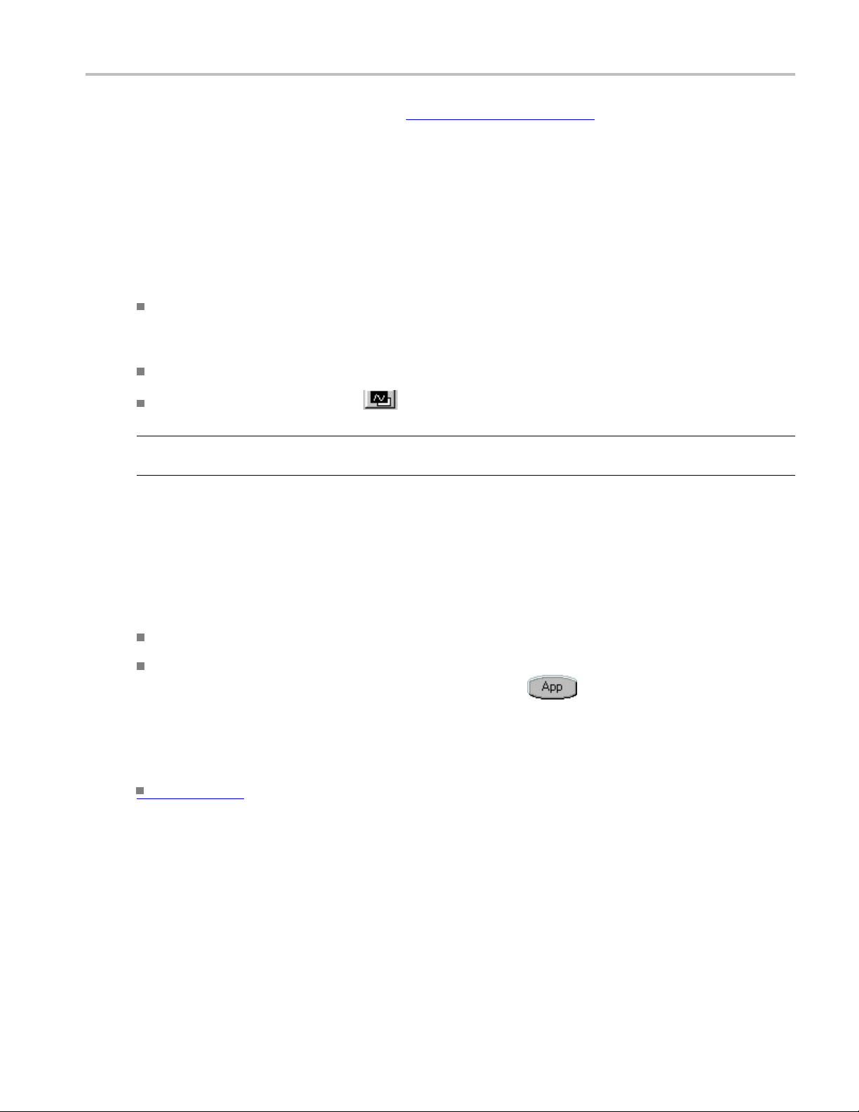
How to
When y
oscilloscope functions, do one of the following:
See Also
you click Hide, the TDSHT3 software window goes to the background and the oscilloscope
Return to the Software
ou gain access to the oscilloscope functions, the oscilloscope fills the display. To gain access to the
se either the menu bar or the toolbar mode on the oscilloscope, and then gain access to the menus.
Choo
Click App > Restore Application for B-series, click Analyze > Restore Application for
/DSA/MSO70000 series oscilloscopes, or click APP
DPO
TDS7000 series oscilloscope display to return to the software.
(see page 16) Exit
on the top right of the
TDSHT3 HDMI Compliance Test Software Online Help 15

Getting Started How to Exit the Software
How to Exit the Software
To quit the software:
On the menu bar, click File > Exit.
The Exit dialog box appears.
Click Ye s , No,orCancel. Yes is selected by default. When the software runs, it automatically changes
some osc
settings or restore the previous settings.
illoscope settings. When you quit the software, you can choose whether to retain these
NOTE. Using other methods to quit the software may result in an abnormal exit of the software.
16 TDSHT3 HDMI Compliance Test Software Online Help

Getting Started Software Folders and File Names
Software Folders and File Names
The TDSHT3 s oftware uses file name extensions to identify the file type. The following table lists the
default folder names and their purpose:
For Windows XP Oscilloscopes
Folder Purpose
C:\TekAppl
C:\TekApp
C:\TekApp
C:\TekAp
C:\TekA
C:\TekA
xxx
For Windows 7 Oscilloscopes
ications\TDSHT3v1-3
lications\TDSHT3v1-3\Images
lications\TDSHT3v1-3\Data
plications\TDSHT3v1-3\setup
pplications\TDSHT3v1-3\Demo Tools
pplications\TDSHT3v1-3\Reports
This is the software data folder.
This folder stores all the images.
This folder stores all the software data.
This folder stores all the save and recall files.
This folder stores the demo waveforms.
This folder stores the reports.
Folder Purpose
C:\Users\<Username>\Tektronix\TekApplications\TDSHT3v1-3
ers\<Username>\Tektronix\TekApplications\TD-
C:\Us
SHT3v1-3\Images
C:\Users\<Username>\Tektronix\TekApplications\TDSHT3v1-3\Data
Users\<Username>\Tektronix\TekApplications\TD-
C:\
SHT3v1-3\setup
C:\Users\Public\Tektronix\TekApplications\TDSHT3v1-3\Demo Tools
\Users\<Username>\Tektronix\TekApplications\TD-
C:
SHT3v1-3\Reports
xxx
This is the software data folder.
This folder stores all the images.
This folder stores all the software data.
This folder stores all the save and recall files .
This folder stores the demo waveforms.
This folder stores the reports.
TDSHT3 HDMI Compliance Test Software Online Help 17

Getting Started Shortcut Keys
Shortcut Keys
Menu Shortcut key
File Alt+F
Test s Alt + T
Results Alt+R
Utilities Alt+U
Help Alt+H
File > Recal
File > Recall Alt+F+R
File > Recall > First Recent Alt+F+E+1
File > Recall > S econd Recent
File > Rec
File > Recall > Fourth Recent Alt+F+E+4
File > Save Alt+F+S
File > Recall Recent Alt+F+E
File > Preferences
File > Preferences > Position Eye Mask in Center
File > Preferences > Acquisition Alert Message
File > Preferences > Jitter Tolerance (No calibration)
File > Preferences > Single Ended (With 50 ohm term) Alt+F+P+S
File > Preferences > Set the probe control to internal 3.3 V Alt+F+P+C
e > Minimize
Fil
File > Exit Alt+F+X
Tests > Select Alt+T+S
Tests > Select > Source Alt+T+S+S
Tests > Select > Sink Alt+T+S+K
Tests > Select > Cable Alt+T+S+C
Test s > C onfigure Alt+T+C
Tests > Connect
Tests > View Waveform
Results > Summary Alt+R+S
Results > Details Alt+R+D
Utilities > Deskew Alt+U+D
Utilities > DTG Pattern List
Help > Help Topics Alt+H+T
Help > About HDMI Alt+H+A
xxx
l Compliance Default
all > Third Recent
Alt+F+D
Alt+F+E+
Alt+F+E+
P
Alt+F+
+P+M
Alt+F
+P+A
Alt+F
F+P+J
Alt+
+F+M
Alt
Alt+T+N
Alt+T+V
Alt+U+P
2
3
18 TDSHT3 HDMI Compliance Test Software Online Help

Operating Basics Software Window
Software Window
The software window includes a menu bar, selection pane, test selection pane, execution pane, and status
bar. The client pane changes between the selection pane, configuration pane, connection pane, and view
waveform pan
client pane automatically changes to the result pane.
e depe nding on what you have selected in the selection pane. After you run the test, the
Interface Controls
The software uses a Windows interface.
NOTE. The oscilloscope software shrinks to fit in the top part of the display when the TDSHT3 so ftware
runs.
The software interface uses the following controls:
Control Description
Menu bar
Area/Tab An Area/Tab control encloses visual frame with a set of
Option button An Option button allows you to select either a command
Drop-down list box
Field A Field is a box where you can enter text or values.
Check boxes Select or clear check boxes to set preferences.
The Menu bar provides access to the software menus. It is
located at the top of the software window.
related options.
or a task.
A Drop-down list box lists items from which you can select
one item.
TDSHT3 HDMI Compliance Test Software Online Help 19

Operating Basics Menu Bar
Control Description
Scroll bar A Scroll bar is
bottom of a display area that is used to move around that
area.
Browse
Command but
Numeric keypad Use a Numeric keypad to enter numeric values.
Text keypa
MP/GP kno
F1 F1 help op
xxx
ton
d
b
Browse refers to the window where you can browse through
alistoffold
A Command bu
that carries out a command and may initiate immediate
action.
UseaTextk
A line bet
knob you can turn on the oscilloscope to select a value.
selected item in your software.
a vertical or horizontal bar at the side or
ers and files.
tton refers to the usually rectangular button
eypad to enter text.
ween the knob icon and the field indicates which
ens help on a topic associated with the currently
Menu Bar
The menu bar consists of the following menus:
Click these links for information on each of the menus.
page
(see
21) File menu
(see page 22) Test s menu
(see page 22) Results menu
(see page 23) Utilities menu
(see page 23) Help menu
20 TDSHT3 HDMI Compliance Test Software Online Help

Operating Basics File Menu
File Menu
Click File > Recall Default to recall the default settings for both the software and the oscilloscope.
Click File > Recall to recall the previously saved settings for the software from an .ini file.
Click File > Save to save the software settings to an .ini file.
Click File > Recall Recent to select among the recently saved and recalled setups.
Click Fi
details.
Click F
Click File > Exit to quit the software.
le > Preferences to select one of the available options. Click here
ile > Minimize to minimize the software window.
(see page 24) for more
TDSHT3 HDMI Compliance Test Software Online Help 21

Operating Basics Tests Men u
Tests Menu
Click Tests > S e lect to display or modify the test selection for Source, Sink, or Cable in the client pane.
Click Te sts > Configure to display or modify the configuration para meters for the selected test(s).
Click Tests > Connect to display the connection instructions for the selected test(s).
Click Te s ts > Vi e w Wa v efor m to display a sample waveform or waveforms based on the settings
for the selected test(s).
Results Menu
k Results > Summary to display the result summary of the last test(s) that you conducted.
Clic
Click Results > Details to display the detailed results of the last test(s) that you conducted.
22 TDSHT3 HDMI Compliance Test Software Online Help

Operating Basics Utilities Menu
Utilities Menu
Click Utilities > Deskew to open the deskew (see page 45) pane. The deskew pane allows you to
compensate the skew between the oscilloscope channels.
Click Utilities > DTG Pattern list to open the DTG Pattern list (see page 46) pane. The DTG pattern
list allows you to add and delete DTG pattern files.
Help Menu
Click Help > Help Topics to display the help for the TDSHT3 software.
Click Help > About TDSHT3 to display a dialog box with information about the current
TDSHT3 software.
TDSHT3 HDMI Compliance Test Software Online Help 23

Operating Basics Preferences
Preferences
On the menu bar, click File > Preferences to select any of the options described in the following table.
Click an option again to clear the selection.
Option Descrip
n Eye Mask in Center
Positio
Acquisition Alert Message
Jitter Tolerance (No calibration) Select this option if you do not want to run the jitter
Use DSP Filter If the oscilloscope chosen for testing has a bandwidth
Single Ended (With 50 Ω term) This option can be selected only when the negative input of
Set the probe control to internal 3.3 V This option is applicable to Source measurements on
xxx
Select t
eye diagram. Clear this option to position the mask to the
left of the eye diagram.
Select this option to receive an alert m essage that allows
the so
this option to stop receiving the alert message.
calibration tests for sink jitter tolerance measurements.
grea
low-pass filter to appropriate tests.
the probe is terminated with the 50 Ω terminator. When this
opt
performed as though a 50 Ω termination is connected.
DPO/DSA/MSO70000 series oscilloscopes with P7313SMA
pr
the probe control to internal and voltage to 3.3 V.
tion
his option to position the mask at the center of the
ftware to use the custom oscilloscope setup. Clear
ter than 8 GHz, select this option to apply an 8 GHZ
ion is selected, the single ended measurements will be
obes. When this option is selected, the application sets
24 TDSHT3 HDMI Compliance Test Software Online Help

Operating Basics Selection Pane
Selection Pane
The selection pane, which is located to the left of the software window, allows you to navigate through
the software.
Use the following buttons to do these tasks:
Click Tests > Select to display or modify the test selection for Source, Sink, or Cable in the client pane.
Click Tests > Configure to display or modify the configuration parameters for the selected test(s).
Click T
Click Tests > View Waveform to display a sample waveform or waveforms based on the settings
for th
ests > Connect to display the connection instructions for the selected test(s).
e selected test(s).
TDSHT3 HDMI Compliance Test Software Online Help 25

Operating Basics Execution Pane
Execution Pane
The execution pane, which is located to the right of the software window, displays the Run Test and Result
buttons. After you successfully run a test, the Summary and Detail buttons are available.
Use the following buttons to do the following tasks:
Click Run Test to run the selected test or tests.
Click Result to display the result pane that shows the test results.
Click Summary to generate a report summary as a csv file.
Click Detail to generate the HTML/MHT report. Plots and waveforms are displayed wherever
applicable.
Status Bar
At the bottom of the software window is the status bar, which displays the selected test and the important
configuration parameters.
Virtual Keyboard
Virtual Keyboard - Numeric
1. Click any number box to display the icon for the numeric keyboard.
26 TDSHT3 HDMI Compliance Test Software Online Help

Operating Basics Virtual Keyboard
2. Click the icon to display the numeric keyboard.
3. Clic
4. Select a unit of measure.
5. Click Enter to confirm your entry. Selections are not effective until you click Enter.
Vir
1. Click New to display the virtual keyboard.
TDSHT3 HDMI Compliance Test Software Online Help 27
k the number keys to enter the desired value.
tual Keyboard - Text

Operating Basics General Purpose Knob
2. Use the text keyboard to enter the required text (such as a file name).
3. Click Enter to confirm your entry. Selections are not effective until you click Enter.
General Purpose Knob
To use the General Purpose knob, follow these steps:
1. Click any number box to display the connection to one of the general purpose knobs.
2. Turn the corresponding knob on the oscilloscope front panel to adjust the value for the selected
parameter.
3. For better resolution, press the Fine button.
28 TDSHT3 HDMI Compliance Test Software Online Help

Operating Basics Enable Remote Control of Test Equipment
Enable Remote Control of Test Equipment
Three methods are available to connect to an AWG, DTG, or AFG. The methods are GPIB-GPIB
(recommended), GPIB-USB, and GPIB-ENET.
The following section will guide you through the process of connec ting the AWG, DTG, AFG, and the
digital oscilloscope used for Sink and Cable tests.
You will need an AWG, an AFG, a DTG, a Digital Oscilloscope, a National Instruments GPIB-USB-B
with the included software, an NI-GPIB-HS cable with the included software, and NI-488.2 for Windows.
NI-488.2 Software configuration for TDS series
1. Ensure th
2. Install NI-488.2 for Windows (version 2.1 or later).
at NI-VISA is NOT installed.
3. Install the Measurement & Automation Explorer software.
4. When prompted, enable the GPIB-USB interface.
TDSHT3 HDMI Compliance Test Software Online Help 29

Operating Basics Enable Remote Control of Test Equipment
NOTE. If you already have NI-488.2 installed on your oscilloscope, ensure that you have the appropriate
version and installation parameters. Otherwise, remove NI-488.2, and then reinstall the appropriate
version.
5. Restart the oscilloscope.
NI-Software configuration for DPO70000 series
NOTE. If you are using the NI-Drivers on the DPO70000 series for the first time, perform steps 1
through 9.
1. In the oscilloscope menu, click Utilities > GPIB Configuration.
If not, perform steps 7 through 9.
2. In the GPIB Configuration, select Controller. A GPIB Mode Switch dialog box is displayed.
3. Press OK to set the mode change and restart the oscilloscope.
4. In the oscilloscope menu, click Utilities > GPIB Configuration.
5. Select Talk/Listen. A GPIB mode switch dialog box is displayed.
6. Click OK to set the mode change and restart the oscilloscope.
ou cannot access the NI software from the Start > Program menu. Go to
Y
Files\National Instru ments\NI-488.2\Bin
location.
C:\Program
7. Double-click Add GPIB Hardware to display the Add GPIB Hardware Wizard.
30 TDSHT3 HDMI Compliance Test Software Online Help

Operating Basics Configure and View Equipment Connections
8. Select the appropriate NI hardware from the list (selectGPIB-USB-Bfromthelistifitisconnected).
9. Press Next and finish the installation.
Configu
This s
1. Configure the DTG GPIB primary address to 1 and the AWG/AFG GPIB primary address to 2.
2. Connect the USB-GPIB controller to the USB port on the oscilloscope. The oscilloscope operating
3. Using GPIB cables, connect (stack) both the DTG and AWG/AFG GPIB ports to the GPIB port of
re and View Equipment Connections
ection helps you to configure the equipment and view the connections.
system will detect the USB-GPIB controller and install the appropriate driver for it.
the GPIB controller.
TDSHT3 HDMI Compliance Test Software Online Help 31

Operating Basics Configure and View Equipment Connections
4. Open the Measurement & Automation Explorer software that was installed with the NI-488.2 software.
5. In the configuration pane, look under Devices and Interfaces for the GPIB device.
6. Right-click the GPIB device and click Scan for Instruments.
32 TDSHT3 HDMI Compliance Test Software Online Help

Operating Basics Configure and View Equipment Connections
7. Note the GPIB Instrument Number and the Primary Address to configure the instrument connection in
the TDSHT3 Software.
8. Right-click the instrument, and then click Communicate with Instrument.
9. In the NI-488.2 Communicator dialog box, click Query and check that “*IDN?” displays a description
of the correct equipment.
10. Start the TDSHT3 Software.
11. Click Select.
12. Click the Sink tab.
13. Select one
NOTE. Click More to view more differential tests.
14. Click Connect.
15. Click Signal Sources. The Signal Sources Setup dialog box appears.
of the differential tests, such as Jitter Tolerance.
TDSHT3 HDMI Compliance Test Software Online Help 33

Operating Basics Configure New IP Address for GPIB-ENET
16. In the Signal Sources Setup dialog box, click the DTG tab.
17. Configure the GPIB Board Type by using the G PIB Instrument Number that you noted in step 4.
18. Configure the Primary Address by using the address that you noted in step 4.
19. Leave th
20. Click AW G tab and repeat steps 14 through 16 for the AWG.
21. Click AFG tab and repeat steps 14 through 16 for the AFG.
22. Click Te s t C onn and look for a message that the connection is successful.
e Secondary Address set to 0.
Configure New IP Address for GPIB-ENET
There are two methods to connect to AWG/DTG. One is the GPIB-USB method and the other, the
GPIB-ENET method.
GPIB-ENET and GPIB-ENET/100 for Windows 3.1/95/98/ME/NT /2000/XP
1. Confirm that you have installed the latest NI-488.2 driver software for your device.
2. Connect your GPIB-ENET or GPIB-ENET/100 to an Ethernet network by using a category 5 Ethernet
cable to connect the RJ-45 port on your hardware to an Ethernet hub. You could also connect the
external hardware directly to your oscilloscope by using an Ethernet crossover cable.
3. Connect the power to your GPIB-ENET or GPIB-ENET/100 and turn it on. When you power on
your GPIB-ENET, the POWER LED comes on immediately. The READY LED flashes while it
completes its power-on self-test. When the test completes successfully and the IP address is assigned,
34 TDSHT3 HDMI Compliance Test Software Online Help

Operating Basics Configure New IP Address for GPIB-ENET
the READY LED remains steady, indicating that the unit is ready to operate. To assign your IP
address, continue to step 4.
4. Run the Measurement & Automation Explorer software from Programs > National Instruments.
5. Some devices are not Windows Plug and Play compatible, so they do not automatically appear in the
Devices and Interfaces list. Other devices may reside in another oscilloscope on your network. To add
non-Plug and Play or remote DAQ devices, right-click Devices and Interfaces in the con fi guration
tree, and th
GPIB-ENET interface according to the hardware.
en click Create New. Follow the instructions in the wizard. Select GPIB-ENET/100 or
How to Configure GPIB-ENET/100
1. To configure an existing National Instruments device, right-click the device name in Devices and
Interfaces in the configuration tree, and then click Properties. Youcanalsoconfigure existing device
properties by clicking Properties in the toolbar.
2. To c onfigure the network parameters of your GPIB-ENET/100, right-click your GPIB interface in the
configuration tree, and click Device Configuration.
3. Click Properties.Configure the IP address as shown in the following figure:
4. After entering the IP settings, click OK. A message box appears as follows:
TDSHT3 HDMI Compliance Test Software Online Help 35

Operating Basics Configure New IP Address for GPIB-ENET
5. After you reset the CFG in the ENET card, click OK in the GPIB-ENET/100 Properties message box.
The software will configure and another message box appears.
6. Click OK. The ENET card is configured.
7. Verify the configuration by pinging the IP address and through ICTA.
How to Configure GPIB-ENET (old card)
1. Right-click Devices and Interfaces. Click Assign IP Address. A message box appears.
36 TDSHT3 HDMI Compliance Test Software Online Help

Operating Basics Configure New IP Address for GPIB-ENET
NOTE. The GPIB software installation is in the path
Instruments\NI-488.2\GPIB-ENET
on the oscilloscope.
C:\Program Files\National
2. Run the Measurement & Automation Explorer software. Click Assign IP Address. A message
box appears.
3. Enter the new IP Address and the Ethernet Address. Click Assign. A message box appears.
TDSHT3 HDMI Compliance Test Software Online Help 37

Operating Basics Remote Control Caution
4. Follow the instructions in the Ipassign message box. Click OK. Another message box appears.
5. Follow the instructions in the new Ipassign message box. Click OK.
Remote Control Caution
If you run the Sink or Cable tests, the GPIB Bus Timing dialog box appears.
Click OK to continue if you are sure that the Bus Timing parameter is already set to 2 µsec. Otherwise,
click Cancel and follow the procedure in this section on how to change the Bus Timing parameter manually.
Once you have changed the parameter, select the check box if you do not want the dialog box to appear
again in the current session. However, if you click File > Recall Default or you quit the software, the
dialog box appears again when you run the test.
38 TDSHT3 HDMI Compliance Test Software Online Help

Operating Basics Remote Control Caution
When you install the remote control for the test equipment, the Measurement & Automation Explorer
software will be installed on the oscilloscope. Start the software by clicking Start > Program Files >
National Inst
To change the Bus Timing parameter, perform the following steps:
1. Start the Measure ment & Automation Explorer software.
2. In the configuration pane, look under Devices and Interfaces for the GPIB device.
3. Right-click the GPIB device and click Properties.TheGPIBConfiguration dialog box appears.
4. In the GPIB Configuration dialog box, click the Advanced tab.
ruments > Measurement & Automation.
5. In the Bus T
iming list, select 2 µsec.
6. Quit the TDSHT3 Software and restart the oscilloscope.
TDSHT3 HDMI Compliance Test Software Online Help 39

Operating Basics Remote GPIB Commands
Remote GPIB Commands
The Remote General Purpose Interface Bus (RGPIB) is essentially another way of interfaci ng with the
oscilloscope. It allows you to control much of the functionality of the oscilloscope as definedbythe
software, fr
For more information on the RGPIB commands, command syntax, arguments, and sample program, refer
to the TDSHT
PDF file, Tektronix Part Number 077-0353-XX.
om a Remote GPIB controller.
3 HDMI Compliance Test Software Programmer Online Help. This is a lso available as a
40 TDSHT3 HDMI Compliance Test Software Online Help

How to ... Calculate Tbit
Calculate Tbit
On the Menu bar, click Te st > Configure after the measurement is selected from the Select screen.
Tbit is the time that is required to transmit one bit of data. Tbit is one bit time at the specified pixel
clock freq
uency (= T
For all the tests that require clock, the software calculates Tbit. For all the other tests, you have an option
of either
recalculating Tbit or using the previous Tbit value for the test.
PIXEL
/10).
If you click Re-calculate, the software computes the specified number of averages of T
calcula
tes Tbit. If you use the existing Tbit value, the software uses the p reviously calculated Tbit value or
PIXEL
and then
you can again recalculate Tbit by using the Tbit pane.
To calc
ulate Tbit for a test, use the Tbit pane. You can calculate Tbit for Rise Time, Fall Time, Inter-Pair
Skew, Source Intra-Pair Skew, Low Amplitude +, Low Amplitude –, and Sink Intra-Pair Skew test if the
clock is not connected.
TDSHT3 HDMI Compliance Test Software Online Help 41

How to ... Calculate Tbit
To Calculate Tbit
1. Set up the connections as shown in the following diagram:
Setup 1: Connections to calculate Tbit
42 TDSHT3 HDMI Compliance Test Software Online Help

How to ... Calculate Tbit
Setup 2: Connections to calculate Tbit with the Efficere Test Fixture
TDSHT3 HDMI Compliance Test Software Online Help 43

How to ... Calculate Tbit
Setup 3: Connections to calculate Tbit with the Wilder Test Fixture
NOTE. You can also use the EDID PCB instead of the EDID Emulator.
Connect a TPA-P-DI adapter to a Source DUT HDMI output connector.
Connect a power supply to a TPA board.
Configure the Source DUT to output a video format with the required supported pixel clock
frequency.
Connect a TMDS Clock to the configured oscilloscope channel by using a differential probe.
2. In t
he Tbit pane, do the following:
Enter the desired number of periods that are considered to calculate Tbit. The default value is 100.
Click Re-calculate to recalculate the Tbit value.
Click Existing Value to use the previously calculated Tbit value.
44 TDSHT3 HDMI Compliance Test Software Online Help

How to ... Deskew
NOTE. Tbit value is used for oscilloscope setup and limit calculations. If the DUT's display resolution and
the refresh rate changes, you have to recalculate Tbit.
Deskew
Deskew is recommended before you conduct any skew test. To ensure accurate results, deskew the test
setup before you conduct the tests from your device under test.
1. On the menu bar, click Utilities > Deskew.
2. In the source pane, do the following:
Click External if you will use an external signal source (such as the clock signal of DUT).
Click Internal to probe the compensation signal on an oscilloscope.
3. Sele
4. In t
ct the input channels between which you want to perform the deskew operation. Hysteresis and
Ref Level are available only for an external source.
he slope pane, do the following:
Click Rise to calculate the average of the number of slopes and then set the skew for a rising pulse.
Click Fall to calculate the average of the number of slopes and then set the skew for a falling
pulse. You do not have to calculate the average of the number of slopes for a falling pulse for an
nternal source.
i
Enter the required number of slopes to enable to set the skew for either a rising pulse or a falling
ulse. Ensure that the required number of slopes is present in the acquisition.
p
TDSHT3 HDMI Compliance Test Software Online Help 45

How to ... Configure-DTG Pattern List
5. Set up the oscilloscope as follows:
Set the acquisition rate so that there are two or more samples on the deskew edge using the
horizontal scale knob.
Adjust the signals and display them on the screen using the vertical scale and position knobs.
Set the record length so that there are more samples for the edges in the acquisition.
6. Click Run Test to deskew the probes.
Configure-
1. On the men
2. In the Pattern pane, the Available Patterns drop-down list displays all the available patterns (including
the newly added ones). The DTG pattern selected from the Configure screen is displayed as the default
patt
3. Click New to add a new DTG pattern. Type the name of the pattern and click Enter to save the
pat
Sink Min/Max Diff, and Sink J itter Tolerance measurements. The newly added pattern files should
have a
DTG Pattern List
u bar, click Utilities > DTG Pattern List.
ern in the Available Patterns list.
tern. All the newly added patterns will be available in Cable Eye Diagram (Passive and Active),
.dtg extension.
46 TDSHT3 HDMI Compliance Test Software Online Help

How to ... Configure-DTG Pattern List
4. To delete an added pattern, select the pattern from the Available Patterns list. Click Selected to delete
the selec
ted pattern. The default patterns installed by the application cannot be deleted.
NOTE. All the folders of the application should have unique DTG pattern names.
TDSHT3 HDMI Compliance Test Software Online Help 47

How to ... View the Results
View the Results
On the menu bar, click Results > Summary to display the result summary of the last test(s) that
you conducted.
Click Results > Details to display the detailed results of the last test(s) that was conducted.
The result pane, which is located at the center of the software window, appears as shown in the following
figure:
The result pane includes the result summary pane and the report configuration pane.
View the Result Summary
The result summary pane displays the test results.
This icon indicates that the test has passed.
This icon indicates that the test has failed.
This icon indicates that the test could not be run due to an error.
48 TDSHT3 HDMI Compliance Test Software Online Help

How to ... View the Results
Status (displays the status of the test as Pass, Fail, or Error)
Test Name (displays the test id, test name, and selected lanes)
Data Lane (displays the eye diagram plot of the selected data lane pair)
View Jitter Plot (displays the jitter plot). This option is available if you have successfully run the
clock jitter test.
View Eye Plot (displays the eye plot). This option is available if you have successfully run the eye
diagram test.
Result Details (displays the Result Details (see page 50) dialog box that shows the details of test results
categorized as test name, specification range, measured value, result, and r emarks.)
Configure the Report
Set the report details to identify and generate the report automatically.Youcanalsosetadefaultreportfile.
In the report configuration pane, you can configure the following parameters:
The Device Details box allows you to specify the device-related information on which the test is
conducted.
The Resolution box allows you to specify the resolution on which the test is conducted.
The Refresh Rate box allows you to specify the refresh rate at which the test is conducted.
The R eport File box allows you to specify the path and the file where the generated report will be
saved. However, a default file name and path already exists.
Select the Auto Increment check box to generate a new report. Selecting this option does not overwrite
the existing report. However, it adds the date and time to the existing file name.
Click Save As to save the generated reports. The Save File dialog box is displayed. Enter a file
name and save the report.
Click Clear Report to clear all the results and records of the earlier tests.
TDSHT3 HDMI Compliance Test Software Online Help 49

How to ... View the Results
View the Result Details
In the Result Summary pane, click Result Details. The result details pane displays the following fields.
Test Name (displays the test id, test name, and selected lanes)
Spec Range (displays the HDMI standards and test specifications limit for the test)
Meas Value (displays the measured value)
Result (displays the status of the test as Pass, Fail, or Error)
Remarks/Comments (displays the results of Tbit, Vswing, and Margin). If the test could not be run,
an error code
View Jitter Plot (displays the jitter plot). This option is available if you have successfully run the
clock jitter test.
View Eye Plot (displays the eye plot). This option is available if you have successfully run the eye
diagram test.
Result Statistics (displays statistics based on the tests)
NOTE. The parameters in the Result Details dialog box may change depending on the test that you run.
(see page 397) appears.
View the Result Statistics
Click Result Statistics to display statistics based on the tests in the Result Details dialog box.
The software calculates s tatistics for each selected test, and logs the statistics on a cycle-by-cycle basis in
a large waveform. The standard statistics are for the Maximum, Minimum, Mean, Standard Deviation,
and Population.
Options Description
Test Name The Test Name column displays the test id, test name, and selected lanes.
Population
The software calculates this statistic by using the following equation:
Population (X) = N
50 TDSHT3 HDMI Compliance Test Software Online Help

How to ... SelectaSourceTest
Options Description
Min
Max
Mean
Std Dev The software calculates this s tatistic by using the following equation:
The software c
Min (X) = Lowest value of X
The software calculates this statistic by using the following equation:
Max (X) = Highest value of X
The software calculates this s tatistic by using the following equation:
alculates this statistic by using the following equation:
Pk-Pk
xxx
NOTE. Result Statistics is not available for Source tests such as Duty Cycle, Inter-Pair Skew, Intra-Pair
Skew, Low Amplitude +, Low Amplitude –, and all Sink tests.
Select a Source Test
The software calculates this statistic by using the following equation:
Xppn = Ma
x(X ) – Min(X )
1. Click Tests > Select > Source.
elect the differential test(s) or single-ended test(s) that you want to perform.
2.S
3. To select all of the Differential Tests or all of the Single-Ended Tests, click the associated Select All
button (which will change to Clear All).
TDSHT3 HDMI Compliance Test Software Online Help 51

How to ... Select a Sink Test
SelectaSinkTest
1. Click Tests > Select > Sink.
2. Select the differential test(s) or single-ended test that you want to perform.
3. Click More to view more differential tests.
Select a Cable Test
1. Click Tests > Select > Cable.
2. Select the d ifferential test(s) that you want to perform.
52 TDSHT3 HDMI Compliance Test Software Online Help

How to ... Configure Parameters for the Source Tests
Configure Parameters for the Source Tests
On the menu bar, click Tests > Confi gure to confi gure the parameters for the selected test(s).
In the configure pane, you will see the factory default configuration for the test you selected. For most tests,
you can use the factory default configuration. However, you can change the values by using the virtual
keyboard (see page 26) or the general purpose knob (see page 28) on the oscilloscope front panel. Using the
File menu, y
recommended that you save the configuration settings before you choose to select Recall Default or close
the application. For more information about configuration, refer to How to... Test and go to a specifictest.
The following table shows the parameters that you can configure for source (differential tests):
Parameters EyeDiagram Duty Cycle Rise Time Fall Time Clock Jitter
Source
input
Clock
Hysteresis Yes
Mid Ref
Level
Low Ref
Level
High Ref
Level
Record
Length
Tbit
#ofAcqs
Units Yes
CRU
xxx
ou can also restore the factory defaults or save and recall your own configuration settings. It is
Parameters available for each test
Inter-Pair
Skew
Clock, Data0,
Data1, and
Data2
Yes
Yes
——
——
Yes
—
—
Yes
Clock Clock, Data0,
———
———
———
———
Yes Yes Yes
Yes Yes Yes
—
———
Clock, Data0,
Data1, and
Data2
Yes Yes
Yes Yes
Yes Yes Yes Yes
Data1, and
Data2
Clock Clock, Data0,
Data1, and
Data2
Yes Yes
Yes Yes
Yes Yes
——
——
Yes
—
——
Yes
—
Yes
—
TDSHT3 HDMI Compliance Test Software Online Help 53

How to ... Configure Parameters for the Sink Tests
The following table shows the parameters that you can configure for source (single-ended tests):
Parameters available for each test
Parameters Intra-Pair Skew Low Amplitude + Low Amplitude –
Source Input Clock+ and Clock–
Data0/Data1
and
Data0/Data1/Data2
Avcc
Tbit Yes Yes Yes
#ofAcqs
xxx
—
Yes Yes Yes
/Data2
Clock+ and Clock–
Data0/Data1
and
Data0/Data1/Data2
Yes Yes
/Data2
Clock+ and Clock–
Data0/Data1
and
Data0/Data1/Data2
/Data2
Configure Parameters for the Sink Tests
On the menu bar, click Test s > C onfigure to configure the parameters for the selected test.
In the configure pane, you will see the factory default configuration for the test you selected. For most tests,
you can use the factory default configuration. However, you can change the values by using the virtual
keyboard (see page 26) or the general purpose knob (see page 28) on the oscilloscope front panel. Using the
File menu, you can also restore the factory defaults or save and recall your own configuration settings. It is
recommended that you save the configuration settings before you choose to select Recall Default or close
plication. For more information about configuration, refer to How to... Test and go to a specific test.
the ap
54 TDSHT3 HDMI Compliance Test Software Online Help

How to ... Configure Parameters for the Sink Tests
The following table shows the parameters that you can configure for sink (differential tests):
Parameters available for each test
Min/Max-Diff
Swing
Tolerance
(DDS
Method)
—
Yes
Jitter
Tolerance
(DTG
Method)
Jitter
Tol er an ce
(DDS
Method)
Clock and
Data
Data
Yes Yes
Yes
—
Yes
—
Yes
Yes Yes
Yes Yes
Yes Yes
Yes
———
Deep
Color (DTG
Method)
Deep
Color (DDS
Method)
——
——
Yes
—
——
—
Yes
——
——
——
Yes Yes
Yes Yes
Yes Yes
Parameters
Source
Input
Clock
Pattern Li
DTG Outpu
Cable
Emulator
Markers
Frequency
Pair
DUT Freq
(MHz)
Jitter
tion
Inser
Typ e
r
Jitte
Amplitude
lution
Reso
esh
Refr
Rate
Deep Color
Bits
xxx
Min/Max-Diff
Swing
Tolerance
(DTG
Method)
Clock/Data Clock/Data Clock and
——
st
Yes Yes Yes Yes Yes Yes
Yes
t
———
—
——
——
——
——
————
————
————
TDSHT3 HDMI Compliance Test Software Online Help 55

How to ... Configure Parameters for the Sink Tests
Parameters
Source
Input
Clock
Pattern Lis
DTG Output
Cable
Emulator
Markers
Frequency
Pair
DUT Freq
(MHz)
Jitter
ion
Insert
Typ e
Jitter
Amplitude
ution
Resol
esh
Refr
Rate
Deep Color
Bits
xxx
ilable for each test
Audio
Sample
Packet
Jitter (DTG
Method)
Audio
Sample
Packet
Jitter (DDS
Method)
Audio
Formats
(DTG
Method)
Audio
Formats
(DDS
Method)
Audio Clock
Regeneration (DTG
Method)
Parameters ava
Audio Clock
Regeneration (DDS
Method)
Yes Yes Yes Yes Yes Yes
Yes Yes Yes Yes Yes Yes
t
Yes Yes Yes Yes Yes Yes
Yes
—
Yes
—
Yes
—
——————
—
Yes
—
Yes
—
Yes
——————
——————
——————
——————
——————
——————
——————
56 TDSHT3 HDMI Compliance Test Software Online Help

How to ... Configure Parameters for the Sink Tests
ilable for each test
DVI Interoperability (DTG
Method)
DVI Inter-
operabil-
ity (DDS
Method)
3D Video
(DTG
Method)
3D Video
(DDS
Method)
Parameters
Source
Parameters ava
One Bit
Audio (DTG
Method)
One Bit
Audio (DDS
Method)
Yes Yes Yes Yes Yes Yes
Input
Clock
Yes Yes Yes Yes Yes Yes
Pattern List Yes Yes Yes Yes Yes Yes
DTG Output
Cable
Yes
—
Yes
——————
—
Yes
—
Emulator
Markers
Frequency
—
Yes
——————
—
Yes
—
Yes
Pair
DUT Freq
——————
(MHz)
Jitter
——————
Insertion
Typ e
Jitter
ude
Amplit
Resolution
Refresh
——————
——————
——————
Rate
Deep
Color
——————
Bits
xxx
TDSHT3 HDMI Compliance Test Software Online Help 57

How to ... Configure Parameters for the Sink Tests
ilable for each test
Extended Colo
and Contents (DTG
Method)
rs
Extended Colo
and Contents
(DDS Method)
Parameters
Source Input
Clock
Parameters ava
4Kx2K Video (DTG
Method)
4Kx2K Video (DDS
Method)
Yes Yes Yes Yes
Yes Yes Yes Yes
Pattern List Yes Yes Yes Yes
DTG Output
Cable Emulator
Markers
Frequency Pair
DUT Freq (MHz)
Jitter Insertion
Yes
—
Yes
—— — —
—
Yes
—
—— — —
—— — —
—— — —
—
Yes
Typ e
Jitter Amplitude
tion
Resolu
hRate
Refres
olor Bits
Deep C
xxx
—— — —
—— — —
—— — —
—— — —
The following table shows the parameters that you can configure for sink (single-ended tests):
rs
Parameters available for each test
Parameters Intra-Pair Skew (DTG Method) Intra-Pair Skew (DDS Method)
Source Input Clock Clock
it
Tb
ew Channel
Sk
s
Ye
Ye
Yes Yes
s
Pattern List Yes Yes
DTG Output
Analog
Skew on one channel
Skew on all Channels
xxx
Yes
—
Yes Yes
Yes Yes
—
Yes
58 TDSHT3 HDMI Compliance Test Software Online Help

How to ... Configure Parameters for the Cable Tests
Configure Parameters for the Cable Tests
On the menu bar, click Te s ts > C onfigure to configure the paramete rs for the selected test.
In the configure pane, you will see the factory default configuration for the test you selected. For most
tests, you can use the factory default configuration. However, you can change the values by using the
virtual keyboard
Using the Fi
settings. It is recommended that you save the configuration settings before you choose to select Recall
Default or close the application. For more information about configuration, click the How to...Test help
topic, and then go to the specifictest.
Eye Dia gram (Passive) and Inter-Pair Skew cable test parameters
(see page 26) or the general purpose knob (see page 28) on the oscilloscope front panel.
le menu, you can also restore the factory defaults or save and recall your own configuration
Eye Diagram (Passive)
Parameters
Source Input Clock, Data0, Data1, and
Clock
Hysteresis Yes Yes Yes
High Ref Level
Mid Ref Level
Low Ref Level
Record Length Yes Yes
Ref Level Units
TP1, TP2, TP5 TP1 and TP2 TP1, TP2, and TP5
Pattern List Yes
Cable Frequency
DTG Output
Cable Equalizer
Rise Time Filter Yes
CRU
Jitter Insertion Yes Yes
#ofAvgs
Tbit
Markers
VTerm 0.0 V 0.0 V Yes
xxx
(DTG Method)
Data2
Yes Yes Yes
Yes Yes Yes
Yes Yes Yes
Yes Yes Yes
Yes Yes Yes
—
Yes
Yes Yes
Yes Yes
——
——
——
Eye Diagram (Passive)
(DDS Method)
Clock, Data0, Data1, and
Data2
——
Yes Yes
——
——
Inter-Pair Skew (DDS
Method)
Clock, Data0, Data1, and
Data2
—
—
—
—
—
Yes
Yes
Yes
NOTE. This Cable Inter-Pair Skew test is performed only for repeater cable testing.
TDSHT3 HDMI Compliance Test Software Online Help 59

How to ... Configure Parameters for the Cable Tests
Eye Diagram (Active) cable test parameters
Parameters Eye Diagram (Active) (DTG Method)
Source Input Clock, Data0, Data1, and Data2
Clock
Hysteresis Yes
High Ref Level
Mid Ref Level
Low Ref Level
Record Le
Ref Level
ngth
Units
TP1, TP2, TP5 TP1 and TP2
Pattern List Yes
Cable Frequency
DTG Output
Cable Equalizer
ime Filter
Rise T
CRU
Jitter Insertion Yes
#ofAvgs
Tbit
kers
Mar
VTerm 3.3 V
xxx
Yes
Yes
Yes
Yes
Yes
Yes
—
Yes
Yes
Yes
Yes
—
—
—
60 TDSHT3 HDMI Compliance Test Software Online Help

How to ... Connect the EDID Emulator for Source Tests
Connect the EDID Emulator for Source Tests
The EDID-PCB or EDID Emulator can be used in the following Source connection diagrams.
TDSHT3 HDMI Compliance Test Software Online Help 61

How to ... HDMI Test Fixtures
HDMI Test Fixtures
Type-D fixture is required for the new mobile application as per the CTS 1.4a. For all the Source and
Sink test measurements, use the Type-D fixture in place of Type-A
(see page 63) fix
diagrams in this manual.
The following figure shows the Type-A alternate equivalent plug:
tures while making connections. For setup details, refer to the appropriate connection
(see page 62), Type-C, and Type-E
The fol
Th
lowing figure shows the Type-A alternate equivalent receptacle:
e following figure shows a graphical representation of the Type-D Plug and Receptacle fixtures.
62 TDSHT3 HDMI Compliance Test Software Online Help

How to ... HDMI Test Fixtures
The following figure shows the Type-E fixture:
TDSHT3 HDMI Compliance Test Software Online Help 63

How to ... Make Connections for Source Eye Diagram
Make Connections for Source Eye Diagram
On the menu bar, click Tests > Connect and make the connection as follows. Refer to EDID Emulator for
Source Tests (see page 61) for EDID emulator connections.
Method 1: Connection s for S ource Eye Diagram
NOTE. You can also use the EDID PCB instead of the EDID Emulator.
NOTE. Appropriate HDMI fixtures to be used based on the application.
64 TDSHT3 HDMI Compliance Test Software Online Help

How to ... Make Connections for Source Eye Diagram
Method 2: Connections for Source Eye Diagram with the Efficere Test Fixture
NOTE. You can also use the EDID PCB instead of the EDID Emulator and Wilder test fixture instead
of Efficere test fixture.
TDSHT3 HDMI Compliance Test Software Online Help 65

How to ... Make Connections for Source Eye Diagram
For 4-Channel
NOTE. Yo u can also use the EDID PCB instead of the EDID Emulator and Wilder test fixture instead
fficere test fixture.
of E
66 TDSHT3 HDMI Compliance Test Software Online Help

How to ... Make Connections for Duty Cycle
1. Connect the HDMI output of the source DUT to the TPA-P-TDR/ET-TPA-P adapter.
2. Connect a power supply to the TPA adapter and set the power supply to 3.3 V. For
DPO/DSA/MSO70000 series oscilloscopes, this is not required if the internal power supply is used.
See the Preferences
3. Connect the EDID emulator to the TPA adapter and set the emulator for the required resolution (refer
to the EDID emulator user manual).
4. Connect a TMDS Clock to the configured oscilloscope channel by using a SMA differential probe.
5. Connect the TMDS Data pair(s) on which you will conduct the test to the configured oscilloscope
channel by using a SMA differential probe.
6. Configure the Source DUT to output the required video format.
(see page 24) menu for details.
Make Connections for Duty Cycle
On the menu bar, click Tests > Conne ct and make the connection as follows. Refer to EDID Emulator for
Source Tests (see page 61) for EDID e mulator connections.
TDSHT3 HDMI Compliance Test Software Online Help 67

How to ... Make Connections for Duty Cycle
Method 1: Connections for Source Duty Cycle
68 TDSHT3 HDMI Compliance Test Software Online Help

How to ... Make Connections for Duty Cycle
Method 2: Connections for Source Duty Cycle with the Efficere Test Fixture
NOTE. You can also use the EDID PCB instead of the EDID Emulator and Wilder test fixture instead
of Efficere test fixture.
1. Connect the HDMI output of the source DUT to the TPA-P-DI/ET-TPA-P adapter.
2. Connect a power supply to the TPA adapter and set the power supply to 3.3 V. For
DPO/DSA/MSO70000 series oscilloscopes, this is not required if the internal power supply is used.
See the Preferences
TDSHT3 HDMI Compliance Test Software Online Help 69
(see page 24) menu for details.

How to ... Make Connections for Rise Time
3. Connect the EDID emulator to the TPA adapter and set the emulator for the required resolution (refer
to the EDID emulator user manual).
4. Configure the Source DUT to output a video format with the required supported pixel clock frequency.
5. Connect a TMDS Clock to the configured oscilloscope channel by using a differential probe.
Make Connections for Rise Time
On the menu bar, click Tests > Connect and make the connection as follows. Refer to EDID Emulator for
Source Tests (see page 61) for EDID emulator connections.
Method 1: Connections for Source Rise Time
70 TDSHT3 HDMI Compliance Test Software Online Help

How to ... Make Connections for Rise Time
Method 2: Connections for Source Rise Time with the Efficere Test Fixture
NOTE. You can also use the EDID PCB instead of the EDID Emulator and Wilder test fixture instead
of Efficere test fixture.
TDSHT3 HDMI Compliance Test Software Online Help 71

How to ... Make Connections for Rise Time
For 4-Channel
NOTE. Yo u can also use the EDID PCB instead of the EDID Emulator and Wilder test fixture instead
fficere test fixture.
of E
72 TDSHT3 HDMI Compliance Test Software Online Help

How to ... Make Connections for Fall Time
1. Connect the HDMI output of the source DUT to the TPA-P-DI/ET-TPA-P adapter.
2. Connect a power supply to the TPA adapter and set the power supply to 3.3 V. For
DPO/DSA/MSO70000 series oscilloscopes, this is not required if the internal power supply is used.
See the Preferences
3. Connect the EDID emulator to the TPA adapter and set the emulator for the required resolution (refer
to the EDID emulator user manual).
4. Configure the Source DUT to output a video format with the required supported pixel clock frequency.
5. Connect a differential probe(s) to a TMDS_DATA/CLOCK.
6. If you have selected Re-calculate Tbit in the configuration pane, connect the Clock channel to the
configured oscilloscope channel by using a second differential probe(s).
(see page 24) menu for details.
Make Connections for Fall Time
On the menu bar, click Tests > Conne ct and make the connection as follows. Refer to EDID Emulator for
Source Tests (see page 61) for EDID e mulator connections.
TDSHT3 HDMI Compliance Test Software Online Help 73

How to ... Make Connections for Fall Time
Method 1: Con nections for Source Fall Time
74 TDSHT3 HDMI Compliance Test Software Online Help

How to ... Make Connections for Fall Time
Method 2: Connections for Source Fall Time with the Efficere Test Fixture
NOTE. You can also use the EDID PCB instead of the EDID Emulator and Wilder test fixture instead
of Efficere test fixture.
TDSHT3 HDMI Compliance Test Software Online Help 75

How to ... Make Connections for Fall Time
For 4-Channel
NOTE. Yo u can also use the EDID PCB instead of the EDID Emulator and Wilder test fixture instead
fficere test fixture.
of E
76 TDSHT3 HDMI Compliance Test Software Online Help

How to ... Make Connections for Clock Jitter
1. Connect the HDMI output of the source DUT to the TPA-P-DI/ET-TPA-P adapter.
2. Connect a power supply to the TPA adapter and set the power supply to 3.3 V. For
DPO/DSA/MSO70000 series oscilloscopes, this is not required if the internal power supply is used.
See the Preferences
3. Connect the EDID emulator to the TPA adapter and set the emulator for the required resolution (refer
to the EDID emulator user manual).
4. Configure the Source DUT to output a video format with the highest supported pixel clock frequency.
5. Connect a differential probe(s) to TMDS_DATA/CLOCK.
6. If you have selected Re-calculate Tbit in the configuration pane, connect the Clock channel to the
configured oscilloscope channel by using a second differential probe(s).
(see page 24) menu for details.
Make Connections for Clock Jitter
On the menu bar, click Tests > Conne ct and make the connection as follows. Refer to EDID Emulator for
Source Tests (see page 61) for EDID e mulator connections.
TDSHT3 HDMI Compliance Test Software Online Help 77

How to ... Make Connections for Clock Jitter
Method 1: Connections for Source Clock Jitter
78 TDSHT3 HDMI Compliance Test Software Online Help

How to ... Make Connections for Clock Jitter
Method 2: Connections for Source Clock Jitter with the Efficere Test Fixture
NOTE. You can also use the EDID PCB instead of the EDID Emulator and Wilder test fixture instead
of Efficere test fixture.
1. Connect the HDMI output of the source DUT to the TPA-P-DI/ET-TPA-P adapter.
2. Connect a power supply to the TPA adapter and set the power supply to 3.3 V. For
DPO/DSA/MSO70000 series oscilloscopes, this is not required if the internal power supply is used.
See the Preferences
TDSHT3 HDMI Compliance Test Software Online Help 79
(see page 24) menu for details.

How to ... Make Connections for Inter-Pair Skew
3. Connect the EDID emulator to the TPA adapter and set the emulator for the required resolution (refer
to the EDID emulator user manual).
4. Configure the Source DUT to output a video format with the required supported pixel clock frequency.
5. Connect a TMDS Clock to the configured oscilloscope channel by using a differential probe.
Make Connections for Inter-Pair Skew
On the menu bar, click Tests > Connect.RefertoEDID Emulator for Source Tests (see page 61) for
EDID emulator connections.
80 TDSHT3 HDMI Compliance Test Software Online Help

How to ... Make Connections for Inter-Pair Skew
Setup 1
Use this setup if you selected Re-calculate Tbit in the configuration pane.
Make the connections as follows:
Method 1: Connections for Inter-Pair Skew (Re-calculate Tbit option selected).
TDSHT3 HDMI Compliance Test Software Online Help 81

How to ... Make Connections for Inter-Pair Skew
Method 2: Connections for Inter-Pair Skew with the Efficere Test Fixture (Re-calculate Tbit option
selected)
NOTE. Yo u can also use the EDID PCB instead of the EDID Emulator and Wilder test fixture instead
of Efficere test fixture.
1. Connect the HDMI output of the source DUT to the TPA-P-DI/ET-TPA-P adapter.
2. Connect a power supply to the TPA adapter and set the power supply to 3.3 V. For
DPO/DSA/MSO70000 series oscilloscopes, this is not required if the internal power supply is used.
See the Preferences
82 TDSHT3 HDMI Compliance Test Software Online Help
(see page 24) menu for details.

How to ... Make Connections for Inter-Pair Skew
3. Connect the EDID emulator to the TPA adapter and set the emulator for the required resolution (refer
to the EDID emulator user manual).
4. Configure the Source DUT to output a video format with the required supported pixel clock frequency.
5. Connect a TMDS Clock to the configured oscilloscope channel by using a differential probe.
Setup 2
Use this setup if you selected Existing Tbit value or if you are calculating the inter-pair skew.
Make the connections as follows:
Method 1: Connections for Source Inter-Pair Skew (Existing Tbit option selected)
TDSHT3 HDMI Compliance Test Software Online Help 83

How to ... Make Connections for Inter-Pair Skew
Method 2: Connections for Source Inter-Pair Skew with the Efficere Test Fixture (Existing Tbit
option selected)
NOTE. Yo u can also use the EDID PCB instead of the EDID Emulator and Wilder test fixture instead
of Efficere test fixture.
84 TDSHT3 HDMI Compliance Test Software Online Help

How to ... Make Connections for Inter-Pair Skew
For 4-Channel
NOTE. You can also use the EDID PCB instead of the EDID Emulator and Wilder test fixture instead
fficere test fixture.
of E
TDSHT3 HDMI Compliance Test Software Online Help 85

How to ... Make Connections for Inter-Pair Skew
1. Connect the HDMI output of the source DUT to the TPA-P-DI/ET-TPA-P adapter.
2. Connect a power supply to the TPA adapter and set the power supply to 3.3 V. For
DPO/DSA/MSO70000 series oscilloscopes, this is not required if the internal power supply is used.
See the Preferences
3. Connect the EDID emulator to the TPA adapter and set the emulator for the required resolution (refer
to the EDID emulator user manual).
4. Connect the TMDS_CLOCK to the configured oscilloscope channel by using a differential probe.
5. Connect a TMDS_DATA<X> to the configured oscilloscope channel by using a second differential
probe.
6. Connect the TMDS_DATA<Y> pair on which you will conduct the test to the configured oscilloscope
channel by using a third differential p robe.
7. Connect the TMDS_DATA<Z> pair on which you will conduct the test to the configured oscilloscope
channel by using a fourth differential probe.
8. Configure the Source DUT to output the required video format.
(see page 24) menu for details.
86 TDSHT3 HDMI Compliance Test Software Online Help

How to ... Make Connections for Differential Tests Select All
Make Connections for Differential Tests Select All
On the menu bar, click Tests > Conne ct and make the connection as follows. Refer to EDID Emulator for
Source Tests (see page 61) for EDID e mulator connections.
Method 1: Connections for Source Differential tests ( with Select All option)
TDSHT3 HDMI Compliance Test Software Online Help 87

How to ... Make Connections for Differential Tests Select All
Method 2: Connections for Source Differential tests with the Efficere Test Fixture (Select All option)
NOTE. Yo u can also use the EDID PCB instead of the EDID Emulator and Wilder test fixture instead
of Efficere test fixture.
88 TDSHT3 HDMI Compliance Test Software Online Help
 Loading...