

Page 1

Printable Help Document
TDSET3
Ethernet Compliance Test Software
077-0016-07
Adapted from the Online Help
Page 2

Copyright © Tektronix. All rights reserved. Licensed software products are owned by Tektronix or its subsidiaries
or suppliers, and are protected by national copyright laws and international treaty provisions.
Tektronix products are covered by U.S. and foreign patents, issued and pending. Information in this publication
supercedes that in all previously published material. Specifications and price change privileges reserved.
TEKTRONIX and TEK are registered trademarks of Tektronix, Inc.
Contacting Tektronix
Tektronix, Inc.
14150 SW Karl Braun Drive
P.O. Box 500
Beaverton, OR 97077
USA
For product information, sales, service, and technical support:
• In North America, call 1-800-833-9200.
• Worldwide, visit www.tektronix.com to find contacts in your area.
Page 3

TDSET3 Printable Help Document
i
Table of Contents
About TDSET3 ...................................................................................................................... 1-1
Using Online Help .................................................................................................................................... 1-2
Printing from the Online Help ................................................................................................................. 1-3
Conventions ............................................................................................................................................. 1-3
Feedback ................................................................................................................................................... 1-4
Information through the Web site .......................................................................................................... 1-5
Getting Started ..................................................................................................................... 2-1
Compatibility ............................................................................................................................................ 2-1
Recommended Accessories ................................................................................................................... 2-1
Requirements and Restrictions .............................................................................................................. 2-4
About the Test Fixture ............................................................................................................................. 2-6
Starting the Application .......................................................................................................................... 2-6
Minimizing and Maximizing the Application ......................................................................................... 2-7
Returning to the Application ................................................................................................................... 2-9
Exiting the Application ............................................................................................................................ 2-9
Application Directories and File Names .............................................................................................. 2-10
Application Software Default Layouts and Templates ....................................................................... 2-10
Application Software Default Settings ................................................................................................. 2-14
Operating Basics .................................................................................................................. 3-1
TDSET3 Application Window .................................................................................................................. 3-1
TDSET3 Application Interface Controls ................................................................................................. 3-1
Menu bar ................................................................................................................................................... 3-2
File Menu ................................................................................................................................................... 3-3
Tests Menu ............................................................................................................................................... 3-3
Page 4

ii
TDSET3 Printable Help Document
Table of Contents
Results Menu ............................................................................................................................................ 3-4
Utilities Menu ............................................................................................................................................ 3-4
Help Menu ................................................................................................................................................. 3-5
Selection pane .......................................................................................................................................... 3-5
Speed pane ............................................................................................................................................... 3-6
Client pane ................................................................................................................................................ 3-7
1000BASE-T Client pane .................................................................................................................... 3-7
100BASE-TX Client pane ................................................................................................................... 3-7
10BASE-T/ 10BASE-Te Client pane ................................................................................................... 3-8
Execution pane ......................................................................................................................................... 3-8
Status bar .................................................................................................................................................. 3-9
Result pane ............................................................................................................................................. 3-10
Result Summary pane ........................................................................................................................ 3-11
Report Configuration pane ................................................................................................................. 3-12
Dialog Boxes ........................................................................................................................................... 3-12
Preferences dialog box ....................................................................................................................... 3-12
Advanced Report Configuration dialog box ....................................................................................... 3-17
Result Details dialog box ................................................................................................................... 3-18
Locate Hits dialog box ....................................................................................................................... 3-19
Flash Hits dialog box ......................................................................................................................... 3-20
Show Segments dialog box ................................................................................................................ 3-21
Manual Fit dialog box ........................................................................................................................ 3-21
Jig match dialog box .......................................................................................................................... 3-23
Virtual Keyboard dialog box .............................................................................................................. 3-28
Virtual Keypad dialog box .................................................................................................................. 3-29
Mask Setup dialog box ...................................................................................................................... 3-30
Smooth dialog box ............................................................................................................................. 3-31
Page 5

Table of Contents
TDSET3 Printable Help Document
iii
Exit dialog box................................................................................................................................... 3-32
How To Select Test Parameters .......................................................................................... 4-1
Selecting 1000BASE-T Test Parameters ............................................................................................... 4-1
Selecting 100BASE-TX Test Parameters ............................................................................................... 4-2
Selecting 10BASE-T/10BASE-Te Test Parameters ............................................................................... 4-3
How To Configure Parameters ............................................................................................ 5-1
Configuring 1000BASE-T ........................................................................................................................ 5-1
Configuring 100BASE-TX ........................................................................................................................ 5-6
Configuring 10BASE-T/10BASE-Te ........................................................................................................ 5-9
Making Connections ............................................................................................................ 6-1
1000BASE-T Connections ....................................................................................................................... 6-1
1000BASE-T Template, Peak Volt, Droop, and Distortion ................................................................. 6-1
1000BASE-T Jitter Master Filtered ...................................................................................................... 6-5
1000BASE-T Jitter Master Unfiltered .................................................................................................. 6-9
1000BASE-T Jitter Slave Filtered ...................................................................................................... 6-12
1000BASE-T Jitter Slave Unfiltered .................................................................................................. 6-17
1000BASE-T Return Loss .................................................................................................................. 6-21
1000BASE-T CM Voltage ................................................................................................................ 6-23
100BASE-TX Connections .................................................................................................................... 6-25
100BASE-TX All Tests except Return Loss ...................................................................................... 6-25
100BASE-TX Return Loss ................................................................................................................. 6-26
10BASE-T/10BASE-Te Connections .................................................................................................... 6-29
10BASE-T Link Pulse ........................................................................................................................ 6-29
10BASE-T MAU ................................................................................................................................ 6-31
10BASE-Te MAU .............................................................................................................................. 6-32
10BASE-T /10BASE-Te TP_IDL ...................................................................................................... 6-34
10BASE-T Jitter with cable ................................................................................................................ 6-38
Page 6

iv
TDSET3 Printable Help Document
Table of Contents
10BASE-T Jitter without cable ........................................................................................................... 6-40
10BASE-T /10BASE-Te Differential Voltage ................................................................................... 6-42
10BASE-T /10BASE-Te Harmonic .................................................................................................... 6-43
10BASE-T Return Loss ...................................................................................................................... 6-44
10BASE-T CM Voltage ..................................................................................................................... 6-46
Set up the Signal ................................................................................................................... 7-1
1000BASE-T .............................................................................................................................................. 7-1
100BASE-TX .............................................................................................................................................. 7-1
10BASE-T/10BASE-Te ............................................................................................................................. 7-2
How To Test 1000BASE-T .................................................................................................... 8-1
1000BASE-T Template ............................................................................................................................. 8-1
1000BASE-T Peak Volt ............................................................................................................................. 8-4
1000BASE-T Droop .................................................................................................................................. 8-6
1000BASE-T Jitter Master Filtered ......................................................................................................... 8-7
1000BASE-T Jitter Master Unfiltered.................................................................................................... 8-12
1000BASE-T Jitter Slave Filtered .......................................................................................................... 8-18
1000BASE-T Jitter Slave Unfiltered ...................................................................................................... 8-22
1000BASE-T Distortion .......................................................................................................................... 8-30
1000BASE-T Return Loss ...................................................................................................................... 8-33
1000BASE-T CM Voltage ....................................................................................................................... 8-35
How To Test 100BASE-TX .................................................................................................... 9-1
100BASE-TX Template ............................................................................................................................. 9-1
100BASE-TX Differential Output Voltage ............................................................................................... 9-3
100BASE-TX Signal Amplitude Symmetry ............................................................................................ 9-5
100BASE-TX Rise Time ........................................................................................................................... 9-7
100BASE-TX Fall Time ............................................................................................................................. 9-8
100BASE-TX Rise/Fall Time Symmetry ................................................................................................ 9-10
Page 7

Table of Contents
TDSET3 Printable Help Document
v
100BASE-TX Waveform Overshoot ...................................................................................................... 9-12
100BASE-TX Jitter ................................................................................................................................. 9-13
100BASE-TX Duty Cycle Distortion...................................................................................................... 9-15
100BASE-TX Return Loss ..................................................................................................................... 9-16
How To Test 10BASE-T/10BASE-Te .................................................................................. 10-1
10BASE-T/10BASE-Te MAU .................................................................................................................. 10-1
10BASE-T Link Pulse ............................................................................................................................. 10-4
10BASE-T/10BASE-Te TP_IDL .............................................................................................................. 10-8
10BASE-T/10BASE-Te Differential Voltage ....................................................................................... 10-12
10BASE-T/10BASE-Te Harmonic ........................................................................................................ 10-13
10BASE-T Jitter with cable ................................................................................................................. 10-15
10BASE-T Jitter without cable ............................................................................................................ 10-18
10BASE-T Return Loss ........................................................................................................................ 10-21
10BASE-T CM Voltage ......................................................................................................................... 10-23
View Waveform for 1000BASE-T ....................................................................................... 11-1
1000BASE-T Template, Peak Volt, Droop ............................................................................................ 11-1
1000BASE-T Jitter Master ..................................................................................................................... 11-2
1000BASE-T Jitter Slave ....................................................................................................................... 11-4
1000BASE-T Distortion .......................................................................................................................... 11-5
1000BASE-T Return Loss ...................................................................................................................... 11-6
1000BASE-T CM Voltage ....................................................................................................................... 11-7
View Waveform for 100BASE-TX....................................................................................... 12-1
All 100BASE-TX Tests except Return Loss ......................................................................................... 12-1
100BASE-TX Return Loss ..................................................................................................................... 12-2
View Waveform for 10BASE-T/10BASE-Te ....................................................................... 13-1
10BASE-T Link Pulse ............................................................................................................................. 13-1
10BASE-T/10BASE-Te MAU .................................................................................................................. 13-2
Page 8

vi
TDSET3 Printable Help Document
Table of Contents
10BASE-T/10BASE-Te TP_IDL .............................................................................................................. 13-3
10BASE-T Jitter with or without cable ................................................................................................. 13-3
10BASE-T/10BASE-Te Differential Voltage ......................................................................................... 13-5
10BASE-T/10BASE-Te Harmonic .......................................................................................................... 13-6
10BASE-T Return Loss .......................................................................................................................... 13-7
10BASE-T CM Voltage ........................................................................................................................... 13-8
Generate Reports ................................................................................................................ 14-1
About Report Generator ........................................................................................................................ 14-2
Automating AWG/AFG ....................................................................................................... 15-1
Automate AWG/AFG .............................................................................................................................. 15-1
Connect the Equipment and Verify the Connections ......................................................................... 15-3
Reference to Standards ..................................................................................................... 16-1
1000BASE-T ............................................................................................................................................ 16-1
1000BASE-T Template ...................................................................................................................... 16-1
1000BASE-T Peak Voltage ................................................................................................................ 16-2
1000BASE-T Droop ........................................................................................................................... 16-2
1000BASE-T Jitter (with TX_TCLK ACCESS) ................................................................................ 16-2
1000BASE-T Jitter (without TX_TCLK ACCESS) ........................................................................... 16-3
1000BASE-T Distortion ..................................................................................................................... 16-5
1000BASE-T CM Voltage .................................................................................................................. 16-5
1000BASE-T Return Loss .................................................................................................................. 16-6
100BASE-TX ............................................................................................................................................ 16-6
100BASE-TX Template ..................................................................................................................... 16-6
100BASE-TX Differential Output Voltage ........................................................................................ 16-6
100BASE-TX Signal Amplitude Symmetry ....................................................................................... 16-7
100BASE-TX Rise and Fall Time ...................................................................................................... 16-7
100BASE-TX Waveform Overshoot .................................................................................................. 16-7
Page 9

Table of Contents
TDSET3 Printable Help Document
vii
100BASE-TX Jitter ............................................................................................................................ 16-8
100BASE-TX Duty Cycle Distortion ................................................................................................. 16-8
100BASE-TX Return Loss ................................................................................................................. 16-8
10BASE-T/10BASE-Te ........................................................................................................................... 16-9
10BASE-T/10BASE-Te MAU Ext .................................................................................................... 16-9
10BASE-T/10BASE-Te MAU Int ...................................................................................................... 16-9
10BASE-T/10BASE-Te TP_IDL ....................................................................................................... 16-9
10BASE-T Link Pulse ...................................................................................................................... 16-10
10BASE-T/10BASE-Te Differential Voltage .................................................................................. 16-10
10BASE-T/10BASE-Te Harmonic .................................................................................................. 16-11
10BASE-T Jitter ............................................................................................................................... 16-11
10BASE-T CM Voltage .................................................................................................................. 16-11
10BASE-T Return Loss .................................................................................................................... 16-12
Remote GPIB ...................................................................................................................... 17-1
About Remote GPIB ............................................................................................................................... 17-1
Starting and Setting Up the Application Using GPIB ......................................................................... 17-1
GPIB Command Syntax ......................................................................................................................... 17-2
TDSET3 Application Command Arguments and Queries .................................................................. 17-2
GPIB Commands for 1000BASE-T ..................................................................................................... 17-10
GPIB Commands for 100BASE-TX ..................................................................................................... 17-13
GPIB Commands for 10BASE-T/10BASE-Te ..................................................................................... 17-16
GPIB Commands for AWG/AFG Automation .................................................................................... 17-19
Program Example ................................................................................................................................ 17-19
Guidelines to GPIB Programming ...................................................................................................... 17-31
Note on Guidelines to GPIB Programming ....................................................................................... 17-32
Calibration for Return Loss ............................................................................................... 18-1
1000BASE-T Return Loss ...................................................................................................................... 18-1
Page 10

viii
TDSET3 Printable Help Document
Table of Contents
100BASE-TX Return Loss Transmitter ................................................................................................ 18-4
100BASE-TX Return Loss Receiver ..................................................................................................... 18-7
10BASE-T Return Loss Transmitter ................................................................................................... 18-10
10BASE-T Return Loss Receiver ........................................................................................................ 18-13
Appendix A: Specification Range ................................................................................... A-1
1000BASE-T ............................................................................................................................................. A-1
100BASE-TX ............................................................................................................................................. A-2
10BASE-T/10BASE-Te ............................................................................................................................ A-4
Appendix B: Error Messages ........................................................................................... B-1
TDSET3 Error Messages ........................................................................................................................ B-1
Remote GPIB Error Messages ............................................................................................................... B-3
Page 11

TDSET3 Printable Help Document
ix
List of Figures
Figure 1-1: TDSET3 splash screen .......................................................................................................................................... 1-1
Figure 2-1: Run application ..................................................................................................................................................... 2-6
Figure 2-2: Application interface ............................................................................................................................................. 2-7
Figure 3-1: Application window .............................................................................................................................................. 3-1
Figure 3-2: File menu............................................................................................................................................................... 3-3
Figure 3-3: Tests menu ............................................................................................................................................................ 3-3
Figure 3-4: Results menu ......................................................................................................................................................... 3-4
Figure 3-5: Utilities menu ........................................................................................................................................................ 3-4
Figure 3-6: Help menu ............................................................................................................................................................. 3-5
Figure 3-7: Selection pane ....................................................................................................................................................... 3-5
Figure 3-8: Speed pane ............................................................................................................................................................ 3-6
Figure 3-9: 1000BASE-T Client pane ..................................................................................................................................... 3-7
Figure 3-10: 100BASE-TX Client pane ................................................................................................................................... 3-7
Figure 3-11: 10BASE-T Client pane ....................................................................................................................................... 3-8
Figure 3-12: Execution pane .................................................................................................................................................... 3-8
Figure 3-13: Status bar ............................................................................................................................................................. 3-9
Figure 3-14: Result pane for all tests ..................................................................................................................................... 3-10
Figure 3-15: Result pane for Return Loss tests ...................................................................................................................... 3-10
Figure 3-16: Result Summary pane ....................................................................................................................................... 3-11
Figure 3-17: Report Configuration pane ................................................................................................................................ 3-12
Figure 3-18: Preferences dialog box ...................................................................................................................................... 3-13
Figure 3-19: Advanced Report Configuration dialog box...................................................................................................... 3-17
Figure 3-20: Result Details dialog box .................................................................................................................................. 3-18
Figure 3-21: Mask Segments dialog box ............................................................................................................................... 3-19
Page 12

x
TDSET3 Printable Help Document
List of Figures
Figure 3-22: Flash Hits message box ...................................................................................................................................... 3-20
Figure 3-23: Show Segments dialog box ................................................................................................................................ 3-21
Figure 3-24: 1000BASE-T Manual Fit dialog box ................................................................................................................. 3-22
Figure 3-25: 100BASE-TX/10BASE-T Manual Fit dialog box ............................................................................................. 3-22
Figure 3-26: Jig Match dialog box for 1000-T Template/Peak Volt/Droop test ..................................................................... 3-23
Figure 3-27: Jig Match dialog box for 1000-T Distortion test ................................................................................................ 3-24
Figure 3-28: Connections for Disturber compensation ........................................................................................................... 3-25
Figure 3-29: Step 1 Connections of Test Fixture compensation ............................................................................................. 3-26
Figure 3-30: Step 2 Connections of Test Fixture compensation ............................................................................................. 3-27
Figure 3-31: Virtual keyboard ................................................................................................................................................ 3-28
Figure 3-32: Virtual keypad.................................................................................................................................................... 3-29
Figure 3-33: 100BASE-TX Mask Setup dialog box ............................................................................................................... 3-30
Figure 3-34: 10BASE-T Mask Setup dialog box .................................................................................................................... 3-31
Figure 3-35: Smooth dialog box ............................................................................................................................................. 3-31
Figure 3-36: Exit dialog box ................................................................................................................................................... 3-32
Figure 5-1: 1000BASE-T Configure pane ................................................................................................................................ 5-1
Figure 5-2: 100BASE-TX Configure pane ............................................................................................................................... 5-6
Figure 5-3: 10BASE-T/10BASE-Te Configure pane ............................................................................................................... 5-9
Figure 6-1: 1000BASE-T Connections with disturbing signal for Template, Peak Volt, Droop, and Distortion ..................... 6-1
Figure 6-2: 1000BASE-T Connections without disturbing signal for Template, Peak Volt, Droop, and Distortion ................ 6-3
Figure 6-3: 1000BASE-T Step 1 Connections for Jitter Master Filtered .................................................................................. 6-5
Figure 6-4: 1000BASE-T Step 2 Connections for Jitter Master Filtered .................................................................................. 6-7
Figure 6-5: 1000BASE-T Connections for Jitter Master Filtered ............................................................................................. 6-8
Figure 6-6: 1000BASE-T Connections for Jitter Master Unfiltered ......................................................................................... 6-9
Figure 6-7: 1000BASE-T Connections for Jitter Master Unfiltered ....................................................................................... 6-11
Figure 6-8: 1000BASE-T Step 1 Connections for Jitter Slave Filtered .................................................................................. 6-12
Figure 6-9: 1000BASE-T Step 2 Connections for Jitter Slave Filtered .................................................................................. 6-14
Page 13

List of Tables
TDSET3 Printable Help Document
xi
Figure 6-10: 1000BASE-T Connections for Jitter Slave Filtered .......................................................................................... 6-15
Figure 6-11: 1000BASE-T Connections for Jitter Slave Unfiltered ...................................................................................... 6-17
Figure 6-12: 1000BASE-T Connections for Jitter Slave Unfiltered (If you do not have access to TX_TCLK) .................... 6-19
Figure 6-14: 1000BASE-T Return Loss setup using an Arbitrary Waveform Generator ...................................................... 6-21
Figure 6-15: 1000BASE-T Return Loss setup using an Arbitrary Function Generator ......................................................... 6-22
Figure 6-15: 1000BASE-T Connections for CM Voltage ..................................................................................................... 6-23
Figure 6-16: All 100BASE-TX Connections except Return Loss ......................................................................................... 6-25
Figure 6-17: 100BASE-TX Return Loss setup using Arbitrary Waveform Generator .......................................................... 6-26
Figure 6-18: 100BASE-TX Return Loss setup using Arbitrary Function Generator ............................................................. 6-27
Figure 6-19: 10BASE-T Connections for Link Pulse without Twisted-pair model ............................................................... 6-29
Figure 6-20: 10BASE-T Connections for Link Pulse with Twisted-pair model .................................................................... 6-30
Figure 6-21: 10BASE-T Connections for MAU .................................................................................................................... 6-31
Figure 6-22: 10BASE-Te Connections for MAU .................................................................................................................. 6-32
Figure 6-23: 10BASE-T/10BASE-Te Connections for TP_IDL without Twisted-pair model .............................................. 6-34
Figure 6-24: 10BASE-T Connections for TP_IDL with Twisted-pair model ........................................................................ 6-36
Figure 6-25: 10BASE-Te Connections for TP_IDL with Twisted-pair model ...................................................................... 6-37
Figure 6-26: 10BASE-T Connections for Jitter with cable .................................................................................................... 6-38
Figure 6-27: 10BASE-T Connections for Jitter without cable ............................................................................................... 6-40
Figure 6-28: 10BASE-T Connections for Differential Voltage ............................................................................................. 6-42
Figure 6-29: 10BASE-T Connections for Harmonic ............................................................................................................. 6-44
Figure 6-30: 10BASE-T Return Loss setup using an Arbitrary Waveform Generator .......................................................... 6-44
Figure 6-31: 10BASE-T Return Loss setup using an Arbitrary Function Generator ............................................................ 6-45
Figure 6-32: 10BASE-T Connections for CM Voltage ......................................................................................................... 6-46
Figure 8-1: Waveform for 1000BASE-T Template Points A, B, C, and D.............................................................................. 8-3
Figure 8-2: Waveform for 1000BASE-T Template Points F and H ........................................................................................ 8-3
Figure 8-3: Waveform for 1000BASE-T Peak Volt Points A, B, C, and D ............................................................................. 8-5
Figure 8-4: Waveform for 1000BASE-T Droop Points F and G ............................................................................................. 8-7
Page 14

xii
TDSET3 Printable Help Document
List of Figures
Figure 8-5: 1000BASE-T Jitter Master Filtered Step 1 ............................................................................................................ 8-9
Figure 8-6: 1000BASE-T Jitter Master Filtered Step 2 .......................................................................................................... 8-10
Figure 8-7: Waveform for 1000BASE-T Jitter Master Filtered .............................................................................................. 8-10
Figure 8-8: 1000BASE-T Jitter Master Filtered (without TX_TCLK) ................................................................................... 8-12
Figure 8-9: TIE Waveform for 1000BASE-T Jitter Master Unfiltered .................................................................................. 8-14
Figure 8-10: Histogram Waveform for 1000BASE-T Jitter Master Unfiltered ...................................................................... 8-15
Figure 8-11: TIE Waveform for 1000BASE-T Jitter Master Unfiltered ................................................................................ 8-17
Figure 8-12: Histogram Waveform for 1000BASE-T Jitter Master Unfiltered ...................................................................... 8-17
Figure 8-13: 1000BASE-T Jitter Slave Filtered Step 1 .......................................................................................................... 8-19
Figure 8-14: 1000BASE-T Jitter Slave Filtered Step 2 .......................................................................................................... 8-20
Figure 8-15: Waveform for 1000BASE-T Jitter Slave Filtered .............................................................................................. 8-20
Figure 8-16: Waveform for 1000BASE-T Jitter Slave Filtered .............................................................................................. 8-22
Figure 8-17: TIE Waveform for 1000BASE-T Jitter Slave Unfiltered ................................................................................... 8-25
Figure 8-18: Histogram Waveform for 1000BASE-T Jitter Slave Unfiltered ........................................................................ 8-25
Figure 8-19: TIE Waveform for 1000BASE-T Jitter Slave Unfiltered ................................................................................... 8-29
Figure 8-20: Histogram Waveform for 1000BASE-T Jitter Slave Unfiltered ........................................................................ 8-29
Figure 8-21: 1000BASE-T Distortion user control ................................................................................................................ 8-31
Figure 8-22: Waveform for 1000BASE-T Distortion ............................................................................................................. 8-32
Figure 8-23: Waveform for 1000BASE-T Return Loss .......................................................................................................... 8-34
Figure 8-24: Waveform for 1000BASE-T CM Voltage ......................................................................................................... 8-36
Figure 9-1: Waveform for 100BASE-TX Template for positive polarity ................................................................................ 9-2
Figure 9-2: Waveform for 100BASE-TX Template for negative polarity ................................................................................ 9-2
Figure 9-3: Waveform for 100BASE-TX Differential Output Voltage for positive polarity ................................................... 9-4
Figure 9-4: Waveform for 100BASE-TX Differential Output Voltage for negative polarity .................................................. 9-4
Figure 9-5: Waveform for 100BASE-TX Amplitude Symmetry for positive polarity ............................................................. 9-6
Figure 9-6: Waveform for 100BASE-TX Amplitude Symmetry for negative polarity ............................................................ 9-6
Figure 9-7: Waveform for 100BASE-TX Rise Time for positive polarity ............................................................................... 9-8
Page 15

List of Tables
TDSET3 Printable Help Document
xiii
Figure 9-8: Waveform for 100BASE-TX Rise Time for negative polarity ............................................................................. 9-8
Figure 9-9: Waveform for 100BASE-TX Fall Time for positive polarity ............................................................................... 9-9
Figure 9-10: Waveform for 100BASE-TX Fall Time for negative polarity .......................................................................... 9-10
Figure 9-11: Waveform for 100BASE-TX Rise/Fall Time Symmetry for positive polarity .................................................. 9-11
Figure 9-12: Waveform for 100BASE-TX Rise/Fall Time Symmetry for negative polarity ................................................. 9-11
Figure 9-13: Waveform for 100BASE-TX Waveform Overshoot for positive polarity ........................................................ 9-13
Figure 9-14: Waveform for 100BASE-TX Waveform Overshoot for negative polarity ....................................................... 9-13
Figure 9-15: Waveform for 100BASE-TX Jitter for positive polarity ................................................................................... 9-14
Figure 9-16: Waveform for 100BASE-TX Jitter for negative polarity .................................................................................. 9-15
Figure 9-17: Waveform for 100BASE-TX Distortion ........................................................................................................... 9-16
Figure 9-18: Waveform for 100BASE-TX Return Loss Transmitter .................................................................................... 9-18
Figure 9-19: Waveform for 100BASE-TX Return Loss Receiver ......................................................................................... 9-18
Figure 10-1: 10BASE-T Template user control dialog box ................................................................................................... 10-2
Figure 10-2: Waveform for 10BASE-T MAU Ext ................................................................................................................ 10-3
Figure 10-3: Waveform for 10BASE-T MAU Ext Inv .......................................................................................................... 10-3
Figure 10-4: Waveform for 10BASE-T MAU Int ................................................................................................................. 10-3
Figure 10-5: Waveform for 10BASE-T MAU Int Inv ........................................................................................................... 10-4
Figure 10-6: 10BASE-T Template user control dialog box ................................................................................................... 10-6
Figure 10-7: Waveform for 10BASE-T Link Pulse timing .................................................................................................... 10-7
Figure 10-8: Waveform for 10BASE-T Link Pulse head ....................................................................................................... 10-7
Figure 10-9: Waveform for 10BASE-T Link Pulse tail ......................................................................................................... 10-7
Figure 10-10: 10BASE-T Template user control dialog box ............................................................................................... 10-10
Figure 10-11: Waveform for 10BASE-T TP_IDL head ...................................................................................................... 10-11
Figure 10-12: Waveform for 10BASE-T TP_IDL tail ......................................................................................................... 10-11
Figure 10-13: Waveform for 10BASE-T Differential Voltage ............................................................................................ 10-13
Figure 10-14: Waveform for 10BASE-T Harmonic ............................................................................................................ 10-15
Figure 10-15: 10BASE-T Jitter with cable user control ...................................................................................................... 10-16
Page 16

xiv
TDSET3 Printable Help Document
List of Figures
Figure 10-16: Waveform for 10BASE-T Jitter with Cable for Normal output timing jitter ................................................. 10-17
Figure 10-17: Waveform for 10BASE-T Jitter with Cable for 8 BT output timing jitter ..................................................... 10-17
Figure 10-18: Waveform for 10BASE-T Jitter with Cable for 8.5 BT output timing jitter .................................................. 10-18
Figure 10-19: 10BASE-T Jitter without cable user control .................................................................................................. 10-19
Figure 10-20: Waveform for 10BASE-T Jitter without Cable for Normal output timing jitter ............................................ 10-20
Figure 10-21: Waveform for 10BASE-T Jitter without Cable for 8 BT output timing jitter ................................................ 10-20
Figure 10-22: Waveform for 10BASE-T Jitter without Cable for 8.5 BT output timing jitter ............................................. 10-21
Figure 10-23: Waveform for 10BASE-T Return Loss Transmitter ...................................................................................... 10-23
Figure 10-24: Waveform for 10BASE-T Return Loss Receiver .......................................................................................... 10-23
Figure 10-25: Waveform for 10BASE-T CM Voltage ......................................................................................................... 10-24
Figure 11-1: 1000BASE-T View Waveform for Template, Peak Volt, and Droop with disturbing signal ............................ 11-1
Figure 11-2: 1000BASE-T View Waveform for Template, Peak Volt, and Droop without disturbing signal ....................... 11-1
Figure 11-3: 1000BASE-T View Waveform for Jitter Master Filtered (with TX_TCLK access).......................................... 11-2
Figure 11-4: 1000BASE-T View Waveform for Jitter Master Filtered (without TX_TCLK access) .................................... 11-2
Figure 11-5: 1000BASE-T View Waveform for Jitter Master Unfiltered (with TX_TCLK access) ...................................... 11-3
Figure 11-6: 1000BASE-T View Waveform for Jitter Master Filtered (without TX_TCLK access) .................................... 11-3
Figure 11-7: 1000BASE-T View Waveform for Jitter Slave Filtered (with TX_TCLK access) ............................................ 11-4
Figure 11-8: 1000BASE-T View Waveform for Jitter Master Filtered (without TX_TCLK access) .................................... 11-4
Figure 11-9: 1000BASE-T View Waveform for Jitter Slave Unfiltered (with TX_TCLK access) ........................................ 11-4
Figure 11-10: 1000BASE-T View Waveform for Jitter Master Filtered (without TX_TCLK access) .................................. 11-5
Figure 11-11: 1000BASE-T View Waveform for Distortion ................................................................................................. 11-5
Figure 11-12: 1000BASE-T View Waveform for Return Loss .............................................................................................. 11-6
Figure 11-13: 1000BASE-T View Waveform for CM Voltage.............................................................................................. 11-7
Figure 12-1: 100BASE-TX View Waveform for all tests except Return Loss ....................................................................... 12-1
Figure 12-2: 100BASE-TX View Waveform for Return Loss Transmitter ............................................................................ 12-2
Figure 12-3: 100BASE-TX View Waveform for Return Loss Receiver ................................................................................ 12-2
Figure 13-1: 10BASE-T View Waveform for Link Pulse ...................................................................................................... 13-1
Page 17

List of Tables
TDSET3 Printable Help Document
xv
Figure 13-2: 10BASE-T View Waveform for MAU ............................................................................................................. 13-2
Figure 13-3: 10BASE-T View Waveform for TP_IDL with TPM ........................................................................................ 13-3
Figure 13-4: 10BASE-T View Waveform for TP_IDL without TPM ................................................................................... 13-3
Figure 13-5: 10BASE-T View Waveform for Jitter with cable ............................................................................................. 13-4
Figure 13-6: 10BASE-T View Waveform for Jitter without cable ........................................................................................ 13-4
Figure 13-7: 10BASE-T View Waveform for Differential Voltage ...................................................................................... 13-5
Figure 13-8: 10BASE-T View Waveform for Harmonic ....................................................................................................... 13-6
Figure 13-9: 10BASE-T View Waveform for Return Loss ................................................................................................... 13-7
Figure 13-10: 10BASE-T View Waveform for CM Voltage ................................................................................................. 13-8
Figure 15-1: AWG/AFG Automation Setup .......................................................................................................................... 15-1
Figure 15-2: Connecting the AWG/AFG and the Oscilloscope ............................................................................................. 15-3
Figure 15-3: Verifying the instrument connections ............................................................................................................... 15-4
Figure 15-4: TekVISA Resource Manager Configuration ..................................................................................................... 15-5
Figure 15-5: TekVISA Resource Manager configuration (application version 3.0.0 and above) .......................................... 15-6
Figure 18-1: Calibration for 1000BASE-T Return Loss ........................................................................................................ 18-1
Figure 18-2: Connect pane of 1000BASE-T Return Loss ..................................................................................................... 18-2
Figure 18-3: Waveform of 1000BASE-T Return Loss Open calibration ............................................................................... 18-2
Figure 18-4: Waveform of 1000BASE-T Return Loss Short calibration ............................................................................... 18-3
Figure 18-5: Waveform of 1000BASE-T Return Loss Load calibration ............................................................................... 18-3
Figure 18-6: Calibration for 100BASE-TX Return Loss ....................................................................................................... 18-4
Figure 18-7: Waveform of 100BASE-TX Return Loss Open calibration .............................................................................. 18-5
Figure 18-8: Waveform of 100BASE-TX Return Loss Short calibration .............................................................................. 18-5
Figure 18-9: Waveform of 100BASE-TX Return Loss Load calibration .............................................................................. 18-6
Figure 18-10: Calibration for 100BASE-TX Return Loss ..................................................................................................... 18-7
Figure 18-11: Waveform of 100BASE-TX Return Loss Open calibration ............................................................................ 18-8
Figure 18-12: Waveform of 100BASE-TX Return Loss Short calibration ............................................................................ 18-8
Figure 18-13: Waveform of 100BASE-TX Return Loss Load calibration ............................................................................ 18-9
Page 18

xvi
TDSET3 Printable Help Document
List of Figures
Figure 18-14: Calibration for 10BASE-T Return Loss ......................................................................................................... 18-10
Figure 18-15: Waveform of 10BASE-T Return Loss Open calibration ............................................................................... 18-11
Figure 18-16: Waveform of 10BASE-T Return Loss Short calibration ............................................................................... 18-11
Figure 18-17: Waveform of 10BASE-T Return Loss Load calibration ................................................................................ 18-12
Figure 18-18: Calibration for 10BASE-T Return Loss ......................................................................................................... 18-13
Figure 18-19: Waveform of 10BASE-T Return Loss Open calibration ............................................................................... 18-14
Figure 18-20: Waveform of 10BASE-T Return Loss Short calibration ............................................................................... 18-14
Figure 18-21: Waveform of 10BASE-T Return Loss Load calibration ................................................................................ 18-15
Page 19

TDSET3 Printable Help Document
xvii
List of Tables
Table 2-1: Recommended probes ............................................................................................................................................ 2-1
Table 2-2: Application default directories ............................................................................................................................. 2-10
Table 2-3: 1000BASE-T default layouts and templates ......................................................................................................... 2-10
Table 2-4: 100BASE-TX default layouts and templates ........................................................................................................ 2-11
Table 2-5: 10BASE-T/10BASE-Te default layouts and templates ........................................................................................ 2-12
Table 2-6: Default settings ..................................................................................................................................................... 2-14
Table 3-1: Application interface controls ................................................................................................................................ 3-1
Table 3-2: File menu ................................................................................................................................................................ 3-3
Table 3-3: Tests menu .............................................................................................................................................................. 3-4
Table 3-4: Results menu .......................................................................................................................................................... 3-4
Table 3-5: Utilities menu ......................................................................................................................................................... 3-5
Table 3-6: Help menu .............................................................................................................................................................. 3-5
Table 3-7: Selection pane buttons ............................................................................................................................................ 3-6
Table 3-8: Execution pane ....................................................................................................................................................... 3-9
Table 3-9: Result Summary pane buttons .............................................................................................................................. 3-11
Table 3-10: Report Configuration fields ................................................................................................................................ 3-12
Table 3-11: Preferences ......................................................................................................................................................... 3-13
Table 3-12: Advanced report configuration ........................................................................................................................... 3-18
Table 3-13: Result Details categorization .............................................................................................................................. 3-19
Table 4-1: Select 1000BASE-T test parameters ...................................................................................................................... 4-1
Table 4-2: Select 100BASE-TX test parameters ...................................................................................................................... 4-2
Table 4-3: Select 10BASE-T/10BASE-Te test parameters ...................................................................................................... 4-3
Table 5-1: 1000BASE-T Configure parameters ....................................................................................................................... 5-2
Table 5-2: 1000BASE-T Configure parameter description ..................................................................................................... 5-3
Page 20

xviii
TDSET3 Printable Help Document
List of Tables
Table 5-3: 1000BASE-T Configuration default settings .......................................................................................................... 5-5
Table 5-4: 100BASE-TX Configure parameters ...................................................................................................................... 5-6
Table 5-5: 100BASE-TX Configure parameter description ..................................................................................................... 5-7
Table 5-6: 100BASE-TX Configuration default settings ......................................................................................................... 5-8
Table 5-7: 10BASE-T/10BASE-Te Configure parameters .................................................................................................... 5-10
Table 5-8: 10BASE-T/10BASE-Te Configure parameter description ................................................................................... 5-10
Table 5-9: 10BASE-T/10BASE-Te Configuration default settings ........................................................................................ 5-13
Table 7-1: Test and pattern description .................................................................................................................................... 7-1
Table 7-2: Test and pattern description .................................................................................................................................... 7-1
Table 7-3: Test and pattern description .................................................................................................................................... 7-2
Table 8-1: 1000BASE-T Template configuration options ........................................................................................................ 8-1
Table 8-2: 1000BASE-T Peak Volt configuration options ....................................................................................................... 8-4
Table 8-3: 1000BASE-T Droop configuration options ............................................................................................................. 8-6
Table 8-4: 1000BASE-T Jitter Master Filtered configuration options ..................................................................................... 8-8
Table 8-5: 1000BASE-T Jitter Master Unfiltered configuration options ............................................................................... 8-13
Table 8-6: 1000BASE-T Jitter Slave Filtered configuration options ...................................................................................... 8-18
Table 8-7: 1000BASE-T Jitter Master Unfiltered configuration options ............................................................................... 8-23
Table 8-8: 1000BASE-T Distortion configuration options ..................................................................................................... 8-30
Table 8-9: 1000BASE-T Return Loss configuration options ................................................................................................. 8-33
Table 8-10: 1000BASE-T CM Voltage configuration options ............................................................................................... 8-35
Table 9-1: 100BASE-TX Template configuration options ....................................................................................................... 9-1
Table 9-2: 100BASE-TX Differential Output Voltage configuration options .......................................................................... 9-3
Table 9-3: 100BASE-TX Amplitude Symmetry configuration options ................................................................................... 9-5
Table 9-4: 100BASE-TX Rise Time configuration options ..................................................................................................... 9-7
Table 9-5: 100BASE-TX Fall Time configuration options ...................................................................................................... 9-9
Table 9-6: 100BASE-TX Rise/Fall Time Symmetry configuration options ........................................................................... 9-10
Table 9-7: 100BASE-TX Waveform Overshoot configuration options ................................................................................. 9-12
Page 21

About TDSET3
TDSET3 Printable Help Document
xix
Table 9-8: 100BASE-TX Jitter configuration options ........................................................................................................... 9-14
Table 9-9: 100BASE-TX Distortion configuration options ................................................................................................... 9-15
Table 9-10: 100BASE-TX Return Loss configuration options .............................................................................................. 9-17
Table 10-1: 10BASE-T/10BASE-Te MAU configuration options ........................................................................................ 10-1
Table 10-2: 10BASE-T Link Pulse configuration options ..................................................................................................... 10-5
Table 10-3: 10BASE-T/10BASE-Te TP_IDL configuration options .................................................................................... 10-9
Table 10-4: 10BASE-T/10BASE-Te Differential Voltage configuration options ............................................................... 10-12
Table 10-5: 10BASE-T/10BASE-Te Harmonic configuration options ............................................................................... 10-14
Table 10-6: 10BASE-T Jitter with cable configuration options ........................................................................................... 10-15
Table 10-7: 10BASE-T Jitter without cable configuration options ...................................................................................... 10-18
Table 10-8: 10BASE-T Return Loss configuration options ................................................................................................. 10-21
Table 10-9: 10BASE-T CM Voltage configuration options ................................................................................................ 10-24
Table 15-1: AWG/AFG configuration parameters and descriptions ...................................................................................... 15-2
Table 15-2: AWG/AFG configuration parameters and defaults ............................................................................................ 15-2
Table 17-1: Command arguments and queries ....................................................................................................................... 17-2
Table 17-2: 1000BASE-T GPIB commands ........................................................................................................................ 17-10
Table 17-3: 100BASE-TX GPIB commands ....................................................................................................................... 17-13
Table 17-4: Oscillscope GPIB commands for 100Base-Tx ................................................................................................. 17-15
Table 17-5: 10BASE-T/10BASE-Te GPIB commands ....................................................................................................... 17-16
Table 17-6: Oscillscope GPIB commands for 10BASE-T ................................................................................................... 17-18
Table 17-7: AWG/AFG Automation GPIB commands ....................................................................................................... 17-19
Table 17-8: Default test name and result details after multiple run ..................................................................................... 17-33
Table A-1:1000BASE-T specification range .......................................................................................................................... A-1
Table A-1: 100BASE-TX specification range ........................................................................................................................ A-2
Table A-1: 10BASE-T/10BASE-Te specification ranges ....................................................................................................... A-4
Page 22

xx
TDSET3 Printable Help Document
List of Tables
Table B-1: TDSET3 error messages ........................................................................................................................................ B-1
Table B-1: Remote GPIB error messages ................................................................................................................................ B-3
Page 23

TDSET3 Printable Help Document
1-1
About TDSET3
Figure 1-1: TDSET3 splash screen
The TDSET3 Ethernet Compliance Test Software tests the Ethernet 's physical
layer for — 1000BASE-T, 100BASE-TX, 10BASE-T, and 10BASE-Te in
compliance with IEEE 802.3-2002, IEEE 802.3az, and ANSI X3.263-1995
standards. This version allows you to test each speed for various fields such as:
1000BASE-T
Template
Peak Voltage
Droop
Jitter Master Filtered
Jitter Master Unfiltered
Jitter Slave Filtered
Jitter Slave Unfiltered
Distortion
Return Loss
Common mode Voltage
100BASE-TX
Template
Differential Output Voltage
Signal Amplitude Symmetry
Rise Time
Fall Time
Rise / Fall Time Symmetry
Waveform Overshoot
Jitter
Duty Cycle Distortion
Return Loss
Page 24

1-2
TDSET3 Printable Help Document
About TDSET3
10BASE-T/10BASE-Te
Template MAU Ext (10BASE/10BASE-Te)
Template MAU Ext Inv (10BASE/10BASE-Te)
Template MAU Int (10BASE/10BASE-Te)
Template MAU Int Inv (10BASE/10BASE-Te)
Template Link Pulse (10BASE-T)
Template TP_IDL (10BASE/10BASE-Te)
Differential Voltage (10BASE/10BASE-Te)
Harmonic (10BASE/10BASE-Te)
Jitter with cable (10BASE-T)
Jitter without cable (10BASE-T)
Return Loss (10BASE-T)
Common mode Voltage (10BASE-T)
TDSET3 has a Report Generator tool that helps you create and print custom
reports.
TDSET3 also supports Remote GPIB commands.
Note: Use the Select All button to test all the parameters of the selected speed.
Using Online Help
The TDSET3 online help serves as a reference for using the TDSET3 Ethernet
Compliance Test Software.
Contents: The Contents tab displays books and pages that represent the
categories of information in the online Help system.
Index: The Index tab displays a multi-level list of keywords and keyword
phrases. These terms are associated with topics in the Help system and direct you
to specific topics.
Search: The Search tab enables you to search for keywords in the Help system
and to locate topics containing those words. When the search is completed, a list
of topics is displayed so that you can select a specific topic to view.
Back and Forward: The Back and Forward buttons allow you to browse through
topics.
To print a topic: Select the Print button from the Help Topics menu bar.
Page 25

TDSET3 Printable Help Document
1-3
Printing from the Online Help
While using the online help, you can print topics and information from the
HTML Help viewer.
To print a single topic:
1. Find the topic in the Contents pane. Click Print.
2. Click Print the selected topic and click OK.
To print all topics in a selected TOC book:
1. Find the TOC book in the Contents pane. Click Print.
About TDSET3
2. Click Print the selected heading and all subtopics and click OK.
Note: If topics include expanding or drop-down hotspots, click the hotspots to
display the information before you print.
Hotspot is a clickable text that displays additional information below the link.
Click on the hotspot text to show or hide the hotspot content.
Some online help topics have color in the examples of the displayed application.
If you want to print this type of topic on a monochrome printer, some
information may not print because of certain colors. Instead, you should print the
topic from the PDF (portable document format) file that corresponds to the online
help. You can find the file in the Documents directory on the Optional
Applications Software on Windows-Based Oscilloscopes CD-ROM.
Conventions
Online help uses the following conventions:
When steps require a sequence of selections using the application interface,
the ">" delimiter marks each transition between a menu and an option. For
example, File > Minimize
DUT refers to the device transmitting the signal to be tested
Two or more adjacent hyperlinks are separated with "|"
Hotspot is a clickable text that displays additional information below the
link. Click on the hotspot link to show or hide the hotspot content
Page 26

1-4
TDSET3 Printable Help Document
About TDSET3
The application uses this convention:
Three dots "..." next to any menu item means that the dialog box that pops
up requires user input
Feedback
Tektronix values your feedback on our products. To help us serve you better,
please send us your suggestions, ideas, or comments on the application.
Direct your feedback via email to techsupport@tektronix.com or FAX at
(503) 627-5695 and include the following information. Please be as specific as
possible.
General information:
Instrument model number and hardware options, if any
Probes used
Your name, company, mailing address, phone number, FAX number,
email id
Please indicate if you would like to be contacted by Tektronix about your
suggestion or comments
Application specific information:
Software version number
Description of the problem such that technical support can duplicate the
problem
The instrument setup file of the oscilloscope and the application is also
required to identify the problem
If possible, save the waveform on which you are performing the
measurement as a .wfm file
Note: To know the software version number, click Help > About in the
application.
Page 27

TDSET3 Printable Help Document
1-5
Information through the Web site
You can find information about this and other applications at the Tektronix Inc.
Web site, www.tektronix.com. Check this site for firmware updates and other
information about our application. You can download a free trial version of the
TDSET3 application that allows you a five-time trial.
About TDSET3
Page 28

1-6
TDSET3 Printable Help Document
About TDSET3
Page 29

TDSET3 Printable Help Document
2-1
Table 2-1: Recommended probes
DPO7000/B/C, MSO5000
P6248, P6247
P6247, P6248, P6330, TDP1500, TDP3500
DPO70000/B/C/D,
P6248, P6247
P6247, P6248, P6330, P7330, P7350
TDS5000B
P6248, P6247
P6247, P6248, P6330
TDS6000/B and TDS6000C
P6248, P6247
P6247, P6248, P6330, P7330, P7350
TDS7054, TDS7104
P6248, P6247
P6247, P6248, P6330
TDS7154, TDS7254,
P6248, P6247
P6247, P6248, P6330, P7330, P7350
TDS7000B
P6248, P6247
P6247, P6248, P6330, P7330, P7350
CSA7000/B
P6248, P6247
P6247, P6248, P6330, P7330, P7350
Getting Started
Compatibility
Recommended Accessories
For information on oscilloscope compatibility, refer to the Optional Applications
Software on Windows-Based Oscilloscopes Installation Manual, Tektronix part
number 077-0067-XX. The manual is also available as a PDF file.
Oscilloscope Return Loss
measurement
DSA70000/B/C/D,
MSO70000/C
TDS7404
Differential Probes
All other measurements
P6247 — 1.0 GHz Differential Probe
P6248 — 1.5 GHz Differential Probe
P6330 — 3.5 GHz Differential Probe
Page 30

2-2
TDSET3 Printable Help Document
Getting Started
Note: The P6247, P6248, and P6330 probes require the TPA-BNC adapter for
interface to DPO7000 series oscilloscopes.
P7330 — 3.5 GHz Differential Probe (cannot be used with DPO7054,
DPO7104, and DPO7254 oscilloscopes)
P7350 — 5.0 GHz Differential Probe (cannot be used with DPO7054,
DPO7104, and DPO7254 oscilloscopes)
Note: 10Base-T test without TPM and RL tests require P6247 and P6248 probes.
Two probes are required for Return Loss tests.
P6243 and P6245 — 1 GHz or above depending on the oscilloscope (for
1000BASE-T Jitter tests)
Single Ended Probe
TAP1500 (two probes needed for Slave Jitter Test and one probe for Master
Jitter Test). Compatible with DPO7000 series oscilloscopes only. TAP1500
(single ended probe) to be used with TX_TCLK signal only.
Arbitrary Waveform Generator/Arbitrary Function Generator
AWG410 — 200 MS/s, 16-Bit Arbitrary Waveform Generator
AWG420 — 200 MS/s, 16-Bit Arbitrary Waveform Generator
AWG430 — 200 MS/s, 16-Bit Arbitrary Waveform Generator
AWG510 — 1 GS/s, 10-Bit Arbitrary Waveform Generator
AWG520 — 1 GS/s, 10-Bit Arbitrary Waveform Generator
AWG610 — 2.6 GS/s, 8-Bit Arbitrary Waveform Generator
AWG710 — 4.0 GS/s, 8-Bit Arbitrary Waveform Generator
AWG2021 — 250 MS/s, 12-Bit Arbitrary Waveform Generator (for
Disturbing Signal Generator)
AWG710B — 4.2 GS/s, 8-Bit Arbitrary Waveform Generator
AWG7102 (Option 02) — 10 GS/s
Page 31

Getting Started
TDSET3 Printable Help Document
2-3
AWG5014 — 1.2 GS/s, 14-Bit Arbitrary Waveform Generator
AFG3252 — 2 GS/s, 14-Bit Arbitrary Function Generator
AFG3102 — 1 GS/s, 14-Bit Arbitrary Function Generator
Note: In the case of AWG 400 series, the 1000Base-T return loss test values after
98.5 MHz are extrapolated. Use AWG710 waveform files for AWG710B.
Note: AWG7102 with Option 02 supports all tests except the Distortion test.
Note: The AFG3xxx not suitable for 1000Base-T Return Loss Testing.
Page 32

2-4
TDSET3 Printable Help Document
Getting Started
Probe Positioner
PPM100 Flexible Arm Probe Positioner
Differential Input Voltage of Differential Probes
P6247 — ± 8.5 V (÷10)
P6248 — ± 8.5 V (÷10)
P6330 — ± 2 V
P7330 — ± 2 V
P7350 — ± 2.5 V
Requirements and Restrictions
Do not change the oscilloscope settings when the test is running. If you change
the settings when the test is running, the application may give abnormal test
results.
Prerequisites
TekVisa must be installed in the oscilloscope
A TDS7000/CSA7000/TDS6000 Series oscilloscope with Firmware version
2.2.0 or later
A TDS7000B/CSA7000B oscilloscope with Firmware version 3.0.0 or later
A TDS5000B Series oscilloscope with Firmware version 2.0.0 or later
A TDS6000B Series ocilloscope with Firmware version 4.0.1 or later
A TDS6000C Series oscilloscope with Firmware version 5.0.0 or later
A DPO7000 Series oscilloscope with Firmware version V 5.2.1 or later
A DPO/DSA70000 and DPO/DSA70000B Series oscilloscope with
Firmware version V 5.2.1 or later
An MSO70000 Series oscilloscope with Firmware version V 5.2.1 or later
Page 33

TDSET3 Printable Help Document
2-5
For better and reliable results
Getting Started
Prior to running any test, calibrate the probes, and oscilloscope for Signal
1
Path Compensation
Cable length between the DUT and the test fixture should not be more than
two inches
Use 500 waveforms for averaging 1000BASE-T
Use 64 waveforms for averaging, and 200000 samples for mask testing
10BASE-T or 100BASE-TX wherever applicable
Use 48 waveforms for averaging 10BASE-T harmonics
If the signal is not connected and the noise level is below 50 mV, the
application detects and gives a message as invalid signal
1
To calibrate an oscilloscope, select Utilities > Instrument Calibration in the
oscilloscope menu bar and select the Calibrate button
Note: If you do not install the latest version (Version 2.2.0 or above) of TDS7000
or CSA7000 Firmware, the application will not test the mask related parameters.
Remember
TDS5032B and TDS5052B are two-channel oscilloscopes. The drop-down
list for any Data, Ref, or Math sources displays only two channels
For 1000BASE-T Template test, the TDS5000B series oscilloscope displays
the horizontal scale as 4 ns
The two-channel oscilloscopes do not support the 1000BASE-T Jitter Slave
Filtered test
The TDS6000B and TDS7000B series oscilloscope do not support Flash
Hits
Page 34
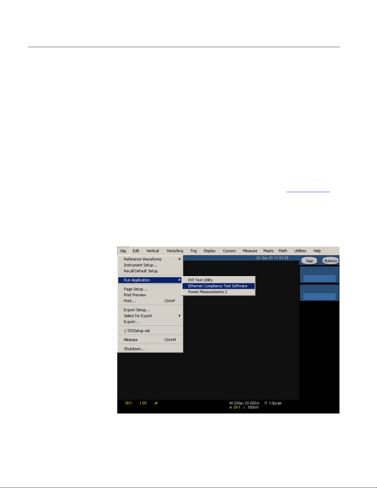
2-6
TDSET3 Printable Help Document
Getting Started
About the Test Fixture
The TF-GBE test fixture, designed by Tektronix and manufactured and
distributed by Crescent Heart Software, facilitates 1000BASE-T, 100BASE-TX
and 10BASE-T Ethernet compliance testing when used with an appropriate
supported oscilloscope and Tektronix TDSET3 Ethernet Compliance Test
Software. These fixtures are available from both C.H.S and Tektronix.
The TF-GBE-EE test fixture, designed, manufactured, and distributed by
Crescent Heart Software (C.H.S), facilitates 10BASE-Te Energy Efficient
Ethernet (EEE) compliance testing when used with an appropriate supported
oscilloscope and Tektronix TDSET3 Ethernet Compliance Test Software. The
fixture is available from C.H.S.
For more information, visit Crescent Heart Software Web site www.c-h-s.com
Starting the Application
1. From the oscilloscope menu, select File > Run Application > Ethernet
Compliance Test Software or Analyze > Ethernet Compliance Test Software.
.
Figure 2-1: Run application
Page 35
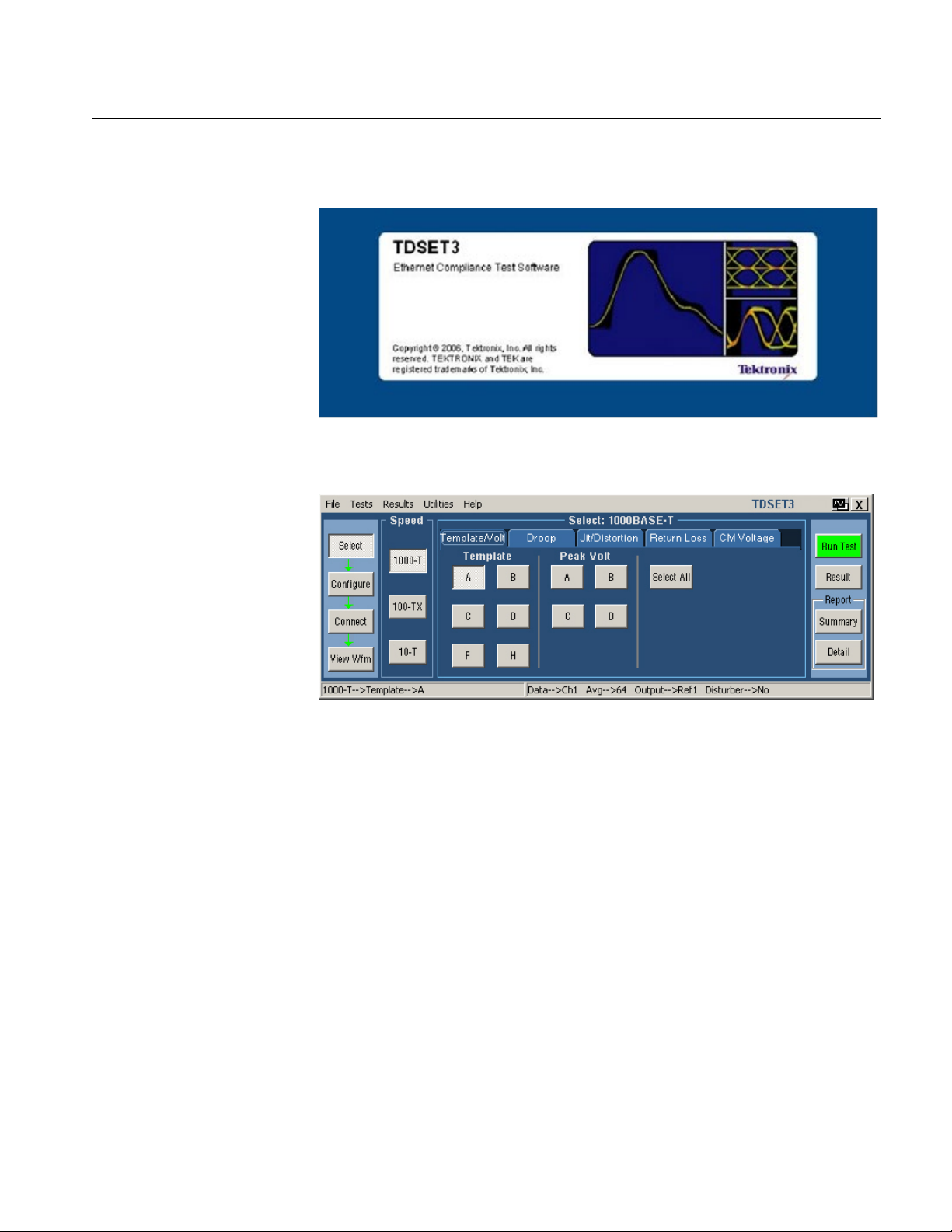
Getting Started
TDSET3 Printable Help Document
2-7
2. The splash screen appears.
3. The oscilloscope display resizes to fit the upper part of the screen and the
lower part of the oscilloscope screen displays the TDSET3 application.
Figure 2-2: Application interface
4. The application is automatically set to its default settings.
5. If you access oscilloscope functions, the oscilloscope display appears in full
screen and the TDSET3 application recedes to the background.
6. To return to the TDSET3 application, select the APP button in the
oscilloscope display.
Minimizing and Maximizing the Application
The application appears even when you minimize the oscilloscope.
To minimize the application, select File > Minimize. The TDSET3 window
minimizes to the Windows taskbar and upper half screen has the
oscilloscope display and lower half of the screen has the desktop
To maximize the application, select Ethernet Compliance Test Software in
the Windows taskbar
Page 36

2-8
TDSET3 Printable Help Document
Getting Started
To hide the application, select the Hide button or select File > Hide
The Report Generator module windows are independent of the TDSET3
application. Select the Minimize button on the right hand corner of the relevant
report generator window to minimize it
Note: If you select Hide button, the TDSET3 window goes to the background and
the oscilloscope display resizes to the whole screen.
Page 37

TDSET3 Printable Help Document
2-9
Returning to the Application
When you access oscilloscope functions, the oscilloscope fills the display. You
can access oscilloscope functions in the following ways:
Choose the Menu bar or the Toolbar mode on the oscilloscope and access
the menus
Press front-panel buttons
To return to the application, select the APP button on the top right of the
oscilloscope display
Getting Started
Exiting the Application
To exit the application, do the following:
Select File > Exit or select the Exit button
On exiting the application a message box "Do you want to restore the
oscilloscope settings to their state before starting this application?"
appears
Select Yes, No, or Cancel. Yes is selected by default
Note: Using other methods to exit the application results in abnormal
termination of the application.
Page 38

2-10
TDSET3 Printable Help Document
Table 2-2: Application default directories
Directory
Action
C:\TekApplications\TDSET3\Setup
Stores the application settings to
setup files.
C:\TekApplications\TDSET3\ReportGenerator\Templates
Stores the default templates of
report generator.
C:\TekApplications\TDSET3\ReportGenerator\Reports
Stores the Reports for 10BASE-T,
1000BASE-T.
1000BASE-T.
C:\TekApplications\TDSET3\AWGWaveforms
Stores the AWG/AFG waveforms.
C:\TekApplications\TDSET3\Images
Stores all the images.
Table 2-3: 1000BASE-T default layouts and templates
Test
Default template
1000BASE-T (Default layout — 1000T.rpl)
Coversheet for 1000BaseT_2.rgt
Template
1000T-TemplateA.rgt
1000T-TemplateH.rgt
1000T-PeakVoltD.rgt
Getting Started
Application Directories and File Names
The TDSET3 application uses directories to save and recall setup files and uses
file name extensions to identify the file type. The next table lists the default
directory names.
10BASE-Te, 100BASE-TX, and
C:\TekApplications\TDSET3\ReportGenerator\Layouts Stores the Report Layouts for
10BASE-T, 100BASE-TX, and
Application Software Default Layouts and Templates
Coversheet Coversheet for 1000BaseT.rgt
1000T-TemplateB.rgt
1000T-TemplateC.rgt
1000T-TemplateD.rgt
1000T-TemplateF.rgt
Peak Volt 1000T-PeakVoltA.rgt
1000T-PeakVoltB.rgt
1000T-PeakVoltC.rgt
Page 39

TDSET3 Printable Help Document
2-11
Table 2-3: 1000BASE-T default layouts and templates (cont)
Test
Default template
Droop
1000T-DroopG.rgt
1000T-DroopJ.rgt
Jitter
1000 Jitter Master filtered.rgt
1000T- Jitter slave unfiltered[TIE]_NOCLK.rgt
Distortion
1000T-Distortion.rgt
Common mode Voltage
1000T-Common mode Voltage.rgt
Return Loss
1000T-Return Loss.rgt
Table 2-4: 100BASE-TX default layouts and templates
Test
Default template
100BASE-TX (Default layout — 100TX.rpl)
Coversheet
Coversheet for 100BaseTX.rgt
Template
100-AOI Template.rgt
Differential Output Voltage
100-Differential Output Voltage.rgt
Signal Amplitude Symmetry
100-Signal Amplitude Symmetry.rgt
Rise Time
100-Rise Time.rgt
Fall Time
100-Fall Time.rgt
Rise/Fall Time Symmetry
100-Rise Fall Time Symmetry.rgt
Waveform Overshoot
100-Waveform Overshoot.rgt
Jitter
100-Transmit Jitter.rgt
Duty Cycle Distortion
100-Duty Cycle Distortion.rgt
Return Loss
100-Tx Return Loss.rgt
100-Rx Return Loss.rgt
Getting Started
1000 Jitter Master Unfiltered[TIE].rgt
1000 Jitter Master Unfiltered[HIS].rgt
1000 Jitter Slave filtered.rgt
1000 Jitter Slave Unfiltered[TIE].rgt
1000 Jitter Slave Unfiltered[HIS].rgt
1000T- Jitter master filtered_NOCLK.rgt
1000T- Jitter master unfiltered[HIS]_NOCLK.rgt
1000T- Jitter master unfiltered[TIE]_NOCLK.rgt
1000T- Jitter slave filtered_NOCLK.rgt
1000T- Jitter slave unfiltered[HIS]_NOCLK.rgt
Page 40

2-12
TDSET3 Printable Help Document
Table 2-5: 10BASE-T/10BASE-Te default layouts and templates
Test
Default template
10BASE-T/10BASE-Te (Default layout — 10T.rpl)
Coversheet
Coversheet for 10BaseT.rgt
Coversheet for 10BaseTe.rgt
MAU Ext Template
10 MAU ext template.rgt
MAU Ext Inv Template
10 mau ext inv template.rgt
MAU Int Template
10 mau int template.rgt
MAU Int Inv Template
10 mau int inv template.rgt
Link Pulse Template Load
10 Link Pulse Load1 with TPM template.rgt
10 Link Pulse 100 with TPM template.rgt
Link Pulse Template Load
10 Link Pulse Load1 without TPM template.rgt
10 Link Pulse 100 without TPM template.rgt
Link Pulse Timing
10 Link Pulse Timing.rgt
TP_IDL Template Load with
10 TP_IDL Load1 with TPM template.rgt
10 TP_IDL 100 with TPM template.rgt
TP_IDL Template Load
10 TP_IDL Load1 without TPM template.rgt
10 TP_IDL 100 without TPM template.rgt
Getting Started
with TPM
without TPM
TPM
without TPM
10 Link Pulse Load2 with TPM template.rgt
10 Link Pulse Load2 without TPM template.rgt
10 TP_IDL Load2 with TPM template.rgt
10 TP_IDL Load2 without TPM template.rgt
Page 41

TDSET3 Printable Help Document
2-13
Table 2-5: 10BASE-T/10BASE-Te default layouts and templates (cont)
Test
Default template
Differential Output Voltage
10 differential output voltage.rpt
Harmonic
10 harmonic of all ones.rgt
Jitter with cable Normal output
timing
10 output timing jitter with cable.rgt
Jitter with cable 8.0 output timing
10 8.0 output timing jitter with cable.rgt
Jitter with cable 8.5 output timing
10 8.5 output timing jitter with cable.rgt
Jitter without cable Normal output
timing
10 output timing jitter without cable.rgt
timing
Jitter without cable 8.5 output
timing
10 8.5 output timing jitter without cable.rgt
10 Rx Return Loss.rgt
Common mode Voltage
10 Common mode Voltage.rgt
Getting Started
Jitter without cable 8.0 output
Return Loss 10 Tx Return Loss.rgt
10 8.0 output timing jitter without cable.rgt
10e Common mode output voltage.rgt
Page 42

2-14
TDSET3 Printable Help Document
Table 2-6: Default settings
Parameter
Selection
Default setting
Speed
1000-T
Select > 1000-T
Template/Volt tab
Template/Volt tab
A Droop tab
G Jit/Distortion tab
Master Unfiltered
Return Loss tab
Return Loss
CM Voltage tab
CM Voltage
Select > 100-TX
Parametric tab
Parametric tab
Template (Both Polarity)
Return Loss tab
Transmitter
Configure > 1000-T
Data
CH1 Master CLK
CH2 Slave CLK
CH3
Data (TM2)
CH1 Data (TM3)
CH2
TX_TCLK
CH1
# Averages
64 Clock Edge
Rising
Hi Resolution
64
Output
Ref1 Disturbing Signal
No Filter
Int TX_TCLK
No LP Filter
Yes
Meas Type
TIE Probe:P1
CH1 Probe:P2
CH2 Pair ID
A Load
85, 100, 115 Ohm
Smooth
7
Record Length
Varies depending on the Memory option
available on the oscilloscope.
Hysteresis
5.00 %
Getting Started
Application Software Default Settings
The TDSET3 application is automatically set to the default settings. The next
table lists the default settings with which the TDSET3 application starts.
Page 43

Getting Started
TDSET3 Printable Help Document
2-15
Table 2-6: Default settings (cont)
Parameter
Selection
Default setting
Configure > 100-TX
Data
CH1
Mask Setup
Fail Threshold
1
Mask Scale
Normal
# Waveforms = 16
Pulse Width
16 ns
Probe:P1 / Probe:P3
CH1 Probe:P2 / Probe:P4
CH2 Load
85, 100, 115 Ohm
Smooth
7
# Averages
100 for Return Loss and 48 for other
tests
Configure > 10-T
Data
CH1
# Waveforms = 16
Section
Both MAU Type
Internal
MAU Scale
Normal
Fail Threshold
10 microseconds
Sequence
Normal (NLP)
Probe: P1 / Probe: P3
CH1 Probe: P2 / Probe: P4
CH2 Load
85, 100, 115 Ohm
Smooth
7 Energy Efficient
No
Report > Report Generator
Generate Report tab
Samples
Acquisition Sample/Average (depends on the
Acquisition Sample/Average (depends on the
Mask Setup
Samples
50K
parameter selected)
Average is the default mode
parameter selected)
Average is the default mode
50 K
1
Harmonic Ones
Output
# Averages
Time/Scale
Math1
48
Page 44

2-16
TDSET3 Printable Help Document
Getting Started
Page 45
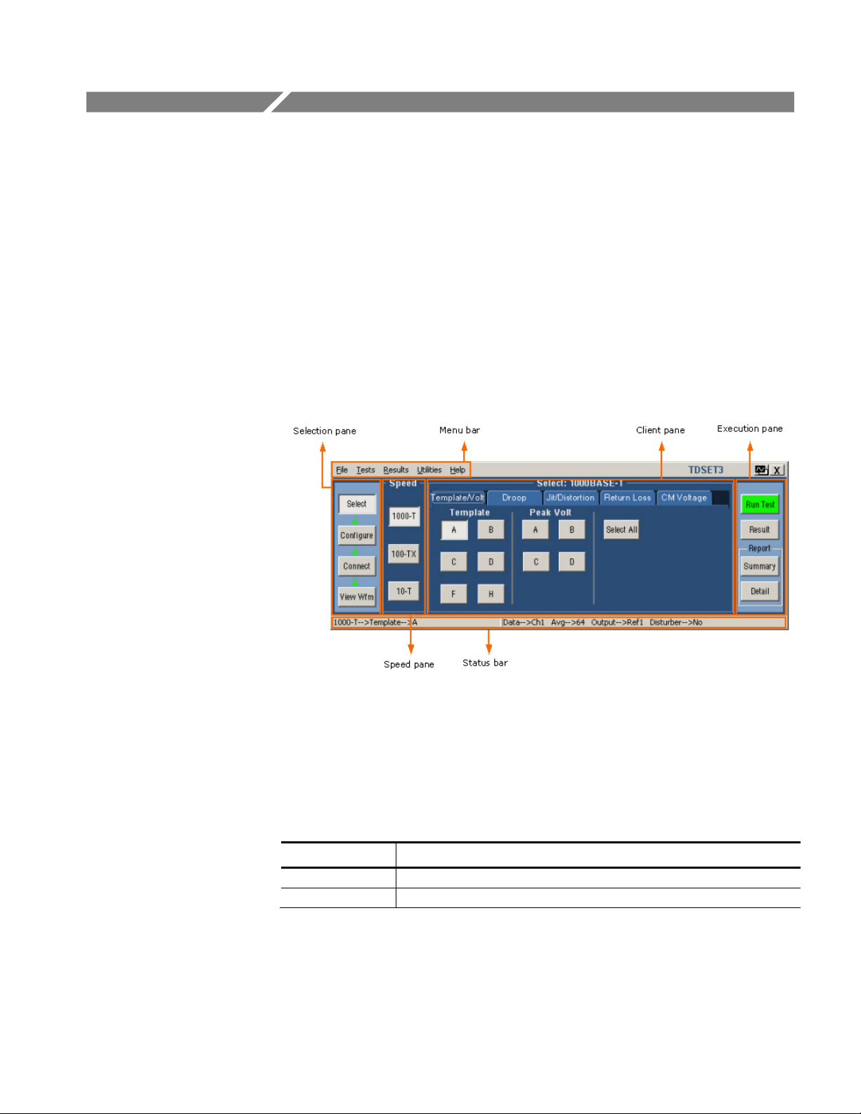
TDSET3 Printable Help Document
3-1
Table 3-1: Application interface controls
Controls
Description
Menu bar
Located at the top of the application and has the TDSET3 menus.
Tab
Labeled group of options with similar items.
Operating Basics
TDSET3 Application Window
The TDSET3 application is a Windows-based application. The application
window comprises the Menu bar, Selection pane, Speed pane, Client pane,
Execution pane, and Status bar. The Client pane changes between Configuration
pane, Parameter Selection pane, Connection pane, and View Waveform pane
depending on what you have selected in the Selection pane. The Client pane
changes to Result pane automatically after you run the test.
Figure 3-1: Application window
TDSET3 Application Interface Controls
The TDSET3 application interface uses the following controls:
Page 46

3-2
TDSET3 Printable Help Document
Table 3-1: Application interface controls (cont)
Controls
Description
Pane
Enclosed visual frame with a set of related options.
Option button
Defines a particular command or task.
Drop-down list box
Lists the items from which you can select one item.
Field
Box that you can use to type in text or to enter a value with the keypad or a
multipurpose knob.
Check Boxes
Square box that you can use to select or clear preferences.
Scroll bar
Vertical or horizontal bar at the side or bottom of a display area used to
move around that area.
Browse
Displays a window where you can look through a list of directories and files.
Command button
Initiates an immediate action.
Keypad
Appears when you select a box and enter a value.
oscilloscope to select a value.
Operating Basics
Menu bar
MP/GP knob Displays a line between the knob and the box. You can turn the knob on the
The menu bar of TDSET3 has the following menus.
File menu
Tests menu
Results menu
Utilities menu
Help menu
Page 47
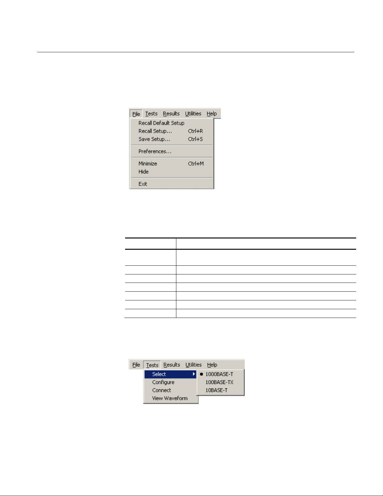
TDSET3 Printable Help Document
3-3
File Menu
Table 3-2: File menu
Menu selection
Description
Setup
Recall Setup
Recalls the application settings from a setup file.
Save Setup
Saves the application settings to a setup file.
Preferences
Shows/Hides the message boxes displayed while running the test.
Minimize
Minimizes the Application window.
Hide
Hides the Application window.
Exit
Displays the Restore Settings dialog box and closes the Application.
Operating Basics
The File menu appears as shown by the next figure:
Tests Menu
Figure 3-2: File menu
The next table lists the menu selection and description for the File menu:
Recall Default
Recalls the default settings for the application.
The Tests menu appears as shown by the next figure:
Figure 3-3: Tests menu
Page 48

3-4
TDSET3 Printable Help Document
Table 3-3: Tests menu
Menu selection
Description
Select
1000BASE-T
Displays the point and test parameter selections for 1000BASE-T in the
Client pane.
100BASE-TX
Displays the parameters for 100BASE-TX in the Client pane.
10BASE-T
Displays the parameters for 10BASE-T in the Client pane.
Configure
Displays the configuration details for the selected speed and test.
Connect
Displays the connection instructions for the selected speed.
View Waveform
Displays the waveform based on the settings.
Table 3-4: Results menu
Menu selection
Description
Summary
Displays the results summary of last test conducted.
Details
Displays the detailed results of last test conducted.
Operating Basics
The next table lists the menu selection and description for the Tests menu:
Results Menu
The Results menu appears as shown by the next figure:
Figure 3-4: Results menu
The next table lists the menu selection and description for the Results menu:
Utilities Menu
The Utilities menu appears as shown by the next figure:
Figure 3-5: Utilities menu
Page 49

TDSET3 Printable Help Document
3-5
Table 3-5: Utilities menu
Menu selection
Description
Report Generator
Displays the Report Generator window.
Enable Remote GPIB
Enables you to use remote GPIB commands to control the application.
Automate AWG/AFG
Enables you to automate file transfer and waveform setup on an
Arbitrary Waveform Generator/Arbitrary Function Generator.
Help Menu
Table 3-6: Help menu
Menu selection
Description
Help Topics
Displays the help file for the TDSET3 application.
Test Software
application.
Operating Basics
The next table lists the menu selection and description for the Utilities menu:
The Help menu appears as shown by the next figure:
Figure 3-6: Help menu
The next table lists the menu selection and description for the Help menu:
About Ethernet Compliance
Selection pane
The Selection pane located to the left of the Application window allows you to
navigate through the application.
Displays a dialog box with information about the current TDSET3
Figure 3-7: Selection pane
Page 50
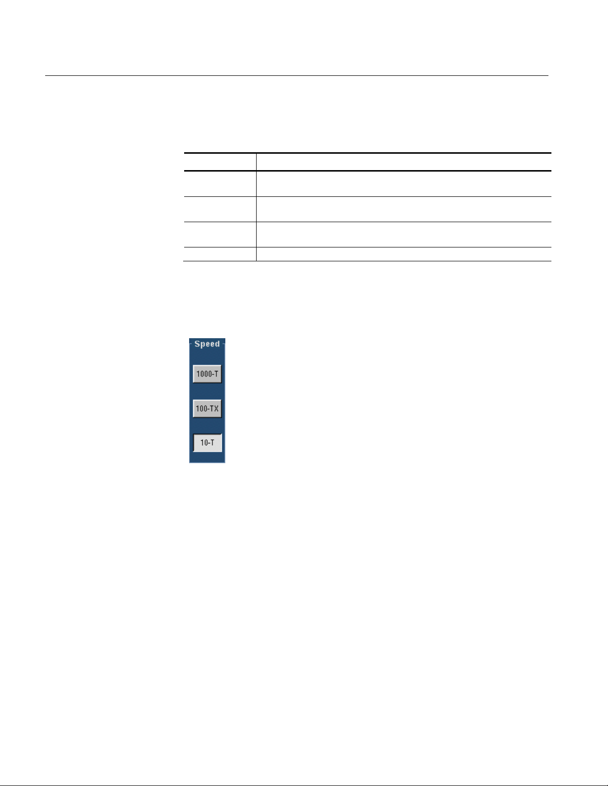
3-6
TDSET3 Printable Help Document
Table 3-7: Selection pane buttons
Button
Description
Select
Displays the test selection parameters in the Client pane for the selected
speed.
Configure
Displays the configuration parameters in the Client pane for the selected test
parameter.
parameter.
View Wfm
Displays the waveform in the Client pane for the selected test parameter.
Operating Basics
The next table lists the button and the task description:
Connect Displays the connection details in the Client pane for the selected test
Speed pane
The Speed pane located to the left of the application window displays the speed
to be selected.
Figure 3-8: Speed pane
Select 1000-T to test 1000BASE-T, 100-TX to test 100BASE-TX, and 10-T to
test 10BASE-T and 10BASE-Te.
The Client pane displays the parameters of the selected speed.
Page 51

TDSET3 Printable Help Document
3-7
Client pane
Operating Basics
The Client pane located adjacent to the Speed pane displays the test parameters,
configuration parameters, connections, view waveforms or results. Clicking on
each tab changes the Client pane to display the relevant test parameters.
1000BASE-T
Client pane
100BASE-TX
Client pane
The following figure shows the Client pane of
1000BASE-T Template:
Figure 3-9: 1000BASE-T Client pane
The following figure shows the Client pane of
100BASE-TX Template:
Figure 3-10: 100BASE-TX Client pane
Page 52
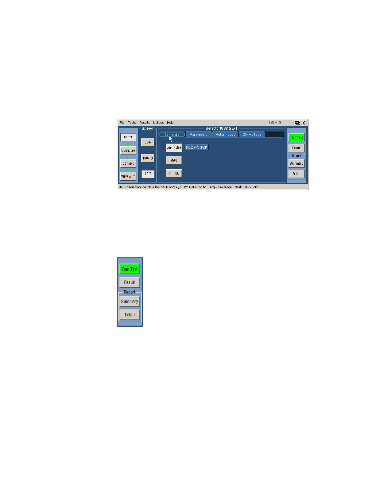
3-8
TDSET3 Printable Help Document
Operating Basics
10BASE-T/ 10BASE-Te Client pane
Figure 3-11: 10BASE-T Client pane
Execution pane
The Execution pane located to the right of the Application window displays the
buttons Run Test and Result.
The following figure shows the Client pane of
10BASE-T/10BASE-Te Template:
Figure 3-12: Execution pane
Page 53

Operating Basics
TDSET3 Printable Help Document
3-9
Table 3-8: Execution pane
Button
Button name
Description
Clicking on each button performs a particular task. The following table lists the
button and the task description:
Run Test Runs the selected test or tests.
Result Displays the Result pane that shows the test results.
Status bar
Report Summary
Report Detail
Displays the location to which the report summary is saved.
Click OK to store the result details in a .csv file.
Displays the location to which the detailed report is saved.
Click OK to store the result details in a .rpt file depending on
the layout selected in Report Configuration pane.
Note: The report details are real time and no history is maintained. Ensure that
you save the report details before you run another test.
At the bottom of the application window is the status bar that displays the
selected test and the important configuration parameters.
Figure 3-13: Status bar
Page 54

3-10
TDSET3 Printable Help Document
Operating Basics
Result pane
After you run a test, the Result pane automatically appears as shown by the
following figure:
Figure 3-14: Result pane for all tests
After you run a Return Loss test, the Result pane automatically appears as shown
by the following figure:
Figure 3-15: Result pane for Return Loss tests
The Result pane comprises Result Summary pane and Report Configuration
pane.
Page 55

TDSET3 Printable Help Document
3-11
Table 3-9: Result Summary pane buttons
Button
Description
Export
Exports the return loss values in a .csv file.
Clear Results
Clears the results in the Result Summary pane.
Pass/Fail/Inconclusive, and Remarks.
Template, 100BASE-TX Template or 10BASE-T Template.
waveform. This button is enabled only when you test Return Loss.
Operating Basics
Result
Summary
pane
The Result Summary pane displays the test results as Pass/Fail/Inconclusive.
Figure 3-16: Result Summary pane
Indicates that the test has passed.
Indicates that the test has failed.
Indicates that the test is inconclusive.
The next table lists the buttons and the task descriptions:
Result Details Displays the Result Details dialog box that shows the details of test results
categorized as Description, Specification range, Measured Value,
Manual Fit Displays the Manual Fit dialog box that allows you to adjust the waveform to
fit into the Mask. This button is enabled only when you test 1000BASE-T
Smooth Displays the Smooth dialog box that allows you to smoothen the return loss
Page 56

3-12
TDSET3 Printable Help Document
Table 3-10: Report Configuration fields
Field
Description
Device ID
To identify on which DUT the test was conducted by printing the Device ID
on the generated report.
Description on the generated report.
Pair ID
To identify the unique pairs by printing the Device Description on the
generated report. This field is enabled only for 1000BASE-T.
A default file name and path displayed for the selected speed.
Enable Preview
To automatically preview the report after generation and have the option to
save the report file.
Advanced button
Displays the Advanced Report Configuration dialog box.
Operating Basics
Report
Configuration
pane
You can set the report details to identify and
automatically generate the report. You can set a
default report file.
Figure 3-17: Report Configuration pane
The next table lists the report configuration fields and descriptions:
Device description To identify on which DUT the test was conducted by printing the Device
Report File To specify the path and the file in which the generated report will be saved.
Dialog Boxes
Preferences
dialog box
Use this dialog box to set the user preferences such as, show or hide the
Overwrite Reference message box, Overwrite Math message box, 10Base-T user
intervention for Template, 10Base-T user intervention for Jitter tests and
1000Base-T user intervention for Distortion test.
Page 57

TDSET3 Printable Help Document
3-13
Click File > Preferences to display the Preferences dialog box.
Table 3-11: Preferences
Show or Hide the
In Preference dialog box, select or clear the Show Ref overwrite check
Table 3-11: Preferences (cont)
Preference
Task description
Operating Basics
Figure 3-18: Preferences dialog box
The next table lists the preferences and task description:
Preference Task description
Overwrite
Reference
message box
box.
If you select Show Ref overwrite check box, the application displays the
following warning every time you run 1000BASE-T Template, Peak Volt,
Distortion, and Jitter tests. This dialog box also appears for Return Loss
tests. This dialog box appears for 1000BASE-T Droop test only if Disturbing
Signal is selected as Yes.
Page 58

3-14
TDSET3 Printable Help Document
Show or Hide the
In Preference dialog box, select or clear the Show Math overwrite check
automatically fit the waveform to mask.
Table 3-11: Preferences (cont)
Preference
Task description
Operating Basics
Overwrite Math
message box
Show or hide
10Base-T user
intervention for
Template tests
box.
If you select Show Math overwrite check box, the application displays the
following warning box every time you run 10BASE-T Harmonic Test.
In Preference dialog box, select or clear the Show 10Base-T Template
user control check box.
If you select the check box, the application displays the following warning
box every time you run 10BASE-T Template Test.
Toggle Lock Mask to Wfm between On and Off to lock or unlock the mask
to waveform when you zoom in or zoom out.
Toggle Mask Autofit between On and Off to allow the oscilloscope to
Page 59

Operating Basics
TDSET3 Printable Help Document
3-15
Show or hide
In Preference dialog box, select or clear the Show 1000Base-T Distortion
1000Base-T user
intervention for
Distortion test
user control check box.
If you select the check box, the application displays the following warning
box every time you run 1000BASE-T Distortion Test.
Page 60
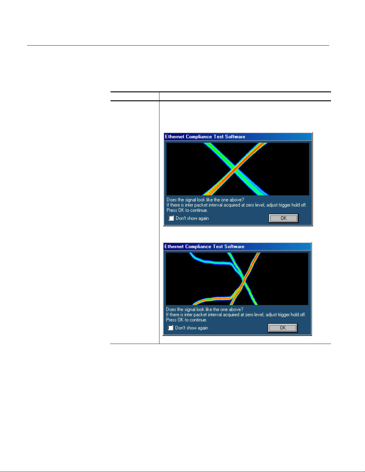
3-16
TDSET3 Printable Help Document
Table 3-11: Preferences (cont)
Preference
Task description
Show or hide
In Preference dialog box, select or clear the Show 10Base-T Jitter user
Operating Basics
10Base-T user
intervention for
Jitter tests
control check box.
If you select the check box, the application displays the following warning
box every time you run 10BASE-T Jitter with cable Test.
If you select the check box, the application displays the following warning
box every time you run 10BASE-T Jitter without cable Test.
Page 61
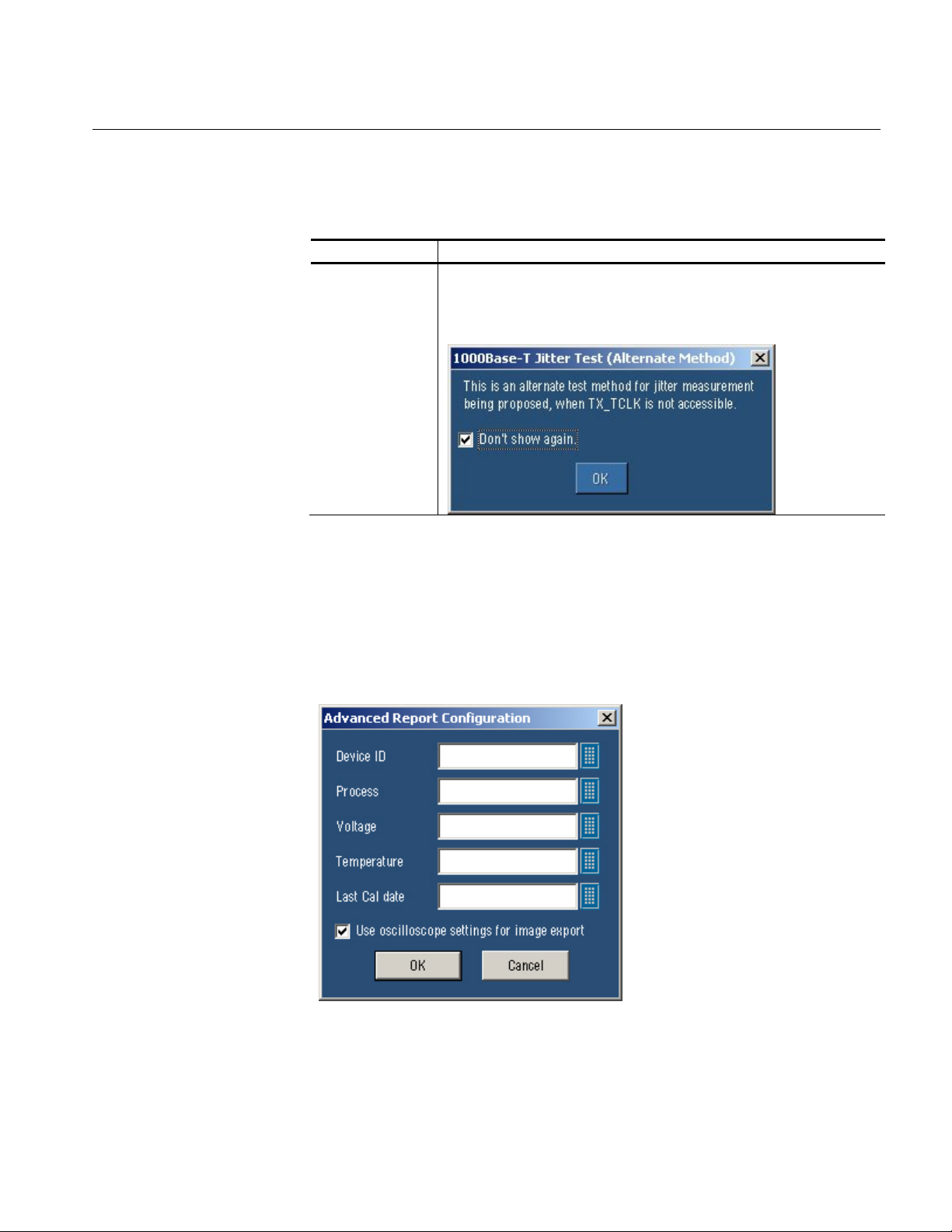
TDSET3 Printable Help Document
3-17
Table 3-11: Preferences (cont)
Preference
Task description
Show or Hide the
In Preference dialog box, select or clear the Show 1000Base-T Jitter
Operating Basics
Advanced
Report
Configuration
dialog box
message for
alternate
1000Base-T Jitter
test
message user control check box.
If you select the check box, the application displays the following message
every time you run 1000BASE-T JitterTest (Alternate Method).
Click OK to set the preferences.
Click Cancel to exit the Preference dialog box.
Select Results in the Execution pane, and Advanced in the Report Configuration
pane of the Result pane. The Advanced Report Configuration dialog box appears
as shown in the next figure:
Figure 3-19: Advanced Report Configuration dialog box
Page 62

3-18
TDSET3 Printable Help Document
Table 3-12: Advanced report configuration
Field
Description
Device ID
Prints the Device Id on the generated report to help you identify
on which DUT the test was conducted.
the process used for DUT.
the voltage values used while testing the DUT.
Temperature
Prints the Temperature on the generated report to help you
identify the temperature values used while making the DUT.
identify the date on which the oscilloscope was last calibrated.
Use oscilloscope settings for
image report
Select this check box to use the oscilloscope settings for
exporting images.
Operating Basics
The table lists the options that you can configure in the advanced report
configuration dialog box:
Process Prints the Process on the generated report to help you identify
Voltage Prints the Voltage on the generated report to help you identify
Last Cal date Prints the Last Cal date on the generated report to help you
Result Details
dialog box
Click OK to configure the report.
Click Cancel to exit the report setup.
Select Result Details button in Result pane to display the Result Details dialog
box.
After you have completed the test and you want to see the result details, click on
the Result Details button in Result pane. The Result Details dialog box appears
as shown by the following figure. The title bar displays the selected speed.
Figure 3-20: Result Details dialog box
Page 63

Operating Basics
TDSET3 Printable Help Document
3-19
Table 3-13: Result Details categorization
Category
Description
Description
Displays the selected test.
Spec Range
Displays the specification range.
Measured Value
Measured value of the selected test.
Pass/Fail
or .
Remarks
Additional information about the test.
The results are categorized as listed in the next table:
Test passed or failed or inconclusive as , ,
Note: Locate Hits, and Flash Hits are enabled only if a template test fails.
The TDS5000B series oscilloscopes do not support Flash Hits.
Locate Hits
dialog box
Select Locate Hits to view and change the mask color and hit color.
Select Flash Hits to flash the hits on the oscilloscope display.
Select Show Seg to display the mask segments.
Select Close to close the dialog box.
Note: If you run all the tests together using Select All, the Locate Hits, Flash
Hits, and Show Seg buttons are disabled.
Select Result Details button in Result pane to display the Result Details dialog
box. In the Result Details dialog box, select Locate Hits to display the Mask Hit
Locator dialog box as shown by the following figure:
Figure 3-21: Mask Segments dialog box
Page 64
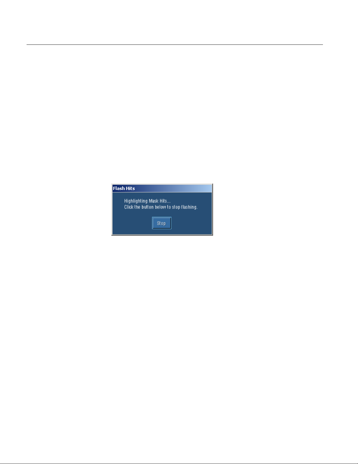
3-20
TDSET3 Printable Help Document
Operating Basics
1. Selecting Locate Hits changes the mask color and hit color. Closing the
Locate Hits dialog box will set the Mask color to default.
2. In the Circle Color drop-down list, select the color in which you want to see
the mask hits circled.
3. Select Save to save the mask-hit image as a jpg or a bmp file. The default
directory is C:\TekApplications\TDSET3\Images.
4. Select Close to close the dialog box.
Flash Hits
dialog box
Select Result Details button in Result pane to display the Result Details dialog
box. In the Result Details dialog box, select Flash Hits to flash the hits on the
oscilloscope display. The Flash Hits message box appears as shown by the
following figure:
Figure 3-22: Flash Hits message box
Select Stop in the Flash Hits message box to stop flashing the mask hits.
Page 65
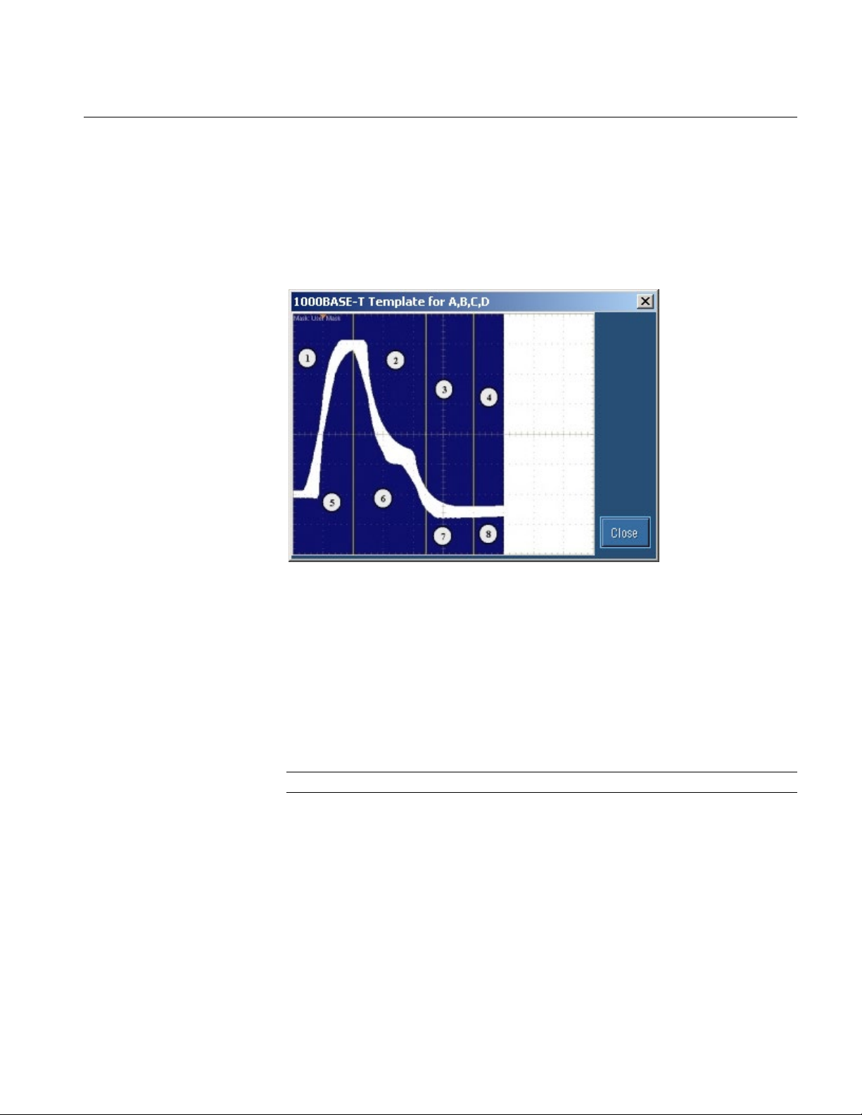
TDSET3 Printable Help Document
3-21
Operating Basics
Show
Segments
dialog box
Select Result Details button in Result pane to display the Result Details dialog
box. In the Result Details dialog box, select Show Seg to display the mask
segments. The Show Segments dialog box appears as shown by the following
figure:
Figure 3-23: Show Segments dialog box
Show Seg is enabled only if you run the template test.
Select Close to close the dialog box.
Manual Fit dialog box
Select Result Details button in Result pane to display the Result Details dialog
box. In the Result Details dialog box, select Manual Fit to display the manual fit
dialog box.
Note: If you select the Select All button, Manual Fit is not enabled.
Page 66

3-22
TDSET3 Printable Help Document
Operating Basics
If you are running 1000BASE-T Template test, the Manual Fit dialog box
appears as shown by the next figure:
Figure 3-24: 1000BASE-T Manual Fit dialog box
When you test Template in 1000BASE-T, you can manually fit the waveform
into the mask.
If the processed waveform does not lie within the mask, use Manual Fit to
manually fit the waveform into the mask as described below:
1. Click the arrow buttons to adjust the waveform to fit into the Mask.
2. Click OK to perform the mask pass/fail test again. Click Cancel to exit the
Manual Fit dialog box without performing the mask pass/fail test
If you are running 100BASE-TX or 10BASE-T Template tests, the Manual Fit
dialog box appears as shown by the next figure:
Figure 3-25: 100BASE-TX/10BASE-T Manual Fit dialog box
When you test Template in 100BASE-TX, and 10BASE-T, you can manually fit
the waveform into the mask.
Page 67

Operating Basics
TDSET3 Printable Help Document
3-23
If the processed waveform does not lie within the mask, use Manual Fit to
manually fit the waveform into the mask as follows:
1. To adjust the waveform to fit into the Mask, change the horizontal position
and vertical position using the general purpose knobs or Virtual Keyboard.
2. Click OK to perform the mask pass/fail test again.
Jig match
dialog box
If you are running 1000BASE-T Template test, the Jig Match button appears in
the Connect pane. Click Jig Match to display the Jig Match dialog box.
1000-T > Template > Connect > Jig Match
Note: Jig Match is enabled only if you select Disturbing Signal as Yes.
Figure 3-26: Jig Match dialog box for 1000-T Template/Peak Volt/Droop test
Page 68

3-24
TDSET3 Printable Help Document
Operating Basics
1000-T > Distortion > Connect > Jig Match
Figure 3-27: Jig Match dialog box for 1000-T Distortion test
Use Jig Match to effectively remove the disturbing signal and compensate for
non-linearities in the disturber and the test fixture. You can measure the
disturbing signal's Amplitude, and Frequency. You can also set the default
values. The application measures and displays the values in Measured Value
fields. You can validate the disturbing signal by comparing the Measured Value
with the Expected Value.
Page 69

TDSET3 Printable Help Document
3-25
To compensate for the Disturbing Signal, do the following:
1. Use TC5 of the test fixture for Disturber Compensation.
2. Make the connections as shown by the following figure:
Operating Basics
Figure 3-28: Connections for Disturber compensation
Note: Do not connect the Ethernet cable to J700 and the test port of the DUT.
3. Connect a BNC Cable to (AWG/AFG)+ and Channel 1 of Arbitrary
Waveform Generator/Arbitrary Function Generator.
4. Connect a BNC Cable to (AWG/AFG)– and Channel 2 (
) of Arbitrary
Waveform Generator/Arbitrary Function Generator.
5. Short the jumpers J621, J630, J620, J623, J721, J723, J680, and J781.
6. Connect the Differential Probe to P19 and configured channel of the
oscilloscope.
Page 70

3-26
TDSET3 Printable Help Document
Operating Basics
7. In the Jig Match dialog box, select Measure button in the Disturber
Compensation pane.
8. Compare the Measured Value with the Expected Value.
9. If the Measured Value is not approximately equal to the Expected Value,
modify the amplitude and clock frequency settings of the Arbitrary
Waveform Generator/Arbitrary Function Generator. Then click Measure and
compare the values to be approximately equal.
To compensate for the Test Fixture, do the following:
1. Use TC2 and TC5 of the test fixture for Test Fixture Compensation.
2. Make the connections as shown by the following figure:
Figure 3-29: Step 1 Connections of Test Fixture compensation
3. For Template, Droop, and Peak Voltage tests, set the DUT to generate Test
Mode 1 signal.
For Distortion test, set the DUT to generate Test Mode 4 signal.
Page 71

Operating Basics
TDSET3 Printable Help Document
3-27
4. Connect the Ethernet cable to J490 and the test port of the DUT.
5. Connect the Differential Probe to P9 and configured channel of the
oscilloscope.
6. In the Jig Match dialog box, select Measure button in Step 1 in the Test
Fixture Compensation pane.
7. Make the connections as shown by the following figure:
Figure 3-30: Step 2 Connections of Test Fixture compensation
8. For Template, Droop, and Peak Voltage tests, set the DUT to generate Test
Mode 1 signal.
For Distortion test, set the DUT to generate Test Mode 4 signal.
9. Connect the Ethernet cable to J700 and test port of the DUT.
10. Connect a BNC Cable to (AWG/AFG)+ and Channel 1 of Arbitrary
Waveform Generator/Arbitrary Function Generator.
11. Connect a BNC Cable to (AWG/AFG)- and Channel 2 (
) of Arbitrary
Waveform Generator/Arbitrary Function Generator.
12. Switch OFF the Arbitrary Waveform Generator/Arbitrary Function
Generator.
Page 72

3-28
TDSET3 Printable Help Document
Operating Basics
13. Short the jumpers J621, J630, J623, J721, J723, J680, and J781.
14. Connect the Differential Probe to P18 and configured channel of the
oscilloscope.
15. In the Jig Match dialog box, select Measure button in Step 2 in the Test
Fixture Compensation pane.
Virtual
Keyboard
dialog box
Selecting
Figure 3-31: Virtual keyboard
The field on the top displays what you have selected. After you have selected the
required number, select Enter.
adjacent to any number field displays the Virtual Keyboard.
Selecting Space inserts a space
Selecting Enter enters the value for the selected field
Selecting Backspace deletes the value entered
Selecting Esc exits the Virtual Keyboard
Page 73

TDSET3 Printable Help Document
3-29
Operating Basics
Virtual
Keypad
dialog box
Select the knob or the keypad icon adjacent to any text field to display the
Virtual Keypad dialog box.
Figure 3-32: Virtual keypad
Use this dialog box to enter custom values.
Selecting Set to min automatically displays the minimum value of the
selected field
Selecting Set to max automatically displays the maximum value of the
selected field
Selecting CLR clears the value for the field selected and returns to zero
value
Selecting Enter enters the value for the selected field
Page 74

3-30
TDSET3 Printable Help Document
Operating Basics
Mask Setup
dialog box
The Mask Setup button is available in the Configure pane and is enabled only
when you run template tests.
If you are configuring 100BASE-TX Template test, click on Mask Setup button
in the Configure pane to display the Mask Setup dialog box.
Figure 3-33: 100BASE-TX Mask Setup dialog box
In the Samples text box, enter the number of samples to use in the test. Entering
the number of samples stops the test when that number has been reached.
The accepted range of samples is between 5000 and 2,147,400,000. The default
number of samples is 16,000.
In the Fail Thresh text box, enter the minimum number of samples that must fail
for the test to fail.
The accepted range of samples is between 1 and 2,147,483,647. The default fail
threshold is 1.
Note: You can use the Virtual Keyboard or the General Purpose knobs to enter
the values in the Samples and Fail Thresh fields.
Page 75

Operating Basics
TDSET3 Printable Help Document
3-31
If you are configuring 10BASE-T Template test, click on Mask Setup button in
the Configure pane to display the Mask Setup dialog box.
Smooth
dialog box
Figure 3-34: 10BASE-T Mask Setup dialog box
In the # of Wfms text box, enter the number of waveforms to use in the test.
Entering the number of waveforms stops the test when that number has been
reached.
The accepted range of samples is between 1 and 2,147,483,647. The default
number of samples is 16.
In the Fail Thresh text box, enter the minimum number of samples that must fail
for the test to fail.
The accepted range of samples is between 1 and 2,147,483,647. The default fail
threshold is 1.
Select Result Details button in Result pane to display the Result Details dialog
box. In the Result Details dialog box, select Smooth to smoothen the return loss
waveform. This button is enabled only when you test Return Loss for all speeds.
Figure 3-35: Smooth dialog box
After you test Return Loss, you can change the smoothness of the waveform. The
accepted range is within 0 to 10. The default is 7.
Page 76
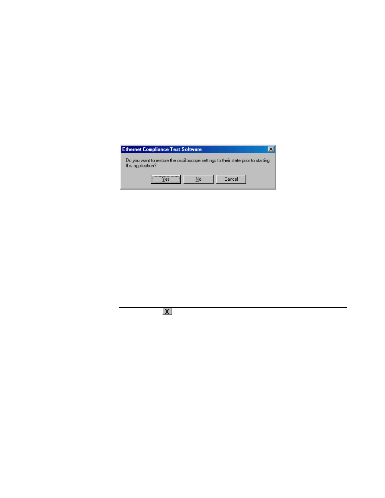
3-32
TDSET3 Printable Help Document
Operating Basics
Click the arrow buttons to increase or decrease the value and view the
smoothness of the waveform. The waveform is automatically updated as you
change the value.
Click Close to perform the pass/fail test again.
Exit
Select File > Exit to display the following message box:
dialog box
Figure 3-36: Exit dialog box
You can exit the application by restoring the oscilloscope settings to the previous
state before starting the application or retaining the present oscilloscope settings.
Select File> Exit
Select Yes to restore the oscilloscope settings to their original state before
starting the application and exit the application
or
Select No to retain the present oscilloscope settings and exit the application
or
Select Cancel to cancel the operation and return to the application
Note: Clicking
displays the Exit dialog box.
Page 77

TDSET3 Printable Help Document
4-1
Table 4-1: Select 1000BASE-T test parameters
Test parameter
Selection
1000BASE-T
Click Tests > Select > 1000BASE-T or select 1000-T in the
Speed pane.
Template
In the Template/Volt tab, select a point in the Template group.
Peak Voltage
In the Template/Volt tab, select a point in the Peak Volt group.
Droop
In the Droop tab, select a point.
Jitter Master Filtered
In the Jit/Distortion tab, select Master Filtered.
Jitter Master Unfiltered
In the Jit/Distortion tab, select Master Unfiltered.
Jitter Slave Filtered
In the Jit/Distortion tab, select Slave Filtered.
Jitter Slave Unfiltered
In the Jit/Distortion tab, select Slave Unfiltered.
Distortion
In the Jit/Distortion tab, select Distortion.
Return Loss
In the Return Loss tab, select Return Loss.
CM Voltage
In the CM Voltage tab, select CM Voltage.
How To Select Test Parameters
Selecting 1000BASE-T Test Parameters
The following table lists how to select the 1000BASE-T test parameters:
Note: The TDS5000B series oscilloscopes do not support Jitter Slave Filtered
test.
Page 78

4-2
TDSET3 Printable Help Document
Table 4-2: Select 100BASE-TX test parameters
Test parameter
Selection
100BASE-TX
Click Tests > Select > 100BASE-TX or select 100-TX in the Speed
pane.
Template
In the
tab, select Template. In the Polarity drop-down list,
For Both, the application tests all the segments.
Differential Output
Voltage
In the
tab, select Output Volt. In the Polarity drop-down list,
select Pos for positive, Neg for negative, or Both.
Symmetry
select Pos for positive, Neg for negative, or Both.
Rise Time
In the
tab, select Rise Time. In the Polarity drop-down list,
select Pos for positive, Neg for negative, or Both.
select Pos for positive, Neg for negative, or Both.
Rise/Fall Time
Symmetry
In the
tab, select R/F Sym. In the Polarity drop-down list,
select Pos for positive, Neg for negative, or Both.
select Pos for positive, Neg for negative, or Both.
Jitter
In the Parametric tab, select Jitter. In the Polarity drop-down list, select
Pos for positive, Neg for negative, or Both.
Select Random or 010101 in the Pattern drop-down list.
Return Loss
In the Return Loss tab, select either Transmitter or Receiver.
How To Select Test Parameters
Selecting 100BASE-TX Test Parameters
The following table lists how to select the 100BASE-TX test parameters:
select Pos for positive, Neg for negative, or Both.
For Positive polarity, the application tests segments 1, 2, 3, 6, and 7.
For Negative polarity, the application tests segments 4, 5, 8, 9, and 10.
Parametric
Parametric
Signal Amplitude
Fall Time In the Parametric tab, select Fall Time. In the Polarity drop-down list,
Waveform Overshoot In the Parametric tab, select Overshoot. In the Polarity drop-down list,
Duty Cycle Distortion In the Parametric tab, select Distortion.
In the Parametric tab, select Amp Sym. In the Polarity drop-down list,
Parametric
Parametric
Page 79

How To Select Test Parameters
TDSET3 Printable Help Document
4-3
Table 4-3: Select 10BASE-T/10BASE-Te test parameters
Test parameter
Selection
10BASE-T
Click Tests > Select > 10BASE-T or select 10-T in the Speed pane.
10BASE-T/
Template MAU
In the Template tab, select MAU and select Normal, Inverted or Both in
select the MAU Type as External or Internal.
TPM*.
10BASE-T/
In the Template tab, select TP_IDL. In the adjacent drop-down list, select
TPM*.
Differential Voltage
Harmonic
Select Normal, 8BT, 8.5BT, or All in the adjacent drop-down list.
10BASE-T Jitter
In the Parametric tab, select w/o Cable in Jitter group.
Select Normal, 8BT, 8.5BT, or All in the adjacent drop-down list.
10BASE-T Return
Loss
In the
tab, select either Transmitter or Receiver.
Voltage
* The loads 100 Ohm with TPM and 100 Ohm w/o TPM are optional and not required as per
the 802.3-2002 standards (for 10BASE-Te, refer to 802.3az standard).
Selecting 10BASE-T/10BASE-Te Test Parameters
The following table lists how to select the 10BASE-T test parameters:
10BASE-Te
10BASE-T Template
Link Pulse
10BASE-Te
Template TP_IDL
10BASE-T/
10BASE-Te
10BASE-T/
10BASE-Te
10BASE-T Jitter with
cable
without cable
10BASE-T CM
the adjacent drop-down list. Select Configure in the Selection pane and
In the Template tab, select Link Pulse. In the adjacent drop-down list,
select the load with or without TPM — Load1 w/o TPM, Load2 w/o TPM,
100 Ohm w/o TPM*, Load1 with TPM, Load2 with TPM, or 100 Ohm with
the load with or without TPM — Load1 w/o TPM, Load2 w/o TPM,
100 Ohm w/o TPM*, Load1 with TPM, Load2 with TPM, or 100 Ohm with
In the Parametric tab, select Diff Volt.
From the Peak drop-down list, select the peak value as Max or MinMax.
In the Parametric tab, select Harmonic.
In the Parametric tab, select With Cable in the Jitter group.
Return Loss
In the CM Voltage tab, select CM Voltage.
Page 80

4-4
TDSET3 Printable Help Document
How To Select Test Parameters
Page 81

TDSET3 Printable Help Document
5-1
How To Configure Parameters
Configuring 1000BASE-T
Use this dialog box to configure 1000BASE-T for Source, # Averages, Output,
Disturbing Signal, and Filter.
Figure 5-1: 1000BASE-T Configure pane
Page 82

5-2
TDSET3 Printable Help Document
How To Configure Parameters
The following table shows the 1000BASE-T tests parameters you can configure:
Table 5-1: 1000BASE-T Configure parameters
Page 83

TDSET3 Printable Help Document
5-3
Table 5-2: 1000BASE-T Configure parameter description
Configure parameters
Description
Source
The Data source and CLK source should be mutually exclusive. The Data source, Master
the TX_TCLK as Yes.
# of Averages
Clock Edge
Disturbing Signal
Select Yes or No depending on whether the disturbing signal is added to the test mode
Filter
TX_TCLK
Output
Select the reference waveform on which the processed waveform will be stored.
How To Configure Parameters
The following table describes the 1000BASE-T configuration parameters:
CLK source and Slave clock source should be mutually exclusive.
Data — Select the channel to which the DUT signal is connected.
Master CLK — Select the channel to which the master clock is connected.
Slave CLK — Select the channel to which the slave clock is connected.
TX_TCLK — Select the channel to which the TX_TCLK is connected.
Data (TM2) — Select the channel to which data in Test Mode 2 is connected.
Data (TM3) — Select the channel to which data in Test Mode 3 is connected.
Note: TX_TCLK drop-down list appears only for Distortion test and if you
have selected TX_TCLK as Yes.
Data (TM2) and Data (TM3) drop-down lists appear only for Jitter tests if you have selected
the TX_TCLK as No.
Master CLK and Slave CLK drop-down lists appear only for Jitter tests if you have selected
Enter the number of averages between 64 and 10000 depending on the noise present in
the acquired waveform.
Select the clock edge on which the oscilloscope finds the trigger point.
signal.
Select Int or Ext depending on whether the filter is applied internally or externally.
Select Yes or No to perform the Distortion test with TX_TCLK.
Page 84

5-4
TDSET3 Printable Help Document
Table 5-2: 1000BASE-T Configure parameter description (cont)
Configure parameters
Description
Meas Type
Select the measurement type as either Time Interval Error (TIE) or Histogram.
Hi Resolution
Enter the number of averages to be done in the vertical domain.
Return Loss
Probe: P1 and Probe: P2 — Select the channels to which the probes are connected.
Smooth — Enter the smoothening factor.
Hysteresis
How To Configure Parameters
Note: Depending on the Pair ID selected, the sources will change from
P1/P3/P5/P7 and P2/P4/P6/P8.
Load — Select the load as 85, 100, 115 Ohm or 100 Ohm.
Pair ID — Select the Pair ID as A, B, C, or D. Depending on the Pair ID selected the
sources will change from P1/P3/P5/P7 and P2/P4/P6/P8.
Return Loss — Select the reference waveform on which the output waveform will be
stored.
0 dB Marker — Select the reference waveform on which you want the 0 dB Marker to be
indicated.
Note: Return Loss and 0 dB Marker fields appear only if you set Load as
100 Ohm.
# Averages — Enter the number of waveforms you want to average.
Record Length
Low Pass Filter
Select the record length. This varies depending on the memory option available on the
oscilloscope.
Select Yes or No. The Low Pass Filter has a cutoff frequency of 150 MHz and when
applied, eliminates high frequency noise.
Enter the hysteresis percent value.
Page 85

How To Configure Parameters
TDSET3 Printable Help Document
5-5
Table 5-3: 1000BASE-T Configuration default settings
Parameter
Options
Default
Data
CH1, CH2, CH3, CH4
CH1
Master CLK
CH1, CH2, CH3, CH4
CH2
Slave CLK
CH1, CH2, CH3, CH4
CH3
Data (TM2)
CH1, CH2, CH3, CH4
CH1
Data (TM3)
CH1, CH2, CH3, CH4
CH2
# Averages
64 to 10000
64
Clock Edge
Rising, Falling
Rising
Disturbing Signal
Yes, No
No
Filter
Int, Ext
Int
TX_TCLK
No, Yes
No
TX_TCLK
CH1, CH2, CH3, CH4
CH2
Output
Ref1, Ref2, Ref3, Ref4
Ref1
Meas Type
Histogram, TIE
TIE
Hi Resolution
02 to 75
64
Probe:P1/P3/P5/P7
CH1, CH2, CH3, CH4
CH1
Probe:P2/P4/P6/P8
CH1, CH2, CH3, CH4
CH2
Pair ID
A, B, C, D
A
Load
85, 100, 115 or 100 Ohm
85, 100, 115 Ohm
Smooth
0 - 10
7
Record Length
Varies depending on the Memory option
available on the oscilloscope.
Low Pass Filter
Yes, No
Yes
Hysteresis
5.00% to 30.00%
5.00%
The following table lists the configuration parameters and default settings:
Note: The TDS5052B oscilloscope displays the graticule only for 100 Ohm
Load.
Page 86

5-6
TDSET3 Printable Help Document
How To Configure Parameters
Configuring 100BASE-TX
Use this dialog box to configure 100BASE-TX for Data source, Acquisition,
Rise/Fall Time Test, and Mask Setup.
Figure 5-2: 100BASE-TX Configure pane
The following table shows parameters of 100BASE-TX that you can configure:
Table 5-4: 100BASE-TX Configure parameters
Page 87

TDSET3 Printable Help Document
5-7
Table 5-5: 100BASE-TX Configure parameter description
Configure parameters
Description
Source
Select the channel to which the Device Under Test (DUT) is connected.
Acquisition
Rise/Fall Time Test
Select Pulse Width as 16 ns or 80 ns.
You can only configure this parameter for Rise/Fall Time Symmetry, Rise Time, and Fall
Mask Setup
You can configure the Samples and Fail Thresh. You can only configure these
How To Configure Parameters
The following table describes the 100BASE-TX configuration parameters:
Select Sample or Average depending on the acquisition mode.
The Acquisition is only enabled for some tests. If you select Average, enter the number
of waveforms in # of Wfms field.
If you select Sample, the application assumes the number of waveforms as 1.
You can use the virtual keyboard or the general-purpose knobs to enter the values in
the Sample and Average text boxes.
Mask Scale
Time tests.
Select Mask Scale as Normal, 0.95, or 1.05 depending on the Mask scale factor.
You can configure Mask Scale only for Template test.
parameters for the template tests.
Page 88

5-8
TDSET3 Printable Help Document
Table 5-5: 100BASE-TX Configure parameter description (cont)
Configure parameters
Smooth — Enter the smoothening factor.
Table 5-6: 100BASE-TX Configuration default settings
Parameter
Options
Default
Data
CH1, CH2, CH3, CH4
CH1
Acquisition
Sample, Average
If you select Sample, the default value is 1.
is 16.
Mask Scale
Normal, 0.95, 1.05
Normal
Sample and Fail Thresh.
Pulse Width
16 ns, 80 ns
80 ns
Probe:P1/P3
CH1, CH2, CH3, CH4
CH1
Probe:P2/P4
CH1, CH2, CH3, CH4
CH2
AWG/AFG
Select, AWG 4xx, AWG
AWG 7xxx, AFG 3xxx
Select
How To Configure Parameters
Return Loss
Probe: P1 and Probe: P2 — Select the channels to which the probes are connected on
the fixture.
Note: Depending on whether the Transmitter or Receiver is selected,
the source will change from P1/P3 and P2/P4.
Return Loss — Select the reference waveform on which the output waveform will be
stored.
0 dB Marker — Select the reference waveform on which you want the 0 dB Marker to
be indicated.
Note: Return Loss and 0 dB Marker fields appear only if you set Load
as 100 Ohm.
AWG/AFG Series — Select the AWG/AFG Series to use. If you select the default
value–Select–then the application considers all AWGs/AFGs other than the AWG 4xx
series.
Load — Select the load as 85, 100, 115 Ohm or 100 Ohm.
# Averages — Enter the number of waveforms you want to average.
The following table lists the configuration parameters and default settings:
Mask Setup See Mask Setup for information on default
If you select Average, the default # of Wfms
2021, AWG 5xx, AWG 6xx,
AWG 7xx, AWG 5xxx,
Page 89
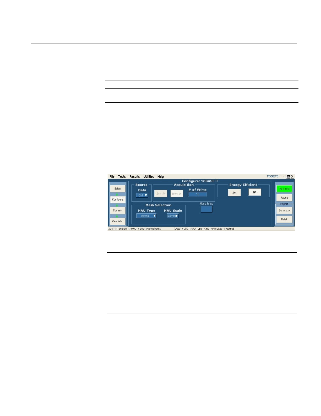
TDSET3 Printable Help Document
5-9
Table 5-6: 100BASE-TX Configuration default settings (cont)
Parameter
Options
Default
Load
85, 100, 115 Ohm or
100 Ohm
85, 100, 115 Ohm
Smooth
0 - 10
7
Note: The two-channel oscilloscopes display the graticule only for 100 Ohm
load.
Configuring 10BASE-T/10BASE-Te
How To Configure Parameters
Use this dialog box to configure 10BASE-T/10BASE-Te for Data source,
Acquisition, Harmonic Ones, and Mask Setup.
Figure 5-3: 10BASE-T/10BASE-Te Configure pane
Note: The 802.3az document includes the changes required to enable the Energy
Efficient Ethernet (EEE) operation for many existing physical layers. One of the
supported operations is twisted pair cabling. The PHY supports 100Base-TX,
1000Base T, 10Base-T, and other technologies. In addition to that EEE defines
reduced amplitude operation for 10Base-T which is called 10BASE-Te. All the
measurements of 100Base-TX and 1000Base T, and some of the measurements of
10Base-T are not affected when performing the 10BASE-Te measurements. The
10Base-T measurements that support the PHY tests for 10BASE-Te are modified
with a separate configuration to select and perform.
Page 90

5-10
TDSET3 Printable Help Document
Table 5-8: 10BASE-T/10BASE-Te Configure parameter description
Configure parameters
Description
Source
Acquisition
the Sample and Average text boxes.
How To Configure Parameters
The following table shows parameters of 10BASE-T/10BASE-Te to configure:
Table 5-7: 10BASE-T/10BASE-Te Configure parameters
The following table describes the 10BASE-T/10BASE-Te configuration
parameters:
Select the channel to which the Device Under Test (DUT) is connected.
Select Sample or Average depending on the acquisition mode. The Acquisition is only
enabled for some tests.
If you select Average, enter the number of waveforms in # of Wfms field.
If you select Sample, the application assumes the number of samples as 1.
You can use the virtual keyboard or the general-purpose knobs to enter the values in
Page 91

TDSET3 Printable Help Document
5-11
Table 5-8: 10BASE-T /10BASE-Te Configure parameter description (cont)
Configure parameters
Description
Mask Selection
Select MAU Type as Internal or External.
Mask Setup
You can configure the Samples and Fail Thresh. You can only configure these
Harmonic all of ones
Sequence
You can set the sequence to Normal (NLP) or Fast (FLP). You can only configure this
Test Options
Select Both to perform Template and Timing tests, Template Only to perform Template
tests, and Timing Only to perform Timing tests. Timing tests are available for normal link
How To Configure Parameters
Select MAU Scale as Normal, 0.9, or 1.1 depending on the MAU scale factor.
Select Section as Both, Head or Tail depending on the section of mask to test.
You can configure MAU Type and MAU Scale only for Template MAU tests.
You can configure Section only for Template TP_IDL and Link Pulse tests.
parameters for the template tests.
Select the math waveform on which the processed waveform will be displayed.
Enter the number of math waveforms to be averaged.
Enter the time or scale depending on the packet length being transmitted.
parameter for the Template Link Pulse test.
pulse.
Page 92
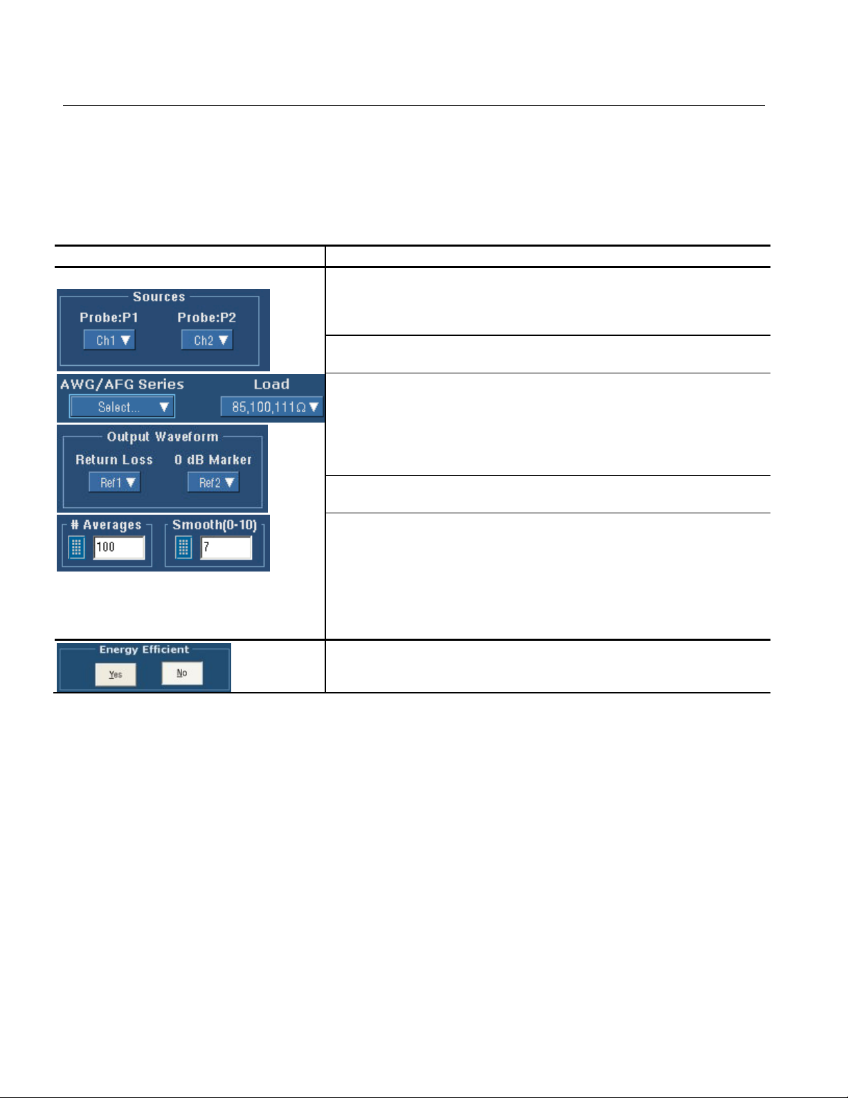
5-12
TDSET3 Printable Help Document
Table 5-8: 10BASE-T/10BASE-Te Configure parameter description (cont)
Configure parameters
Description
Return Loss
Probe: P1 and Probe: P2 — Select the channels to which the probes are connected on
Return Loss and 0dB Marker fields appear only if you set Load as
Smooth — Enter the smoothening factor.
Energy Efficient — Configure the test to run either in energy efficient mode or not.
How To Configure Parameters
the fixture.
Note: Depending on whether the Transmitter or Receiver is selected,
the source will change from P1/P3 and P2/P4.
Return Loss — Select the reference waveform on which the output waveform will be
stored.
0 dB Marker — Select the reference waveform on which you want the 0 dB Marker to
be indicated.
Note:
100 Ohm.
AWG/AFG Series — Select the AWG/AFG Series to use. If you select the default
value–Select–then the application considers all AWGs/AFGs other than the AWG 4xx
series.
Load — Select the load as 85, 100, 115 Ohm or 100 Ohm.
# Averages — Enter the number of waveforms you want to average.
Page 93

How To Configure Parameters
TDSET3 Printable Help Document
5-13
Table 5-9: 10BASE-T/10BASE-Te Configuration default settings
Parameter
Options
Default
Data
CH1, CH2, CH3, CH4
CH1
Acquisition
Sample, Average
If you select Sample, the default value is 1.
is 16.
Section
Both, Head, Tail
Both
MAU Type
Internal, External
Internal
MAU Scale
Normal, 0.9, 1.1
Normal
Sample and Fail Thresh.
Sequence
Normal (NLP), Fast (FLP)
Normal (NLP)
Test Options
Both, Template Only,
Timing Only
Both
Math4
Time/Scale
10 micro seconds, 1micro
seconds
10 micro seconds
# Averages
48 for other tests and 100 for Return Loss.
Probe:P1/P3
CH1, CH2, CH3, CH4
CH1
Probe:P2/P4
CH1, CH2, CH3, CH4
CH2
AWG 7xxx, AFG 3xxx
Load
85, 100, 115 Ohm or
100 Ohm
85, 100, 115 Ohm
Smooth
0 - 10
7
The following table lists the configuration parameters and default settings:
If you select Average, the default # of Wfms
Mask Setup See Mask Setup for information on default
Output Math1, Math2, Math3,
AWG/AFG Select, AWG 4xx, AWG
2021, AWG 5xx, AWG 6xx,
AWG 7xx, AWG 5xxx,
Math1
Select
Note: The TDS5052B oscilloscope displays the graticule only for 100 Ohm
Load.
Energy Efficient Yes, No No
Page 94

5-14
TDSET3 Printable Help Document
How To Configure Parameters
Page 95

TDSET3 Printable Help Document
6-1
Making Connections
1000BASE-T Connections
1000BASE-T
Template,
Peak Volt,
Droop, and
Distortion
Use TC5 of the test fixture for these tests with disturbing signal and TC2 of the
test fixture for these tests without disturbing signal.
With Disturbing Signal
Make the connections as shown by the following figure:
Figure 6-1: 1000BASE-T Connections with disturbing signal for Template, Peak Volt, Droop,
and Distortion
For Template, Peak Volt, and Droop tests, set the DUT to generate a Test Mode 1
signal. For Distortion test, set the DUT to generate Test Mode 4 signal.
Page 96

6-2
TDSET3 Printable Help Document
Making Connections
1. Connect the Ethernet cable to J700 and test port of the DUT.
2. Connect a BNC Cable to (AWG/AFG)+ and Channel 1 of Arbitrary
Waveform Generator/Arbitrary Function Generator.
3. Connect a BNC Cable to (AWG/AFG)− and Channel 2 (
Waveform Generator/Arbitrary Function Generator.
Note: The AWG/AFG waveforms are available in
C:\TekApplications\TDSET3\AWGWaveforms. You can use relevant waveform
files to generate the disturbing signal. Some of the AWG/AFG models do not
support the .set file for automatic settings. Refer to the ReadMe.txt file for
instructions to make those settings manually. In particular, ensure that the
AWG/AFG clock frequency is set to 250 MHz. This file is available in the
corresponding AWG waveform file folder. You can automate the AWG/AFG to
transfer files and settings as described in Automate AWG/AFG.
4. To test Pair A, do the following:
) of Arbitrary
Short the jumpers J621, J630, J623, J721, J723, J680, and J781
Ensure that the other jumpers are open
Connect the Differential Probe to P18 and configured channel of the
oscilloscope
5. To test Pair B, do the following:
Short the jumpers J620, J622, J631, J721, J723, J680, and J781
Ensure that the other jumpers are open
Connect the Differential Probe to P18 and configured channel of the
oscilloscope
6. To test Pair C, do the following:
Short the jumpers J620, J623, J720, J730, J723, J680, and J781
Ensure that the other jumpers are open
Connect the Differential Probe to P18 and configured channel of the
oscilloscope
Page 97

Making Connections
TDSET3 Printable Help Document
6-3
7. To test Pair D, do the following:
Short the jumpers J620, J623, J721, J722, J731, J680, and J781
Ensure that the other jumpers are open
Connect the Differential Probe to P18 and configured channel of the
oscilloscope
Without Disturbing Signal
Make the connections as shown by the following figure:
Figure 6-2: 1000BASE-T Connections without disturbing signal for Template, Peak Volt,
Droop, and Distortion
1. For Template, Peak Volt, and Droop tests, set the DUT to generate a Test
Mode 1 signal.
For Distortion test, set the DUT to generate a Test Mode 4 signal.
Page 98

6-4
TDSET3 Printable Help Document
Making Connections
2. Connect the Ethernet cable to J490 and test port of the DUT.
3. To test Pair A, connect the Differential Probe to P9 and configured channel
of the oscilloscope.
4. To test Pair B, connect the Differential Probe to P10 and configured channel
of the oscilloscope.
5. To test Pair C, connect the Differential Probe to P11 and configured channel
of the oscilloscope.
6. To test Pair D, connect the Differential Probe to P12 and configured channel
of the oscilloscope.
Note: Align the positive (+) probe-tip of the differential probe with the notch
marked on the test fixture.
Page 99

TDSET3 Printable Help Document
6-5
Making Connections
1000BASE-T
Jitter Master
Filtered
If you have access to TX_TCLK
Step 1
Use TC3 of the test fixture to calculate master clock jitter. Make the connections
as shown by the following figure:
Figure 6-3: 1000BASE-T Step 1 Connections for Jitter Master Filtered
1. Set the DUT in Normal mode as Master.
2. Connect the Ethernet cable to J501 and test port of the DUT.
3. Connect the Test Channel spool to J580 and Link partner.
4. Connect the active probe from TX_TCLK of the DUT to the configured
channel of the oscilloscope.
5. To test Pair A, connect the Differential Probe to P13 and configured channel
of the oscilloscope.
Page 100

6-6
TDSET3 Printable Help Document
Making Connections
6. To test Pair B, connect the Differential Probe to P14 and configured channel
of the oscilloscope.
7. To test Pair C, connect the Differential Probe to P15 and configured channel
of the oscilloscope.
8. To test Pair D, connect the Differential Probe to P16 and configured channel
of the oscilloscope.
 Loading...