

Page 1

Getting Started with TDSET2
Y ou can use this side of the Quick Reference to get started
with testing the Ethernet’s physical layer for 1000Base--T
Templates. The other side contains a complete menu tree for
the TDSET2 application.
NOTE. For complete operating instructions,
refer to the Online Help for the application.
TDSET2 Ethernet Compliance Test Software coupled with
TDS7000, CSA7000 and TDS6000 Series oscilloscopes,
enhances efficiency with faster validation cycles and much
higher reliability.
Testing 1000Base--T Templates
Follow these steps:
1. Connect the probes to the Device Under Test (DUT).
For example, the test setup for 1000Base--T Template is
shown below.
NOTE. You can also select one template at a
time to test.
5. Select the Configure toggle button in the Control pane
to change the configuration settings.
6. Select the data source and set the reference waveform on
which the processed waveform will be stored.
7. To test Templates with disturbing signal, select
Disturbing Signal as Yes and assign trigger and clock
channels.
NOTE. If you want to test Templates without
disturbing signal, select Disturbing Signal as
No and skip step 8 to 12.
8. Measure and compensate the disturbance of the test
fixture using Jig Match.
12. Connect the DUT signal at probing point with Port1
connected to 100 ohm termination and measure
attenuation.
13. Select Report Setup to configure the report setup to
identify and automatically preview the report.
14. Select Run Test in the Control pane. The application
displays the resulting waveform and the results as pass
or fail in the Result Summary pane as shown below.
2. Select File> Run Application> Ethernet Compliance
Software in the oscilloscope menu bar.
3. Select 1000 --T in the Speed pane.
4. In the Template/Volt tab, click Select All.
For up-to-date information on Tektronix oscilloscope
solutions for Ethernet Compliance Test, access the
www.tektronix.com
TDSET2 Ordering Information
(Supports the TDS6000, TDS7000, CSA7000 Series of
oscilloscopes. Refer to the Optional Applications Software
on Windows-Based Oscilloscopes Installation Manual for a
list of specific models. The applications CD includes a PDF
file of the installation manual.)
web page.
9. Connect the disturbing signal at Port1 and measure
amplitude and frequency across PortS with 100ohm
termination.
10. Connect the CLK signal across 100 ohm termination
and measure phase difference with respect to disturbing
signal.
11. Click Next in Jig Match dialog box, connect the DUT
signal at PortS with Port1 connected to 100 ohm
termination and measure amplitude.
If you order Option ET2 along with
TDS6000/TDS7000/CSA7000
H Ethernet Compliance Test Software is installed and
enabled
To order an upgrade for an existing oscilloscope:
H Order TDS6UP -- Opt. ET2
H Order TDS7UP -- Opt. ET2
H Order CSA7UP -- Opt. ET2
Recommended Accessories
H Opt. 2M for TDS7000/CSA7000
NOTE. To manually fit the waveform into the
mask, select Manual Fit in the Control pane.
You can manually fit only one waveform at a
time into the mask.
15. Select Result Details in the Control pane for more
information.
16. To generate a report automatically, select Report in the
Control pane.
17. If you want to customize the report format, select
Report> Report Generator. In the Generate Report tab,
select the template and select the Generate button to post
the test data to the template.
TDSET2
Ethernet Compliance Test Software
Reference
www.tektronix.com
*P071126000*
071-1260-00
Page 2
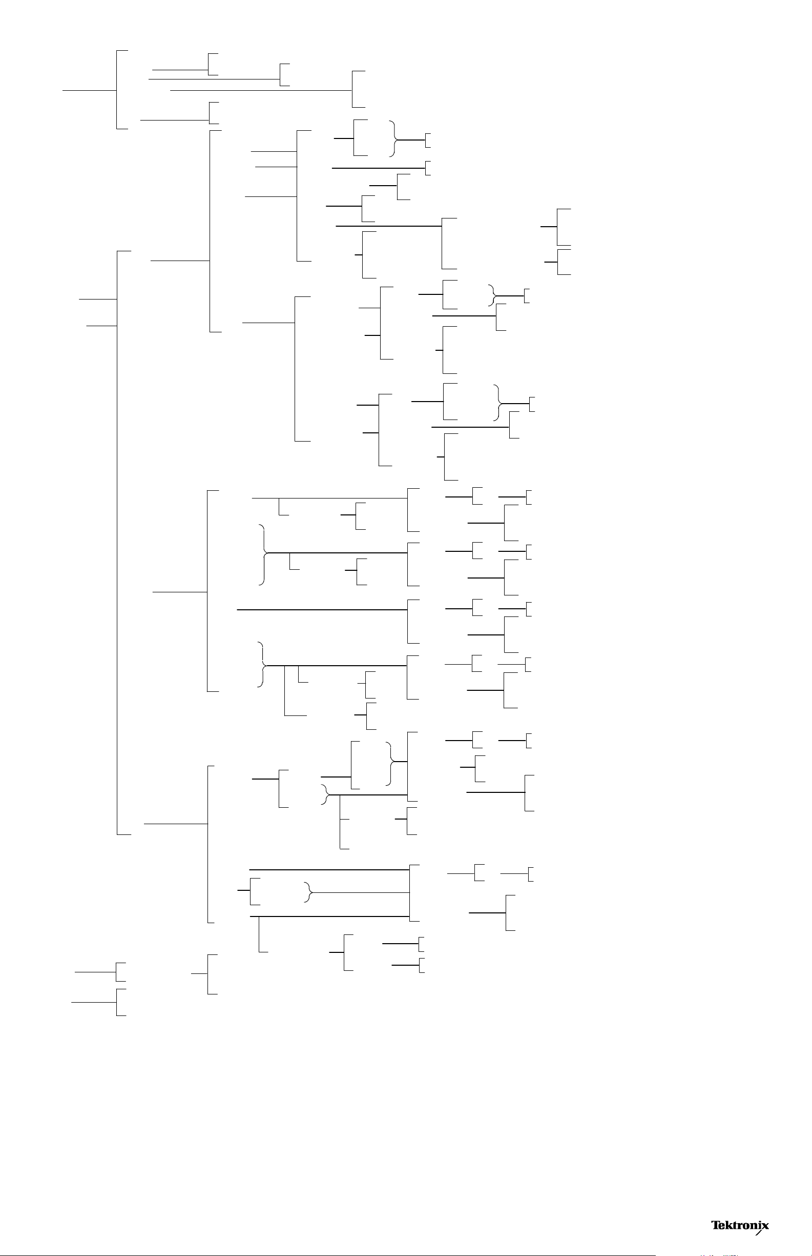
TDSET2 Menu Tree
File
Recall Default
Recall
Save
Preferences
Minimize
Hide
Exit
1000--T
File Browser
Open | Cancel
Restore Oscilloscope Settings
Yes | No| Cancel
Templa te
Peak Volt
Droop
File Browser
Save | Cancel
Source
# Averages
Output
Disturbing Signal
Filter
JigMatch
Report Setup
Show Ref Overwrite
Show Math Overwrite
Show 100TX: DCD Option
Data
Trigger
CLK
Int
Ext
Device ID
Device Description
Pair ID
Report File
Ch1 | Ch2 | Ch3 | Ch4 | None
Ref1 | Ref2 | Ref3 | Ref4
Yes
No
Disturber Compensation
Test Fixture Compensation
Amp
Freq
Phase
Amp
Atten
Select
Configure
100--TX
Jitter
Templa te
Output Volt
Amp Sym
Distortion
Overshoot
Jitter
Rise Time
Fall Time
R/F Sym
Master Filtered
Master Unfiltered
Slave Filtered
Slave Unfiltered
Mask Setup
Acquisition
Pulse Width
Acquisition
Source
Clock Edge
Report Setup
Source
Clock Edge
Report Setup
Samples
Fail Thresh
Sample
Average
16ns
80ns
Sample
Average
Data
Master CLK
Device ID
Device Description
Pair ID
Report File
Data
Master CLK
Slave CLK
Device ID
Device Description
Pair ID
Report File
Source
Report Setup
Source
Report Setup
Source
Report Setup
Source
Report Setup
Data
Data
Data
Data
Ch1 | Ch2 | Ch3 | Ch4 | None
Rising
Falling
Ch1 | Ch2 | Ch3 | Ch4 | None
Rising
Falling
Ch1 | Ch2 | Ch3 | Ch4
Device ID
Device Description
Report File
Ch1 | Ch2 | Ch3 | Ch4
Device ID
Device Description
Report File
Ch1 | Ch2 | Ch3 | Ch4
Device ID
Device Description
Report File
Ch1 | Ch2 | Ch3 | Ch4
Device ID
Device Description
Report File
Report
Help
Templa te
10--T
Diff Volt
Jitter
Harmonic
Report Generator
Help Topics
About Ethernet Compliance Test Software
De fin e Test Template
Define Report Layout
Generate Report
MAU Test
TP_IDL
Link Pulse
with Cable
without Cable
Harmonic Ones
Ext
Ext Inv
Int
Int Inv
Acquisition
Load 1w/TPM, Load2w/TPM, Load3w/TPM, Load1w/oTPM, Load2w/oTPM, Load3w/oTPM
Output
# Averages
Time/Scale
Source
Mask Setup
Report Setup
Sample
Average
Source
Report Setup
Math1 | Math2 | Math3 | Math4
10 microseconds or 1 microsecond
Data
Samples
Fail Thresh
Data
Ch1 | Ch2 | Ch3 | Ch4
Device ID
Device Description
Report File
Ch1 | Ch2 | Ch3 | Ch4
Device ID
Device Description
Report File
Copyright Tektronix, Inc.
 Loading...