

Page 1

User Manual
TDSCPM1
Communications Pulse Measurements Application
071-0605-00
This document supports software version 1.0.0
and above.
Warning
The servicing instructions are for use by
qualified personnel only. To avoid personal
injury, do not perform any servicing unless you
are qualified to do so. Refer to all safety
summaries prior to performing service.
Page 2

Copyright © Tektronix, Inc. All rights reserved. Licensed software products are owned by Tektronix or its suppliers and
are protected by United States copyright laws and international treaty provisions.
Use, duplication, or disclosure by the Government is subject to restrictions as set forth in subparagraph (c)(1)(ii) of the
Rights in T echnical Data and Computer Software clause at DFARS 252.227-7013, or subparagraphs (c)(1) and (2) of the
Commercial Computer Software – Restricted Rights clause at F AR 52.227-19, as applicable.
T ektronix products are covered by U.S. and foreign patents, issued and pending. Information in this publication supercedes
that in all previously published material. Specifications and price change privileges reserved.
T ektronix, Inc., P.O. Box 1000, Wilsonville, OR 97070–1000
TEKTRONIX and TEK are registered trademarks of T ektronix, Inc.
Page 3

WARRANTY
T ektronix warrants that the media on which this software product is furnished and the encoding of the programs on the media
will be free from defects in materials and workmanship for a period of three (3) months from the date of shipment. If a
medium or encoding proves defective during the warranty period, T ektronix will provide a replacement in exchange for the
defective medium. Except as to the media on which this software product is furnished, this software product is provided “as
is” without warranty of any kind, either express or implied. T ektronix does not warrant that the functions contained in this
software product will meet Customer’s requirements or that the operation of the programs will be uninterrupted or error-free.
In order to obtain service under this warranty, Customer must notify Tektronix of the defect before the expiration of the
warranty period. If T ektronix is unable to provide a replacement that is free from defects in materials and workmanship
within a reasonable time thereafter, Customer may terminate the license for this software product and return this software
product and any associated materials for credit or refund.
THIS WARRANTY IS GIVEN BY TEKTRONIX IN LIEU OF ANY OTHER WARRANTIES, EXPRESS OR
IMPLIED. TEKTRONIX AND ITS VENDORS DISCLAIM ANY IMPLIED WARRANTIES OF
MERCHANTABILITY OR FITNESS FOR A PARTICULAR PURPOSE. TEKTRONIX’ RESPONSIBILITY TO
REPLACE DEFECTIVE MEDIA OR REFUND CUSTOMER’S PAYMENT IS THE SOLE AND EXCLUSIVE
REMEDY PROVIDED TO THE CUSTOMER FOR BREACH OF THIS WARRANTY. TEKTRONIX AND ITS
VENDORS WILL NOT BE LIABLE FOR ANY INDIRECT , SPECIAL, INCIDENTAL, OR CONSEQUENTIAL
DAMAGES IRRESPECTIVE OF WHETHER TEKTRONIX OR THE VENDOR HAS ADVANCE NOTICE OF
THE POSSIBILITY OF SUCH DAMAGES.
Page 4

Page 5

Table of Contents
Getting Started
Operating Basics
General Safety Summary
Preface
Related Documentation vii. . . . . . . . . . . . . . . . . . . . . . . . . . . . . . . . . . . . . . . . . . . .
Conventions viii. . . . . . . . . . . . . . . . . . . . . . . . . . . . . . . . . . . . . . . . . . . . . . . . . . . . .
Contacting T ektronix viii. . . . . . . . . . . . . . . . . . . . . . . . . . . . . . . . . . . . . . . . . . . . . .
Product Description 1. . . . . . . . . . . . . . . . . . . . . . . . . . . . . . . . . . . . . . . . .
Compatibility 1. . . . . . . . . . . . . . . . . . . . . . . . . . . . . . . . . . . . . . . . . . . . . . . . . . . .
Requirements and Restrictions 2. . . . . . . . . . . . . . . . . . . . . . . . . . . . . . . . . . . . . . .
Updates Through a Web Browser 2. . . . . . . . . . . . . . . . . . . . . . . . . . . . . . . . . . . .
Optional Accessories 2. . . . . . . . . . . . . . . . . . . . . . . . . . . . . . . . . . . . . . . . . . . . . .
Accessories 2. . . . . . . . . . . . . . . . . . . . . . . . . . . . . . . . . . . . . . . . . . . . . . . . . . . . . .
Installation 3. . . . . . . . . . . . . . . . . . . . . . . . . . . . . . . . . . . . . . . . . . . . . . . .
Installing the Application 3. . . . . . . . . . . . . . . . . . . . . . . . . . . . . . . . . . . . . . . . . . .
Connecting to a System Under T est 4. . . . . . . . . . . . . . . . . . . . . . . . . . . . . . . . . . .
Operating Basics 5. . . . . . . . . . . . . . . . . . . . . . . . . . . . . . . . . . . . . . . . . . .
Application Menu Structure 5. . . . . . . . . . . . . . . . . . . . . . . . . . . . . . . . . . . . . . . . .
Main and Side Menus 5. . . . . . . . . . . . . . . . . . . . . . . . . . . . . . . . . . . . . . . . . .
Common Menu Items 6. . . . . . . . . . . . . . . . . . . . . . . . . . . . . . . . . . . . . . . . . .
Utility Menus 6. . . . . . . . . . . . . . . . . . . . . . . . . . . . . . . . . . . . . . . . . . . . . . . .
Using Basic Oscilloscope Functions 6. . . . . . . . . . . . . . . . . . . . . . . . . . . . . . . . . .
Using Local Help 6. . . . . . . . . . . . . . . . . . . . . . . . . . . . . . . . . . . . . . . . . . . . .
Returning to the Application 7. . . . . . . . . . . . . . . . . . . . . . . . . . . . . . . . . . . . .
Configuring the Display 7. . . . . . . . . . . . . . . . . . . . . . . . . . . . . . . . . . . . . . . . . . . .
Setting Up the Application 8. . . . . . . . . . . . . . . . . . . . . . . . . . . . . . . . . . . . . . . . . .
Communications Standards 8. . . . . . . . . . . . . . . . . . . . . . . . . . . . . . . . . . . . .
Data Rates 8. . . . . . . . . . . . . . . . . . . . . . . . . . . . . . . . . . . . . . . . . . . . . . . . . . .
T ests 10. . . . . . . . . . . . . . . . . . . . . . . . . . . . . . . . . . . . . . . . . . . . . . . . . . . . . . .
Setup Parameters 11. . . . . . . . . . . . . . . . . . . . . . . . . . . . . . . . . . . . . . . . . . . . . .
ITU-T G.703 Data Rates and Selections 11. . . . . . . . . . . . . . . . . . . . . . . . . . . .
ANSI T1.102 Data Rates and Selections 13. . . . . . . . . . . . . . . . . . . . . . . . . . .
T aking Measurements 14. . . . . . . . . . . . . . . . . . . . . . . . . . . . . . . . . . . . . . . . . . . . .
Saving the Results to a Data Log File 15. . . . . . . . . . . . . . . . . . . . . . . . . . . . . . . . .
Data Log File Format 15. . . . . . . . . . . . . . . . . . . . . . . . . . . . . . . . . . . . . . . . . .
Importing a Data Log File to a Personal Computer 16. . . . . . . . . . . . . . . . . . . . . . .
Viewing Data 16. . . . . . . . . . . . . . . . . . . . . . . . . . . . . . . . . . . . . . . . . . . . . . . . . . . .
Saving and Recalling Setups 18. . . . . . . . . . . . . . . . . . . . . . . . . . . . . . . . . . . . . . . .
Saving a Setup 18. . . . . . . . . . . . . . . . . . . . . . . . . . . . . . . . . . . . . . . . . . . . . . . .
Recalling a Setup 19. . . . . . . . . . . . . . . . . . . . . . . . . . . . . . . . . . . . . . . . . . . . .
Exiting the Application 19. . . . . . . . . . . . . . . . . . . . . . . . . . . . . . . . . . . . . . . . . . . .
Tutorial 21. . . . . . . . . . . . . . . . . . . . . . . . . . . . . . . . . . . . . . . . . . . . . . . . . . .
Connecting to a Communications Signal 21. . . . . . . . . . . . . . . . . . . . . . . . . . . . . . .
Setting Up the Oscilloscope 21. . . . . . . . . . . . . . . . . . . . . . . . . . . . . . . . . . . . . . . . .
v..........................................
vii.........................................................
TDSCPM1 Communications Pulse Measurements Application User Manual
i
Page 6

Table of Contents
Reference
Starting the Application 22. . . . . . . . . . . . . . . . . . . . . . . . . . . . . . . . . . . . . . . . . . . .
T aking Measurements 23. . . . . . . . . . . . . . . . . . . . . . . . . . . . . . . . . . . . . . . . . . . . .
Saving the Results to a Data Log File 25. . . . . . . . . . . . . . . . . . . . . . . . . . . . . . . . .
Viewing the RESULTS.CSV File (Data Log) 28. . . . . . . . . . . . . . . . . . . . . . . . . . .
Stopping the Tutorial 28. . . . . . . . . . . . . . . . . . . . . . . . . . . . . . . . . . . . . . . . . . . . . .
Returning to the Tutorial 28. . . . . . . . . . . . . . . . . . . . . . . . . . . . . . . . . . . . . . . . . . .
GPIB Program Example 29. . . . . . . . . . . . . . . . . . . . . . . . . . . . . . . . . . . . .
Guidelines 29. . . . . . . . . . . . . . . . . . . . . . . . . . . . . . . . . . . . . . . . . . . . . . . . . . . . . .
Program Example 29. . . . . . . . . . . . . . . . . . . . . . . . . . . . . . . . . . . . . . . . . . . . . . . . .
Menu Structure 35. . . . . . . . . . . . . . . . . . . . . . . . . . . . . . . . . . . . . . . . . . . .
Parameters Reference 37. . . . . . . . . . . . . . . . . . . . . . . . . . . . . . . . . . . . . . .
Standard Menu 37. . . . . . . . . . . . . . . . . . . . . . . . . . . . . . . . . . . . . . . . . . . . . . . . . . .
Data Rate Menu 37. . . . . . . . . . . . . . . . . . . . . . . . . . . . . . . . . . . . . . . . . . . . . . . . . .
T est Menu 38. . . . . . . . . . . . . . . . . . . . . . . . . . . . . . . . . . . . . . . . . . . . . . . . . . . . . . .
Setup Menu 39. . . . . . . . . . . . . . . . . . . . . . . . . . . . . . . . . . . . . . . . . . . . . . . . . . . . .
Logging Menu 40. . . . . . . . . . . . . . . . . . . . . . . . . . . . . . . . . . . . . . . . . . . . . . . . . . .
Control Menu 41. . . . . . . . . . . . . . . . . . . . . . . . . . . . . . . . . . . . . . . . . . . . . . . . . . . .
Utility Menus 41. . . . . . . . . . . . . . . . . . . . . . . . . . . . . . . . . . . . . . . . . . . . . . . . . . . .
Appendices
Appendix A: Measurement Algorithms 43. . . . . . . . . . . . . . . . . . . . . . . .
Oscilloscope Setup Guidelines 43. . . . . . . . . . . . . . . . . . . . . . . . . . . . . . . . . . . . . . .
T est Methodology 43. . . . . . . . . . . . . . . . . . . . . . . . . . . . . . . . . . . . . . . . . . . . . . . . .
Measurements 43. . . . . . . . . . . . . . . . . . . . . . . . . . . . . . . . . . . . . . . . . . . . . . . . . . .
Pulse Parameters 43. . . . . . . . . . . . . . . . . . . . . . . . . . . . . . . . . . . . . . . . . . . . . . . . .
Pulse Amplitude 43. . . . . . . . . . . . . . . . . . . . . . . . . . . . . . . . . . . . . . . . . . . . . .
Peak-Peak 44. . . . . . . . . . . . . . . . . . . . . . . . . . . . . . . . . . . . . . . . . . . . . . . . . . .
Pulse Imbalance Variation 44. . . . . . . . . . . . . . . . . . . . . . . . . . . . . . . . . . . . . . .
Pulse Imbalance Amp Ratio 45. . . . . . . . . . . . . . . . . . . . . . . . . . . . . . . . . . . . .
Pulse Symmetry 45. . . . . . . . . . . . . . . . . . . . . . . . . . . . . . . . . . . . . . . . . . . . . .
Zero Level 45. . . . . . . . . . . . . . . . . . . . . . . . . . . . . . . . . . . . . . . . . . . . . . . . . . . . . .
Spectral Power 46. . . . . . . . . . . . . . . . . . . . . . . . . . . . . . . . . . . . . . . . . . . . . . . . . . .
Narrow Band 47. . . . . . . . . . . . . . . . . . . . . . . . . . . . . . . . . . . . . . . . . . . . . . . . .
Wide Band 47. . . . . . . . . . . . . . . . . . . . . . . . . . . . . . . . . . . . . . . . . . . . . . . . . . .
Mask 48. . . . . . . . . . . . . . . . . . . . . . . . . . . . . . . . . . . . . . . . . . . . . . . . . . . . . . . . . . .
Mask Time Base Adj. Parameter 48. . . . . . . . . . . . . . . . . . . . . . . . . . . . . . . . .
Mask Offset Adj. Parameter 48. . . . . . . . . . . . . . . . . . . . . . . . . . . . . . . . . . . . .
Mask Margin Parameter 48. . . . . . . . . . . . . . . . . . . . . . . . . . . . . . . . . . . . . . . .
Mask Symbol Parameter 49. . . . . . . . . . . . . . . . . . . . . . . . . . . . . . . . . . . . . . . .
Mask Timebase Parameter 49. . . . . . . . . . . . . . . . . . . . . . . . . . . . . . . . . . . . . .
Max. Output Mask Parameter 49. . . . . . . . . . . . . . . . . . . . . . . . . . . . . . . . . . . .
Mask T ype Parameter 49. . . . . . . . . . . . . . . . . . . . . . . . . . . . . . . . . . . . . . . . . .
Appendix B: GPIB Command Syntax 51. . . . . . . . . . . . . . . . . . . . . . . . . .
VARIABLE:VALUE TDS COMMAND 52. . . . . . . . . . . . . . . . . . . . . . . . . . . . . . .
Index
ii
TDSCPM1 Communications Pulse Measurements Application User Manual
Page 7

List of Figures
Table of Contents
Figure 1: TDSCPM1 Communications Pulse Measurements
Application 1. . . . . . . . . . . . . . . . . . . . . . . . . . . . . . . . . . . . . . . . . . . . .
Figure 2: Connecting to the SUT 4. . . . . . . . . . . . . . . . . . . . . . . . . . . . . .
Figure 3: Returning to the application 7. . . . . . . . . . . . . . . . . . . . . . . . .
Figure 4: Example of a pulse-mask pattern with a communications
waveform, the Results readout, and a RESULTS.CSV file 17. . . . . .
Figure 5: Starting the application 22. . . . . . . . . . . . . . . . . . . . . . . . . . . . .
Figure 6: TDSCPM1 application initial display 23. . . . . . . . . . . . . . . . . .
Figure 7: ITU-T G.703 standard and E1 Coax data rate selected 24. . .
Figure 8: An E1 2.048 Mb/s Coax Pair pulse-mask pattern,
communications waveform, and Results readout 25. . . . . . . . . . . . .
Figure 9: Logging menu 26. . . . . . . . . . . . . . . . . . . . . . . . . . . . . . . . . . . . .
Figure 10: Path to the RESULTS.CSV file on the hard drive 27. . . . . . .
Figure 11: Copying the RESULTS.CSV file to a floppy disk 27. . . . . . .
Figure 12: Data in a RESULTS.CSV file viewed in a spreadsheet
program 28. . . . . . . . . . . . . . . . . . . . . . . . . . . . . . . . . . . . . . . . . . . . . . .
Figure 13: Application-specific menu structure 35. . . . . . . . . . . . . . . . . .
Figure 14: Control and Utility menus structures 36. . . . . . . . . . . . . . . . .
TDSCPM1 Communications Pulse Measurements Application User Manual
iii
Page 8

Table of Contents
List of Tables
Table 1: Compatible products 1. . . . . . . . . . . . . . . . . . . . . . . . . . . . . . . .
Table 2: Common menu items 6. . . . . . . . . . . . . . . . . . . . . . . . . . . . . . . .
Table 3: Utility menus 6. . . . . . . . . . . . . . . . . . . . . . . . . . . . . . . . . . . . . .
Table 4: Display Options menu selections 7. . . . . . . . . . . . . . . . . . . . . .
Table 5: Data Rate menu selections for the ITU-T G.703
standard 9. . . . . . . . . . . . . . . . . . . . . . . . . . . . . . . . . . . . . . . . . . . . . .
Table 6: Data Rate menu selections for the ANSI T1.102
standard 9. . . . . . . . . . . . . . . . . . . . . . . . . . . . . . . . . . . . . . . . . . . . . .
Table 7: Test menu selections 10. . . . . . . . . . . . . . . . . . . . . . . . . . . . . . . . .
Table 8: Setup menu parameters 11. . . . . . . . . . . . . . . . . . . . . . . . . . . . .
Table 9: ITU-T G.703 data rates and tests 12. . . . . . . . . . . . . . . . . . . . . .
Table 10: ITU-T G.703 data rates and Mask setup parameters 12. . . .
Table 11: ANSI T1.102 data rates and tests 13. . . . . . . . . . . . . . . . . . . . .
Table 12: ANSI T1.102 data rates and Mask setup parameters 13. . . . .
Table 13: Control menu selections 14. . . . . . . . . . . . . . . . . . . . . . . . . . . .
Table 14: Logging menu selections 15. . . . . . . . . . . . . . . . . . . . . . . . . . .
Table 15: Setup menu parameters 39. . . . . . . . . . . . . . . . . . . . . . . . . . . .
Table 16: Logging menu parameters 40. . . . . . . . . . . . . . . . . . . . . . . . . .
Table 17: Control menu parameters 41. . . . . . . . . . . . . . . . . . . . . . . . . . .
Table 18: Utility menus and parameters 41. . . . . . . . . . . . . . . . . . . . . . .
Table 19: Mask margin limits 48. . . . . . . . . . . . . . . . . . . . . . . . . . . . . . . .
Table 20: VARIABLE:VALUE TDS COMMAND arguments
and queries 52. . . . . . . . . . . . . . . . . . . . . . . . . . . . . . . . . . . . . . . . . . . .
Table 21: Measurement results queries 53. . . . . . . . . . . . . . . . . . . . . . . .
iv
TDSCPM1 Communications Pulse Measurements Application User Manual
Page 9

General Safety Summary
Review the following safety precautions to avoid injury and prevent damage to
this product or any products connected to it. To avoid potential hazards, use this
product only as specified.
Only qualified personnel should perform service procedures.
While using this product, you may need to access other parts of the system. Read
the General Safety Summary in other system manuals for warnings and cautions
related to operating the system.
Connect and Disconnect Properly . Connect the probe output to the measurement
instrument before connecting the probe to the circuit under test. Disconnect the
probe input and the probe ground from the circuit under test before disconnecting
the probe from the measurement instrument.
Do not apply a potential to any terminal, including the common terminal, that
exceeds the maximum rating of that terminal.
Symbols and Terms
T erms in this Manual. This term may appear in this manual:
WARNING. Warning statements identify conditions or practices that could result
in injury or loss of life.
TDSCPM1 Communications Pulse Measurements Application User Manual
v
Page 10

General Safety Summary
vi
TDSCPM1 Communications Pulse Measurements Application User Manual
Page 11

Preface
This manual contains operating information for the TDSCPM1 Communications
Pulse Measurements Application. The manual consists of the following chapters:
H
The Getting Started chapter briefly describes the TDSCPM1 Communications Pulse Measurements Application, lists oscilloscope compatibility, and
provides installation instructions.
H
The Operating Basics chapter covers basic operating principles of the
application and includes a tutorial that teaches you how to set up the
application to acquire a waveform, take measurements, and view the results.
To show you how to operate the application using GPIB commands, this
chapter includes a simple GPIB program.
H
The Reference chapter includes a diagram of the menu structure and
descriptions of parameters.
H
The Measurement Algorithms appendix contains information on measurement guidelines and on how the application takes the measurements.
H
The GPIB Command Syntax appendix contains a list of arguments and values
that you can use with the GPIB commands and their associated parameters.
Related Documentation
The user manual for your oscilloscope provides general information on how to
operate the oscilloscope.
Programmer information in the online help for your TDS500D, TDS700C, or
TDS700D oscilloscope provides details on how to use GPIB commands to
control the oscilloscope. You can also download the tdsprogm.zip file (online
help) with examples from the www.Tektronix.com web site. Refer to Updates
Through a Web Browser on page 2 for information on how to download the file.
The ITU-T Recommendation G.704(07/95), General Aspects of Digital Transmis-
sion Systems document provides information on the ITU-T G.703 standard.
The American National Standard for Telecommunications – Digital Hierarchy –
Electrical Interfaces document provides information on the ANSI T1.102
standard.
TDSCPM1 Communications Pulse Measurements Application User Manual
vii
Page 12

Preface
Conventions
Contacting Tektronix
This manual uses the following conventions:
H
This manual refers to the TDSCPM1 Communications Pulse Measurements
Application as the TDSCPM1 application or as the application.
H
When steps require that you make a sequence of selections using front-panel
controls and menu buttons, an arrow ( ➞
front panel button and a menu, or between menus. Names that are for a main
menu or side menu item are clearly indicated: Press VERTICAL MENU ➞
Coupling (main) ➞ DC (side) ➞ Bandwidth (main) ➞ 250 MHz (side).
) marks each transition between a
Product
support
Service
support
For other
information
To write us Tektronix, Inc.
Web site www.Tektronix.com
For questions about using Tektronix measurement products,
call toll free in North America:
1-800-TEK-WIDE (1-800-835-9433 ext. 2400)
6:00 a.m. – 5:00 p.m. Pacific time
Or contact us by e-mail:
tm_app_supp@tek.com
For product support outside of North America, contact your
local Tektronix distributor or sales office.
Tektronix offers extended warranty and calibration programs
as options on many products. Contact your local Tektronix
distributor or sales office.
For a listing of worldwide service centers, visit our web site.
In North America:
1-800-TEK-WIDE (1-800-835-9433)
An operator will direct your call.
P.O. Box 1000
Wilsonville, OR 97070-1000
USA
viii
TDSCPM1 Communications Pulse Measurements Application User Manual
Page 13

Getting Started
Page 14

Page 15

Product Description
The TDSCPM1 Communications Pulse Measurements Application is a
Java-based application that enhances basic capabilities of Tektronix oscilloscopes with Option 2C (Communications Signal Analyzer package).
The application provides pulse- and eye-mask pattern, spectral power, pulse
amplitude, and pulse balance testing for data rates defined in the ITU-T G.703
and ANSI T1.102 communications standards.
Figure 1 shows an example of a pulse-mask pattern, a communications signal,
and the Results readout.
Figure 1: TDSCPM1 Communications Pulse Measurements Application
Compatibility
Table 1 lists the minimum Tektronix product requirements needed to operate the
Communications Pulse Measurements Application.
T able 1: Compatible products
Oscilloscope Firmware Required options
TDS500D V 6.4e and up Option 2C and Option HD (hard disk drive) or
Option 2C and Option 2M (hard disk drive + 8 MB record)
TDS700D V 6.4e and up Option 2C and Option HD (hard disk drive) or
Option 2C and Option 2M (hard disk drive + 8 MB record)
TDS700C. number
B020100 and up
TDSCPM1 Communications Pulse Measurements Application User Manual
V 6.4e and up Option 2C and Option HD (hard disk drive) or
Option 2C and Option 2M (hard disk drive + 8 MB record)
1
Page 16

Product Description
For a current list of compatible oscilloscopes, check the Tektronix, Inc. web site
in the Software and Drivers category.
Requirements and Restrictions
The TDS Run-Time Environment V1.2.0 and above must be installed on the
oscilloscope to operate the TDSCPM1 application and use the GPIB commands.
Updates Through a Web Browser
You can find information about this and other applications at the Tektronix, Inc.
web site, www.Tektronix.com/Measurement/Support/scopes/ in the Software and
Drivers category. Check this site for application updates that you can download
and for other free applications.
To install an application update, you will need to download it from the Tektronix
ftp site to a hard disk, copy it to a blank DOS-formatted floppy disk, and then
install it on your oscilloscope.
Optional Accessories
Accessories
NOTE. More information about changes to the application or installation is in a
Readme.txt file on the ftp site. You should read it before you continue.
To copy an application from a web browser, follow these steps:
1. Access the ftp site at ftp://ftp.tek.com/mbd/support/00-index.html#1.
2. Scroll through the files to the application that you want, select the file, and
download it to your hard disk drive. If necessary, unzip the file.
3. Copy the application from the hard disk to a blank, DOS-formatted floppy
disk.
4. Follow the Installing the Application procedure on page 3.
The AFTDS Differential Signal Adapter and the AMT75 75/50W Adapter (5x)
are accessories that you can use with this product. Information on these electrical
communication adapters are included with Option 2C.
There are no standard accessories for this product other than this manual.
2
TDSCPM1 Communications Pulse Measurements Application User Manual
Page 17

Installation
The TDSCPM1 floppy disk contains the Communications Pulse Measurements
Application. You can download updates, if any, from the Tektronix ftp site
through a web browser.
NOTE. To operate the TDSCPM1 application, the TDS Run-Time Environment
V1.2.0 or above must be installed on your oscilloscope.
Installing the Application
To install the application from the floppy disk to your oscilloscope, follow these
steps:
1. Power off the oscilloscope.
NOTE. Additional information about the application or installation is located in a
Readme.txt file on the floppy disk. You should insert the floppy disk into a
DOS-based personal computer and read the Readme.txt file before you continue.
If you are updating the application, the Readme.txt file on the Tektronix ftp site
supercedes the Readme.txt file on the TDSCPM1 floppy disk.
2. Insert the disk in the floppy disk drive, and power on the oscilloscope.
NOTE. To verify that the TDS Run-Time Environment V1.2.0 or above is installed,
watch for the abbreviated name, RTE, and version number to appear at the top of
the display when you power on the oscilloscope. If they do not appear, contact
your local Tektronix sales office.
After performing the power-up selftest, the oscilloscope automatically begins the
installation procedure.
As the application loads from the disk, the oscilloscope displays a clock icon to
indicate that it is busy. Also, the floppy disk drive LED is on, indicating activity.
If the clock icon continues to display after the floppy disk LED has gone out, a
problem has occurred with the installation. Repeat the above procedure. If the
problem persists, contact your Tektronix representative.
When the installation is complete, an Installation Complete message displays.
TDSCPM1 Communications Pulse Measurements Application User Manual
3
Page 18

Installation
3. Remove the floppy disk, and cycle the power to the oscilloscope.
Connecting to a System Under Test
You can use an AFTDS or AMT75 electrical communication adapter to connect
between your System Under Test (SUT) and the oscilloscope. These adapters
reduce the output signal from 75 ohms to 50 ohms which is expected by the
oscilloscope.
To connect the electrical communication adapter between the SUT and the
oscilloscope, refer to Figure 2 and follow these steps:
WARNING. To avoid electric shock, you must ensure that power is removed from
the SUT before attaching a probe to it. Do not touch exposed conductors except
with the properly rated probe tips. Refer to the probe manual for proper use.
1. Power off the SUT.
2. Connect the AFTDS or AMT75 electrical communication adapter to CH 1 of
the oscilloscope.
3. Connect the electrical communication adapter to the appropriate communica-
tion signal in the SUT.
TDS Oscilloscope
CH1
AFTDS or AMT75 electrical
communication adapter
SUT, communications
signal source
Figure 2: Connecting to the SUT
4
TDSCPM1 Communications Pulse Measurements Application User Manual
Page 19

Operating Basics
Page 20

Page 21

Operating Basics
This section contains information on the following topics and tasks:
H
Application menu structure
H
Using basic oscilloscope functions
H
Configuring the display
H
Setting up the application
H
Taking measurements
H
Storing the results to a data log file
H
Importing a data log file into a personal computer
H
Viewing the results
H
Saving and recalling setups
H
Exiting the application
Application Menu Structure
There are two types of menus in the application menu structure: main menus and
side menus. Some side menus contain common menu items as shown in Table 2.
Main and Side Menus
The main menu names appear in the bottom of the display and the side menu
names appear on the right side of the display. To see the complete application
menu structure, refer to Figure 13 on page 35.
When you press the front-panel button associated with a main menu, the side
menu changes. In many cases, when you press a side menu, new side menu items
appear. As an example, the next figure shows you how to access the Help
selections through the main Utility menu and the Help side menu.
Main menu Side menu Side menu item
Utility
Help
First Page
Next Page
Previous Page
Last Page
Quit Help
TDSCPM1 Communications Pulse Measurements Application User Manual
5
Page 22

Operating Basics
Common Menu Items
Utility Menus
Table 2 lists common side menu items.
T able 2: Common menu items
Menu item Description
Cancel Cancels the message being displayed
Done Indicates that you are through making changes to that set of side menus; the
application returns to the previous menu
OK Confirms an action
Table 3 lists the Utility menus.
T able 3: Utility menus
Utility name Description
Help Accesses the online help pages and displays useful information on the
application
Exit Exits the application
Save/Recall Setup Accesses the save and the recall menus for application setups
Display Options Accesses other menus where you can change display settings, such as
Using Basic Oscilloscope Functions
You can use the Utility menu to access help information about the application.
You can also use other oscilloscope functions and easily return to the application.
Using Local Help
The application includes local help information about the measurements modes,
with some explanation of the individual controls.
To display the local help, follow these steps:
1. Press Utility (main) ➞ Help (side).
2. Use the side menu buttons to navigate through the help.
whether the dialog box is opaque or transparent
6
TDSCPM1 Communications Pulse Measurements Application User Manual
Page 23

Operating Basics
Returning to the
Application
Configuring the Display
You can easily switch between the TDSCPM1 application and other oscilloscope
functions.
To access other oscilloscope functions, press the desired front-panel control. To
return to the application, push the SHIFT and then the APPLICATION frontpanel menu buttons as shown in Figure 3.
Push the SHIFT and then the APPLICATION button to return to the application.
Figure 3: Returning to the application
You can change how dialog boxes appear on your oscilloscope, as well as the
color of waveforms. The next figure shows how to access the Display Options
menu and Table 4 lists the options with a brief description of each.
Main menu Side menu Side menu item
Utility Display Options
Dialog Box
Box Style
Color Theme
Done
T able 4: Display Options menu selections
Option Description
Dialog Box
Box Style Selects the style of dialog boxes to be Opaque or Transparent
Color Theme Selects a set of colors for waveforms and dialog boxes; the application
Makes dialog boxes visible or invisible
offers seven color themes
TDSCPM1 Communications Pulse Measurements Application User Manual
7
Page 24

Operating Basics
Setting Up the Application
You can set up the application to take measurements for data rates defined in the
ITU-T G.703 and ANSI T1.102 communications standards, and to display the
results or save them to a data log file.
Communications
Standards
The next figure shows how to access the selections in the Standard menu and the
corresponding selections in the Data Rate menu.
Main menu Side menus
Standard
ITU
ANSI
Main menu
Data Rate
Data Rate
Side menu items
E1 2.048 Mb/s Coax Pair
E1 2.048 Mb/s Sym Pair
E2 8.448 Mb/s
E3 34.368 Mb/s
E4 139.26 Mb/s
Old DS1 Rate 1.544 Mb/s
DS1 Rate 1.544 Mb/s
DS2 Rate 6.312 Mb/s
Old DS3 Rate 44.736 Mb/s
DS3 Rate 44.736 Mb/s
STM-1E 155.52 Mb/s
DS1 1.544 Mb/s
DS1A 2.048 Mb/s
DS1C 3.152 Mb/s
DS2 6.312 Mb/s
DS3 44.736 Mb/s
DS4NA 139.26 Mb/s
STS-1 51.840 Mb/s
STS-3 155.52 Mb/s
Data Rates
The previous figure shows how to access selections in the Data Rate menu.
Table 5 lists the data rate selections for the ITU-T G.703 standard and contains
references within the standard where you can find complete descriptions of each.
8
TDSCPM1 Communications Pulse Measurements Application User Manual
Page 25

Operating Basics
T able 5: Data Rate menu selections for the ITU-T G.703 standard
Selection Description*
E1 2.048 Mb/s Coax Pair Signal defined in Section 9, Table 7, and Figure 15 medium,
75 Ohm coaxial pair
E1 2.048 Mb/s Sym Pair Signal defined in Section 9, Table 7, and Figure 16 medium,
120 Ohm symmetrical pair
E2 8.448 Mb/s Signal defined in Section 10, Table 8, and Figure 16
E3 34.368 Mb/s Signal defined in Section 11, Table 9, and Figure 17
E4 139.26 Mb/s Signal defined in Section 12, Table 10, Figure 19, and Figure 20
Old DS1 Rate 1.544 Mb/s** Signal defined in Section 2, Table 4, and Figure 10
DS1 Rate 1.544 Mb/s Signal defined in Section 5, Table 4, and Figure 10
DS2 Rate 6.312 Mb/s Signal defined in Section 6, Table 5, Figure 1 1, and Figure 12
Old DS3 Rate 44.736 Mb/s** Signal defined in Section 5, and Figure 14
DS3 Rate 44.736 Mb/s Signal defined in Section 8, Table 6, and Figure 14
STM-1E 155.52 Mb/s Signal defined in Section 15, Table 12, Figure 22, and Figure 23
* Found in ITU-T G.703, the ITU-T Recommendation G.704 (07/95), General Aspects of
Digital Transmission Systems printed in October of 1998
** Found in ITU-T G.703 printed in 1991
Table 6 lists the data rate selections for the ANSI T1.102 standard and contains
references within the standard where you can find complete descriptions of each.
T able 6: Data Rate menu selections for the ANSI T1.102 standard
Selection Description*
DSI 1.544 Mb/s Signal defined in Section 6.1, Table 1, and Figure 1
DSIA 2.048 Mb/s Signal defined in Section 7.1, Table 8, and Figure 11
DS1C 3.152 Mb/s Signal defined in Section 6.2, Table 2, and Figure 2
DS2 6.312 Mb/s Signal defined in Section 6.3, Table 3, and Figure 3
DS3 44.736 Mb/s Signal defined in Section 6.4, Table 4, and Figure 4
DS4NA 139.26 Mb/s Signal defined in Section 6.6, Table 6, Figure 7, and Figure 8
STS-1 51.840 Mb/s Signal defined in Section 6.5, Table 5, and Figure 5
STS-3 155.52 Mb/s Signal defined in Section 6.7, Table 7, Figure 9, and Figure 10
* Found in ANSI T1.102-1993, the American National Standard for Telecommunications –
Digital Hierarchy – Electrical Interfaces
TDSCPM1 Communications Pulse Measurements Application User Manual
9
Page 26

Operating Basics
T ests
Table 7 lists all of the tests with a brief description of each.
NOTE. Available tests depend on the selected standard and data rate. Table 9 on
page 12 lists test selections for ITU-T G.703 data rates and Table 11 on page 13
lists test selections for ANSI T1.102
data rates.
The figure on page 12 shows how to access tests for the ITU-T G.703 data rates.
The figure on page 13 shows how to access tests for the ANSI T1.102 data rates.
T able 7: Test menu selections
Test Description
Pulse Amplitude Measures the amplitudes of isolated positive and negative pulses relative
to the zero level on data rates that use AMI coding (binary or pseudoternary coding)
Peak-Peak Measures the peak-to-peak amplitude of CMI signals (such as for the E4
and STM-1E ITU-T G.703 data rates)
Pulse Imbalance
Variation
Measures the variation of pulse amplitudes and widths on the Old DS1
Rate and the DS1 Rate for the ITU-T G.703 standard, and the DS1 for
the ANSI T1.102 standard 1.544 Mb/s data rate; you must ensure that
the signal being measured contains an “all ones” variation
Pulse Imbalance:
Amp Ratio
Pulse Symmetry Calculates the ratio of pulse amplitudes and widths of positive and
Zero Level V erifies whether the maximum and minimum values of a logical zero
Spectral Power Determines whether a communications waveform is within the spectral
Mask Takes measurements based on the pulse- or eye-shaped mask
Calculates the amplitude ratio of positive and negative isolated pulses on
most lower data rate ANSI T1.102 signals
negative isolated pulses on some ITU-T G.703 data rates
(such as no pulse) are within 10% of the nominal amplitude
power level constraints set by the standards
Narrowband: Measures transmitted power of an “all ones” signal in two
frequency bands, each 3 kHz " 1 kHz; the center frequencies of the two
bands are half the bit rate (fundamental) and the bit rate (2nd harmonic);
the power at the fundamental must fall within a specified range and the
power in the 2nd harmonic must be lower than the fundamental by at
least a specified amount
Wideband: Measures the total power below a designated bandwidth as
specified, usually in a frame structure (not an “all ones” signal); the
bandwidth limit is three to four times the bit rate
associated with the selected data rate and the setup parameters that
correspond with the selected test
10
TDSCPM1 Communications Pulse Measurements Application User Manual
Page 27

Operating Basics
Setup Parameters
The Setup menu names are the same as the Test menu names. Table 8 lists all of
the setup parameters with a brief description of each.
NOTE. Setup parameters vary by data rate for the Mask test. Table 10 on page 12
lists Mask setup parameters for ITU-T G.703 data rates and Table 12 on page 13
lists Mask setup parameters for ANSI T1.102
data rates.
The figure on page 12 shows how to access setup parameters for ITU-T G.703
data rates.
The figure on page 13 shows how to access setup parameters for ANSI T1.102
data rates.
T able 8: Setup menu parameters
Parameter Description
Input Selects the source for the measurement
Num Avg Specifies the number of waveform acquisitions that are averaged prior to
testing
Mask Symbol Accesses the binary zeros versus the binary ones pulse-shaped mask
option for the E4 and STM1-E data rates on the oscilloscope
ITU-T G.703 Data Rates
and Selections
Mask Time Base Adj Tries to find a passing condition, if enabled, when the standard Mask
measurement test on the oscilloscope fails; the application tries small
time offsets from a threshold crossing set by the oscilloscope at a
certain time location within the mask
Mask Offset Adj Enables or disables the Standard Mask Offset Adjustment feature on the
oscilloscope accessible through the Measure ➞ Masks ➞ /Mask
Options ➞ Std Mask Offset Adj (side) menu
Mask Margin ##.# Sets the value of the Mask Margins feature on the oscilloscope
accessible through the Measure ➞ Masks ➞ /Mask Margin ➞ Margin
Percentage (side) menu
Mask Time Base Accesses the two mask solutions for the DS3 data rate on the
oscilloscope
Max Output Mask Accesses the two eye options for the DS4NA and STS-3 data rates on
the oscilloscope
Mask Type Accesses the two eye and pulse options for the STS-1 data rate on the
oscilloscope
The next figure shows how to access Test menu selections and Setup menu
parameters that are valid for ITU-T G.703 data rates. (Table 7 lists the tests with
brief descriptions, and Table 8 lists the setup parameters with brief descriptions.)
TDSCPM1 Communications Pulse Measurements Application User Manual
11
Page 28

Operating Basics
ai
ide me
M
n menu
S
nu
Main menu: Setup
Side menu items
Pulse Amplitude
Peak-Peak
Pulse Imbalance Variation
Test*
* Available tests depend on the selected data rate. See Table 9.
† Mask setup parameters vary by data rate. See Table 10.
Pulse Imbalance: Amp Ratio
Pulse Symmetry
Spectral Power
Zero Level
Mask
Pulse Amplitude
Peak-Peak
Imbalance Variation
Imbalance: Amp Ratio
Pulse Symmetry
Spectral Power
Zero Level
Mask†
Input
Num Avg
Input
Input
Num Avg
Mask Symbol
Mask Time Base Adj
Mask Offset Adj
Mask Margin
Table 9 lists the ITU-T G.703 data rate selections and shows the tests that are
valid for each.
T able 9: ITU-T G.703 data rates and tests
Test E1, both E2 E3 E4 DS1, both DS2 DS3, both STM-1E
Pulse Amplitude Yes Yes Yes – – – Yes – – – Yes – – –
Peak-Peak – – – – – – – – – Yes – – – – – – – – – Yes
Pulse Imbalance: Variation – – – – – – – – – – – – Yes – – – – – – – – –
Pulse Imbalance: Amp Ratio – – – – – – – – – – – – – – – – – – Yes – – –
Pulse Symmetry Yes Yes Yes – – – – – – – – – – – – – – –
Zero Level Yes Yes Yes – – – – – – Yes – – – – – –
Spectral Power – – – – – – – – – – – – Yes Yes Yes – – –
Mask Yes Yes Yes Yes Yes Yes Yes Yes
Table 10 lists Mask setup parameters for each ITU-T G.703 data rate.
T able 10: ITU-T G.703 data rates and Mask setup parameters
Parameter E1, both E2 E3 E4 DS1, both DS2 DS3, both STM-1E
Mask Symbol – – – – – – – – – Yes – – – – – – – – – Yes
Mask Time Base Adj Yes Yes Yes Yes Yes Yes Yes Yes
Mask Offset Adj Yes Yes Yes – – – – – – – – – – – – – – –
Mask Margin ##% Yes Yes Yes Yes Yes Yes Yes Yes
12
TDSCPM1 Communications Pulse Measurements Application User Manual
Page 29

Operating Basics
ANSI T1.102 Data Rates
and Selections
The next figure shows how to access Test menu selections and Setup menu
parameters that are valid for ANSI T1.102 data rates. (Table 7 lists the tests with
brief descriptions, and Table 8 lists the setup parameters with brief descriptions.)
Main menu
T est*
* Available tests depend on the selected data rate. See Table 11.
† Mask setup parameters vary by data rate. See Table 12.
Side menu
Pulse Amplitude
Pulse Imbalance: Amp Ratio
Spectral Power
Pulse Imbalance Variation
Mask
Main menu: Setup
Pulse Amplitude
Imbalance: Amp Ratio
Spectral Power
Imbalance Variation
Mask†
Side menu items
Input
Num Avg
Input
Input
Num Avg
Mask Time Base Adj
Mask Offset Adj
Mask Margin
Mask Timebase
Max. Output Mask
Mask Type
Table 11 lists the ANSI T1.102 data rate selections and shows the tests that are
valid for each.
T able 11: ANSI T1.102 data rates and tests
Test DS1 DS1A DS1C DS2 DS3 DS4NA STS-1 STS-3
Pulse Amplitude Yes Yes Yes Yes Yes – – – – – – – – –
Pulse Imbalance: Variation Yes – – – – – – – – – – – – – – – – – – – – –
Pulse Imbalance: Amp Ratio – – – Yes Yes Yes Yes – – – – – – – – –
Spectral Power Yes Yes Yes Yes Yes Yes Yes Yes
Mask Yes Yes Yes Yes Yes Yes Yes Yes
Table 12 lists Mask setup parameters for each ANSI T1.102 data rate.
T able 12: ANSI T1.102 data rates and Mask setup parameters
Parameter DS1 DS1A DS1C DS2 DS3 DS4NA STS-1 STS-3
Mask Time Base Adj Yes Yes Yes Yes Yes Yes Yes Yes
Mask Offset Adj Yes Yes Yes Yes Yes Yes Yes Yes
Mask Margin ##% Yes Yes Yes Yes Yes Yes Yes Yes
Mask Timebase – – – – – – – – – – – – Yes – – – – – – – – –
TDSCPM1 Communications Pulse Measurements Application User Manual
13
Page 30

Operating Basics
T able 12: ANSI T1.102 data rates and Mask setup parameters (Cont.)
Parameter STS-3STS-1DS4NADS3DS2DS1CDS1ADS1
Max. Output Mask – – – – – – – – – – – – – – – Yes – – – Yes
Mask Type – – – – – – – – – – – – – – – – – – Yes – – –
Taking Measurements
When the measurement is set up, you can acquire data from the communications
signal. To do so, follow these steps:
1. If you are saving data to a log file on a floppy disk, be sure to insert a blank,
DOS-formatted floppy disk into the floppy disk drive on the oscilloscope.
2. Press Control (main). Table 13 lists selections in the Control menu.
T able 13: Control menu selections
Selection Description
Mode
Single
Free Run
Start
Continue
Pause The application pauses and resumes when you press Continue or stops
Stop The application stops taking measurements
Reset All Resets all result values to zero
On Error*
Stop
Pause
Log and Continue
* When operating in Free Run mode only.
Performs measurements on a single acquisition and stops
Repeatedly acquires the signal and takes measurements
The application starts to take measurements from the signal
When paused, the application continues taking measurements
when you press Stop
The application stops taking measurements when an error is found
The application pauses until you press Continue to resume or press
Stop; while paused, you can analyze the error
If the data log file is enabled, the application saves the error to it and
continues to take measurements
14
3. Press Mode (side) to select Single or Free Run acquisition mode.
4. Press Start (side).
TDSCPM1 Communications Pulse Measurements Application User Manual
Page 31

NOTE. Do not change oscilloscope settings while a measurement is being taken.
Doing so can cause an invalid measurement.
Saving the Results to a Data Log File
You can save the measurement results in a data log file. The next figure shows
the selections in the Logging menu, and Table 14 lists the selections with a brief
description of each.
Main menu Side menu
On/Off
Logging
Store Results In:
Clear Log File
Select Drive
Operating Basics
Data Log File Format
T able 14: Logging menu selections
Selection Description
On/Off Enables or disables the data log file; when enabled, stores the measure-
ment results in a .CSV file that you can view on a personal computer
Store Results In: Allows you to enter a name for the .CSV file; the extension must be .CSV
Clear Log File Clears the data log file; you must disable the log file before you can clear its
contents
Select Drive Selects the drive on which the .CSV file will be stored; if you select the hard
disk drive, the file will be stored in the hd0:/APP/TDSCPM1/TEMP directory
NOTE. If the disk is full or not present, the application displays an error message
and stops taking measurements.
The data log file consists of one header row and rows of logged information.
The header row of the log file contains the application name, the version number
of the application, and the date and time on which the file was created.
The remaining rows contain information for the measurements. The information
is in the following order: standard, data rate, bit rate, test name, result value,
result unit, result remark, and date and time.
TDSCPM1 Communications Pulse Measurements Application User Manual
15
Page 32

Operating Basics
NOTE. If you are using a GPIB program to execute the application, such as in
automated test environments, you can add your own annotation through the
logAnnotate GPIB command. You can add information consisting of up to 32
characters; the custom information will appear after the date and time in the
rows of logged data.
Importing a Data Log File to a Personal Computer
You can import the data log file (.CSV file) into a spreadsheet, database, or data
analysis program on your personal computer for further analysis.
If you saved the data log file on the hard disk drive, you need to copy it to a
floppy disk. To do so, follow these steps:
1. Insert a blank, DOS-formatted floppy disk into the floppy disk drive of the
oscilloscope.
Viewing Data
2. Copy the .CSV file from the hard disk drive to the floppy disk. For details
on how to do this, refer to step 4 on page 26 in the Tutorial section.
To import a data log file to a personal computer, follow these steps:
1. Insert the floppy disk into the floppy disk drive on your personal computer.
2. Copy the .CSV file.
3. Open the file using a spreadsheet, database, or data analysis program.
If you take different measurements and store them in one data log file, you can
group the measurements by sorting them on a personal computer. Figure 4 on the
next page shows an example of the .CSV file viewed in a spreadsheet program.
The application displays the selected pulse-mask pattern with the communications waveform for visual analysis and can display the results from selected
measurements as numeric values in a Results readout. You can also log the data
to a RESULTS.CSV file for viewing with a spreadsheet, database, or data
analysis program on a personal computer.
Figure 4 shows an example of the various ways to view the measurement data.
16
TDSCPM1 Communications Pulse Measurements Application User Manual
Page 33

Operating Basics
Pulse-mask pattern with communications waveform
tdscpm1 Version 1.0.0 1999–11–22 “11:54:16”
ANSI DS1A 2048000.0 Mask FAIL(Limit) 1999–11–22
ANSI DS1A 2048000.0 Pulse 2.97 V PASS 1999–11–22
ANSI DS1A 2048000.0 Pulse 1.0957 T oo high 1999–11–22
ANSI DS1A 2048000.0 Spectral –7.0245 dBm T oo low 1999–11–22
ANSI DS1A 2048000.0 Spectral –29.683 dBm PASS 1999–11–22
ANSI DS1A 2048000.0 Mask PASS 1999–11–22
Amplitude “11:55:03”
Imbalance “11:55:33”
(Amp Ratio)
Power “11:56:01”
(Fundamental)
Power “11:56:01”
(2nd Harmonic)
Results readout
“11:54:16”
“11:59:03”
RESULTS.CSV file viewed in a spreadsheet program on a personal computer
Figure 4: Example of a pulse-mask pattern with a communications waveform, the
Results readout, and a RESUL TS.CSV file
To view parts of the pulse-mask pattern and communications waveform that are
obscured by the Results readout, push the CLEAR MENU button. To return to
the application, push the SHIFT and then the APPLICATION front-panel menu
buttons.
The next figure shows how to make the Results readout visible or invisible.
Main menu Side menu Side menu item
Utility
Display Options
Dialog Box: On/Off
NOTE. The Results readout does not have to be visible to save measurements to a
data log file. The application can save the measurement results to a data log file
while the oscilloscope displays the pulse-mask pattern, the communications
waveform, and takes measurements.
TDSCPM1 Communications Pulse Measurements Application User Manual
17
Page 34

Operating Basics
Saving and Recalling Setups
You can use the Save/Recall Setup menu to save and recall application setups.
The TDSCPM1 application Save/Recall function is totally independent of the
primary oscilloscope Save/Recall function stored in nonvolatile RAM.
The next figure shows how to access the Save/Recall Setup menu.
Main menu Side menu Side menu item
Utility Save/Recall Setup
NOTE. Press Utility (main) ➞ Save/Recall Setup (side) to access the menu items
that you can use to save and to recall setup files.
Recall Setup
Recall from File:
Save Setup
Save to File:
Done
Saving a Setup
To save the application setup to the file displayed in the Save to File: menu item,
press Save Setup (side).
To create a new file in which to save the application setup, follow these steps:
1. Press Save to File: (side).
2. Use the direction arrows and Delete Char (side) to clear the existing file
name or part of the file name.
3. Use the General Purpose (GP) knob to select each character in the file name.
Press Enter Char (side) after selecting each character.
The file name can be up to eight characters long excluding the extension.
The application automatically appends a .ini extension to the name.
4. Press OK Accept (side) to save the file name.
5. Press Save Setup (side) to store the application setup in the file just created.
6. Press Done (side).
Application setups are always saved in the APPS/TDSCPM1/TEMP directory
(accessed through the File Utilities menu) on the oscilloscope. Once you have
saved a setup, you must recall it to use it again.
18
TDSCPM1 Communications Pulse Measurements Application User Manual
Page 35

Operating Basics
Recalling a Setup
Exiting the Application
To recall the application settings from the Default setup file or from a saved
setup file, follow these steps:
1. Press Recall from File: (side) until the desired setup file name displays.
NOTE. When you start the application, it recalls the Default setup file regardless
of which setup file was last used.
2. Press Recall Setup (side).
3. Press Done (side).
To exit the application, press Utility (main) ➞ Exit (side). To confirm, press
OK (side).
When you exit the application, the oscilloscope setup is restored that was present
before you started the application.
TDSCPM1 Communications Pulse Measurements Application User Manual
19
Page 36

Operating Basics
20
TDSCPM1 Communications Pulse Measurements Application User Manual
Page 37

Tutorial
This tutorial teaches you how to setup, take measurements, and view the results
on the display or from a data log file. In addition, it teaches you how to stop and
return to the tutorial.
Before you begin the tutorial, you need to do the following tasks:
H
Connect to a communication signal
H
Set up the oscilloscope
H
Start the application
NOTE. This tutorial uses a standard communication signal from the Tektronix
Quick Start 7 board. Your results may match those shown in this section if you
connect your TDS oscilloscope to the same type of signal from a different source.
Further operating information is located in the Operating Basics section.
Connecting to a Communications Signal
Connect a P6139A probe between the E1 COAX communications signal on the
SUT ( the tutorial uses the Quick Start 7 board) and CH 1 on your Tektronix
oscilloscope as described in Connecting to a System Under Test on page 4.
Be sure to power on the SUT.
Setting Up the Oscilloscope
To set up the oscilloscope, follow these steps:
1. Press SETUP ➞ Recall Factory Setup (main) ➞ OK Confirm Factory Init
(side) to set the oscilloscope to the default factory settings.
2. Press the VERTICAL MENU ➞ Ch 1 Coupling Impedance (main) ➞ DC
(side) ➞ W and select 50.
3. Press WAVEFORM OFF as often as necessary to remove all waveforms
from the display.
TDSCPM1 Communications Pulse Measurements Application User Manual
21
Page 38

Tutorial
Starting the Application
To perform these lessons, the TDSCPM1 application must be installed on the
oscilloscope. See Installation on page 3.
To start the application, follow these steps:
1. Press SETUP ➞ Select Application (main).
2. Use the general purpose (GP) knob to select hd0:, and press SELECT.
See Figure 5.
22
Figure 5: Starting the application
3. Use the GP knob to select the TDSCPM1.APP file and press Activate
Application (side).
The application starts up and displays as shown in Figure 6.
TDSCPM1 Communications Pulse Measurements Application User Manual
Page 39

Tutorial
Taking Measurements
Figure 6: TDSCPM1 application initial display
In this lesson, you will learn how to use the TDSCPM1 application to take
measurements from a standard communications signal and view its pulse-shaped
mask pattern.
To become familiar with communications pulse measurements, follow these
steps:
1. Press Standard (main) ➞ ITU-T G.703 (side).
Figure 7 shows the Standard menu with the ITU-T G.703 standard selected.
TDSCPM1 Communications Pulse Measurements Application User Manual
23
Page 40

Tutorial
Figure 7: ITU-T G.703 standard and E1 Coax data rate selected
2. To take the measurement, press Control (main) ➞ Start (side).
The Control menu (main) displays Control Sequencing while the application
is executing. When the Control menu displays Control Ready, the application has completed the calculations.
NOTE. The TDSCPM1 application properly aligns the pulse-diagram of the
communications signal over the selected pulse-shaped mask pattern.
3. Wait for the calculations to complete. Figure 8 shows the mask pattern, the
E1 2.048 Mb/s Coax Pair pulse-diagram, and the measurement Results
readout.
24
TDSCPM1 Communications Pulse Measurements Application User Manual
Page 41

Tutorial
Figure 8: An E1 2.048 Mb/s Coax Pair pulse-mask pattern, communications
waveform, and Results readout
Saving the Results to a Data Log File
To save the measurement results to a data log file, follow these steps:
1. Press Logging (main) ➞ On (side). Figure 9 shows the Logging menu.
TDSCPM1 Communications Pulse Measurements Application User Manual
25
Page 42

Tutorial
Figure 9: Logging menu
2. To log the results to a .CSV file, press Control (main) ➞ Start (side).
The “comma separated variable” file format (.CSV) is compatible with many
spreadsheet, database, and data analysis programs on a personal computer.
3. After the measurement completes, press Control (main) ➞ Start (side) to log
more data to the RESULTS.CSV file. There are now two rows of data in the
RESULTS.CSV file.
4. To copy the RESULTS.CSV file to a floppy disk to view on a personal
computer, follow these steps:
a. Insert a blank, DOS-formatted floppy disk into the floppy disk drive on
the oscilloscope.
b. Press SAVE/RECALL SETUP ➞ File Utilities (main).
c. Use the GP knob to highlight hd0:, and press SELECT.
d. Use the GP knob to highlight APP, and press SELECT.
e. Use the GP knob to highlight TDSCPM1, and press SELECT.
26
f. Use the GP knob to highlight TEMP, and press SELECT.
TDSCPM1 Communications Pulse Measurements Application User Manual
Page 43

Path to the .CSV file
Tutorial
Figure 10 shows the RESULTS.CSV file and the path to it.
Figure 10: Path to the RESULTS.CSV file on the hard drive
g. Use the GP knob to highlight RESULTS.CSV, and press Copy (side).
h. Use the GP knob to highlight fd0:, and press Copy RESULTS.CSV to
selected directory (side). Figure 11 shows this side menu item.
Figure 11: Copying the RESULTS.CSV file to a floppy disk
5. To return to the application, push the SHIFT and then the APPLICATION
front-panel menu buttons.
6. Eject and remove the floppy disk from the floppy disk drive.
TDSCPM1 Communications Pulse Measurements Application User Manual
27
Page 44

Tutorial
Viewing the RESULTS.CSV File (Data Log)
You can import the RESULTS.CSV file to a DOS-based personal computer and
then view the data log file with a spreadsheet, database, or data analysis
program. Figure 12 shows an example of how the RESULTS.CSV file might
look in a spreadsheet program on a personal computer.
tdscpm1 Version 1.0.0 1999–11–22 “11:54:16”
ANSI DS1A 2048000.0 Mask FAIL(Limit) 1999–11–22
ANSI DS1A 2048000.0 Pulse 2.97 V PASS 1999–11–22
ANSI DS1A 2048000.0 Pulse 1.0957 T oo high 1999–11–22
ANSI DS1A 2048000.0 Spectral –7.0245 dBm T oo low 1999–11–22
ANSI DS1A 2048000.0 Spectral –29.683 dBm PASS 1999–11–22
ANSI DS1A 2048000.0 Mask PASS 1999–11–22
“11:54:16”
Amplitude “11:55:03”
Imbalance “11:55:33”
(Amp Ratio)
Power “11:56:01”
(Fundamental)
Power “11:56:01”
(2nd Harmonic)
“11:59:03”
Stopping the Tutorial
Returning to the Tutorial
Figure 12: Data in a RESULTS.CSV file viewed in a spreadsheet program
If you need more than one session to complete the tutorial lessons, you can stop
the tutorial and return to it another time. To do so, you will need to save the
oscilloscope setup and then the application setup.
To save the oscilloscope setup, refer to the user manual for your oscilloscope.
The procedure varies between models.
To save the application setup and stop your session, refer to Saving a Setup on
page 18 and to Exiting the Application on page 19.
To return to the tutorial setup, you can recall the saved oscilloscope setup from
the hard disk, and then restart the application.
To recall the oscilloscope setup, refer to the user manual for your oscilloscope.
The procedure varies between models.
28
To recall the application setup, refer to Recalling a Setup on page 19.
TDSCPM1 Communications Pulse Measurements Application User Manual
Page 45

GPIB Program Example
This section contains an example of a GPIB program that can execute the
TDSCPM1 application.
Guidelines
Your GPIB program should comply with the following guidelines:
H
Turn on the GPIB response leaders with the “HEADER OFF” command;
refer to the programmer information (in online help) for your oscilloscope.
H
The application startup must complete before sending additional GPIB
commands to the application (see example).
H
The measurements cycle must complete before data is queried (see example).
H
The error variable should be checked to ensure that an error has not occurred
because of a measurement command problem.
NOTE. You should allow at least a three second delay in your program between
specifying a data rate and specifying a test. If there is not enough time between
data rate and test selections, the application reverts to the default test.
Program Example
This example shows how a GPIB program might execute the application to do
the following tasks:
H
Start the application
H
Select a data rate
H
Select a test
H
Enable the logger
H
Take a measurement
H
Check for an error
H
Exit the application
Refer to Appendix B: GPIB Command Syntax for a complete list of the GPIB
command syntax with the arguments, variables, and variable values.
TDSCPM1 Communications Pulse Measurements Application User Manual
29
Page 46

GPIB Program Example
/* C Example Program: TDSCPM1 GPIB control */
/* ====================================================================
* This sample program is for Tektronix Java application TDSCPM1 ––
* Communication Pulse Measurements
*
* Note: In order to build the .exe correctly, copy gpib–32.obj from
* ”C:\Program Files\National Instruments\GPIB\NI488\LangInt\C\” to
* the workspace.
*/
#include <string.h>
#include <stdio.h>
#include <sys/timeb.h>
#include <windows.h>
#include ”C:\Program Files\National Instruments\NI–488.2\Languages\DLL Direct Entry\decl–32.h”
int start_application(/* in */ int scope);
int do_single_test(/* in */ int scope);
void main (void)
{
char read_buffer [100] = ””;
char write_buffer [100] = ””;
int scope;
int status;
/*
* Open session with for IBIC
*/
scope = ibfind (”DEV2”);
status = ibpad (scope, 1);
status = ibtmo (scope, T10s);
/*
* In order for this program to work correctly, the scope should be in ”Header Off” state
*/
sprintf (write_buffer, ”%s”, ”Header Off”);
status = ibwrt (scope, write_buffer, strlen (write_buffer));
/*
* Start Application
*/
if (start_application(scope)){
printf (”Application is started up!\n”);
/*
* Select a communication standard
*/
sprintf (write_buffer, ”%s”, ”Variable:value \”standard\”,\”ITU–T\””);
status = ibwrt (scope, write_buffer, strlen (write_buffer));
30
TDSCPM1 Communications Pulse Measurements Application User Manual
Page 47

/*
* Select a DataRate
*/
sprintf (write_buffer, ”%s”, ”Variable:value \”dataRate\”,\”E1 Coax\””);
status = ibwrt (scope, write_buffer, strlen (write_buffer));
/*
* Select a Test (Pusle Amplitude)
*/
sprintf (write_buffer, ”%s”, ”Variable:value \”test\”,\”PA\””);
status = ibwrt (scope, write_buffer, strlen (write_buffer));
/*
* Turn on the logger
*/
sprintf (write_buffer, ”%s”, ”Variable:value \”loggerState\”,\”On\””);
status = ibwrt (scope, write_buffer, strlen (write_buffer));
/*
* Do a single test
*/
if (do_single_test(scope)){
/*
* Query test result
*/
sprintf (write_buffer, ”%s”, ”Variable:value? \”resultValue\””);
status = ibwrt (scope, write_buffer, strlen (write_buffer));
status = ibrd (scope, read_buffer, sizeof (read_buffer));
if (ibcnt != 4) { /* It’s not an empty string */
read_buffer [ibcnt] = 0; /* Get rid of extra characters */
printf (”Pulse Amplitude: %s\n”, read_buffer);
}
else{
printf (”*** Computation Error ***\n”);
}
}
}
else{
printf (”*** Fails to start Application ***\n”);
return;
}
GPIB Program Example
/*
* Exit application
*/
printf (”Exit application!\n”);
sprintf (write_buffer, ”%s”, ”Variable:value \”application\”,\”exit\””);
status = ibwrt (scope, write_buffer, strlen (write_buffer));
/*
* Program Ending
*/
printf (”Program Terminating Normally\n\n”);
}
TDSCPM1 Communications Pulse Measurements Application User Manual
31
Page 48

GPIB Program Example
/*–––––––––––––––––––––––––––––––––––––––––––––––––––––––––––––––––––––––––––––––
* Function: start_application
* Argument: scope
* Return: 1 if success, 0 otherwise
*
* This function starts the application and comfirms the completion of startup
*/
int start_application(/* in */ int scope)
{
char read_buffer [100];
char write_buffer [100];
char app_name[30] = ”\”tdscpm1\”\n”;
int status;
int timer = 0;
int i = 0;
/*
* Has application already been started?
*/
sprintf (write_buffer, ”%s”, ”Variable:value? \”application\””);
status = ibwrt (scope, write_buffer, strlen (write_buffer));
status = ibrd (scope, read_buffer, sizeof (read_buffer));
read_buffer [ibcnt] = 0; /* Get rid of extra characters */
if (strcmp(app_name, read_buffer) == 0){
return 1; /* Application is running, don’t need to do anything */
}
/*
* If application is not started up, start it and wait for application to completely
* start up
*/
sprintf (write_buffer, ”%s”, ”Application:activate \”hd0:/tdscpm1.app\””);
status = ibwrt (scope, write_buffer, strlen (write_buffer));
printf (”Starting application, please wait...\n”);
while (strcmp(app_name, read_buffer) != 0){
timer = timer + 2;
if (timer > 30) { /* The application takes about 24 seconds to start up */
printf (”***Application start up time out***\n”);
return 0; /* Something is wrong if CPM1 doesn’t start up in 30s */
}
sprintf (write_buffer, ”%s”, ”Variable:value? \”application\””);
status = ibwrt (scope, write_buffer, strlen (write_buffer));
status = ibrd (scope, read_buffer, sizeof (read_buffer));
read_buffer [ibcnt] = 0;/* Get rid of extra characters */
// printf (”Debug Msg: App = %s\n”, read_buffer);
Sleep(2000);
}
/* Application start up! */
}
32
return 1;
TDSCPM1 Communications Pulse Measurements Application User Manual
Page 49

GPIB Program Example
/*––––––––––––––––––––––––––––––––––––––––––––––––––––––––––––––––
* Function: do_single_test
* Argument: scope
* Return: 1 if success, 0 otherwise
*
* This function does a single measurement and checks error status
*/
int do_single_test(/* in */ int scope)
{
char read_buffer [100];
char write_buffer [100];
char state[10] = ”\”Ready\”\n”;
int status;
int timer = 0;
int i = 0;
/*
* Start measurement
*/
printf (”Do a single test...\n”);
sprintf (write_buffer, ”%s”, ”Variable:value \”sequencerState\”,\”Sequencing\””);
status = ibwrt (scope, write_buffer, strlen (write_buffer));
do{
timer = timer + 2;
if (timer > 60) { /* Assuming a single test takes less than 60 seconds */
printf (”***Test time out***\n”);
return 0; /* Something is wrong if sequencerState does not come back
* to Ready */
}
sprintf (write_buffer, ”%s”, ”Variable:value? \”sequencerState\””);
status = ibwrt (scope, write_buffer, strlen (write_buffer));
status = ibrd (scope, read_buffer, sizeof (read_buffer));
read_buffer [ibcnt] = 0; /* Get rid of extra characters */
Sleep(2000);
}while (strcmp(state, read_buffer) != 0);
/*
* Though sequencerState Back to Ready, need to check the error variable
* to make no error occur during measurement
*/
sprintf (write_buffer, ”%s”, ”Variable:value? \”error\””);
status = ibwrt (scope, write_buffer, strlen (write_buffer));
status = ibrd (scope, read_buffer, sizeof (read_buffer));
if (ibcnt != 4){ /* error string is not empty */
read_buffer [ibcnt] = 0; /* Get rid of extra characters */
printf (”*** Error: %s ***\n”, read_buffer);
return 0;
}
return 1;
}
TDSCPM1 Communications Pulse Measurements Application User Manual
33
Page 50

GPIB Program Example
34
TDSCPM1 Communications Pulse Measurements Application User Manual
Page 51

Reference
Page 52

Page 53
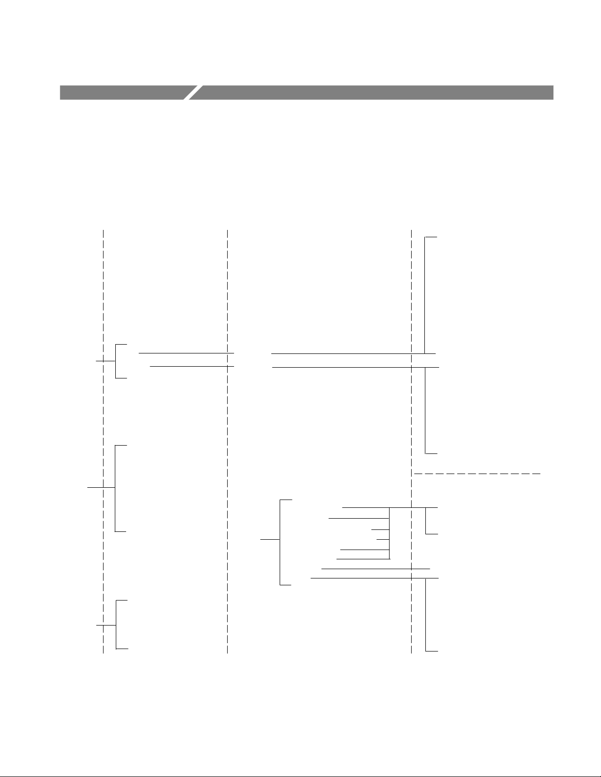
Menu Structure
Figure 13 shows the relationship of the application-specific menus. Available
tests depend on the selected standard and data rate. Refer to Table 9 on page 12
and Table 11 on page 13 for more information.
Main menu Side menus
Standard
Test
Logging
ITU
ANSI
Pulse Amplitude
Peak-Peak
Pulse Imbalance Variation
Pulse Imbalance: Amp Ratio
Pulse Symmetry
Spectral Power
Zero Level
Mask
On/Off
Store Results In:
Clear Log File
Set Drive
Main menu
Data Rate
Data Rate
Setup
Pulse Amplitude
Peak-Peak
Pulse Imbalance Variation
Pulse Imbalance: Amp Ratio
Pulse Symmetry
Spectral Power
Zero Level
Mask
Side menus
E1 2.048 Mb/s Coax Pair
E1 2.048 Mb/s Sym Pair
E2 8.448 Mb/s
E3 34.368 Mb/s
E4 139.26 Mb/s
Old DS1 Rate 1.544 Mb/s
DS1 Rate 1.544 Mb/s
DS2 Rate 6.312 Mb/s
Old DS3 Rate 44.736 Mb/s
DS3 Rate 44.736 Mb/s
STM-1E 155.52 Mb/s
DS1 1.544 Mb/s
DS1A 2.048 Mb/s
DS1C 3.152 Mb/s
DS2 6.312 Mb/s
DS3 44.736 Mb/s
DS4NA 139.26 Mb/s
STS-1 51.840 Mb/s
STS-3 155.52 Mb/s
Side menu items
Input
Num Avg
Input
Input
Num Avg
Mask Symbol
Mask Time Base Adj
Mask Offset Adj
Mask Margin
Figure 13: Application-specific menu structure
TDSCPM1 Communications Pulse Measurements Application User Manual
35
Page 54

Menu Structure
Figure 14 shows the structure of the Control and Utility menus.
Main menu Side menus
Mode: Single/Free Run
Start/Continue
Control
Utility
Pause
Stop
Reset All
On Error
Help
Exit
Save/Recall Setup
Display Options
Side menu items
Stop
Pause
Log and Continue
First Page
Next Page
Previous Page
Last Page
Quit Help
OK
Cancel
Recall Setup
Recall from File:
Save Setup
Save to File:
Done
Dialog Box
Box Style
Color Theme
Done
36
Figure 14: Control and Utility menus structures
TDSCPM1 Communications Pulse Measurements Application User Manual
Page 55

Parameters Reference
This section describes the TDSCPM1 application parameters. You should refer to
the user manual for your oscilloscope for operating details for each front-panel
menu button.
Refer to Appendix B: GPIB Command Syntax for a complete list of the GPIB
command syntax with the arguments, variables and variable values that
correspond to the TDSCPM1 parameters.
Standard Menu
The selections for the Standard menu are as follows:
H
ITU-T G.703
H
ANSI T1.102
Data Rate Menu
For the ITU-T G.703 standard, the data rate selections are as follows:
H
E1 2.048 Mb/s Coax Pair
H
E1 2.048 Mb/s Sym Pair
H
E2 8.448 Mb/s
H
E3 34.368 Mb/s
H
E4 139.26 Mb/s
H
Old DS1 Rate 1.544 Mb/s
H
DS1 Rate 1.544 Mb/s
H
DS2 Rate 6.312 Mb/s
H
Old DS3 Rate 44.736 Mb/s
H
DS3 Rate 44.736 Mb/s
H
STM-1E 155.52 Mb/s
The application takes measurements based on these data rates as they are defined
in the ITU-T Recommendation G.704, General Aspects of Digital Transmission
Systems, ITU-T G.703 document. Table 5 on page 9 lists the location of the data
rate definitions in the standard.
TDSCPM1 Communications Pulse Measurements Application User Manual
37
Page 56

Parameters Reference
For the ANSI T1.102 standard, the data rate selections are as follows:
H
DSI 1.544 Mb/s
H
DSIA 2.048 Mb/s
H
DS1C 3.152 Mb/s
H
DS2 6.312 Mb/s
H
DS3 44.736 Mb/s
H
DS4NA 139.26 Mb/s
H
STS-1 51.840 Mb/s
H
STS-3 155.52 Mb/s
The application takes measurements based on these data rates as they are defined
in the American National Standard for Telecommunications – Digital Hierarchy
– Electrical Interfaces, ANSI T1.102-1993 document. Table 6 on page 9 lists the
location of the data rate definitions in the standard.
Test Menu
For the ITU-T G.703 data rates, the test selections are as follows:
H
Pulse Amplitude (only for AMI signals)
H
Peak-Peak (only for CMI signals)
H
Pulse Imbalance Variation
H
Pulse Imbalance Amp Ratio
H
Pulse Symmetry
H
Zero Level
H
Spectral Power
H
Mask
NOTE. Available tests depend on the selected standard and data rate. Table 9 on
page 12 lists test selections for ITU-T G.703 data rates and Table 11 on page 13
lists test selections for ANSI T1.102
data rates.
38
TDSCPM1 Communications Pulse Measurements Application User Manual
Page 57
Setup Menu
Parameters Reference
For the ANSI T1.102 data rates, the test selections are as follows:
H
Pulse Amplitude
H
Pulse Imbalance Variation
H
Pulse Imbalance Amp Ratio
H
Spectral Power
H
Mask
Table 15 lists the parameters for the Setup menu, the selections available, and the
default settings.
T able 15: Setup menu parameters
Parameter Selections Default setting
Input Ch1, Ch2, Ch3, Ch4 Ch1
Num Avg 2 through 10,000 16
Mask Symbol Binary 0, Binary 1 Binary 0
Mask Time Base Adj Y es, No No
Mask Offset Adj Yes, No No
Mask Margin ##.# -50.0 to 50.0, refer to Table 19 0.0
Mask Time Base Full Mask, Time Details Full Mask
Max Output Mask Yes, No No
Mask Type Pulse, Eye Pulse
For the ITU-T G.703 data rates, the setup parameter selections are as follows:
H
Input
H
Num Avg
H
Mask Symbol
H
Mask Time Base Adj
H
Mask Offset Adj
H
Mask Margin ##.#
TDSCPM1 Communications Pulse Measurements Application User Manual
39
Page 58

Parameters Reference
NOTE. Setup parameters vary by data rate for the Mask test. Table 10 on page 12
lists Mask setup parameters for ITU-T G.703 data rates and Table 12 on page 13
lists Mask setup parameters for ANSI T1.102
data rates.
For the ANSI T1.102 data rates, the setup parameter selections are as follows:
H
Input
H
Num Avg
H
Mask Timebase Adj
H
Mask Offset Adj
H
Mask Margin ##.#
H
Mask Time Base
H
Max. Output Mask
H
Mask Type
Logging Menu
Table 16 lists the parameters for the Logging menu, the selections available, and
the default settings.
T able 16: Logging menu parameters
Parameter Selections Default setting
On/Off On, Off Off
Store Results In: RESULTS.CSV or new file name RESULTS.CSV
Clear Log File None
Select Drive hd0, fd0 hd0
40
TDSCPM1 Communications Pulse Measurements Application User Manual
Page 59

Control Menu
Parameters Reference
Table 17 lists the parameters for the Control menu and the selections available.
T able 17: Control menu parameters
Parameters Selections Default setting
Mode Single, Free Run Single
Start (or Continue) None
Pause None
Stop None
Reset All None
On Error* Stop, Pause, Log and Continue Pause
* When operating in Free Run mode only.
Utility Menus
Table 18 lists each utility menu, the parameters, the selections available and
default settings.
T able 18: Utility menus and parameters
Utility menu Parameters Selections Default setting
Help Refer to Figure 14
on page 36.
Exit Refer to Figure 14
on page 36.
Save/Recall Setup Recall Setup
Recall from File:
Save Setup
Save to File:
Display Options Dialog Box
Box Style
Color Theme
None
None
None
Default, or saved setup files
None
setup1.ini, or new file name
On, Off
Opaque, Transparent
Based on the TDS oscilloscope
color selections
Default
setup1.ini
On
Opaque
TDS Default
TDSCPM1 Communications Pulse Measurements Application User Manual
41
Page 60

Parameters Reference
42
TDSCPM1 Communications Pulse Measurements Application User Manual
Page 61

Appendices
Page 62

Page 63

Appendix A: Measurement Algorithms
The TDSCPM1 application displays a standard pulse-mask pattern behind the
communications signal being acquired. The application also takes measurements
from the communication signal.
Oscilloscope Setup Guidelines
For all measurements, use the following guidelines to set up the oscilloscope:
1. The vertical scale for the communication signal must be set so that the pulse
does not exceed the vertical range of the TDS oscilloscope.
2. The input power level must be less than 250 mW.
Test Methodology
The application performs the measurement according to the following algorithm:
1. Imports the communications signal.
Measurements
Pulse Parameters
Pulse Amplitude
2. Performs the measurement.
3. Uses the results in the Results readout, or saves the results to a data log file.
All communications signal measurements are based on the power level, the
voltage level, or the time locations of edges within each acquisition. Pulse-mask
patterns are defined in the Standard and the Data Rate menus.
The application tests characteristics of communications signals to see if they
meet the value or fall within a range of values expected for certain parameters as
defined in the ITU-T G.703 or ANSI T1.102 standards.
The Pulse Amplitude test measures the amplitude of isolated positive and
negative pulses. This test is performed on standards which uses AMI line coding.
TDSCPM1 Communications Pulse Measurements Application User Manual
43
Page 64

Appendix A: Measurement Algorithms
The application calculates the measurement using the following equation:
Peak-Peak
PA = Avg (PA
Isolated +1
, Abs(PA
Isolated - 1
))
Where: PA is the amplitude of the pulse
Avg is the average of the two input parameters determined by
adding the inputs and dividing it by two
PA
Isolated +1
is the result of the Measure ➞ High measurement
on the oscilloscope of the Isolated +1 signal
PA
Isolated - 1
is the result of the Measure ➞ Low measurement
on the oscilloscope of the Isolated -1 signal
Abs (PA
Isolated - 1
) is the absolute value of its input parameter
The Peak-to-Peak test measures the amplitude of isolated positive and negative
edges. This test is performed on standards which uses CMI line coding.
The application calculates the measurement using the following equation:
PP = Result of the Measure ➞ PK2PK measurement on the oscilloscope
Where: PP is the peak-to-peak amplitude of the pulse
Pulse Imbalance Variation
The Pulse Imbalance Variation measurement is the maximum variation of the
pulse amplitude and pulse widths based on an All 1 signal. The application
assumes that the signal is an All 1s data stream but does not attempt to validate
this.
The application calculates the measurement using the following equations:
PIV(PK2PK Amplitude) = Absolute Average (pkpkPositiveAmplitude, pkpkNegativeAmplitude)
PIV(PK2PK Pulse Width) = Absolute Average (pkpkPositivePW, pkpkNegativePW)
Where: Absolute Average returns the average of its input ignoring the
sign
pkpkPositiveAmplitude is the Peak-to-Peak vertical histogram
variation of the Positive 1 of an AMI 17 consecutive 1s signal
pkpkNegativeAmplitude is the Peak-to-Peak vertical histogram
variation of the Negative 1 of an AMI 17 consecutive 1s signal
pkpkPositivePW is the Peak-to-Peak horizontal histogram
variation of the Positive 1 of an AMI 17 consecutive 1s signal
pkpkNegativePW is the Peak-to-Peak horizontal histogram
variation of the Negative 1 of an AMI 17 consecutive 1s signal
44
TDSCPM1 Communications Pulse Measurements Application User Manual
Page 65

Appendix A: Measurement Algorithms
Pulse Imbalance Amp
Ratio
Pulse Symmetry
The Pulse Imbalance Amp Ratio measurement is the ratio of positive and
negative isolated pulses.
The application calculates the measurement using the following equation:
PulseImbalance Amp ratio = meanPPA/meanNPA
Where: meanPPA is the mean value of the vertical histogram placed on
the positive isolated pulse
meanNPA is the mean value of the vertical histogram placed on
the negative isolated pulse
The Pulse Symmetry measurement is the amplitude and width symmetry of AMI
signals between positive and negative pulses.
The application calculates the measurement using the following equation:
PulseSymmetry(Amp Ratio) = meanPPA/meanNPA
PulseSymmetry(PW Ratio) = meanPositivePW/meanNegativePW
Where: meanPPA is the mean value of the vertical histogram placed on
the positive isolated pulse
Zero Level
meanNPA is the mean value of the vertical histogram placed on
the negative isolated pulse
meanPositivePW is the positive width of Isolated plus 1 signal
meanNegativePW is the negative width of Isolated minus 1
signal
The Zero Level measurement verifies if the maximum and minimum values of a
logical zero (no pulse) signal is within the expected limits for the signal.
The application calculates the measurement using the following equation:
ZeroLevel = Average(ZeroLevelMax, ZeroLevelMin)
Where: ZeroLevelMax is equal to the average of Max1 and Max2
ZerolevelMin is equal to the average of Min1 and Min2
Average is the average of the two input parameters determined
by adding the inputs and dividing it by two
TDSCPM1 Communications Pulse Measurements Application User Manual
45
Page 66

Appendix A: Measurement Algorithms
Max1 is equal to Mean1 + PeakPeak1/2
Min1 is equal to Mean1 - PeakPeak1/2
Max2 is equal to Mean2 + PeakPeak2/2
Min2 is equal to Mean2 -PeakPeak2/2
Mean1 is the mean value of a vertical histogram placed on an
Isolated + 1 pulse
PeakPeak1 is the peak-to-peak value of a vertical histogram
placed on an Isolated + 1 pulse
Mean2 is the mean value of a vertical histogram placed on an
Isolated -1 pulse
PeakPeak2 is the peak-to-peak value of a vertical histogram
placed on an Isolated -1 pulse
Spectral Power
The Spectral Power measurement determines whether a communications signal is
within the spectral power limits set by the ITU-T G.703 or ANSI T1.102
standards. To calculate the spectral power, the application uses the FFT function
of the oscilloscope to convert a time domain signal into a frequency domain
signal.
The application calculates the measurement using the following equation:
N–1
W
+
1
W
N
2
ȍ
k+0
2
X
k
Where: W is the power of the spectrum
W
is the characteristic impedance of the signal being measured,
and not the 50W of the oscilloscope input; the adapter provides
the proper termination and voltage translation so the application
displays the voltage level as if the input of the oscilloscope was
75/100/110/120
W
N is the number of waveform samples
46
TDSCPM1 Communications Pulse Measurements Application User Manual
Page 67

Appendix A: Measurement Algorithms
For the spectral display, the oscilloscope uses the following equation:
Xk
Ǹ
A 2
N
Narrow Band
Where: A is the window adjustment scalar and the
Ǹ
accounts for both
2
the + and - frequencies; A equals 1 for a rectangular window
This means (ignoring A for the moment) that the oscilloscope calculates the
spectral power using the following equation:
N
2–1
W
+
1
W
N
2
ȍ
X
k
2
k+0
The application measures transmitted power in two, 3 kHz " 1 kHz frequency
bands. The center frequencies of the two bands are half the bit rate (fundamental)
and the bit rate (2nd harmonic). The power at the fundamental must fall within a
specified range. The power in the second harmonic must be lower than the
fundamental by a specified amount or more. The measurements are made using
an All 1s signal.
For narrow-band power measurements, you must use a window to correct the
power calculation.
The application uses a Hanning window which results in multiplying the power
by a factor of 2/3rds as shown in the following equation:
M
Wide Band
+
2
3
W
Where: L equals the floor(N((f
The application measures the total power below a designated bandwidth. The
2
ȍ
X
k
W
k+L
center
M equals the floor(N((f
center
bandwidth limit is between 3 to 4 times the bit rate.
For wide band measurements, the range of k should not include DC and the next
bin (such as, start at k=2) and should end at the index that equates to the specified
upper frequency limit.
TDSCPM1 Communications Pulse Measurements Application User Manual
- f
+ f
) B (2 - 1))) B f
width
) B (2 + 1))) B f
width
s
s
47
Page 68

Appendix A: Measurement Algorithms
For wide-band signals (such as other than All 1s), the application uses a
Rectangular window which results in the following equation:
W
+
Mask
The Mask measurement checks the communications signal to see if it conforms
to corresponding mask parameters. This application uses Option 2C on the
oscilloscope to perform this test.
The application offers the following parameters that you can use to customize the
Mask test.
M
1
2
ȍ
X
W
k
k+2
Mask Time Base Adj.
Parameter
Mask Offset Adj.
Parameter
Mask Margin Parameter
Setting this parameter to “Yes” enables the application to find the Mask test
Failure due to marginal time shift. The application performs iterative mask tests
by changing the value of the Time Base Position on the oscilloscope (Measure ➞
Mask menu). The change in the value is based on the standard and data rate
selected.
Setting this parameter to “Yes” enables the standard mask autoset to adjust the
vertical offset so that the waveform can match the mask. The application sets the
Std Mask Offset Adj of the oscilloscope to ON (Measure ➞ Mask menu).
The application uses this parameter to relax or restrict the signal space for a
selected mask. A positive margin causes the signal space to be smaller and makes
the Mask test harder to pass. A negative margin causes the signal space to be
larger and makes the Mask test easier to pass.
Table 19 lists the upper and lower mask margins for each standard and data rate.
T able 19: Mask margin limits
Standard and data rate Upper margin Lower margin
ITU-T G.703
48
E1 Coax 13.6% -32.9%
E1 Sym 14.3% -32.9%
E2 13.6% -32.9%
E3 14.3% -32.9%
E4 (Binary 0) 12.3% -32.9%
TDSCPM1 Communications Pulse Measurements Application User Manual
Page 69

T able 19: Mask margin limits (Cont.)
Standard and data rate Lower marginUpper margin
E4 (Binary 1) 12.3% -32.9%
Old DS1 Rate 6.3% -32.9%
DS1 Rate 6.3% -32.9%
DS2 Rate 5.6% -32.9%
Old DS3 Rate 0% -32.9%
DS3 Rate 5.6% -32.9%
STM-1E (Binary 0) 12.3% -32.9%
STM-1E (Binary 1) 12.3% -32.9%
ANSI T1.102
DS1 6.3% -32.9%
DS1A 6.3% -32.9%
DS1C 8.3% -32.9%
Appendix A: Measurement Algorithms
Mask Symbol Parameter
Mask Timebase Parameter
Max. Output Mask
Parameter
DS2 5.6% -32.9%
DS3 (Time Details) 5.6% -32.9%
DS3 (Full Mask) 5.6% -32.9%
DS4NA 50% -323%
STS-1 (Eye) 38.8% -24.9%
STS-1 (Pulse) 5.6% -32.9%
STS-3 50% -23.4%
STS-3 (Max. Output) 50% -50%
The Mask Symbol parameter is for the ITU-T G.703 E4 and STM-1E data rates
and offers two kinds of masks: Binary 0 or Binary 1.
The Mask Timebase parameter is for the ANSI T1.102 DS3 data rate and offers
two kinds of masks: Full Mask and Time Details.
The Max. Output Mask parameter is for the ANSI T1.102 DS4NA and STS-3
data rates and offers two kinds of masks: Max Output and Standard.
Mask Type Parameter
The Mask Type parameter is for the ANSI T1.102 STS-1 data rate and offers two
kinds of masks: Eye and Pulse.
TDSCPM1 Communications Pulse Measurements Application User Manual
49
Page 70

Appendix A: Measurement Algorithms
50
TDSCPM1 Communications Pulse Measurements Application User Manual
Page 71

Appendix B: GPIB Command Syntax
This appendix describes the GPIB command syntax that you can use in your
GPIB program to do the following tasks:
H
Start the TDSCPM1 application
H
Recognize an active application with GPIB protocol
H
Program and read application setup parameters
H
Sequence measurements
H
Synchronously read measurement results
NOTE. Refer to the GPIB Program Example section for an example of a GPIB
program and for guidelines to use while designing your GPIB program.
To use GPIB commands with your TDS oscilloscope, refer to the programmer
information in the online help of your oscilloscope.
Description. Gives the function of the command, conditions of its use, and its
interactions with other commands.
Syntax. Gives the valid select and query command forms. The required arguments are listed in their proper order.
For example, in the syntax definition
PATH= <Ad><Ars>
the arguments <Ad> and <Ars> are required in the order indicated.
Arguments. The arguments to a command are defined along with their range of
values.
Returns. Defines the data returned in response to a command query.
TDSCPM1 Communications Pulse Measurements Application User Manual
51
Page 72

Appendix B: GPIB Command Syntax
VARIABLE:VALUE TDS COMMAND
Description
VARIABLE:VALUE TDS COMMAND accepts string arguments for a control or
data variable and a value to which to set the argument.
Syntax
VARIABLE:VALUE
VARIABLE:VALUE <variable name>",<variable value>"
the arguments <variable name> and <variable value> are required
in the order indicated.
Arguments and Returns
Table 20 lists the arguments, their function, and the query returns.
T able 20: VARIABLE:VALUE TDS COMMAND arguments and queries
Variable name Variable value Function Query form
application exit Terminates the active applica-
tion
boxBackground {Transparent, Opaque} Sets the message box back-
ground
boxVisibility {On, Off} Sets box visible or invisible Returnsbox visible or invisible
colorTheme {TDS Default, Black, Green, Mild, Purple,
Steel, Tek Blue}
Sets the TDS oscilloscope color
scheme
Returns a string that corresponds to
the name of the active application
Returns the message box background
Returns the TDS oscilloscope color
scheme
logAnnotate* Any string from one to thirty two characters
from A to Z and/or zero to nine
logger {Reset} Clears the current data log file Returns the reset of the data log
loggerDestination Any string from one to eight characters
from A to Z and/or zero to nine
logDrive {fd0, hd0} Sets the state of the data log Returns the state of the data log
loggerState {On, Off} Sets the drive used for logging Returns the drive used for logging
recallName Any string that uses one to eight charac-
ters from A to Z and/or zero to nine
saveName Any string from one to eight characters
from A to Z and/or zero to nine
setup {Default, Recall, Save} Sets the setup file name Returns the setup file name
sequencerMode {Free Run, Single} Sets the sequencer mode Returns the sequencer mode
sequencerState {Ready, Paused, Sequencing} Sets the state of the sequencer Returns the state of the sequencer
standard {ANSI, ITU–T} Sets the communications
52
TDSCPM1 Communications Pulse Measurements Application User Manual
Provides custom annotation to
the data log file
Sets the data log file name Returns the data log file name
Sets the recalled setup file
name
Sets setup file name Returns the setup file name
standard
None
Returns the saved setup file name
Returns the communications
standard
Page 73

T able 20: VARIABLE:VALUE TDS COMMAND arguments and queries (Cont.)
Variable name Query formFunctionVariable value
dataRate {E1 Coax, E1 Sym, E2, E3, E4, Old DS1
Rate, DS1 Rate, DS2 Rate, Old DS3
Rate, DS3 Rate, STM-1E, DS1, DS1A,
DS1C, DS2, DS3, DS4NA, STS-1, STS-3}
Sets the transmission rate of
the data communications signal
Appendix B: GPIB Command Syntax
Returns the transmission rate of the
data communications signal
source {Ch1, Ch2, Ch3, Ch4} Sets the channel from which
input will be received
test {PA, PP, PIV, PIA, PS, ZL, SP, MASK} Sets the name of the current
test
numAvg {2 to 10000} Sets the averaging window size
of the acquisition
maskInfo {Binary 0, Binary 1, Eye, Pulse, Full Mask,
Time Details, Yes, No}
maskTimeBaseAdj
maskOffsetAdj {Yes, No} Sets the mask offset adjustment
maskMargin {–50.0 to +50.0}† Sets the margin value of a
* Custom annotation in the data log file is only available through GPIB execution of the application.
† Refer to Table 19 for mask margin values by data rate.
{Y es, No} Sets the timebase adjustment
Sets additional information for
the mask
of the pulse-mask pattern
of the pulse-mask pattern
pulse-mask pattern
Returns the channel from which
input will be received
Gets the name of the current test
Returns the averaging window size
of the acquisition
Gets additional information for the
mask
Returns the timebase adjustment of
the pulse-mask pattern
Returns the mask offset adjustment
of the pulse-mask pattern
Returns the margin value of a
pulse-mask pattern
Table 21 lists the measurement results queries.
T able 21: Measurement results queries
Variable name Function
error Returns the error dialog box, if one exists, associated with the last
measurement
resultV alue Returns the result of the last test in the Name, V alue, Remarks format
TDSCPM1 Communications Pulse Measurements Application User Manual
53
Page 74

Appendix B: GPIB Command Syntax
54
TDSCPM1 Communications Pulse Measurements Application User Manual
Page 75

Index
Page 76

Page 77

Index
Symbols
.CSV file
copying, 27
custom annotation with GPIB command, 16
definition, 26
example, 17
format, 15
importing, 16
path on the oscilloscope, 27
saving, 15
viewing on a personal computer, 28
A
accessories, 2
ANSI T1.102 data rates
setup parameters, 13
test selections, 13
application
basic functions with an oscilloscope, 6
description, 1
exiting, 19
GPIB program example, 30
installing, 3
menu structure, 5, 35
returning, 7
setting up
communications standard, 8
data rates, 8
parameters, 11
to save results to a data log file, 15
to take measurments, 10
starting, 22
test algorithms, 43
tutorial, 21
updates, 2
viewing the results, 16
Control menu, 14
parameters, 41
conventions, viii
D
data log file
custom annotation with GPIB command, 16
example, 17
format, 15
importing, 16
saving, 15
saving the results tutorial lesson, 25
Data Rate menu, 8
parameters, 37
data rates
selections
ANSI T1.102, 9
ITU-T G.703, 9
valid Mask setup parameters
ANSI T1.102, 13
ITU-T G.703, 12
valid test selections
ANSI T1.102, 13
ITU-T G.703, 12
Default Setup, 19
dialog box, turning off, 17
dialog boxes, changing the appearance, 7
disk
full message, 15
not present message, 15
display , viewing obscured parts, 17
Display Options menu, 7
Done, 6
E
exiting the application, 19
C
Cancel, 6
changing settings during a measurement, 15
CLEAR MENU button, 17
command syntax, GBIP protocol, 51
common menu items, 6
configuring the display, 7
connecting to a system under test, 4
F
Free Run acquisition mode, 14
G
GPIB protocol
command syntax, 51
TDSCPM1 Communications Pulse Measurements Application User Manual
55
Page 78

Index
custom annotation for the data log file, 16
guidelines, 29
oscilloscope operation, vii
program example, 30
H
Help, online, 6
I
installation
application, 3
downloading updates, 2
ITU-T G.703 data rates
setup parameters, 11
test selections, 11
L
leaving the application, 19
lessons. See tutorial lessons
log file, example, 17
Logging menu, 15
parameters, 40
test selections, 10
turning off display, 17
tutorial lessons, 21
menu structure
description, 5
detailed illustration, 35
menus
Control, 14
Data Rate, 8
Display Options, 7
Setup, 11
Standard, 8
T est, 10
O
Okay , 6
On Error, 14
online help, 6
oscilloscope
basic functions with the application, 6
compatibility, 1
setup guidelines, 43
P
M
main menus, 5
Mask T ype parameter, application equation, 49
Mask Margin parameter, application equation, 48
Mask Offset Adj. parameter, application equation, 48
Mask setup parameters
ANSI T1.102 data rates, 13
descriptions, 11
ITU-T G.703 data rates, 12
Mask Symbol parameter, application equation, 49
Mask test, application equation, 48
Mask Time Base Adj. parameter , application
equation, 48
Mask Timebase parameter, application equation, 49
Max. Output Mask parameter, application equation, 49
measurements
application test method, 43
example of viewing the results, 16
GPIB program example, 30
oscilloscope changes, 15
setting up, 8
setup parameter selections, 11
taking, 14
test algorithms, 43
parameters, reference, 37
Peak-Peak test, application equation, 44
product
compatibility, 1
description, 1
requirements and restrictions, 2
updates, 2
Pulse Amplitude test, application equation, 43
Pulse Imbalance Amp Ratio test, application
equation, 45
Pulse Imbalance Variation test, application equation, 44
Pulse Symmetry test, application equation, 45
Q
quitting the application, 19
R
Recall from File:, 19
Recall Setup, 19
recalling a setup, 19
requirements and restrictions, 2
Reset All, 14
56
TDSCPM1 Communications Pulse Measurements Application User Manual
Page 79

Index
Results readout
turning off, 17
viewing obscured parts, 17
S
Save Setup, 18
Save to File:, 18
Save/Recall Setup menu, 18
setup
default, 19
recalling, 19
saving, 18
Setup menu, 11
parameters, 39
setup parameters, descriptions, 11
side menus, 5
Single acquisition mode, 14
Spectral Power test
application equation, 46
narrow-band equation, 47
wide-band equation, 47
Standard menu, 8
parameters, 37
starting, application, 22
system under test, 4
test selections
ANSI T1.102 data rates, 13
descriptions, 10
ITU-T G.703 data rates, 12
tutorial lessons, 21
Results readout, 25
returning to the application, 28
saving the results to a data log file, 25
setting up the oscilloscope, 21
starting the application, 22
stopping the application, 28
taking a measurement, 23
U
Utility menus
descriptions, 6
parameters, 41
V
VARIABLE:VALUE TDS COMMAND, 52
viewing, obscured parts of the display, 17
W
T
terms, viii
T est menu, 10
parameters, 38
waveforms, display color, 7
web site, 2
Z
Zero Level test, application equation, 45
TDSCPM1 Communications Pulse Measurements Application User Manual
57
Page 80

Index
58
TDSCPM1 Communications Pulse Measurements Application User Manual
Page 81

Page 82

 Loading...