

Page 1

Service Manual
CSA8000
Communications Signal Analyzer
TDS8000
Digital Sampling Oscilloscope
071-0438-01
Warning
The servicing instructions are for use by qualified
personnel only. To avoid personal injury, do not
perform any servicing unless you are qualified to
do so. Refer to all safety summaries prior to
performing service.
www.tektronix.com
Page 2

Copyright © T ektronix, Inc. All rights reserved.
T ektronix products are covered by U.S. and foreign patents, issued and pending. Information in this publication supercedes
that in all previously published material. Specifications and price change privileges reserved.
T ektronix, Inc., P.O. Box 500, Beaverton, OR 97077
TEKTRONIX and TEK are registered trademarks of T ektronix, Inc.
Page 3

WARRANTY
T ektronix warrants that the products that it manufactures and sells will be free from defects in materials and workmanship
for a period of one (1) year from the date of shipment. If this product proves defective during its warranty period,
T ektronix, at its option, will either repair the defective product without charge for parts and labor, or provide a replacement
in exchange for the defective product.
This warranty applies only to products returned to the designated T ektronix depot or the Tektronix authorized
representative from which the product was originally purchased. For products returned to other locations, Customer will be
assessed an applicable service charge. The preceding limitation shall not apply within the European Economic Area, where
products may be returned for warranty service to the nearest designated service depot regardless of the place of purchase.
In order to obtain service under this warranty, Customer must provide the applicable office of Tektronix or its authorized
representative with notice of the defect before the expiration of the warranty period and make suitable arrangements for the
performance of service. Customer shall be responsible for packaging and shipping the defective product to the service
center designated by T ektronix or its representative, with shipping charges prepaid. Tektronix or its representative shall pay
for the return of the product to Customer. Customer shall be responsible for paying any associated taxes or duties.
This warranty shall not apply to any defect, failure or damage caused by improper use or improper or inadequate
maintenance and care. T ektronix shall not be obligated to furnish service under this warranty:
a) to repair damage resulting from attempts by personnel other than T ektronix representatives to install, repair or service
the product;
b) to repair damage resulting from improper use or connection to incompatible equipment;
c) to repair any damage or malfunction caused by the use of non-T ektronix supplies or consumables;
d) to repair a product that has been modified or integrated with other products when the effect of such modification or
integration increases the time or difficulty of servicing the product; or
e) to repair damage or malfunction resulting from failure to perform user maintenance and cleaning at the frequency and
as prescribed in the user manual (if applicable).
THE ABOVE WARRANTIES ARE GIVEN BY TEKTRONIX WITH RESPECT TO THIS PRODUCT IN LIEU OF ANY OTHER
WARRANTIES, EXPRESS OR IMPLIED. TEKTRONIX AND ITS VENDORS DISCLAIM ANY IMPLIED WARRANTIES OF
MERCHANTABILITY OR FITNESS FOR A PARTICULAR PURPOSE. TEKTRONIX’ RESPONSIBILITY TO REPAIR OR
REPLACE DEFECTIVE PRODUCTS IS THE SOLE AND EXCLUSIVE REMEDY PROVIDED TO THE CUSTOMER FOR
BREACH OF THIS WARRANTY. TEKTRONIX AND ITS VENDORS WILL NOT BE LIABLE FOR ANY INDIRECT,
SPECIAL, INCIDENTAL, OR CONSEQUENTIAL DAMAGES IRRESPECTIVE OF WHETHER TEKTRONIX OR THE
VENDOR HAS ADVANCE NOTICE OF THE POSSIBILITY OF SUCH DAMAGES.
Page 4

Page 5

Table of Contents
Specifications
Operating Information
General Safety Summary xi. . . . . . . . . . . . . . . . . . . . . . . . . . . . . . . . . . . .
Service Safety Summary xiii. . . . . . . . . . . . . . . . . . . . . . . . . . . . . . . . . . . . .
Manual Structure xv. . . . . . . . . . . . . . . . . . . . . . . . . . . . . . . . . . . . . . . . . . . . . . . . .
Manual Conventions xv. . . . . . . . . . . . . . . . . . . . . . . . . . . . . . . . . . . . . . . . . . . . . .
Related Documentation xvi. . . . . . . . . . . . . . . . . . . . . . . . . . . . . . . . . . . . . . . . . . . .
Contacting T ektronix xvii. . . . . . . . . . . . . . . . . . . . . . . . . . . . . . . . . . . . . . . . . . . . . .
System Specifications 1–1. . . . . . . . . . . . . . . . . . . . . . . . . . . . . . . . . . . . . . .
Certifications 1–9. . . . . . . . . . . . . . . . . . . . . . . . . . . . . . . . . . . . . . . . . . . . . . . . . . . .
80E00 Electrical Sampling Modules 1–11. . . . . . . . . . . . . . . . . . . . . . . . . . .
80C00 Optical Modules 1–17. . . . . . . . . . . . . . . . . . . . . . . . . . . . . . . . . . . . . .
80A01 Trigger Prescale Preamplifier Module 1–37. . . . . . . . . . . . . . . . . . .
Installation
Check the Environmental Requirements 2–1. . . . . . . . . . . . . . . . . . . . . . . . . . . . . . .
Install the Sampling Modules 2–2. . . . . . . . . . . . . . . . . . . . . . . . . . . . . . . . . . . . . . . .
Connect the Peripherals 2–4. . . . . . . . . . . . . . . . . . . . . . . . . . . . . . . . . . . . . . . . . . . .
Power On the Instrument 2–5. . . . . . . . . . . . . . . . . . . . . . . . . . . . . . . . . . . . . . . . . . .
Powering Off the Instrument 2–7. . . . . . . . . . . . . . . . . . . . . . . . . . . . . . . . . . . . . . . .
Software Installation 2–7. . . . . . . . . . . . . . . . . . . . . . . . . . . . . . . . . . . . . . . . . . . . . .
Description 2–7. . . . . . . . . . . . . . . . . . . . . . . . . . . . . . . . . . . . . . . . . . . . . . . . . .
Software Release Notes 2–8. . . . . . . . . . . . . . . . . . . . . . . . . . . . . . . . . . . . . . . .
Operating System Reinstallation 2–8. . . . . . . . . . . . . . . . . . . . . . . . . . . . . . . . . .
Windows 98 Reinstall Only. 2–8. . . . . . . . . . . . . . . . . . . . . . . . . . . . . . . . . . . . .
System Diagnostics 2–9. . . . . . . . . . . . . . . . . . . . . . . . . . . . . . . . . . . . . . . . . . . .
Operating Instructions 2–11. . . . . . . . . . . . . . . . . . . . . . . . . . . . . . . . . . . . . .
Documentation Map 2–12. . . . . . . . . . . . . . . . . . . . . . . . . . . . . . . . . . . . . . . . . . . . . . .
User Interface Map – Complete Control and Display 2–13. . . . . . . . . . . . . . . . . . . . .
Front Panel Map – Quick Access to Most Often Used Features 2–14. . . . . . . . . . . . .
Display Map – Single Graticule View 2–15. . . . . . . . . . . . . . . . . . . . . . . . . . . . . . . . .
Front Panel I/O Map 2–15. . . . . . . . . . . . . . . . . . . . . . . . . . . . . . . . . . . . . . . . . . . . . . .
Rear Panel I/O Map 2–16. . . . . . . . . . . . . . . . . . . . . . . . . . . . . . . . . . . . . . . . . . . . . . .
How to Use Online Help 2–17. . . . . . . . . . . . . . . . . . . . . . . . . . . . . . . . . . . . . . . . . . .
80E00 Electrical Sampling Module Operation 2–23. . . . . . . . . . . . . . . . . . . . . . . . . .
Signal Connector 2–23. . . . . . . . . . . . . . . . . . . . . . . . . . . . . . . . . . . . . . . . . . . . . .
Channel Selection 2–24. . . . . . . . . . . . . . . . . . . . . . . . . . . . . . . . . . . . . . . . . . . . .
TEKPROBE Connector 2–24. . . . . . . . . . . . . . . . . . . . . . . . . . . . . . . . . . . . . . . .
TDR On Indicator 2–24. . . . . . . . . . . . . . . . . . . . . . . . . . . . . . . . . . . . . . . . . . . . .
CSA8000 & TDS8000 Instruments and Sampling Modules
i
Page 6

Table of Contents
80C00 Optical Sampling Module Operation 2–25. . . . . . . . . . . . . . . . . . . . . . . . . . . .
Attenuating Optical Signals 2–25. . . . . . . . . . . . . . . . . . . . . . . . . . . . . . . . . . . . .
Channel Selection 2–26. . . . . . . . . . . . . . . . . . . . . . . . . . . . . . . . . . . . . . . . . . . . .
Optical Input Connector 2–26. . . . . . . . . . . . . . . . . . . . . . . . . . . . . . . . . . . . . . . .
Clock Recovery Outputs 2–26. . . . . . . . . . . . . . . . . . . . . . . . . . . . . . . . . . . . . . . .
Hold-Down Screws 2–27. . . . . . . . . . . . . . . . . . . . . . . . . . . . . . . . . . . . . . . . . . . .
80A01 Trigger Prescale Preamplifier Module Operation 2–27. . . . . . . . . . . . . . . . . .
Signal Connector 2–28. . . . . . . . . . . . . . . . . . . . . . . . . . . . . . . . . . . . . . . . . . . . . .
Theory of Operation
Logic Conventions 3–1. . . . . . . . . . . . . . . . . . . . . . . . . . . . . . . . . . . . . . . . . . . . . . . .
Mainframe Overview 3–1. . . . . . . . . . . . . . . . . . . . . . . . . . . . . . . . . . . . . . . . . . . . . .
Performance V erification Procedures
Brief Procedures 4–3. . . . . . . . . . . . . . . . . . . . . . . . . . . . . . . . . . . . . . . . . . .
Perform the Diagnostics 4–3. . . . . . . . . . . . . . . . . . . . . . . . . . . . . . . . . . . . . . . . . . .
Perform the Compensation 4–5. . . . . . . . . . . . . . . . . . . . . . . . . . . . . . . . . . . . . . . . . .
Perform the Functional T ests 4–7. . . . . . . . . . . . . . . . . . . . . . . . . . . . . . . . . . . . . . . .
Perform the Hardware and Operating System T ests 4–15. . . . . . . . . . . . . . . . . . . . . .
Performance Tests 4–19. . . . . . . . . . . . . . . . . . . . . . . . . . . . . . . . . . . . . . . . . .
Prerequisites 4–19. . . . . . . . . . . . . . . . . . . . . . . . . . . . . . . . . . . . . . . . . . . . . . . . . . . . .
Equipment Required 4–19. . . . . . . . . . . . . . . . . . . . . . . . . . . . . . . . . . . . . . . . . . . . . . .
CSA8000/TDS8000 T est Records 4–23. . . . . . . . . . . . . . . . . . . . . . . . . . . . . . . . . . . .
CSA8000/TDS8000 Main-Instrument T est Record 4–24. . . . . . . . . . . . . . . . . . . . . . .
80E00 Electrical Modules T est Record 4–25. . . . . . . . . . . . . . . . . . . . . . . . . . . . . . . .
80C00 Optical Modules T est Record 4–28. . . . . . . . . . . . . . . . . . . . . . . . . . . . . . . . . .
Main Instrument 4–33. . . . . . . . . . . . . . . . . . . . . . . . . . . . . . . . . . . . . . . . . . . . . . . . . .
Prerequisites 4–33. . . . . . . . . . . . . . . . . . . . . . . . . . . . . . . . . . . . . . . . . . . . . . . . . . . . .
Time interval accuracy, short-term optimized and locked-to-internal
10-MHz reference modes 4–34. . . . . . . . . . . . . . . . . . . . . . . . . . . . . . . . . . . . . . .
External direct trigger level accuracy 4–37. . . . . . . . . . . . . . . . . . . . . . . . . . . . . . . . .
External direct trigger sensitivity 4–40. . . . . . . . . . . . . . . . . . . . . . . . . . . . . . . . . . . . .
External direct trigger delay jitter, short term optimized and locked to internal 10 MHz
reference modes 4–43. . . . . . . . . . . . . . . . . . . . . . . . . . . . . . . . . . . . . . . . . . . . . .
External prescaled trigger delay jitter, short term optimized mode and locked to internal
10 MHz reference mode 4–47. . . . . . . . . . . . . . . . . . . . . . . . . . . . . . . . . . . . . . . .
External prescaled trigger sensitivity 4–50. . . . . . . . . . . . . . . . . . . . . . . . . . . . . . . . . .
Electrical Sampling Modules 4–53. . . . . . . . . . . . . . . . . . . . . . . . . . . . . . . . .
Prerequisites 4–53. . . . . . . . . . . . . . . . . . . . . . . . . . . . . . . . . . . . . . . . . . . . . . . . . . . . .
Input impedance 4–53. . . . . . . . . . . . . . . . . . . . . . . . . . . . . . . . . . . . . . . . . . . . . . . . . .
DC voltage measurement accuracy 4–56. . . . . . . . . . . . . . . . . . . . . . . . . . . . . . . . . . .
Random noise, displayed 4–62. . . . . . . . . . . . . . . . . . . . . . . . . . . . . . . . . . . . . . . . . . .
Rise time (80E02, 80E03, & 80E04) 4–64. . . . . . . . . . . . . . . . . . . . . . . . . . . . . . . . . .
Analog bandwidth (80E01) 4–67. . . . . . . . . . . . . . . . . . . . . . . . . . . . . . . . . . . . . . . . .
TDR system reflected rise time (80E04) 4–75. . . . . . . . . . . . . . . . . . . . . . . . . . . . . . .
TDR system step response aberrations (80E04) 4–78. . . . . . . . . . . . . . . . . . . . . . . . .
Optical Sampling Modules 4–83. . . . . . . . . . . . . . . . . . . . . . . . . . . . . . . . . . .
Dark Level & Vertical Equivalent Optical Noise 4–83. . . . . . . . . . . . . . . . . . . . . . . . .
Minimum Optical Bandwidth & Reference Receiver Frequency Response 4–88. . . .
Integrated Rise Time 80C06 4–99. . . . . . . . . . . . . . . . . . . . . . . . . . . . . . . . . . . . . . . .
ii
CSA8000 & TDS8000 Instruments and Sampling Modules
Page 7

Adjustment Procedures
Maintenance
Table of Contents
Clock Recovery Optical Sensitivity Range and Recovered Clock Timing Jitter 4–103.
80A01 Trigger Prescale Limiting Preamplifier Module 4–111. . . . . . . . . . .
Prerequisites 4–111. . . . . . . . . . . . . . . . . . . . . . . . . . . . . . . . . . . . . . . . . . . . . . . . . . . . .
System Trigger Sensitivity 4–111. . . . . . . . . . . . . . . . . . . . . . . . . . . . . . . . . . . . . . . . . .
Adjustment Interval 5–1. . . . . . . . . . . . . . . . . . . . . . . . . . . . . . . . . . . . . . . . . . . . . . .
Adjustment Environment 5–1. . . . . . . . . . . . . . . . . . . . . . . . . . . . . . . . . . . . . . . . . . .
Adjustment After Repair 5–1. . . . . . . . . . . . . . . . . . . . . . . . . . . . . . . . . . . . . . . . . . .
Required Equipment 5–2. . . . . . . . . . . . . . . . . . . . . . . . . . . . . . . . . . . . . . . . . . . . . . .
Instrumentation Setup 5–2. . . . . . . . . . . . . . . . . . . . . . . . . . . . . . . . . . . . . . . . . . . . .
Main Instrument Adjustments 5–3. . . . . . . . . . . . . . . . . . . . . . . . . . . . . . . . . . . . . . .
DC Calibrator Adjust 5–3. . . . . . . . . . . . . . . . . . . . . . . . . . . . . . . . . . . . . . . . . .
DC Calibrator Adjust Verification 5–4. . . . . . . . . . . . . . . . . . . . . . . . . . . . . . . .
Internal 10 MHz Adjust 5–5. . . . . . . . . . . . . . . . . . . . . . . . . . . . . . . . . . . . . . . .
Preventing ESD 6–1. . . . . . . . . . . . . . . . . . . . . . . . . . . . . . . . . . . . . . . . . . . . . . . . . .
Inspection and Cleaning 6–2. . . . . . . . . . . . . . . . . . . . . . . . . . . . . . . . . . . . . . . . . . . .
Interior Cleaning 6–2. . . . . . . . . . . . . . . . . . . . . . . . . . . . . . . . . . . . . . . . . . . . . .
Exterior Cleaning 6–2. . . . . . . . . . . . . . . . . . . . . . . . . . . . . . . . . . . . . . . . . . . . .
Removal and Installation Procedures 6–7. . . . . . . . . . . . . . . . . . . . . . . . . .
Preparation 6–7. . . . . . . . . . . . . . . . . . . . . . . . . . . . . . . . . . . . . . . . . . . . . . . . . . . . . .
Procedures for External Modules 6–9. . . . . . . . . . . . . . . . . . . . . . . . . . . . . . . . . . . . .
Procedures for Modules 6–21. . . . . . . . . . . . . . . . . . . . . . . . . . . . . . . . . . . . . . . . . . . .
Exchanging electrical sampling module 6–62. . . . . . . . . . . . . . . . . . . . . . . . . . . . . . .
Troubleshooting 6–67. . . . . . . . . . . . . . . . . . . . . . . . . . . . . . . . . . . . . . . . . . . .
Service Level 6–67. . . . . . . . . . . . . . . . . . . . . . . . . . . . . . . . . . . . . . . . . . . . . . . . . . . .
Check for Common Problems 6–67. . . . . . . . . . . . . . . . . . . . . . . . . . . . . . . . . . . . . . .
Equipment Required 6–70. . . . . . . . . . . . . . . . . . . . . . . . . . . . . . . . . . . . . . . . . . . . . . .
Isolating Failures between the 80E0X/80C0X Modules or the Mainframe 6–70. . . . .
Checking the Power Supply Voltages 6–72. . . . . . . . . . . . . . . . . . . . . . . . . . . . . . . . .
PPC and NLX PC Diagnostics 6–74. . . . . . . . . . . . . . . . . . . . . . . . . . . . . . . . . . . . . . .
Firmware Updates 6–75. . . . . . . . . . . . . . . . . . . . . . . . . . . . . . . . . . . . . . . . . . . . . . . .
After Repair 6–76. . . . . . . . . . . . . . . . . . . . . . . . . . . . . . . . . . . . . . . . . . . . . . . . . . . . .
BIOS Error Messages 6–77. . . . . . . . . . . . . . . . . . . . . . . . . . . . . . . . . . . . . . . . . . . . . .
BIOS Beep Codes 6–78. . . . . . . . . . . . . . . . . . . . . . . . . . . . . . . . . . . . . . . . . . . . . . . .
Installing the Instrument Model and Serial Number 6–79. . . . . . . . . . . . . . . . . . . . . .
Update/Restore the NLX Board CMOS 6–80. . . . . . . . . . . . . . . . . . . . . . . . . . . . . . . .
Repackaging Instructions 6–81. . . . . . . . . . . . . . . . . . . . . . . . . . . . . . . . . . . .
Packaging 6–81. . . . . . . . . . . . . . . . . . . . . . . . . . . . . . . . . . . . . . . . . . . . . . . . . . . . . . .
Shipping to the Service Center 6–81. . . . . . . . . . . . . . . . . . . . . . . . . . . . . . . . . . . . . . .
CSA8000 & TDS8000 Instruments and Sampling Modules
iii
Page 8

Table of Contents
Options and Accessories
Standard Accessories 7–2. . . . . . . . . . . . . . . . . . . . . . . . . . . . . . . . . . . . . . . . . . . . . .
Optional Accessories 7–3. . . . . . . . . . . . . . . . . . . . . . . . . . . . . . . . . . . . . . . . . . . . . .
Options 7–4. . . . . . . . . . . . . . . . . . . . . . . . . . . . . . . . . . . . . . . . . . . . . . . . . . . . . . . . .
Electrical Parts List
Diagrams
Symbols 9–16. . . . . . . . . . . . . . . . . . . . . . . . . . . . . . . . . . . . . . . . . . . . . . . . . . . . . . . .
Mechanical Parts List
Parts Ordering Information 10–1. . . . . . . . . . . . . . . . . . . . . . . . . . . . . . . . . . . . . . . . .
Using the Replaceable Parts List 10–2. . . . . . . . . . . . . . . . . . . . . . . . . . . . . . . . . . . . .
iv
CSA8000 & TDS8000 Instruments and Sampling Modules
Page 9

List of Figures
Table of Contents
Figure 2–1: Compartments for sampling modules 2–3. . . . . . . . . . . . . . . .
Figure 2–2: Maximum inputs in three configurations 2–3. . . . . . . . . . . . .
Figure 2–3: Locations of peripheral connectors on rear panel 2–5. . . . . .
Figure 2–4: Line fuse and power cord connector locations,
rear panel 2–6. . . . . . . . . . . . . . . . . . . . . . . . . . . . . . . . . . . . . . . . . . . . . .
Figure 2–5: On/Standby switch location 2–7. . . . . . . . . . . . . . . . . . . . . . . .
Figure 2–6: Sampling module, 80E04 shown 2–23. . . . . . . . . . . . . . . . . . . .
Figure 2–7: Sampling module, 80C01-CR shown 2–26. . . . . . . . . . . . . . . . .
Figure 2–8: 80A01 module front panel 2–27. . . . . . . . . . . . . . . . . . . . . . . . .
Figure 4–1: Compensation dialog box 4–5. . . . . . . . . . . . . . . . . . . . . . . . . .
Figure 4–2: Hookup for electrical functional tests 4–8. . . . . . . . . . . . . . . .
Figure 4–3: Channel button location 4–8. . . . . . . . . . . . . . . . . . . . . . . . . . .
Figure 4–4: Channel button location 4–10. . . . . . . . . . . . . . . . . . . . . . . . . . .
Figure 4–5: Optical channel verification 4–11. . . . . . . . . . . . . . . . . . . . . . . .
Figure 4–6: Hookup for the time base tests 4–12. . . . . . . . . . . . . . . . . . . . .
Figure 4–7: Channel button location 4–13. . . . . . . . . . . . . . . . . . . . . . . . . . .
Figure 4–8: Main time base verification 4–14. . . . . . . . . . . . . . . . . . . . . . . .
Figure 4–9: Mag time base verification 4–15. . . . . . . . . . . . . . . . . . . . . . . . .
Figure 4–10: Time interval accuracy test hookup 4–34. . . . . . . . . . . . . . . .
Figure 4–11: External direct trigger test hookup 4–37. . . . . . . . . . . . . . . . .
Figure 4–12: External direct trigger sensitivity test hookup 4–40. . . . . . . .
Figure 4–13: External direct trigger jitter test hookup 4–43. . . . . . . . . . . .
Figure 4–14: External prescaled test hookup 4–47. . . . . . . . . . . . . . . . . . . .
Figure 4–15: External prescaled trigger sensitivity test hookup 4–50. . . . .
Figure 4–16: Input impedance test hookup 4–54. . . . . . . . . . . . . . . . . . . . .
Figure 4–17: Vertical DC accuracy test hookup 4–57. . . . . . . . . . . . . . . . . .
Figure 4–18: Rise Time hookup 4–64. . . . . . . . . . . . . . . . . . . . . . . . . . . . . . .
Figure 4–19: Power-reference hookup 4–67. . . . . . . . . . . . . . . . . . . . . . . . . .
Figure 4–20: Adapter characterization hookup 4–69. . . . . . . . . . . . . . . . . .
Figure 4–21: Measure reference signals 4–70. . . . . . . . . . . . . . . . . . . . . . . .
Figure 4–22: 80E01 reference signals hookup 4–72. . . . . . . . . . . . . . . . . . .
Figure 4–23: TDR reflected rise time hookup 4–75. . . . . . . . . . . . . . . . . . .
Figure 4–24: TDR system step response aberrations hookup 4–78. . . . . . .
Figure 4–25: Dark Level and Vertical Equivalent Optical
Noise test hookup 4–83. . . . . . . . . . . . . . . . . . . . . . . . . . . . . . . . . . . . . . .
CSA8000 & TDS8000 Instruments and Sampling Modules
v
Page 10

Table of Contents
Figure 4–26: Minimum optical bandwidth and reference
receiver frequency response hookup 4–90. . . . . . . . . . . . . . . . . . . . . . . .
Figure 4–27: Proper positioning of the impulse for optimum
curve download 4–94. . . . . . . . . . . . . . . . . . . . . . . . . . . . . . . . . . . . . . . .
Figure 4–28: Minimum optical bandwidth and reference
receiver frequency response hookup 4–100. . . . . . . . . . . . . . . . . . . . . . . .
Figure 4–29: 80C01 and 80C03 clock recovery optical sensitivity
range and recovered clock timing jitter hookup 4–104. . . . . . . . . . . . . .
Figure 4–30: Example of the display when the clock signal from the
80C0X-CR Optical Sampling Module is not synchronous with the data
rate input from the pulse pattern generator. Note the unstable (“washed
out”) clock signal. Compare this with Figure 4–31, in which the clock
signal is synchronized. 4–108. . . . . . . . . . . . . . . . . . . . . . . . . . . . . . . . . . .
Figure 4–31: Example of the display when the clock signal from the
80C0X-CR Optical Sampling Module is synchronous with the data rate
input from the pulse pattern generator. Note the stable clock signal
waveform. Compare this with Figure 4–30, in which the clock signal is
not synchronized. 4–109. . . . . . . . . . . . . . . . . . . . . . . . . . . . . . . . . . . . . . .
Figure 4–32: Example of the display zoomed in to 10 mV/div and 10 ps/div
at the crossing point (50%) on the recovered clock signal (C3). 4–110.
Figure 4–33: 80A00 test hookup 4–112. . . . . . . . . . . . . . . . . . . . . . . . . . . . . . .
Figure 5–1: Adjustment setup using the DMM 5–3. . . . . . . . . . . . . . . . . .
Figure 5–2: Adjustment setup using the signal generator 5–5. . . . . . . . . .
Figure 6–1: Knob removal 6–9. . . . . . . . . . . . . . . . . . . . . . . . . . . . . . . . . . .
Figure 6–2: Trim removal 6–11. . . . . . . . . . . . . . . . . . . . . . . . . . . . . . . . . . . .
Figure 6–3: Bottom cover removal 6–12. . . . . . . . . . . . . . . . . . . . . . . . . . . .
Figure 6–4: Cover removal 6–14. . . . . . . . . . . . . . . . . . . . . . . . . . . . . . . . . . .
Figure 6–5: Cover removal 6–15. . . . . . . . . . . . . . . . . . . . . . . . . . . . . . . . . . .
Figure 6–6: Line fuses and line cord removal 6–17. . . . . . . . . . . . . . . . . . . .
Figure 6–7: External modules 6–18. . . . . . . . . . . . . . . . . . . . . . . . . . . . . . . .
Figure 6–8: Internal modules 6–19. . . . . . . . . . . . . . . . . . . . . . . . . . . . . . . . .
Figure 6–9: Acquisition modules 6–20. . . . . . . . . . . . . . . . . . . . . . . . . . . . . .
Figure 6–10: Front panel assembly removal 6–23. . . . . . . . . . . . . . . . . . . . .
Figure 6–11: J1 flex cable connector removal 6–24. . . . . . . . . . . . . . . . . . . .
Figure 6–12: Front panel board & keyboard removal 6–25. . . . . . . . . . . . .
Figure 6–13: Display removal 6–27. . . . . . . . . . . . . . . . . . . . . . . . . . . . . . . . .
Figure 6–14: Touch panel & LCD assembly removal 6–28. . . . . . . . . . . . .
Figure 6–15: Display adaptor board removal 6–29. . . . . . . . . . . . . . . . . . . .
Figure 6–16: Standby/On switch flex circuit removal 6–30. . . . . . . . . . . . .
vi
CSA8000 & TDS8000 Instruments and Sampling Modules
Page 11

Table of Contents
Figure 6–17: Floppy disk drive removal 6–32. . . . . . . . . . . . . . . . . . . . . . . .
Figure 6–18: Hard drive disk removal 6–33. . . . . . . . . . . . . . . . . . . . . . . . .
Figure 6–19: Removing the hard disk drive from the cartridge 6–33. . . . .
Figure 6–20: CD drive & bracket removal 6–35. . . . . . . . . . . . . . . . . . . . . .
Figure 6–21: Fan assembly removal 6–36. . . . . . . . . . . . . . . . . . . . . . . . . . .
Figure 6–22: Front & rear power distribution board removal 6–37. . . . . .
Figure 6–23: Low-voltage power supply removal 6–39. . . . . . . . . . . . . . . .
Figure 6–24: NLX assembly removal 6–41. . . . . . . . . . . . . . . . . . . . . . . . . .
Figure 6–25: Riser adapter & NLX board removal 6–43. . . . . . . . . . . . . . .
Figure 6–26: Microprocessor removal 6–45. . . . . . . . . . . . . . . . . . . . . . . . . .
Figure 6–27: Processor board removal 6–47. . . . . . . . . . . . . . . . . . . . . . . . .
Figure 6–28: T-10 screws and threaded posts 6–49. . . . . . . . . . . . . . . . . . . .
Figure 6–29: Acquisition circuit board assembly removal 6–50. . . . . . . . .
Figure 6–30: Large module interface circuit board removal 6–52. . . . . . .
Figure 6–31: Small and Large module chassis removal 6–54. . . . . . . . . . . .
Figure 6–32: Module door spring removal 6–56. . . . . . . . . . . . . . . . . . . . . .
Figure 6–33: Module slot door removal 6–57. . . . . . . . . . . . . . . . . . . . . . . .
Figure 6–34: Module ejector handles removal 6–59. . . . . . . . . . . . . . . . . . .
Figure 6–35: Spring arm position 6–60. . . . . . . . . . . . . . . . . . . . . . . . . . . . .
Figure 6–36: Electrical module hardware removal 6–61. . . . . . . . . . . . . . .
Figure 6–37: Optical module cover removal 6–63. . . . . . . . . . . . . . . . . . . . .
Figure 6–38: 80A01 parts removal 6–64. . . . . . . . . . . . . . . . . . . . . . . . . . . . .
Figure 6–39: Location of power-on and over current LEDs 6–71. . . . . . . .
Figure 6–40: Location of debug pins 6–72. . . . . . . . . . . . . . . . . . . . . . . . . . .
Figure 6–41: Connectors J1 and J2 6–73. . . . . . . . . . . . . . . . . . . . . . . . . . . .
Figure 9–1: CSA8000/TDS8000 series block diagram 9–1. . . . . . . . . . . . .
Figure 9–2: 80E01 Sampling module block diagram 9–2. . . . . . . . . . . . . .
Figure 9–3: 80E02 and 80E03 Sampling module block diagram 9–3. . . .
Figure 9–4: 80E04 TDR/Sampling module block diagram 9–4. . . . . . . . .
Figure 9–5: 80C01 Optical sampling block diagram 9–5. . . . . . . . . . . . . .
Figure 9–6: 80C01 Optical sampling with clock recovery b
lock diagram 9–6. . . . . . . . . . . . . . . . . . . . . . . . . . . . . . . . . . . . . . . . . . .
Figure 9–7: 80C02 Optical sampling block diagram 9–7. . . . . . . . . . . . . .
Figure 9–8: 80C02 Optical sampling with clock recovery
block diagram 9–8. . . . . . . . . . . . . . . . . . . . . . . . . . . . . . . . . . . . . . . . . .
Figure 9–9: 80C03 Optical sampling block diagram 9–9. . . . . . . . . . . . . .
Figure 9–10: 80C03 Optical sampling with clock recovery
block diagram 9–10. . . . . . . . . . . . . . . . . . . . . . . . . . . . . . . . . . . . . . . . . .
CSA8000 & TDS8000 Instruments and Sampling Modules
vii
Page 12

Table of Contents
Figure 9–11: 80C04 Optical sampling block diagram 9–11. . . . . . . . . . . . .
Figure 9–12: 80C04 Optical sampling with CR-1 clock recovery
block diagram 9–12. . . . . . . . . . . . . . . . . . . . . . . . . . . . . . . . . . . . . . . . . .
Figure 9–13: 80A01 block diagram 9–13. . . . . . . . . . . . . . . . . . . . . . . . . . . .
Figure 9–14: 80C06 Optical sampling block diagram 9–14. . . . . . . . . . . . .
Figure 9–15: 80A01 block diagram 9–15. . . . . . . . . . . . . . . . . . . . . . . . . . . .
Figure 10–1: External parts 10–7. . . . . . . . . . . . . . . . . . . . . . . . . . . . . . . . . .
Figure 10–2: Front panel and drives 10–9. . . . . . . . . . . . . . . . . . . . . . . . . . .
Figure 10–3: Power supply 10–11. . . . . . . . . . . . . . . . . . . . . . . . . . . . . . . . . . .
Figure 10–4: Acquisition 10–13. . . . . . . . . . . . . . . . . . . . . . . . . . . . . . . . . . . . .
Figure 10–5: Coaxial cables 10–15. . . . . . . . . . . . . . . . . . . . . . . . . . . . . . . . . .
Figure 10–6: Electrical modules 10–17. . . . . . . . . . . . . . . . . . . . . . . . . . . . . . .
Figure 10–7: Optical modules 10–18. . . . . . . . . . . . . . . . . . . . . . . . . . . . . . . . .
Figure 10–8: 80A01 module 10–19. . . . . . . . . . . . . . . . . . . . . . . . . . . . . . . . . .
Figure 10–9: Accessories 10–20. . . . . . . . . . . . . . . . . . . . . . . . . . . . . . . . . . . . .
viii
CSA8000 & TDS8000 Instruments and Sampling Modules
Page 13

List of Tables
Table of Contents
Table 1–1: System – Signal acquisition 1–1. . . . . . . . . . . . . . . . . . . . . . . .
Table 1–2: System – Timebase 1–2. . . . . . . . . . . . . . . . . . . . . . . . . . . . . . .
Table 1–3: System – Trigger 1–3. . . . . . . . . . . . . . . . . . . . . . . . . . . . . . . . .
Table 1–4: System – Environmental 1–6. . . . . . . . . . . . . . . . . . . . . . . . . . .
Table 1–5: CSA8000 and TDS8000 – Power consumption
and cooling 1–6. . . . . . . . . . . . . . . . . . . . . . . . . . . . . . . . . . . . . . . . . . . .
Table 1–6: CSA8000 and TDS8000 – Display 1–7. . . . . . . . . . . . . . . . . . .
Table 1–7: CSA8000 and TDS8000 – Ports 1–7. . . . . . . . . . . . . . . . . . . . .
Table 1–8: CSA8000 and TDS8000 – Data storage 1–8. . . . . . . . . . . . . . .
Table 1–9: CSA8000 and TDS8000 – Mechanical 1–8. . . . . . . . . . . . . . . .
Table 1–10: Certifications and compliances 1–9. . . . . . . . . . . . . . . . . . . . .
Table 1–11: Electrical sampling modules – Descriptions 1–11. . . . . . . . . .
Table 1–12: Electrical sampling modules – Signal acquisition 1–12. . . . . .
Table 1–13: Electrical sampling module (80E04) – TDR system 1–14. . . .
Table 1–14: Electrical sampling modules – Timebase system 1–15. . . . . .
Table 1–15: Electrical sampling modules – Power consumption 1–15. . . .
Table 1–16: Electrical sampling modules – Mechanical 1–16. . . . . . . . . . .
Table 1–17: Optical modules – Descriptions 1–17. . . . . . . . . . . . . . . . . . . .
Table 1–18: Optical modules – Acquisition 1–18. . . . . . . . . . . . . . . . . . . . .
Table 1–19: Optical modules – Clock recovery option (CR) 1–32. . . . . . .
Table 1–20: Optical modules – Mechanical 1–34. . . . . . . . . . . . . . . . . . . . .
Table 1–21: Optical modules – Environmental 1–35. . . . . . . . . . . . . . . . . .
Table 1–22: Module characteristics 1–37. . . . . . . . . . . . . . . . . . . . . . . . . . .
Table 1–23: Environmental specifications 1–38. . . . . . . . . . . . . . . . . . . . . .
Table 1–24: Mechanical specifications 1–38. . . . . . . . . . . . . . . . . . . . . . . . . .
Table 1–25: Electromagnetic specifications 1–39. . . . . . . . . . . . . . . . . . . . .
Table 2–1: Additional accessory connection information 2–4. . . . . . . . . .
Table 2–2: Line fuses 2–6. . . . . . . . . . . . . . . . . . . . . . . . . . . . . . . . . . . . . . .
Table 4–1: Equipment Required 4–24. . . . . . . . . . . . . . . . . . . . . . . . . . . . . .
CSA8000/TDS8000 Test Record 4–25. . . . . . . . . . . . . . . . . . . . . . . . . . . . . .
80E00 Test Record 4–25. . . . . . . . . . . . . . . . . . . . . . . . . . . . . . . . . . . . . . . . .
80C00 Test Record 4–28. . . . . . . . . . . . . . . . . . . . . . . . . . . . . . . . . . . . . . . . .
Table 4–2: DC Voltage measurement accuracy 4–58. . . . . . . . . . . . . . . . . .
Table 4–3: Data for calculation of gain and linearity 4–61. . . . . . . . . . . . .
CSA8000 & TDS8000 Instruments and Sampling Modules
ix
Page 14

Table of Contents
Table 4–4: Computed rise time 4–66. . . . . . . . . . . . . . . . . . . . . . . . . . . . . . .
Table 4–5: Power reference 4–68. . . . . . . . . . . . . . . . . . . . . . . . . . . . . . . . . .
Table 4–6: DUT (device under test) reference response 4–71. . . . . . . . . . .
Table 4–7: Dark level and vertical equivalent optical noise limits 4–87. . .
Table 4–8: Minimum optical bandwidth limits 4–95. . . . . . . . . . . . . . . . . .
Table 4–9: Reference receiver frequency response limits 4–96. . . . . . . . . .
Table 4–10: Clock recovery settings 4–107. . . . . . . . . . . . . . . . . . . . . . . . . . .
Table 5–1: Adjustments required for module replaced 5–1. . . . . . . . . . . .
Table 5–2: Required equipment and materials 5–2. . . . . . . . . . . . . . . . . .
Table 6–1: External inspection check list 6–3. . . . . . . . . . . . . . . . . . . . . . .
Table 6–2: Internal inspection check list 6–4. . . . . . . . . . . . . . . . . . . . . . .
Table 6–3: Tools required for module removal 6–8. . . . . . . . . . . . . . . . . .
Table 6–4: Failure symptoms and possible causes 6–67. . . . . . . . . . . . . . . .
Table 6–5: Power supply voltages 6–73. . . . . . . . . . . . . . . . . . . . . . . . . . . . .
Table 6–6: Action required for module replaced 6–76. . . . . . . . . . . . . . . . .
Table 6–7: BIOS error messages 6–77. . . . . . . . . . . . . . . . . . . . . . . . . . . . . .
Table 6–8: Beep codes 6–79. . . . . . . . . . . . . . . . . . . . . . . . . . . . . . . . . . . . . . .
Table 7–1: Available sampling modules 7–1. . . . . . . . . . . . . . . . . . . . . . . .
Table 7–2: Standard accessories 7–2. . . . . . . . . . . . . . . . . . . . . . . . . . . . . .
Table 7–3: Optional accessories 7–3. . . . . . . . . . . . . . . . . . . . . . . . . . . . . . .
x
CSA8000 & TDS8000 Instruments and Sampling Modules
Page 15

General Safety Summary
Review the following safety precautions to avoid injury and prevent damage to
this product or any products connected to it. To avoid potential hazards, use this
product only as specified.
Only qualified personnel should perform service procedures.
While using this product, you may need to access other parts of the system. Read
the General Safety Summary in other system manuals for warnings and cautions
related to operating the system.
To Avoid Fire or
Personal Injury
Use Proper Power Cord. Use only the power cord specified for this product and
certified for the country of use. Power cord needed only in the mainframe, not
modules.
Connect and Disconnect Properly . Do not connect or disconnect probes or test
leads while they are connected to a voltage source.
Ground the Product. The mainframe is grounded through the grounding
conductor of the power cord. To avoid electric shock, the grounding conductor
must be connected to earth ground. Before making connections to the input or
output terminals of the product, ensure that the product is properly grounded.
Ground the Product. The modules are indirectly grounded through the grounding
conductor of the mainframe power cord. To avoid electric shock, the grounding
conductor must be connected to earth ground. Before making connections to the
input or output terminals of the product, ensure that the product is properly
grounded.
Observe All Terminal Ratings. To avoid fire or shock hazard, observe all ratings
and markings on the product. Consult the product manual for further ratings
information before making connections to the product.
Do not apply a potential to any terminal, including the common terminal, that
exceeds the maximum rating of that terminal.
Do Not Operate Without Covers. Do not operate this product with covers or panels
removed.
Use Proper Fuse. Use only the fuse type and rating specified for this product.
Avoid Exposed Circuitry. Do not touch exposed connections and components
when power is present.
Wear Eye Protection. Wear eye protection if exposure to high-intensity rays or
laser radiation exists.
Do Not Operate With Suspected Failures. If you suspect there is damage to this
product, have it inspected by qualified service personnel.
CSA8000 & TDS8000 Instruments and Sampling Modules
xi
Page 16
General Safety Summary
Do Not Operate in Wet/Damp Conditions.
Do Not Operate in an Explosive Atmosphere.
Keep Product Surfaces Clean and Dry .
Provide Proper Ventilation. Refer to the manual’s installation instructions for
details on installing the product so it has proper ventilation.
Symbols and Terms
T erms in this Manual. These terms may appear in this manual:
WARNING. Warning statements identify conditions or practices that could result
in injury or loss of life.
CAUTION. Caution statements identify conditions or practices that could result in
damage to this product or other property.
T erms on the Product. These terms may appear on the product:
DANGER indicates an injury hazard immediately accessible as you read the
marking.
WARNING indicates an injury hazard not immediately accessible as you read the
marking.
CAUTION indicates a hazard to property including the product.
Symbols on the Product. The following symbols may appear on the product:
xii
CAUTION
Refer to Manual
WARNING
High Voltage
Protective Ground
(Earth) Terminal
CSA8000 & TDS8000 Instruments and Sampling Modules
Page 17

Service Safety Summary
Only qualified personnel should perform service procedures. Read this Service
Safety Summary and the General Safety Summary before performing any service
procedures.
Do Not Service Alone. Do not perform internal service or adjustments of this
product unless another person capable of rendering first aid and resuscitation is
present.
Disconnect Power. To avoid electric shock, switch off the instrument power, then
disconnect the power cord from the mains power.
Use Care When Servicing With Power On. Dangerous voltages or currents may
exist in this product. Disconnect power, remove battery (if applicable), and
disconnect test leads before removing protective panels, soldering, or replacing
components.
To avoid electric shock, do not touch exposed connections.
CSA8000 & TDS8000 Instruments and Sampling Modules
xiii
Page 18

Service Safety Summary
xiv
CSA8000 & TDS8000 Instruments and Sampling Modules
Page 19

Preface
Manual Structure
Manual Conventions
This is the service manual for the CSA8000 Communications Signal Analyzer,
TDS8000 Digital Sampling Oscilloscope and the sampling and other modules
that install in both instruments. Read this preface to learn how this manual is
structured, what conventions it uses, and where you can find other information
related to servicing this product. Read the Introduction following this preface for
safety and other important background information needed before using this
manual for servicing this product.
This manual is divided into chapters, which are made up of related subordinate
topics. These topics can be cross referenced as sections.
Be sure to read the introductions to all procedures. These introductions provide
important information needed to do the service correctly, safely, and efficiently.
Modules
Replaceable Parts
Safety
This manual uses certain conventions that you should become familiar with
before attempting service.
Throughout this manual, the term module appears. A module is composed of
electrical and mechanical assemblies, circuit cards, interconnecting cables, and a
user-accessible front panel. “Sampling modules,” such as electrical sampling and
optical sampling modules, refer to products.
This manual refers to any field-replaceable assembly or mechanical part
specifically by its name or generically as a replaceable part. In general, a
replaceable part is any circuit board or assembly, such as the hard disk drive, or a
mechanical part, such as the I/O port connectors, that is listed in the replaceable
parts list of Chapter 10.
Symbols and terms related to safety appear in the Service Safety Summary found
at the beginning of this manual.
CSA8000 & TDS8000 Instruments and Sampling Modules
xv
Page 20

Preface
Related Documentation
The instrument, electrical sampling modules and optical sampling modules come
with the following manuals:
H CSA8000/TDS800 User manual. Tektronix part number 071-0443-XX.
H CSA8000/TDS800 Reference manual. Tektronix part number 071-0437-XX.
H 80E01, 80E02, 80E03, and 80E04 Electrical Sampling Modules User
manual. Tektronix part number 071-0434-XX.
H 80C00 Series Optical Sampling Modules User manual. Tektronix part
number 071-0435-XX.
H CSA8000/TDS800 Rackmount Kit Instructions. Tektronix part number
071-0696-XX.
H 80A01 Trigger Prescale Preamplifier Module. Tektronix part number
071–0438–XX.
xvi
CSA8000 & TDS8000 Instruments and Sampling Modules
Page 21

Contacting Tektronix
Preface
Phone 1-800-833-9200*
Address Tektronix, Inc.
Department or name (if known)
14200 SW Karl Braun Drive
P.O. Box 500
Beaverton, OR 97077
USA
Web site www.tektronix.com
Sales support 1-800-833-9200, select option 1*
Service support 1-800-833-9200, select option 2*
Technical support Email: techsupport@tektronix.com
1-800-833-9200, select option 3*
1-503-627-2400
6:00 a.m. – 5:00 p.m. Pacific time
* This phone number is toll free in North America. After office hours, please leave a
voice mail message.
Outside North America, contact a Tektronix sales office or distributor; see the
Tektronix web site for a list of offices.
CSA8000 & TDS8000 Instruments and Sampling Modules
xvii
Page 22

Preface
xviii
CSA8000 & TDS8000 Instruments and Sampling Modules
Page 23

Page 24

System Specifications
This section contains the specifications for the CSA8000 Communications Signal Analyzer,
tions are guaranteed unless noted as “typical.” Typical specifications are
provided for your convenience but are not guaranteed. Specifications that are
marked with the n symbol are checked in Performance Verification chapter of
the service manual, an optional accessory.
All specifications apply to the instrument and sampling modules. unless noted
otherwise. To meet specifications, three conditions must first be met:
H The instrument must have been calibrated/adjusted at an ambient tempera-
ture between +20_ C and +30_ C.
H The instrument must have been operating continuously for 20 minutes within
the operating temperature range specified.
H The instrument must be in an environment with temperature, altitude,
humidity, and vibration with the operating limits described in these
specifications.
and the TDS8000 Digital Sampling Oscilloscope. All specifica-
NOTE. “Sampling Interface” refers to both the small module compartments and
the large module compartments, unless otherwise specified.
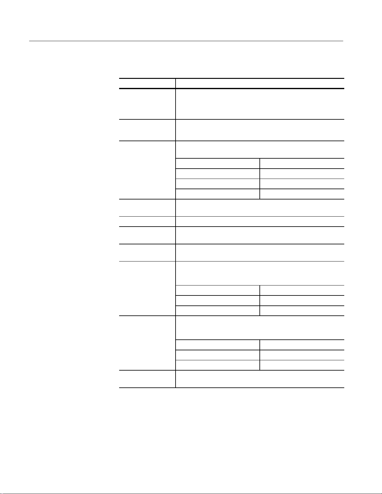
T able 1–1:
Description Characteristics
Number of input
channels
Number of small sampling module
compartments
Number of large sampling module
compartments
Small Sampling Module Interface
Large Sampling Module Interface
1
System – Signal acquisition
8 acquisition channels, maximum
4 compartments, for a total of 8 channels
2 compartments, for a total of 2 channels
Tekprobe-Sampling Level 3. Hot switching is not permitted on this
interface.
Tekprobe-Sampling Level 3. Hot switching is not permitted on this
interface.
Total channels ≤ 8.
1
1
CSA8000 & TDS8000 Instruments and Sampling Modules
1–1
Page 25
System Specifications
T able 1–2:
System – Timebase
Description Characteristics
Sampling rate DC-200 kHz maximum, dictated by trigger rate and actual holdoff
setting. If trigger rate is less than the maximum, or the requested
holdoff exceeds the minimum, the trigger rate and/or holdoff will dictate
the sampling rate.
Record length
Horizontal scale
range
1
20, 50, 100, 250, 500, 1000, 2000 and 4000 samples.
1 ps/div to 5 ms/div in 1, 2, 5 steps or 1 ps increments. Maximum
record lengths apply at certain ranges (per table, below).
Scale set to an integer multiple of: Maximum record length
1 ps/div 1000
2 ps/div 2000
4 ps/div 4000
Horizontal position
50 ms maximum.
range
Horizontal resolution 10 fs minimum
Horizontal position
1 ps minimum
setting resolution
Horizontal modes
2
Two modes, Short Term Optimized and Locked to 10 MHz Reference.
The 10 MHz reference may be internal or external.
n Time internal accuracy , short term
optimized mode
Strobe placement accuracy for a given horizontal interval and position
on same strobe line per table below. (Contribution from 80E04
sampling module is included in specification.)
Range Time Interval Accuracy
≤ 20 ps/div 1 ps + 1% of interval
≥ 21 ps/div 8 ps + 0.1% of interval
n Time internal accuracy , locked to internal 10 MHz reference mode
2
Strobe placement accuracy for a given horizontal interval and position
on same strobe line per table below. Contribution from 80E04 sampling
module is included in specification.
Range Time Interval Accuracy
≤ 20 ps/div 1 ps + 1% of interval
≥ 21 ps/div 8 ps + 0.01% of interval
Horizontal deskew
–500 ps to +100 ns on any individual channel in 1 ps increments.
range and resolution
1
The total number of samples contained in a single acquired waveform record
(memory length in IEEE 1057, 2.2.1).
2
80E02 sampling module is included in this specification.
1–2
CSA8000 & TDS8000 Instruments and Sampling Modules
Page 26

System Specifications
T able 1–3:
System – Trigger
Description Characteristics
Trigger sources External Direct Edge Trigger, External Precsaled Trigger, Internal Clock
Trigger, and Clock Recovery (with appropriately equipped optical
modules)
Auto/normal mode Normal mode: wait for trigger
Auto mode: Trigger automatically generated after 100 ms time-out
Slope + or – select Edge + mode: Triggers on positive-slewing edge
Edge – mode: Triggers on negative-slewing edge
High frequency on/off
select
High Frequency ON mode: Removes trigger hysteresis and improves
sensitivity. Should be used when trigger slew rate exceeds 1 V/ns.
High Frequency OFF mode: Retains trigger hysteresis and improves
noise rejection at low slew rates.
Metastability Reject
On/Off select
Metastability Reject On mode: Upon detection of trigger and holdoff
collision, time base will reject the sampled point.
Metastability Reject Off mode: Allows metastable points caused by
trigger/holdoff collisions to display.
Variable trigger hold
off range and resolution
External direct trigger
capabilities and
conditions
Adjustable 5 ms to 50 ms in 0.5 ns increments. When External
Prescaled Trigger mode is used, holdoff period applies to the Prescaled
circuit output.
Direct edge triggering on signal applied to dedicated front panel
connector with Holdoff, Level Adjust, Auto/Normal, High Frequency
On/Off, and Enhanced Triggering On/Of f controls.
External direct trigger
input characteristics
External direct trigger
input range
External direct trigger
maximum operating
trigger signal
2
External direct trigger
level range
n External direct
trigger sensitivity
3
External direct
trigger sensitivity
External direct trigger
level resolution
External direct trigger specifications apply only under the condition that
no other trigger signal is applied to respective connectors.
Short term optimized mode and locked to internal 10 MHz reference
specifications only apply under the condition that there is no external
10 MHz reference applied to the front panel connector.
50 W input resistance, DC coupled only
1
±1.5 V (DC + peak AC) maximum input voltage
1 Vpp
Adjustable between ±1.0 V
100 mV , DC-3 GHz
50 mV typical, DC-4 GHz
1 mV
CSA8000 & TDS8000 Instruments and Sampling Modules
1–3
Page 27

System Specifications
T able 1–3:
Description Characteristics
n External direct
trigger level accuracy
n External direct
trigger delay jitter,
short term optimized
mode
External direct trigger
delay jitter, short term
optimized mode (typical)
n External direct
delay jitter, locked to
internal 10 MHz reference mode
External direct delay
jitter, locked to internal 10 MHz reference
mode (typical)
External direct trigger
minimum pulse width
External direct trigger
metastability
External direct trigger
real time accessory
interface
External prescaled
trigger capabilities
System – Trigger (Cont.)
50 mV + 0.10 x level
1.5 ps RMS + 10 ppm of horizontal position, or better
1.0 ps RMS + 5 ppm of horizontal position, typical
2.5 ps RMS + 0.10 ppm of horizontal position, or better
1.6 ps RMS + 0.05 ppm of horizontal position, typical
167 ps, typical
Metastability Reject on: Zero, typical
Tekprobe-SMA, Levels 1 and 2. Hot switching is permitted on this real
time accessory interface.
Prescaled triggering on signal applied to dedicated front panel
connector with Holdoff, Auto/Normal, Metastability Reject On/Off.
1–4
External prescaled trigger specifications apply only under the condition
that no other trigger source is applied to respective connectors.
Short term optimized mode and locked to internal 10 MHz reference
specifications only apply under the condition that there is no external
10 MHz reference applied to the front panel connector.
External prescaled
trigger input characteristics
External prescaled
trigger absolute maximum input
n External prescaled The limits are as follows:
trigger sensitivity
50 W AC coupled input resistance; divide-by-eight prescaler ratio, fixed
level zero volts
2.5 Vpp
Frequency range
2-3 GHz 800 mV
3-10 GHz 600 mV
CSA8000 & TDS8000 Instruments and Sampling Modules
Sensitivity
pp
pp
Page 28

System Specifications
T able 1–3:
System – Trigger (Cont.)
Description Characteristics
External prescaled Frequency range Sensitivity
trigger sensitivity (typical)
n External prescaled
10-12.5 GHz
1.5 ps RMS + 10 ppm of horizontal position, or better
1000 mVpp, typical
trigger delay jitter,
Short term optimized
mode
External prescaled
1.0 ps RMS + 5 ppm of horizontal position, typical
trigger delay jitter,
Short term optimized
mode (Typical)
n External prescaled
2.5 ps RMS + 0.10 ppm of horizontal position, or better
delay jitter, locked to
internal 10 MHz reference mode
External prescaled
1.6 ps RMS + 0.05 ppm of horizontal position, typical
delay jitter, locked to
internal 10 MHz reference mode (Typical)
External prescaled
Enhanced Triggering, Metastability Reject on: Zero, typical
trigger metastability
Internal clock trigger
rates
Rate selectable at 25, 50, 100, and 200 kHz internally and is provided
to the trigger, to the TDR stimulus drives in the small sampling module
interfaces, and to the Internal Clock Out connector on the front panel.
1
The input resistance at the external direct trigger input and the maximum input
voltage.
2
Maximum signal input for maintaining calibrated time base operation.
3
Section 4.10.2 in IEEE standard number 1057. The minimum signal levels required
for stable edge triggering of an acquisition.
CSA8000 & TDS8000 Instruments and Sampling Modules
1–5
Page 29

System Specifications
T able 1–4: System – Environmental
Description Characteristics
Dynamics Random vibration (operating):
0.10 g rms, from 5 to 500 Hz, 10 minutes each axis, (3 axis,
30 minutes total) operating.
Random vibration (nonoperating):
2.00 g rms, from 5 to 500 Hz, 10 minutes each axis, (3 axis,
30 minutes total) non-operating.
Atmospherics Temperature:
Operating:
10 °C to +40 °C
Nonoperating:
–22 °C to +60 °C
Relative humidity:
Operating: 20% to 80%, with a maximum wet bulb temperature
of 29 °C at or below +50 °C (upper limits derates to 25% relative
humidity at +50 °C, non-condensing)
Nonoperating (no floppy disk in floppy drive): 5% to 90%, with a
maximum wet bulb temperature of 29 °C at or below +60 °C (upper
limits derates to 20% relative humidity at +60 °C, non-condensing)
Altitude:
Operating: 3,048 m (10,000 ft.)
Nonoperating: 12,190 m (40,000 ft.)
Electrostatic discharge susceptibility
Up to 8 kV with no change to control settings, or impairment of normal
operation
Up to 15 kV with no damage that prevents recovery of normal operation
T able 1–5: CSA8000 and TDS8000 – Power consumption and cooling
Specifications Characteristics
Power requirements 600 watts
Cooling requirements Six fans with speed regulated by internal temperature sensors.
A 2” (51 mm) clearance must be maintained on the bottom, left side,
and right side of the instrument for forced air flow. It should never be
operated on a bench with the feet removed, nor have any object placed
nearby where it may be drawn against the air vents.
1–6
No clearance is required on the front, back, and top.
CSA8000 & TDS8000 Instruments and Sampling Modules
Page 30
System Specifications
T able 1–6: CSA8000 and TDS8000 – Display
Specifications Characteristics
Display type 211.2 mm (wide) x 1.58.4 mm (high), 264 mm (10.4 inch) diagonal,
liquid crystal active matrix color display (LCD).
Display resolution 640 horizontal by 480 vertical pixels.
Pixel pitch Pixels are 0.33 mm (horizontal) and 0.22 mm (vertical)
T able 1–7: CSA8000 and TDS8000 – Ports
Specifications Characteristics
Video outputs Two 15-pin D-subminiature connectors on the rear panel. Useable to
connect external monitors that provide a duplicate of the primary and/or
a second monitor on which to view other applications. Support at least
the basic requirements of the PC99 specification.
Parallel port
(IEEE 1284)
25-pin D-subminature connector on the rear panel. Supports the
following modes:
Standard mode, output only
Bi-directional, PS/2 compatible
Bi-directional Enhanced Parallel Port (IEEE 1284 standard, Mode 1 or
Mode 2, v1.7
Bi-directional high speed Extended Capabilities Port (ECP)
Serial Port 9-pin D-subminature serial port connector using NS16C550 compatible
UARTs supporting transfer speeds up to 115.2 kbits/sec.
PS/2 Keyboard and
Mouse Interface
LAN interface RJ-45 LAN connector supporting 10 base-T and 100 base-T
External audio con-
nectors
USB interface One USB connector (the second USB is disable because of internal
GPIB interface Complies with IEEE 488.2
Interal clock trigger
out
PS/2 compatible keyboard and mouse connectors.
External audio jacks for MIC IN and LINE OUT
use)
Square wave out from 50 W, back termination synchronized to the TDR
internal clock drive signal, Refer to Trigger System–Internal Clock.
Typical performance into 50 W termination:
–0.20 to +0.20 V low level
CSA8000 & TDS8000 Instruments and Sampling Modules
–0.90 to +1.10 V high level
1–7
Page 31

System Specifications
T able 1–7: CSA8000 and TDS8000 – Ports (Cont.)
Specifications Characteristics
DC calibration output DC voltage from low impedance drive, programmable to 1 mV over
1.25 V range maximum. Accuracy is 0.1 mV +0.1%
External 10 MHz reference input
5 V maximum
T able 1–8: CSA8000 and TDS8000 – Data storage
Specifications Characteristics
Floppy disk drive 3.5 in floppy disk, 1.44 Mbyte, compatable with DOS 3.3 or later format
for storing reference waveforms, image files, and instrument setups.
Hard disk drive capacity
6 Gbytes
T able 1–9: CSA8000 and TDS8000 – Mechanical
Specifications Characteristics
Construction material Chassis: Aluminum alloy
Cosmetic covers: PC/ABS thermoplastic
Front panel: Aluminum alloy with PC/thermoplastic overlay
Module doors: Nickel plated stainless steel
Bottom cover: Vinyl clad sheet metal
Circuit boards: Glass-laminate.
Cabinet: Aluminum.
Weight 20.8 kg (45 lb. 12 oz.)
Overall Dimensions Height 343 mm (13.5 in.)
Width 457 mm (18.0 in.)
Depth 419 mm (16.5 in.)
The dimensions do not include feet, rack mount kit, or protruding
connectors.
Overall mass, pack-
aged product
Overall Dimensions,
packaged product
36.3 kg (80 lb. 1 oz.)
Height 622 mm (24.5 in.)
Width 71 1 mm (28.0 in.)
Depth 787 mm (31.0 in.)
1–8
CSA8000 & TDS8000 Instruments and Sampling Modules
Page 32

Certifications
T able 1–10: Certifications and compliances
Category Standards or description
System Specifications
EC Declaration of Conformity –
EMC
Meets intent of Directive 89/336/EEC for Electromagnetic Compatibility when configured with
sampling head modules designed for use with this instrument as identified in this manual.
Compliance was demonstrated to the following specifications as listed in the Official Journal of the
European Union:
EN 61326 EMC Requirements for Electrical Equipment for Measurement,
Control and Laboratory use.
Class A Radiated and Conducted Emissions
IEC 1000-4-2 Performance Criterion B
IEC 1000-4-3 Performance Criterion A
IEC 1000-4-4 Performance Criterion B
IEC 1000-4-5 Performance Criterion B
IEC 1000-4-6 Performance Criterion A
IEC 1000-4-11 Performance Criterion B
1
Performance Criteria C for USB keyboard and mouse. Note that operation of the
1,2
1
1
1
1
1
USB keyboard and mouse can be restored by unplugging and then
reconnecting the USB connector at the rear panel of the main instrument.
2
Horizontal timing susceptibility of the optical sampling modules and their
internal clock recovery trigger signals usually increase the horizontal timing
jitter when external electromagnetic fields are applied. For fields up to 3 V/m,
the increase in the horizontal high-frequency RMS jitter is typically less than
3 ps RMS of jitter, added using the square-root-of-the-sum-of-the-squares
method. An example follows:
If an 80C01-CR operating in clock-recovery trigger mode exhibits 3.5 ps RMS of
edge jitter, with no EMC field applied and for an ideal jitterless input, then for
applied fields up to 3 V/m the edge jitter, degradation would typically result in a
total RMS jitter of:
Jitter v 3.5ps
Ǹ
2
) 3ps
2
+ 4.61ps
EN 61000-3-2 AC Power Harmonic Current Emissions
Radiated emissions may exceed the levels specified in EN 61326 when this instrument is connected
to a test object.
Australia/New Zealand
Declaration of Conformity –
Complies with EMC Framework per the following standard:
AS/NZS 2064.1/2 Class A Radiated and Conducted Emissions
EMC
General EMC To ensure compliance with EMC requirements, only high quality shielded cables having a reliable,
continuous outer shield (braid & foil) with full coverage, low impedance connections to shielded
connector housings at both ends should be connected to this product.
EC Declaration of Conformity –
Low Voltage
Compliance was demonstrated to the following specification as listed in the Official Journal of the
European Union:
Low Voltage Directive 73/23/EEC, amended by 93/69/EEC
CSA8000 & TDS8000 Instruments and Sampling Modules
1–9
Page 33

System Specifications
T able 1–10: Certifications and compliances (cont.)
Category Standards or description
EN 61010-1/A2:1995 Safety requirements for electrical equipment for measurement
U.S. Nationally Recognized
Testing Laboratory Listing,
mainframe
Canadian Certification,
mainframe
UL3111-1 Standard for electrical measuring and test equipment.
CAN/CSA C22.2 No. 1010.1 Safety requirements for electrical equipment for measurement,
control and laboratory use.
control, and laboratory use.
Installation (Overvoltage)
Category
Pollution Degree A measure of the contaminates that could occur in the environment around and within a product.
Safety Certification Compliance
Equipment Type T est and measuring
Safety Class Class 1 (as defined in IEC 1010-1, Annex H) – grounded product
Overvoltage Category Overvoltage Category II (as defined in IEC 1010-1, Annex J)
Pollution Degree Pollution Degree 2 (as defined in IEC 1010-1). Note: Rated for indoor use only.
Terminals on this product may have different installation (overvoltage) category designations. The
installation categories are:
CA T III Distribution-level mains (usually permanently connected). Equipment at this level is
typically in a fixed industrial location.
CA T II Local-level mains (wall sockets). Equipment at this level includes appliances, portable
tools, and similar products. Equipment is usually cord-connected.
CA T I Secondary (signal level) or battery operated circuits of electronic equipment.
Typically the internal environment inside a product is considered to be the same as the external.
Products should be used only in the environment for which they are rated.
Pollution Degree 1 No pollution or only dry , nonconductive pollution occurs. Products in
this category are generally encapsulated, hermetically sealed, or
located in clean rooms.
Pollution Degree 2
Pollution Degree 3
Pollution Degree 4
Normally only dry, nonconductive pollution occurs. Occasionally a
temporary conductivity that is caused by condensation must be
expected. This location is a typical office/home environment.
Temporary condensation occurs only when the product is out of
service.
Conductive pollution, or dry, nonconductive pollution that becomes
conductive due to condensation. These are sheltered locations
where neither temperature nor humidity is controlled. The area is
protected from direct sunshine, rain, or direct wind.
Pollution that generates persistent conductivity through conductive
dust, rain, or snow. Typical outdoor locations.
1–10
CSA8000 & TDS8000 Instruments and Sampling Modules
Page 34

80E00 Electrical Sampling Modules
This section contains specifications for the 80E01, 80E02, 80E03, & 80E04
Sampling Modules. All specifications are guaranteed unless noted as “typical.”
Typical specifications are provided for your convenience but are not guaranteed.
Specifications that are marked with the n symbol are checked in Performance
Verification in the service manual.
All specifications apply to all models of sampling module unless noted
otherwise. To meet specifications, three conditions must first be met:
H The instrument must have been calibrated/adjusted at an ambient tempera-
ture between +20_ C and +30_ C.
H The oscilloscope must have been operating continuously for 20 minutes
within the operating temperature range specified.
H The instrument must be in an environment with temperature, altitude,
humidity, and vibration within the operating limits described in these
specifications
80E00 Modules Specifications
NOTE. “Sampling Interface” refers to both the electrical sampling module
interface and the optical module interface, unless otherwise specified.
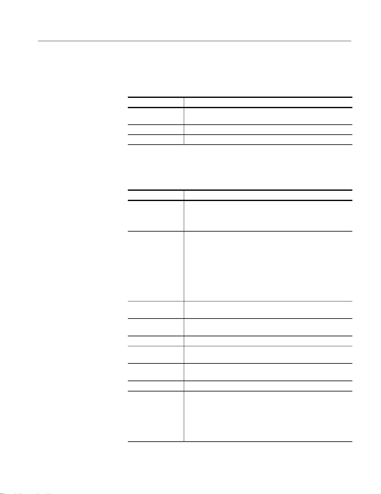
T able 1–11: Electrical sampling modules – Descriptions
Sampling module Description
80E01 1 channel 50 GHz/7 ps bandwidth, 50 W sampling module.
80E02 2 channel 12.5 GHz/28 ps bandwidth, 50 W, low noise sampling
module.
80E03 2 channel 20 GHz/17.5 ps bandwidth, 50 W sampling module.
80E04 2 channel 20 GHz/17.5 ps bandwidth, 50 W TDR/sampling module with
35 ps single ended, common mode, and differential TDR capability.
CSA8000 & TDS8000 Instruments and Sampling Modules
1–11
Page 35

80E00 Modules Specifications
T able 1–12: Electrical sampling modules – Signal acquisition
Specifications Characteristics
Real time accessory
interface
Channel input
connector
Number of input
channels
n Input impedance 50 W ±0.5 W
Vertical dynamic
range
Tekprobe-SMA interface is provided through the electrical samplingmodule interface, one per vertical channel.
80E02, 80E03, and 80E04: precision 3.5 mm connector.
80E01: precision 2.4 mm connector (2.4 mm male to 2.92 mm (K)
female adapter, 011-0157-xx, is supplied).
80E01: 1
80E02, 80E03, 80E04: 2
1 Vpp (offset "500 mV)
Vertical operating
1
, maximum
range
Vertical nondestruct
2
range
(Maximum Input
Voltage)
Vertical number of
digitized bits
Vertical sensitivity
3
range
Compensation
temperature range
n DC voltage
accuracy , single point,
within " 5_C of
compensated
temperature
n DC vertical
voltage deviation from
linear least squares
fit
n Rise time
4
±1.6 V
80E01: 2.0 V (DC+peak AC)
80E02, 80E03, 80E04: 3.0 V (DC+peak AC)
14 bits full scale
The range of available full scale input settings.
10 mV to 1 V full scale
"5_ C about temperature where compensation was performed. If
compartment is changed on the mainframe, a sampling module
extender is employed, or the length of the sampling module extender is
changed, the channel must be recompensated.
2 mV 0.007 (assigned offset)
0.02 (vertical value – assigned offset)
10 mV
Sampling module Rise time
80E01: 7 ps, typical (0.35 bandwidth-
risetime product)
80E02 ≤ 28 ps
80E03 and 80E04 ≤ 17.5 ps
1–12
CSA8000 & TDS8000 Instruments and Sampling Modules
Page 36

80E00 Modules Specifications
T able 1–12: Electrical sampling modules – Signal acquisition (Cont.)
Specifications Characteristics
n Analog bandwidth5Sampling module Bandwidth
80E01 50 GHz
80E02 12.5 GHz, typical
80E03 and 80E04 20 GHz, typical
Step response Sampling module Aberrations, step transition
aberrations6, typical
80E02, 80E03 and 80E04
±3% or less over the zone 10 ns
to 20 ps before step transition
+10%, –5% or less for the first
300 ps following step transition
±3% or less over the zone 300 ps
to 5 ns following step transition
±1% or less over the zone 5 ns to
100 ns following step transition
6
±0.5% after 100 ns following step
transition
80E01 ±3% or less over the zone 10 ns
to 20 ps before step transition
+12%, –5% or less for the first
300 ps following step transition
+5.5%, –3% or less over the zone
300 ps to 3 ns following step
transition
±1% or less over the zone 3 ns to
100 ns following step transition
±0.5% after 100 ns following step
transition
Random noise, Sampling module Noise, typical
displayed
80E01
80E02 400 mV
80E03 and 80E04 600 mV
1.8 mV
RMS
RMS
RMS
CSA8000 & TDS8000 Instruments and Sampling Modules
1–13
Page 37

80E00 Modules Specifications
T able 1–12: Electrical sampling modules – Signal acquisition (Cont.)
Specifications Characteristics
n Random noise, Sampling module Noise
displayed
80E01
80E02 ≤ 800 mV
80E03 and 80E04 ≤ 1.2 mV
Offset range
1
1
±1.6 V
Vertical operating range defines the maximum range over which the offset plus peak
input signal can operate. The offset may be limited as a function of vertical
sensitivity and dynamic range, such that no signal exceeding the maximum
operating range can be displayed.
2
Vertical nondestruct range defines the maximum range over which offset plus peak
input signal can operate without irreversible damage to the instrument. Operation to
instrument specification is not guarantied outside of the vertical operating range.
3
Input Signal Ranges in IEEE std 1057, section 2.2.1.
4
IEEE std 1057, section 4.8.2, Transition Duration of Step Response. Calculated from
0.35 bandwidth-risetime product.
5
IEEE std 1057, section 4.6, Analog Bandwidth.
6
IEEE std 1057, section 4.8.4, Overshoot and Precursors. Step transition occurs at the
point of minimum radius of the waveform curvature, after the 50% amplitude point of
the step leading edge.
≤ 2.3 mV
RMS
RMS
RMS
T able 1–13: Electrical sampling module (80E04) – TDR system
Specifications Characteristics
Number of TDR channels
TDR polarity and operation mode selections
Maximum input voltage
TDR amplitude 80E04: 250 mV each polarity, typical
80E04: 2, one per channel
80E04: Positive polarity, negative polarity, and TDR of f are
independently selectable for each channel.
80E04: Do not apply input voltage during TDR operation.
1–14
CSA8000 & TDS8000 Instruments and Sampling Modules
Page 38

80E00 Modules Specifications
n
T able 1–13: Electrical sampling module (80E04) – TDR system (Cont.)
Specifications Characteristics
n TDR system reflected rise time
1
TDR system incident
rise time
TDR step maximum
repetition rate
TDR system step 80E04 Aberrations, step transition
response aberrations
1
IEEE std 1057, section 4.8.2, transition duration of step response.
2
IEEE std 1057, section 4.8.4, overshoot and precursors.
80E04: ≤ 35 ps each polarity
80E04: 28 ps, typical
80E04: 200 kHz
2
2
2
±3% or less over the zone 10 ns to 20 ps before step transition
+10%, –5% or less typical for the first 400 ps following step transition
±3% or less over the zone 400 ps to 5 ns following step transition
±1% or less after 5 ns following step transition
T able 1–14: Electrical sampling modules – Timebase system
Specifications Characteristics
Sampling rate DC-200 kHz maximum.
Horizontal position
v19 ns, no extender cable present, external direct trigger operation.
range, minimum
(deskew adjust range
between channels)
T able 1–15: Electrical sampling modules – Power consumption
Specifications Characteristics
Power dissipation 80E01 1.1 W
80E02, 80E03 1.8 W
80E04 3.2 W
CSA8000 & TDS8000 Instruments and Sampling Modules
1–15
Page 39

80E00 Modules Specifications
T able 1–16: Electrical sampling modules – Mechanical
Specifications Characteristics
Weight 80E01, 80E02, 80E03, and 80E04 0.4 kg (13 oz.)
Overall dimensions Height: 25 mm (1.0 in)
Width: 79 mm (3.1 in)
Depth: 135 mm (5.3 in)
Does not include connectors, connector savers, connector covers, push
buttons, or lock-down hardware protruding from the front or rear panels.
Construction material Chassis aluminum alloy;
Front panel plastic laminate;
Circuit boards glass-laminate;
Cabinet sleeve aluminum
Cabinet end covers aluminum
1–16
CSA8000 & TDS8000 Instruments and Sampling Modules
Page 40

80C00 Optical Modules
This section contains specifications for the 80C01, 80C02, 80C03, 80C04,
80C05, and 80C06 Optical Sampling modules. All specifications are guaranteed
unless noted as “typical.” Typical specifications are provided for your convenience but are not guaranteed. Except for limits noted “typical,” specifications
that are marked with the n symbol are checked in the Performance Verification
section of the service manual.
All specifications apply to the 80C01, 80C02, 80C03, 80C04, 80C05, and
80C06 Optical Sampling modules unless noted otherwise. To meet specifications, three conditions must first be met:
H The instrument must have been calibrated/adjusted at an ambient tempera-
ture between +20_ C and +30_ C.
H The instrument must have been operating continuously for 20 minutes within
the operating temperature range specified.
80C00 Modules Specifications
H The instrument must be in an environment with temperature, altitude,
humidity, and vibration within the operating limits described in these
specifications
NOTE. “Sampling Interface” refers to both the electrical sampling module
interface and the optical module interface, unless otherwise specified.
T able 1–17: Optical modules – Descriptions
Name Characteristics
80C01 Long wavelength 1100 nm - 1650 nm. Unamplified O/E converter with
two user selectable optical bandwidths:
12.5 GHz,
u20 GHz, or
three user selectable reference receiver responses:
OC-12/STM-4 for 622.08 Mb/s Sonet/SDH standards,
OC-48/STM-16 for 2.488 Gb/s Sonet/SDH standards, and
OC-192/STM-64 for 9.953 Gb/s Sonet/SDH standards.
80C02 Long wavelength 1100 nm - 1650 nm. Unamplified O/E converter with
three user selectable optical bandwidths:
12.5 GHz
20 GHz,
u30 GHz, or
user selectable reference receiver response:
OC-192/STM-64 for 9.953 Gb/s Sonet/SDH standards.
CSA8000 & TDS8000 Instruments and Sampling Modules
1–17
Page 41

80C00 Modules Specifications
T able 1–17: Optical modules – Descriptions (Cont.)
Name Characteristics
80C03 Broad wavelength 700 nm - 1650 nm. Amplified O/E converter with
optical bandwidth of u2.5 GHz. The 2.5 Gb/s, OC-48/STM-16, and
2.5 GHz modes all use a physical path that has OC48/STM-16
reference receiver type response. Two other selectable reference
receiver responses: FC1063 for the 1.0625 Gb/s fibre channel standard
and GBE for the 1.25 Gb/s gigabit ethernet standard.
80C04 Long wavelength 1100 nm - 1650 nm. Unamplified O/E converter with
two user selectable optical bandwidths:
20 GHz,
u28 GHz,
or two user selectable reference receiver responses:
OC-192/STM-64 for 9.953 Gb/s Sonet/SDH standards
10.66 Gb/s for FEC10.664 Gb/s
80C05 Long wavelength 1520 nm - 1580 nm. Unamplified O/E converter with
maximum optical bandwidth (in combination with the internal electrical
sampler)u40 GHz. Calibrated only at 1550 nm.
There is one reference receiver setup selectable:
OC-192 for 9.95328 Gb/s Sonet/SDH standards
No clock recovery option available.
80C06 Long wavelength 1520 nm - 1580 nm. Unamplified O/E converter with
maximum optical bandwidth (in combination with the internal electrical
sampler)u50 GHz. It is calibrated only at 1550 nm. Fixed bandwidth
selection of 50 GHz. No reference receiver setups.
No clock recovery option available.
1–18
T able 1–18: Optical modules – Acquisition
Name Characteristics
Number of input
channels
Internal fiber Module Characteristics
diameter
Internal fiber
diameter
Fiber connector Rifocs UCI (universal connector interface)2 male connector
1
1
1 optical
80C01 9 mm/125 mm single mode
80C02 9 mm/125 mm single mode
80C03 62.5 mm (Corning 62.5/125 CPC6
specs) multimode (compatible
with single-mode fiber)
cladding: 125 mm,
buffer: 900 mm
80C04, 80C05 & 80C06 9 mm/125 mm single mode
CSA8000 & TDS8000 Instruments and Sampling Modules
Page 42

80C00 Modules Specifications
T able 1–18: Optical modules – Acquisition (Cont.)
Name Characteristics
Optical return loss Module Loss
80C01 u30 dB for single-mode fiber
80C02 u30 dB for single-mode fiber
80C03 u14 dB for multimode fiber
u24 dB for single-mode fiber
80C04, 80C05, and 80C06 u30 dB for single-mode fiber
Absolute maximum
nondestructive optical
2
input
Effective wavelength Module Range
range3, typical
80C01, 80C02, 80C03, and
80C04
80C05 10 mW average power, 30 mW
80C06 20 mW average power, 60 mW
80C01
5 mW average power, 10 mW
peak power at wavelength with
highest relative responsively.
peak power at wavelength with
highest relative responsively.
peak power at wavelength with
highest relative responsively.
1100 nm to 1650 nm
80C02 1100 nm to 1650 nm
80C03 700 nm to 1650 nm
80C04 1100 nm to 1650 nm
80C05 1520 nm to 1580 nm
80C06 1520 nm to 1580 nm
Calibrated Module Range
wavelengths
80C01
80C02 1550 nm and 1310 nm "20 nm
80C03 1550 nm, 1310 nm, 850 nm, and
80C04 1550 nm and 1310 nm "20 nm
80C05 & 80C06 1550 nm "20 nm
1550 nm and 1310 nm "20 nm
780 nm (all "20 nm)
CSA8000 & TDS8000 Instruments and Sampling Modules
1–19
Page 43

80C00 Modules Specifications
T able 1–18: Optical modules – Acquisition (Cont.)
Name Characteristics
n Dark level 80C01:
OC-12/STM-4,
OC-48/STM-16,
OC192/STM-64,
12.5 GHz settings: "[10 mW +2%|vertical offset|]
20 GHz settings: "[10 mW +4%|vertical offset|]
80C02:
OC192/STM-64,
12.5 GHz settings: "[10 mW +2%|vertical offset|]
20 GHz,
30 GHz settings: "[10 mW +4%|vertical offset|]
80C03:
All settings: "[500 nW +2%|vertical offset|]
80C04:
OC192/STM-64,
10.66 Gb/s settings: "[10 mW +2%|vertical offset|]
20 GHz,
30 GHz settings: "[10 mW +4%|vertical offset|]
80C05:
OC192 "[10 mW +2%|vertical offset|]
20 GHz settings; "[30 mW +4%|vertical offset|]
30 GHz settings; "[30 mW +4%|vertical offset|]
40 GHz settings; "[30 mW +4%|vertical offset|]
80C06:
50 GHz settings; "[25 mW +4%|vertical offset|]
Main-instrument
display vertical scale
factors
To achieve these levels, perform a dark level compensation, keep the
trigger rate and vertical offset the same as during the compensation,
and if the ambient temperature changes more than 1° C, perform
another dark level compensation.
Module Maximum Minimum
80C01: 1 mW per division 10 mW per division
80C02: 1 mW per division 10 mW per division
80C03: 100 mW per division 1 mW per division
80C03: 100 mW per division 1 mW per division
80C04: 1 mW per division 10 mW per division
80C05: 3 mW per division 30 mW per division
80C06: 6 mW per division 60 mW per division
Full scale vertical on the display of the main instrument is 10 divisions.
Maximum full scale and minimum full scale are therefore 10 times the
values listed above. Vertical scale is adjustable in a 1-2-5 sequence.
Between those settings, the scale can be adjusted in smaller
increments.
1–20
CSA8000 & TDS8000 Instruments and Sampling Modules
Page 44

T able 1–18: Optical modules – Acquisition (Cont.)
Name Characteristics
Vertical of fset range 80C01: "8 mW
80C02: "6 mW
80C03: "1 mW
80C04: "6 mW
80C05: "15 mW
80C06: "40 mW
DC vertical accuracy4,
typical
80C01
12.5 GHz,
OC-192/STM-64,
OC-48/STM-16,
OC-12/STM-4 settings:
"[25 mW +2% of [|vertical value – vertical offset|]
20 GHz setting:
"[25 mW +4% of [|vertical value – vertical offset|]
80C02
12.5 GHz:
"[25 mW +2% of [|vertical value – vertical offset|]
OC-192/STM-64:
"[25 mW +2% of [|vertical value – vertical offset|]
20 GHz setting:
"[25 mW +4% of [|vertical value – vertical offset|]
30 GHz setting:
"[25 mW +6% of [|vertical value – vertical offset|]
80C03, all settings:
"[25 mW +2% of [|vertical value – vertical offset|]
80C04
10.66 Gb/s:
"[25 mW +2% of [|vertical value – vertical offset|]
OC-192/STM-64:
"[25 mW +2% of [|vertical value – vertical offset|]
20 GHz setting:
"[25 mW +4% of [|vertical value – vertical offset|]
30 GHz setting:
"[25 mW +6% of [|vertical value – vertical offset|]
80C05
OC192:
"[25 mW +2% of [|vertical value – vertical offset|]
20 GHz setting:
"[25 mW +4% of [|vertical value – vertical offset|]
30 GHz setting:
"[25 mW +6% of [|vertical value – vertical offset|]
40 GHz setting:
"[25 mW +8% of [|vertical value – vertical offset|]
80C06
50 GHz setting:
"[25 mW +6% of [|vertical value – vertical offset|]
80C00 Modules Specifications
Valid for calibrated wavelengths and for user calibration.
CSA8000 & TDS8000 Instruments and Sampling Modules
1–21
Page 45

80C00 Modules Specifications
T able 1–18: Optical modules – Acquisition (Cont.)
Name Characteristics
DC vertical difference
accuracy
The accuracy of the
difference between
two cursors in the
vertical scale of the
same channel.
Offset capabilities Open loop. User assigned, fixed offset value applied to channel.
n Minimum optical
bandwidth
4
, typical
5
10.66 Gb/s, 12.5 GHz, OC-192/STM-64, OC-48/STM-16,
OC-12/STM-4 settings:
"2% of difference reading
20 GHz setting:
"4% of difference reading
30 GHz setting:
"6% of difference reading
80C03, all settings:
"2% of difference reading
80C05, 40 GHz setting:
"8% of difference reading
80C06, 50 GHz setting:
"2% of difference reading
Valid for calibrated wavelengths and for user calibration.
80C01 module, 20 GHz setting
12.5 GHz setting
80C02 module, 30 GHz setting
80C02-CR, 30 GHz setting
80C02 and 80C02-CR,
30 GHz setting
80C02, 20 GHz setting
80C02 CR, 12.5 GHz setting
80C03 module, 2.5 GHz setting u2.3 GHz, typical
80C04 module, 30 GHz setting
80C04-CR1, 80C04-CR2,
30 GHz setting
u20 GHz
u12.5 GHz
u30 GHz, typical
u29 GHz, typical
u28 GHz
u20 GHz
u12.5 GHz
u30 GHz, typical
u29 GHz, typical
1–22
80C04 & 80C04-CR1,
80C04-CR2, 30 GHz setting
80C04 20 GHz setting
80C05 module, 20 GHz setting
80C05 30 GHz setting
80C05 40 GHz setting
80C06 module, 50 GHz setting u50 GHz, typical
u28 GHz
u20 GHz
u20 GHz
u30 GHz
u40 GHz
CSA8000 & TDS8000 Instruments and Sampling Modules
Page 46

T able 1–18: Optical modules – Acquisition (Cont.)
m
m
Name Characteristics
Rise time, typical 80C01 module
For peak optical
signal input which
creates t2 mW
modulation depth,
except <200
for 80C03.
n Rise time, integrated, typical.
For optical signal input displaying 15 mW
peak impulse amplitude.
pp
Wpp
OC-12/STM-4 setting: 750 ps "50 ps
OC-48/STM-16 setting:
OC-192/STM-64 setting:
12.5 GHz setting:
20 GHz setting: t25 ps
80C02 module
30 GHz setting: t16 ps
20 GHz setting:
12.5 GHz setting:
OC-192/STM-64 setting:
80C03 module
FC1063 setting: 440 ps "35 ps
GBE setting:
OC-48/STM-16 setting:
80C04 module
30 GHz setting: t16 ps
20 GHz setting:
10.66 Gb/s setting:
OC-192/STM-64 setting:
80C05 module
20 GHz setting: t12 ps
30 GHz setting:
20 GHz setting:
OC-192 setting:
80C06 module
50 GHz setting: t9.6 ps
80C00 Modules Specifications
187 ps "15 ps
47 ps "10 ps
t40 ps
t25 ps
t40 ps
47 ps "10 ps
373 ps "30 ps
187 ps "15 ps
t25 ps
t44 ps "10 ps
47 ps "10 ps
t16 ps
t25 ps
47 ps "10 ps
CSA8000 & TDS8000 Instruments and Sampling Modules
1–23
Page 47

80C00 Modules Specifications
T able 1–18: Optical modules – Acquisition (Cont.)
Name Characteristics
Time domain vertical
response aberrations.
For peak optical
signal input
t5 mWpp, except:
80C03, t200 mWpp
80C01 OC-12/STM-4 setting: t5% all typical
OC-48/STM-16 setting: t5%
OC-192/STM-64 setting: t10%
12.5 GHz setting: t10%
20 GHz setting: t15%
80C02 OC-192/STM-64 setting: t10% all typical
12.5 GHz setting: t15%
20 GHz setting: t20%
30 GHz setting: t30%
80C03 All settings: t5% p-to-p typical
80C04 OC-192/STM-64 setting: t10% all typical
10.66 Gb/s setting: t10%
20 GHz setting: t20%
30 GHz setting: t30%
80C05 OC-192 setting: t5%, 2.5% typical
20 GHz setting: t10%, 5% typical
30 GHz setting: t10%, 5% typical
40 GHz setting: t15%, 10% typical
80C06 50 GHz setting: t10%, 5% typical
1–24
CSA8000 & TDS8000 Instruments and Sampling Modules
Page 48

80C00 Modules Specifications
T able 1–18: Optical modules – Acquisition (Cont.)
Name Characteristics
n Vertical equivalent 80C01 module Maximum RMS8Typical RMS
optical noise
7
OC-12/STM-4 setting: t12 mW
OC-48/STM-16 setting: t12 mW
OC-192/STM-64 setting: t12 mW
12.5 GHz setting: t12 mW
20 GHz setting: t25 mW
rms
rms
rms
rms
rms
t8 mW
t8 mW
t8 mW
t8 mW
t15 mW
rms
rms
rms
rms
80C01–CR module Maximum RMS8Typical RMS
OC-12/STM-4 setting: t15 mW
OC-48/STM-16 setting: t15 mW
OC-192/STM-64 setting: t15 mW
12.5 GHz setting: t15 mW
20 GHz setting: t25 mW
rms
rms
rms
rms
rms
t10 mW
t10 mW
t10 mW
t10 mW
t15 mW
80C02 module
OC-192/STM-64 setting: t10 mW
12.5 GHz setting: t10 mW
20 GHz setting: t15 mW
30 GHz setting: t30 mW
rms
rms
rms
rms
t6 mW
rms
t6 mW
rms
t10 mW
6
t20 mW
80C02–CR module
OC-192/STM-64 setting: t12 mW
12.5 GHz setting: t12 mW
20 GHz setting: t20 mW
30 GHz setting: t40 mW
rms
rms
rms
rms
t7 mW
rms
t7 mW
rms
t15 mW
6
t30 mW
80C03 & 80C03–CR modules
FC1063 setting: t1 mW
GBE setting: t1 mW
OC-48/STM-16 setting: t1.5 mW
rms
rms
rms
t0.75 mW
t0.75 mW
t1 mW
rms
80C04 module
OC-192/STM-64 setting: t10 mW
FEC 10.66 Gb/s setting: t10 mW
20 GHz setting: t15 mW
30 GHz setting: t30 mW
rms
rms
rms
rms
t6 mW
rms
t6 mW
rms
t10 mW
6
t20 mW
80C04–CR1 & 80C04–CR2 module
OC-192/STM-64 setting: t12 mW
FEC 10.66 Gb/s setting: t12 mW
20 GHz setting: t20 mW
rms
rms
rms
t7 mW
t7 mW
t15 mW
rms
rms
8
rms
8
rms
rms
rms
rms
rms
rms
rms
rms
rms
rms
rms
rms
rms
rms
CSA8000 & TDS8000 Instruments and Sampling Modules
1–25
Page 49

80C00 Modules Specifications
T able 1–18: Optical modules – Acquisition (Cont.)
Name Characteristics
n Vertical equivalent
optical noise
7
n Vertical equivalent 80C05 module Maximum RMS8Typical RMS
optical noise
7
n OC-12/STM-4
622 Mb/s Reference
Receiver setting
frequency response
30 GHz setting: t40 mW
OC-192 setting: t15 mW
20 GHz setting: t25 mW
30 GHz setting: t35 mW
40 GHz setting: t70 mW
rms
rms
rms
rms
rms
t30 mW
t10 mW
t15 mW
t25 mW
6
t50 mW
80C06 module Maximum RMS8Typical RMS
50 GHz setting: t192 mW
rms
t150 mW
In the 622.08 Mb/s NRZ setting, the scalar frequency response is
verified to fall within fourth-order Bessel-Thompson reference receiver
boundary limits.
6
The OC-12/STM-4 nominal scalar frequency response matches the
ITU 622.08 Reference Receiver Nominal curve with the following
tolerance:
rms
8
rms
rms
rms
rms
8
rms
(MHz) (dB)
Frequency Lower Nominal Upper
0.000 –0.50 0.00 0.50
93.3 –0.61 –0.11 0.39
186.6 –0.95 –0.45 0.05
279.9 –1.52 –1.02 –0.52
373.2 –2.36 –1.86 –1.36
466.7 –3.50 –3.00 –2.50
559.9 –5.67 –4.51 –3.35
622.1 –7.25 –5.71 –4.17
653.2 –8.08 –6.37 –4.66
746.5 –10.74 –8.54 –6.35
839.8 –13.55 –10.93 –8.31
933.1 –16.41 –13.41 –10.41
1244.2 –26.11 –21.45 –16.78
1–26
CSA8000 & TDS8000 Instruments and Sampling Modules
Page 50

T able 1–18: Optical modules – Acquisition (Cont.)
Name Characteristics
n OC48/STM-16
2.488 Gb/s Reference
Receiver setting
frequency response
Scalar frequency response falls within Industry Standard, BesselThompson reference receiver boundary limits.
SONET OC-48/STM-16 frequency response boundary limits are
6
described in ITU-T G.957 Tables I.1 and I.2. For convenience, the
scalar frequency response of the output amplitude (for sinusoidal swept
optical input) has been interpreted from the Bessel-Thompson transfer
function and listed below:
(MHz) (dB)
Frequency Lower Nominal Upper
0.000 –0.50 0.00 0.50
373.3 –0.61 –0.11 0.39
746.5 –0.95 –0.45 0.05
1119.7 –1.52 –1.02 –0.52
1493.1 –2.36 –1.86 –1.36
1866.3 –3.50 –3.00 –2.50
2239.5 –5.67 –4.51 –3.35
2488.3 –7.25 –5.71 –4.17
2612.8 –8.08 –6.37 –4.66
2986.0 –10.74 –8.54 –6.35
3359.3 –13.55 –10.93 –8.31
3732.6 –16.41 –13.41 –10.41
4976.7 –26.11 –21.45 –16.78
80C00 Modules Specifications
CSA8000 & TDS8000 Instruments and Sampling Modules
1–27
Page 51

80C00 Modules Specifications
T able 1–18: Optical modules – Acquisition (Cont.)
Name Characteristics
n OC192/STM-64
9.953 Gb/s Reference
Receiver setting
frequency response
Scalar frequency response falls within Industry Standard, BesselThompson reference receiver boundary limits.
Tektronix manufactures and tests the 80C01, 80C02, 80C04, and
6
80C05 optical modules using 10 GByte reference receivers to have a
new superior and tighter tolerance OC192/STM-64 Reference Receiver
response. ITU experts recently agreed on the minimum performance
specifications for 10 Gbit/s (STM-64/OC-192) optical reference
receivers (San Antonio ITU Study Group 15 February 2000). These
specifications are used to establish system interoperability and test
conformance of optical interfaces to draft ITU-T Recommendation
G.691 which is scheduled to be completed in April 200 (see ITU table
A.1/G.691 from the WD 16-48 document from Study Group 15 dated
February 2000). For convenience, the scalar frequency response of the
output amplitude (for sinusoidal swept optical input) has been
interpreted from the published Bessel-Thompson transfer function and
listed below:
(MHz) (dB)
Frequency Lower Nominal Upper
0.000 –0.85 0.00 0.85
1493.2 –0.96 –0.11 +0.74
2986.0 –1.30 –0.45 +0.40
4478.8 –1.87 –1.02 +0.17
5972.4 –2.71 –1.86 –1.01
7465.0 –3.86 –3.00 –2.16
8958.0 –6.19 –4.51 –2.83
9953.28 –7.87 –5.71 –3.55
10451.2 –8.75 –6.37 –3.99
11944.0 –11.53 –8.54 –5.56
13437.2 –14.45 –10.93 –7.41
14930.4 –17.41 –13.41 –9.41
1–28
CSA8000 & TDS8000 Instruments and Sampling Modules
Page 52

T able 1–18: Optical modules – Acquisition (Cont.)
Name Characteristics
n FEC 10.66 GByte
Reference Receiver
setting frequency
response
6
This Reference Receiver is essentially identical to that for the OC192
9.95328GByte/s rate with the following changes: the frequency scale
for the tolerance curves and nominal –3dB breakpoints are scaled
linearly by the ratio of (10.664 GByte/s)/(9.95328 GByte/s); for
example: the 9.953GByte/s reference receiver has a nominal –3dB
response at 0.75*9.95328GHz = 7.465GHz. This 10.66GByte reference
receiver has a nominal –3dB response at (10.664/9.95328)*7.465GHz
= 7.998GHz.
For convenience, the scalar frequency response of the output
amplitude (for sinusoidal swept optical input) has been interpreted from
the published Bessel-Thompson transfer function, the frequencies
scaled as described above, and then listed below:
(MHz) (dB)
Frequency Lower Nominal Upper
0 –0.85 0 0.85
1599.8 –0.96 –0.11 0.74
3199.2 –1.30 –0.45 0.40
4798.6 –1.87 –1.02 –0.17
6398.9 –2.71 –1.86 –1.01
7998.0 –3.86 –3.00 –2.16
9597.7 –6.19 –4.51 –2.83
10664.0 –7.87 –5.71 –3.55
11197.5 –8.75 –6.37 –3.99
12796.9 –11.53 –8.54 –5.56
14396.7 –14.45 –10.93 –7.41
15996.5 –17.41 –13.41 –9.41
80C00 Modules Specifications
CSA8000 & TDS8000 Instruments and Sampling Modules
1–29
Page 53

80C00 Modules Specifications
T able 1–18: Optical modules – Acquisition (Cont.)
Name Characteristics
n 2.50 Gb/s (2X
GBE) Reference
Receiver setting
frequency response
n GBE (1.25 Gb/s)
Reference Receiver
setting frequency
response
6
Scalar frequency response falls within Industry Standard, BesselThompson reference receiver boundary limits.
2.50 Gb/s frequency response boundary limits are derived by simply
6
scaling all frequency values by 2X as described in IEEE 802.3z section
38.6.5 (this section refers to ITU G.957 for tolerances). For convenience, the scalar frequency response of the output amplitude (for
sinusoidal swept optical input) has been interpreted from the
Bessel-Thompson transfer function and listed below:
(MHz) (dB)
Frequency Lower Nominal upper
0.000 –0.50 0.00 0.50
375 –0.61 –0.11 0.39
750 –0.95 –0.45 0.05
1125 –1.52 –1.02 –0.52
1500 –2.36 –1.86 –1.36
1875 –3.50 –3.00 –2.50
2250 –5.67 –4.51 –3.35
2500 –7.25 –5.71 –4.17
2625 –8.08 –6.37 –4.66
3000 –10.74 –8.54 –6.35
3375 –13.55 –10.93 –8.31
3750 –16.41 –13.41 –10.41
5000 –26.11 –21.45 –16.78
Scalar frequency response falls within Industry Standard, BesselThompson reference receiver boundary limits.
1.250 Gb/s frequency response boundary limits are described in IEEE
802.3z section 38.6.5 (this section refers to ITU G.957 for tolerances).
For convenience, the scalar frequency response of the output
amplitude (for sinusoidal swept optical input) has been interpreted from
the Bessel-Thompson transfer function and listed below:
1–30
(MHz) (dB)
Frequency Lower Nominal Upper
0.000 –0.50 0.00 0.50
187.5 –0.61 –0.11 0.39
375 –0.95 –0.45 0.05
562.5 –1.52 –1.02 –0.52
750 –2.36 –1.86 –1.36
937.5 –3.50 –3.00 –2.50
1125 –5.67 –4.51 –3.35
1250 –7.25 –5.71 –4.17
1312.5 –8.08 –6.37 –4.66
1500 –10.74 –8.54 –6.35
1687.5 –13.55 –10.93 –8.31
1875 –16.41 –13.41 –10.41
2500 –26.11 –21.45 –16.78
CSA8000 & TDS8000 Instruments and Sampling Modules
Page 54

80C00 Modules Specifications
T able 1–18: Optical modules – Acquisition (Cont.)
Name Characteristics
n FC1063
(1.0625 Gb/s)
Reference Receiver
setting frequency
response
1
2
6
Single-mode fiber (Corning SMF-28 specs).
The optical input powers below nondestructive levels may exceed saturation and
compression limits of the module.
3
The optical wavelengths that the product accepts optical inputs and still provides a
reasonable (25% of peak optimum) wavelength conversion gain.
4
Vertical accuracy specifications are referenced to the internal optical power meter
reading for a given optical input, and are limited to a temperature range within
"5_ C of previous channel compensation and an ambient temperature within 20_ C
to 35_ C.
5
Optical bandwidth is the frequency at which the responsivity of the optical to
electrical conversion process is reduced by 50% (6 dB).
6
This specification is limited to the instrument operating in an ambient temperature
between +20_ C and +30_ C. Nominal freq response is specified for optical input
signals of modulation magnitude such that 2 mW
signal is applied at the sampler input. for 80C05 at 40 GHz.
7
The optical channel noise with no optical noise input (Dark Level).
8
Clock recovery versions reduce the power reaching the vertical channel (splitter to
clock recovery produces loss). Therefore, the non-clock recovery modules more
closely exhibit the typical noise performance.
Scalar frequency response falls within Industry Standard, BesselThompson reference receiver boundary limits.
Fiber Channel frequency response boundary limits are described in
ANSI FC-PC. For convenience, the scalar frequency response of the
output amplitude (for sinusoidal swept optical input) has been
interpreted from the Bessel-Thompson transfer function and listed
below:
(MHz) (dB)
Frequency Lower Nominal Upper
0.000 –0.50 0.00 0.50
159.5 –0.61 –0.11 0.39
318.9 –0.95 –0.45 0.05
478.4 –1.52 –1.02 –0.52
637.9 –2.36 –1.86 –1.36
797.4 –3.50 –3.00 –2.50
956.8 –5.67 –4.51 –3.35
1063 –7.25 –5.71 –4.17
1116 –8.08 –6.37 –4.66
1275 –10.74 –8.54 –6.35
1435 –13.55 –10.93 –8.31
1595 –16.41 –13.41 –10.41
2126 –26.11 –21.45 –16.78
(200 uWpp for 80C03) or less
pp
CSA8000 & TDS8000 Instruments and Sampling Modules
1–31
Page 55

80C00 Modules Specifications
T able 1–19: Optical modules – Clock recovery option (CR)
Name Characteristics
Effective wavelength Module Range
range
80C01
80C02 1270 nm to 1600 nm
80C03 700 nm to 1650 nm
80C04 1270 nm to 1600 nm
Operating data rates 80C01: 622.08 MHz ±1000 ppm (OC-12/STM-4)
2.48832 GHz ±1000 ppm (OC-48/STM-16)
80C02: 9.95328 Gb/s "1000 ppm (OC-192/STM-64)
80C03: 1.0625 Gb/s "1000 ppm (FC1063)
1.2500 Gb/s "1000 ppm (GBE)
2.48832 Gb/s "1000 ppm (OC-48/STM-16)
2.5000 Gb/s "1000 ppm (2X GBE)
80C04-CR1: 9.95328 Gb/s "1000 ppm (OC-192/STM-64)
1270 nm to 1600 nm
nOptical sensitivity
range, clock recover
(optical input power)
Clock and data
electrical output
amplitudes
2
80C04-CR2: 9.95328 Gb/s "1000 ppm (OC-192/STM-64),
10.664 Gb/s "1000 ppm (FEC)
The incoming data stream must be of non-return-to-zero format (NRZ)
and, for OC-192/STM-64, must have a data sequence content which
provides both isolated 1s and multi-consecutive mark sequences (that
is 2,3,4 and so forth logical 1s in a consecutive row). NOTE: a fixed
pattern of 10101010. . . does not meet that requirement; the 80C02-CR
clock recovery function may not properly lock to such a pattern. The
80C02-CR will, however , typically lock to a 11001100. . . pattern (this
is equivalent to a 2.48832 GHz optical square wave).
Module Maximum Minimum
80C01 + 5.0 dBm (3.16 mW), typical –10.0 dBm (100 mW), typical
1
80C02 +7 dBm (5.0 mW), typical –10.0 dBm (100 mW), typical
–7.5 dBm, warranted
80C03 –4.0 dBm (400 mW), warranted –16.0 dBm (25 mW),
warranted
80C04 +7 dBm (5.0 mW), typical –10.0 dBm (100 mW), typical
–7.5 dBm, warranted
80C01: u300 mV
80C02 Serial DAT A output: u700 mV
Serial CLOCK output: 1.5 V
1/16th CLOCK output: 600 mV
80C03: u350 mV
80C04 Serial DAT A output: u700 mV
Serial CLOCK output: 1.5 V
1/16th CLOCK output: 600 mV
typical
pp,
pp,
typical
pp,
pp,
typical
pp,
typical
pp,
typical
typical
pp,
typical
pp,
typical
1–32
CSA8000 & TDS8000 Instruments and Sampling Modules
Page 56

80C00 Modules Specifications
T able 1–19: Optical modules – Clock recovery option (CR) (Cont.)
Name Characteristics
Clock and data rise
time and fall times
nRecovered clock
timing jitter
3, 4
Optical power meter
range
Optical power meter
accuracy , typical
80C01: t200 ps
2
80C02 Serial DAT A output: t30 ps
Serial CLOCK output: t30 ps
1/16th CLOCK output: t300 ps
80C03: t250 ps
80C04 Serial DAT A output: t30 ps
Serial CLOCK output: t30 ps
1/16th CLOCK output: t300 ps
80C01: t8.0 ps RMS maximum
t4.0 ps RMS typical
80C02: t2.0 ps RMS maximum
t1.0 ps RMS typical
5
80C03: t8.0 ps RMS maximum
t4.0 ps RMS typical
80C04: t2.0 ps RMS maximum
t1.0 ps RMS typical
5
80C01, 80C02, 80C03, 80C04:
+4 dBm to –30 dBm, typical
80C05:
+13 dBm to –21 dBm, typical
80C06:
+13 dBm to –21 dBm, typical
5% of reading + connector uncertainty, at the calibrated wavelengths.
See Table 1–18, page 1–18.
1
These powers are the average optical input coupled into the external Optical
Sampling Module optical input connector . The range is defined for recovered clock
and data with a resulting BER of 1x10
data (also referred to as 50% mark density), a PRBS pattern of 2
extinction ratio of w 8.2 dB (at eye center).
2
Output is 50 W AC coupled: specification is for output amplitude at the bulkhead
outputs and does not include RF loss of attached cables.
3
The clock jitter is applicable to both the external electrical output and the system
jitter experienced when the recovered clock is the source of the waveform trigger for
the system.
CSA8000 & TDS8000 Instruments and Sampling Modules
–10
or less, a 50% duty cycle of the incoming
23–1
, and an
1–33
Page 57

80C00 Modules Specifications
T able 1–19: Optical modules – Clock recovery option (CR) (Cont.)
Name Characteristics
4
Jitter performance of the system while using the optical module clock recovery as
the trigger source is warranted only while no active signal is applied to the main
instrument’s External Trigger (or Prescaler) input.
5
Internal use for trigger results in a total system jitter of
Ǹ
w sum of squares
therefore the displayed waveform may normally exhibit slightly more than 1 ps RMS
jitter.
T able 1–20: Optical modules – Mechanical
Name Characteristics
Construction material Chassis parts constructed of aluminum alloy; front panel constructed of
plastic laminate; circuit boards constructed of glass-laminate. Cabinet
is aluminum.
Weight 80C01: 1.13 kg (2.5 lbs)
80C01-CR: 1.34 kg (2.95 lbs)
80C02: 0.95 kg (2.1 lbs)
80C02-CR: 1.22 kg (2.70 lbs)
80C03: 1.13 kg (2.5 lbs)
80C03-CR: 1.34 kg (2.95 lbs)
80C04: 0.95 kg (2.1 lbs)
80C04-CR1: 1.22 kg (2.70 lbs)
80C04-CR2: 1.22 kg (2.70 lbs)
80C05: 1.22 kg (2.70 lbs)
80C06: 1.22 kg (2.70 lbs)
Overall dimensions Height: 25.6 mm (1.0 in)
Width: 166.7 mm (6.5 in)
Depth: 307.7 mm (12.0 in)
1–34
CSA8000 & TDS8000 Instruments and Sampling Modules
Page 58

T able 1–21: Optical modules – Environmental
Name Characteristics
Temperature Installed and operating:
10_ C to +40_ C
Reference receivers frequency response tolerances, 30 GHz mode,
and Optical power meter accuracy:
+20_ C to +30_ C
Installed and non-operating:
–22_ C to +60_ C
Humidity Installed and operating:
20% to 80% relative humidity with a maximum wet bulb temperature of
29_ C at or below +40_ C, (upper limit derates to 45% relative humidity
at +40_ C) non-condensing.
Reference receivers frequency response tolerances:
+20_ C to +30_ C
80C00 Modules Specifications
Optical power meter accuracy:
+20_ C (80% RH) to +30_ C (80% RH)
Installed and non-operating:
5% to 90% relative humidity with a maximum wet bulb temperature of
29_ C at or below +60_ C, (upper limit derates to 20% relative humidity
at +60_ C) non-condensing.
Altitude: installed Operating: 3,048 m (10,000 feet).
Non-operating: 12,190 m (40,000 feet)
CSA8000 & TDS8000 Instruments and Sampling Modules
1–35
Page 59

80C00 Modules Specifications
back
1–36
CSA8000 & TDS8000 Instruments and Sampling Modules
Page 60

80A01 Trigger Prescale Preamplifier Module
This section contains specifications for the 80A01 Trigger Prescale Preamplifier
Module. All specifications are guaranteed unless noted as “typical.” Typical
specifications are provided for your convenience but are not guaranteed.
To meet specifications, three conditions must first be met:
H The instrument must have been calibrated/adjusted at an ambient tempera-
ture between +20_ C and +30_ C.
H The oscilloscope must have been operating continuously for 20 minutes
within the operating temperature range specified.
H The instrument must be in an environment with temperature, altitude,
humidity, and vibration within the operating limits described in these
specifications
80A01 Module Specifications
The 80A01 Trigger Prescale Preamplifier module is a single-channel 8-14 GHz
AC coupled limiting preamplifier. It increases the trigger sensitivity of the 8000
Series instruments to v200 mV
up to 12.5 GHz (typical).
pk-pk
T able 1–22: Module characteristics
Specifications Characteristics
Mainframe interface Tekprobe-Sampling, Level 3. Hot switching is not permitted.
Input and output
connectors
Input power
Output power +10 dBm maximum saturation
Frequency Range 8 GHz to 14 GHz (typical)
80A01 Enhancement
toTrigger Sensitivity
Output voltage
Input/output
impedance
Input/output VSWR 2.0:1 maximum from 8-14 GHz (typical)
Power requirements 2.35 W
1
3
Female SMA
–10 dBm to +5 dBm, AC coupled
v200 mV System Prescale Trigger Sensitivity
8-12.5 GHz, input voltage 200 mV
12.5-14 GHz, input voltage 200 mV
50 W AC coupled (typical)
pk-pk
pk-pk
to 1 V
to 1 V
2
pk-pk
pk-pk
: w1 V
: w1 V
pk-pk
pk-pk
(typical)
CSA8000 & TDS8000 Instruments and Sampling Modules
1–37
Page 61

80A01 Module Specifications
T able 1–22: (Cont.)Module characteristics
Specifications Characteristics
Maximum input volt-
1.1 V
pk-pk
age swing
Noise figure 5 dB maximum
1
See Input Voltage Swing specification for more information.
2
The minimum level of signal applied to the input of an 80A01 that has its output
connected to the Trigger Prescale input of the main instrument. A coaxial cable
Tektronix part number 015-0560-00 is recommended for the connection from the
80A01 output to the Trigger Prescale input of the instrument.
3
Amplifier functions to 14 GHz but prescale trigger is nominally limited to 12.5 GHz
for 200 mVpk-pk sensitivity.
T able 1–23: Environmental specifications
Specification Characteristics
Temperature Operating: +10° C to +40° C
Humidity Non-operating: 5% to 90% relative humidity
Operating: 20% to 80% relative humidity
T able 1–24: Mechanical specifications
Specifications Characteristics
Weight 0.37 kg (13 oz.)
Overall dimensions Height: 24 mm (0.95 in)
Width: 74 mm (2.90 in)
Depth: 114 mm (4.95 in)
Does not include connectors, connector savers, connector covers, push
buttons, or lock-down hardware protruding from the front or rear panels.
Construction material Chassis aluminum alloy;
Front panel plastic laminate;
Circuit boards glass-laminate;
Cabinet sleeve aluminum
Cabinet end covers aluminum
1–38
CSA8000 & TDS8000 Instruments and Sampling Modules
Page 62

80A01 Module Specifications
T able 1–25: Electromagnetic specifications
Specification Characteristic
Emissions The instrument meets or exceeds the EMC requirements of the
following standards: Emissions European Community Requirements
(including EN 61326)
EN5501 1 Class A Radiated Emissions
EN5501 1 Class A Conducted Emissions
IEC 1000–3–2 Power Harmonic Current Emissions
Susceptibility The instrument meets or exceeds the EMC requirements of the
following standards:
EN61326–1 European Community Requirements
IEC 1000–4–2 Electrostatic Discharge Immunity
4 kV contact discharge
8 kV air discharge
Performance criteria B
CSA8000 & TDS8000 Instruments and Sampling Modules
1–39
Page 63

80A01 Module Specifications
1–40
CSA8000 & TDS8000 Instruments and Sampling Modules
Page 64

Page 65

Installation
NOTE. The information found in this section is a subset of the Installation
section found in the CSA8000 & TDS8000 User manual.
This section covers installation of the instrument, addressing the following
topics:
H Check the Environment Requirements on page 2–1
H Install the Sampling Modules on page 2–2
H Connect the Peripherals on page 2–4
H Power On the Instrument on page 2–5
H Powering Off the Instrument on page 2–7
The basic operating software is already installed on the hard disk. If reinstallation of software becomes needed, see the following topic:
H Software Installation on page 2–7
Check the Environmental Requirements
Read this section before attempting any installation procedures. This section
describes site considerations, power requirements, and ground connections for
your instrument.
Site Considerations
The instrument is designed to operate on a bench or on a cart in the normal
position (on the bottom feet). For proper cooling, at least two inches (5.1 cm) of
clearance is recommended on the rear and sides of the instrument.
You can also operate the instrument while it rests stood up on its rear feet. If you
operate the instrument while it is resting on the rear feet, make sure that you
properly route any cables coming out of the rear of the instrument to avoid
damaging them.
CAUTION. Keep the bottom of the instrument clear of obstructions to ensure
proper cooling.
CSA8000 & TDS8000 Instruments and Sampling Modules
2–1
Page 66

Installation
Operating Requirements
Rackmount Requirements
Specifications in chapter 1 list the operating requirements for the instrument.
Power source and temperature, humidity, and altitude are listed.
If this instrument is rackmounted, see the TDS8000 & CSA8000 Rackmount
Instructions for additional site considerations or operating requirements. This
document ships with the Option 1 R (rackmount kit).
Install the Sampling Modules
CAUTION. Do not install or remove any sampling modules while the instrument is
powered on.
Always power the instrument down before attempting to remove or insert any
sampling module.
WARNING. Sampling modules are inherently vulnerable to static damage. Always
observe static-safe procedures and cautions as outlined in your sampling module
user manual.
Check Your Sampling
Module Manual(s)
The sampling modules that you order with your instrument ship with the
appropriate sampling-module user manuals. Read these manuals for instructions
on how to install your sampling modules, and then install them as outlined.
(Sampling modules do not ship preinstalled.)
NOTE. To find sampling module user manuals, check in the appendices of the
CSA8000 & TDS8000 User Manual if user documentation is available. Users
are instructed to insert their sampling-module user manuals there.
NOTE. After first installing a sampling module(s) or after moving a sampling
module from one compartment to another, you should run compensation from the
Utilities menu to ensure the instrument meets its accuracy specifications. You
must run a compensation (accessed from the Utilities menu) whenever the
extender configuration is changed from that present at the last compensation. In
short, if you install or remove an 80E00 extender, run a compensation. If you
exchange a extender for one of a different length, run a compensation. For
instructions on running a compensation, see Perform the Compensation on
page 4–5.
2–2
CSA8000 & TDS8000 Instruments and Sampling Modules
Page 67

Large-module compartments (2)
Small-module compartments (4)
Connect ESD wrist strap here
Installation
Figure 2–1 shows compartments for both large and small sampling modules,
along with the plug-in connector for the ESD wrist strap that you must use to
install these modules.
Figure 2–1: Compartments for sampling modules
Maximum Configuration
Eight channels: Two large modules and
three small modules
Eight channels: No large and four
small modules
Seven channels: One large module,
installed in either compartment,
and three small modules
You can install up to two large sampling modules and four small modules for a
total of 10 inputs. Of these 10 inputs, only eight inputs can be active at one time
(see Figure 2–2, top two configurations). Also, note that installing a single large
module in either compartment disables the first small-module compartment. This
configuration (see Figure 2–2, bottom configuration) limits the input count to
seven—one from the large, six from the small compartments.
CH 1 CH 2
1
N.A.
N.A.
CH 1 CH 2 CH 6CH 3 CH 8CH 5 CH 7
CH 1/N.A.
N.A. CH 6CH 3 CH 5 CH 7N.A. CH 4
CH 4
CH 6CH 3 CH 8CH 5 CH 7N.A. CH 4
N.A.
CH 2/N.A.
CH 8
1
Not Available
Figure 2–2: Maximum inputs in three configurations
Install probes, cables, and other connection accessories to your sampling
modules as appropriate for your application and sampling module. Again,
CSA8000 & TDS8000 Instruments and Sampling Modules
2–3
Page 68

Installation
Connect the Peripherals
consult your sampling-module and connection-accessory manuals. Continue with
the next section after installing the sampling modules.
The peripheral connections are mostly the same as those you would make on a
personal computer. The connection points are shown in Figure 2–3. See
Table 2–1 on page 2–4 for additional connection information.
WARNING. Before installing peripheral accessories to connectors (mouse, keyboard,
etc.), power down the instrument. See Powering Off the Instrument on page 2–7.
T able 2–1: Additional accessory connection information
Item Description
Monitor If you use a non-standard monitor, you may need to change the
the Windows-98 display settings to achieve the proper
resolution for your monitor.
Printer Connect the printer to the EPP (enhanced parallel port)
connector directly. If your printer has a DB-25 connector, use
the adapter cable that came with your printer to connect to the
EPP connector.
Rackmount Refer to the CSA8000 & TDS8000 Rackmount Installation
Instructions for information on installing the rackmount kit.
Other Refer to the Application release notes (readme.txt) in the
C:\Program Files\TDSCSA8000\System directory of the
instrument for possible additional accessory installation
information not covered in this manual.
2–4
CSA8000 & TDS8000 Instruments and Sampling Modules
Page 69

Description..........................Icon/Label Locations
Monitor.........
Printer..................
RS-232................
Network...........................
1
PS2 mouse
...............................
Installation
PS2 keyboard
USB...........................
Audio line out...........................
Audio line in........................
Removable hard drive........................
CD drive.........................
GPIB.....
Monitor...................
Card slot...........
1
Product ships with a USB keyboard, that plugs into the USB port, and a USB mouse that plugs into the back of the keyboard
1
..................
Figure 2–3: Locations of peripheral connectors on rear panel
Power On the Instrument
Follow these steps to power on the instrument for the first time.
1. Check that the line fuses are correct for your application. Both fuses must be
the same rating and type. Fuse types require a unique cap and fuseholder. See
Table 2–2 and Figure 2–4.
CSA8000 & TDS8000 Instruments and Sampling Modules
2–5
Page 70

Installation
T able 2–2: Line fuses
Cap & fuseholder
Fuse type Rating Fuse part number
0.25 x 1.250 inch 8 A, fast blow, 250 V 159-0046-00 200-2264-00
5 x 20 mm 6.3 A, fast blow, 250 V 159-0381-00 200-2265-00
Fuses AC PowerPower Switch
part number
Figure 2–4: Line fuse and power cord connector locations, rear panel
CAUTION. Connect the keyboard, mouse, and other accessories before applying
power to the product. Connecting the accessories after powering on the
instrument can damage the accessories. Two exceptions are the USB keyboard
and mouse that ships with the instrument. Both can be plugged or unplugged
without first turning power off.
2. Connect the keyboard and mouse, observing the caution above. Note that the
instrument ships with a USB keyboard, which plugs into the USB port (see
Figure 2–3 on page 2–5 for location) and a USB mouse, which plugs into
the back of the USB keyboard.
NOTE. Connection of the keyboard and mouse is optional. You can operate most
features without them, using the front-panel controls and the touchscreen.
3. Connect the power cord.
4. If you have an external monitor, connect the power cord and power on the
monitor.
5. Turn the Power switch on at the rear panel. (See Figure 2–4 on page 2–6 for
switch location.)
2–6
6. Push the On/Standby switch to power on the instrument (see Figure 2–5 for
the switch location).
CSA8000 & TDS8000 Instruments and Sampling Modules
Page 71

Switch
Installation
Figure 2–5: On/Standby switch location
7. Wait for the boot routine and low-level self test to complete.
8. Follow any instructions on the screen.
The internal setup software will automatically configure your instrument and
install all required devices, depending on the installed accessories.
Powering Off the Instrument
The instrument has a built-in soft power-down function that safely powers down
the instrument when you push the On/Standby button. You do not need to close
the UI application or Windows 98 before using the On/Standby button.
To completely remove power to the instrument, first soft power-down the
instrument using the On/Standby button, and then set the power switch on the
rear panel to off.
You can restore the UI application to the screen by clicking its button in the
Windows Task bar.
Software Installation
This section describes how to install the system software found on the CSA8000
& TDS8000 System Rebuild CD that accompanies this product. The instrument
ships with the product software installed, so only perform these procedures if
reinstallation becomes necessary.
Description
The product software comprises two parts:
H Window 98. Windows 98 comes preinstalled on the instrument. Windows 98
is the operating system on which the user-interface application of this
CSA8000 & TDS8000 Instruments and Sampling Modules
2–7
Page 72

Installation
product runs. The System Rebuild CD, which can be used to rebuild the
instrument hard drive, includes the Window 98 operating system installation.
If you need to reinstall Windows 98, you may be able to do so without rebuilding the instrument hard drive. See Operating System Reinstallation on page 2–8 for more information.
H User Interface (UI) Application. The UI application complements the
hardware controls of the front panel, allowing complete set up of all
instrument features. The System Rebuild CD includes the UI application
installation as part of a complete hard drive rebuild.
Software Release Notes
Operating System
Reinstallation
Read the software release notes README.TXT ASCII file if present on the
System Rebuild CD before performing any installation procedures. This file
contains additional installation and operation information that supercedes other
product documentation.
To view the README.TXT file, open the Notepad Windows accessory and open
the file on the System Rebuild CD. After installation, you can also read the copy
from a directory on the product:
C:\Programs Files\TDSCSA8000\System
Use the following procedure if reinstalling Windows 98 becomes necessary.
NOTE. Only do the reinstall if Windows 98 is missing or corrupted.
There are two possibilities for reinstall:
H The instrument can reboot from the hard drive; if so, reinstall windows using
the emergency startup disk and the procedure Windows 98 Reinstall Only on
page 2–8.
H The instrument cannot reboot from the hard drive or you do not have an
emergency startup disk available. In either case, you must rebuild your hard
drive using the procedure System Hard Drive Rebuild on page 2–9. Any
files or programs you have installed will be lost.
2–8
Windows 98 Reinstall Only. If you can reboot from the instrument hard drive and
you have your emergency startup disk, you can reinstall Windows 98 from the
hard drive. This procedure is preferred over rebuilding the hard drive, since the
rebuild rewrites the entire hard drive.
1. Power off the instrument. Use the On/Standby switch if possible; if not, use
the principle power switch found at the back of the instrument.
CSA8000 & TDS8000 Instruments and Sampling Modules
Page 73

Installation
2. If a keyboard is not connected to the instrument, connect it.
3. Insert your emergency startup disk in the instrument floppy drive.
4. Power on the instrument. Make sure the principle power switch at the back
of the instrument is set on. Push the On/Standby switch on the front panel.
5. The instrument should now boot from the emergency startup disk and
present you with a selection menu. Use the arrow and enter keys to choose
Start the computer without CDROM support.
6. At the a:\ prompt, type c:. Then type cd windows\options\cabs.
7. Type setup. Follow the instructions on screen.
NOTE. At the a:\ prompt, you can type help at anytime to read a file that may be
helpful in getting the Windows 98 operating system up and running.
System Diagnostics
Windows Safe Mode
System Hard Drive Rebuild. If you cannot reboot from the instrument hard drive,
you must rebuild the instrument hard drive. This process will return the hard disk
to the its original condition present when the instrument shipped.
Since data and programs you may have installed are lost with this rebuild, you
should do the Windows 98 Reinstall Only procedure instead if you can. (See
Windows 98 Reinstall Only on page 2–8.)
If you must rebuild the system hard drive, use the System Rebuild CD that
shipped with the instrument. Follow the instructions in the booklet found in the
CD case.
In case of instrument problems, you may wish to run the system diagnostics. If
so, see the procedure Perform the Diagnostics, on page 4–3.
If the instrument is turned off before the operating system boots, or if you’ve
installed a third-party product with a driver incompatible with instrument start
up, Windows 98 will open in Safe mode. The touchscreen will be inoperable;
therefore, you must install the standard-accessory mouse and keyboard to operate
the instrument.
When you have finished investigating and removed any barrier to Windows
start-up, you can reboot. If the instrument no longer boots to Safe mode, you can
remove the keyboard and mouse if desired.
CSA8000 & TDS8000 Instruments and Sampling Modules
2–9
Page 74

Installation
2–10
CSA8000 & TDS8000 Instruments and Sampling Modules
Page 75

Operating Instructions
Before doing service, read the following operating instructions. These instructions are at the level appropriate for servicing these instrument, and assume you
are familiar with Microsoft Windows-based products.
NOTE. These are not comprehensive operating instructions; consult the documentation map that follows to find other sources of operating instructions.
Additional instructions are integrated into the service procedures found in later
sections of this manual. For instance, the procedures found in the section
Performance Verification contain instructions for making the front-panel settings
required to check each instrument characteristic included there. Also, the general
instructions for operating these instrument’s internal diagnostic routines are
found in Section 6, Maintenance. You may also find the Product Description in
Section 1 useful for understanding how the instrument functions.
NOTE. Instructions for powering on and off of this instrument and installing its
software are found in the section Installation, which precedes this section.
CSA8000 & TDS8000 Instruments and Sampling Modules
2–11
Page 76

Operating Instructions
ÎÎÎ
ÎÎÎ
ÎÎÎ
ÎÎÎ
ÎÎÎ
ÎÎÎ
ÎÎÎ
ÎÎÎ
ÎÎÎ
ÎÎÎ
Documentation Map
The instrument ships with documents individually tailored to address different
aspects or parts of the product features and interface. These documents may be of
use for some service tasks; the table below cross references each document to the
instrument features and interfaces it supports. See Related Documentation, on
page xvi, for part numbers of printed documents.
To read about... Refer to these documents: Description
Installation, Specification, & Operation
(overviews)
Main User Manual
Quick Reference Manual
All about the Sampling Modules Electrical or Optical Sampling
Module User Manual
1
In Depth Operation and UI Help Online Help System
Read the Reference for a quick overview of
instrument features and their usage.
Read the User Manual for general information
about your instrument — procedures on how to
put it into service, specifications of its performance, maps of its user interface controls,
overviews and background on its features.
For more detailed usage information, see Online
Help System, below.
Read these manuals for complete information
about the sampling modules you purchased —
how to install them in the instrument, how to use
them, and how to protect them from ESD.
Depending on the modules ordered, one or both
of these manuals ship with this product. Insert
these manuals in back of the main user manual.
Access online help from the instrument for
context-sensitive information on virtually all
controls and elements on screen.
Online help includes a setup guide of procedures for applying all instrument functions. See
How to Use Online Help on page 2–17.
GPIB Commands
<Space>
<NR3
Online Programmers Guide
>
?
1
Modules other than sampling modules, such as the 80A01 Trigger Prescale Preamplifier Module User Manual, also have
Access this online guide from the instrument
from its Help menu. Quickly find the syntax for
any command, and copy the command if
desired. Read about communication, error
handling, and other information on GPIB usage.
individual user manuals that insert in the main user manual.
2–12
CSA8000 & TDS8000 Instruments and Sampling Modules
Page 77

User Interface Map – Complete Control and Display
Operating Instructions
Menu Bar: Access to data I/O,
printing, online help system,
and set-up functions
Tool Bar: Handy access to
key features, including the
setup dialogs, acquisition
modes, triggering modes,
and online help
Measurements Bar: Quick
access to the automated
measurements by category;
click measurement buttons to
measure the selected
waveform
Display: Live, reference, and
math waveforms display
here, along with cursors,
masks, etc. to analyze them
Waveform Bar: Access
to waveform selection
(click), waveform position
(drag), and waveform
properties (right-click)
Controls Bar: Quick access
to waveforms and timebases
for display, and to their scale,
offset, and position controls
for adjustment
Status Bar. Trigger status
and waveform count
Readout Bar. Toggle
individual readouts on
and off by clicking its
button
A Readout. Right click
any readout to display a
short-cut menu providing
handy access to
often-used setup controls
and properties for the
feature associated with
the readout
Readouts: Display up
to five readouts in this
area, selectable from
the Readout Bar
CSA8000 & TDS8000 Instruments and Sampling Modules
2–13
Page 78

Operating Instructions
Front Panel Map – Quick Access to Most Often Used Features
Turn knob to adjust most control fields in setup dialogs.
Press the Select button to switch among fields. Press the Fine
button to toggle between normal and fine adjustment.
Press to start and stop acquisition or clear all
Press a Menu button to quickly access the setup dialog
for its control group for more detailed set up.
Press to display measurement cursors and set the knob
and Fine (adjust) and Select buttons to control them.
Press to quickly return to instrument-default
Press to automatically set up the instrument
Press to access print dialog for printing the display.
Press to display the cluster of Setup Dialogs for comprehensive
Press to toggle the touch screen on and off. Use the touch
screen to control UI when you haven’t installed a mouse.
Select a waveform type, Channel, Reference, or Math, to display
or adjust on screen (selected button lights).
Press to display and select a waveform not yet displayed;
press to select among displayed waveforms;
press again to turn a selected waveform off.
Button lights indicate displayed and selected waveforms.
channel waveforms at once.
control settings.
controls based on selected channels.
set up of the instrument.
2–14
Press to display and select a time base view not
selected, or to select among displayed views;
press selected timebase again to toggle it off
(except Main which is always on).
Turn knobs to vertically scale, position,
and offset selected waveform.
Turn knobs to Horizontally scale, position,
and set record length of selected waveform.
Use controls to set trigger level and
lights to monitor trigger state.
CSA8000 & TDS8000 Instruments and Sampling Modules
Page 79

Display Map – Single Graticule View
Drag cursors to measure
waveforms on screen.
Drag the Horizontal Reference to move
the point around which horizontal
scaling expands and contracts the
waveforms.
Drag the Waveform Icon
vertically to position waveform.
Right click on a waveform or its
icon for handy access to often
used setup controls and
properties.
Drag ground reference icon to add
offset to a waveform.
Drag across the waveform area to
zoom the boxed waveform segment
to full screen width.
Operating Instructions
Front Panel I/O Map
Compartments for large
modules, up to two
channels
Compartments for small
modules, up to eight
channels
ANTISTATIC CONNECTION for
wrist strap, 1 MW to ground
TRIGGER
PRESCALE
input
TRIGGER
DIRECT
input
TRIGGER
PROBE
POWER
Floppy disk drive accessible
from Windows 98
INTERNAL CLOCK OUTPUT
DC CALIBRATION OUTPUT
10 MHZ REFERENCE INPUT
EXTERNAL
CSA8000 & TDS8000 Instruments and Sampling Modules
2–15
Page 80

Operating Instructions
Rear Panel I/O Map
Removable hard disk drive to provide
individual environment for each user or to
secure data, press to release
CDROM drive accessible from
Windows 98, press to open
USB connector for mouse or
keyboard and mouse
PS-2 connectors for mouse and
keyboard
Upper VGA port to connect a second
monitor for side-by-side display
Lower VGA port to connect a
monitor for oscilloscope display
Parallel port (Centronics) to
connect printer or other device
GPIB port to connect to controller
RJ-45 connector to connect to network
COM1 serial port
Card Bus slots for two PCMCIA type-1
cards, two type-2 cards, or one type-3
card
2–16
CSA8000 & TDS8000 Instruments and Sampling Modules
Page 81

How to Use Online Help
Operating Instructions
A major part of documentation for the instrument you are servicing is the online
help system. If your instrument is running, you may be able to use online help to
quickly get operating information. To access, use the procedure steps that follow:
Overview
Prerequisites 1. The instrument must be powered up and running.
For a brief
description of
controls
For a more
robust
description
To use the online help
2. Move your mouse pointer and let it rest over a control;
that is, a menu name, a menu item, tool-bar button,
tool-bar readout, etc.
When you perform this step, the help system pops up a
short definition or a label of the control. See right.
3. Click the What’s This? button in the main display or in a
dialog box. The button varies in form as shown at right.
After clicking, the mouse pointer changes to the following
icon:
Control elements & resources
H See Installation, page 2–1.
4. Now click the control you want described. A bubble pops
up describing the control. See below.
CSA8000 & TDS8000 Instruments and Sampling Modules
What’s This? button for main display
What’s This? button for dialog boxes
2–17
Page 82

Operating Instructions
Overview
For in depth,
contextual
overviews
To use the online help (Cont.)
5. Most dialog boxes, whether setup or other types, have a
Help button as shown right. Click the button to open the
help system with an overview of the dialog box that’s
currently displayed. See below.
Control elements & resources
Click or touch here
2–18
CSA8000 & TDS8000 Instruments and Sampling Modules
Page 83

Operating Instructions
Overview
To dig deeper 6. You can search for in depth help using methods with
To use the online help (Cont.)
which most users of PCs are familiar: from the
application menu bar, select Help, and then select
Contents & Index. See right.
7. From the online help finder (see below), choose from the
three tabs.
Control elements & resources
8. Click the book icons to expose topic titles, and then
click a topic to highlight it. Click the Display button to
open the topic in a help window.
CSA8000 & TDS8000 Instruments and Sampling Modules
2–19
Page 84

Operating Instructions
Overview
For instruction
procedures
To use the online help (Cont.)
9. You can display step-by-step setup instructions for
setups you want to make: From the application menu bar,
select Help, and then select Setup Guide. See right.
10. Select a procedure from the list that displays. The
procedure will display in a help window that is sized and
located to minimize interference with the controls needed
to perform it. See below.
Control elements & resources
2–20
CSA8000 & TDS8000 Instruments and Sampling Modules
Page 85

Operating Instructions
Overview
To enable full-
text search
To use the online help (Cont.)
11. If you cannot find the information in the Contents or Index
tabs of the online finder, you may want to enable full text
search: From the application menu bar, select Help, and
then select Contents & Index. See right.
12. From the online help finder (see below), choose the
Find tab.
Control elements & resources
13. Choose the method for word list generation and
select next or finish. Once the word list generation
finishes, future accesses of the find tab will
immediately access a pane for searching with full
text search without requiring the word to be
regenerated.
.
CSA8000 & TDS8000 Instruments and Sampling Modules
2–21
Page 86

Operating Instructions
Overview
To Access Oper-
ating System
Help
To use the online help (Cont.)
14. Click the minimize button to reduce the User Interface
Application to an icon on the operating system toolbar.
See upper right.
15. Click the Start button to pop up the Start menu, and
then select Help from the menu. See lower right. The
online help for the Windows operating system
displays.
16. When your done with the online help, you can dismiss
it. To restore the user interface application to the
screen, click its icon in the tool bar.
Tip. To switch between online help and the application, you can hold down the ALT key while you press
Tab repeatedly to alternate between bringing help to
the front and the application.
Control elements & resources
Click to Minimize to the toolbar
Click for
Windows 98
Help
2–22
End of Procedure
CSA8000 & TDS8000 Instruments and Sampling Modules
Page 87

80E00 Electrical Sampling Module Operation
NOTE. These are not comprehensive operating instructions; consult the documentation map on page 2–12 to find other sources of operating instructions.
Each sampling module contains two identical input channels (80E01 has one
channel). This section describes channel controls, connectors, and indicators.
Figure 2–6 shows the front panel of the sampling module and identifies the
buttons, lights, and connectors.
CAUTION. To prevent damage to your sampling module or instrument, do not
apply a voltage outside the Maximum Input Voltage (see page 1–12) for your
sampling module.
To prevent electrostatic damage to the instrument and sampling modules, follow
the precautions described in this manual and the manuals accompanying your
instrument.
Operating Instructions
SELECT channel button TEKPROBE connector
TDR on indicator (80E04)
Hold-down screw
Signal connector
Always use a wrist strap (provided with your instrument) when handling
sampling modules or making signal connections.
The input circuitry in your sampling module is very susceptible to damage from
overdrive signals and electrostatic discharge. Never apply a DC or peak voltage
greater than the Maximum Input Voltage (see page 1–12) of your sampling
module. Only operate the instrument and sampling module in a static-controlled
environment.
Channel indicator
light (yellow)
Left channel
Right channel
Figure 2–6: Sampling module, 80E04 shown
Signal Connector
The input signal connectors for each channel let you connect signals that you
want to sample. To acquire a signal, connect the signal to the sampling module
through the Signal Connector input.
CSA8000 & TDS8000 Instruments and Sampling Modules
2–23
Page 88

Operating Instructions
Connector Care. Never attach a cable to a sampling-module connector if the cable
has a worn or damaged connector because you may damage the sampling-module
connector. Use extra care when attaching or removing a cable from the connectors. Turn only the nut, not the cable. When attaching a cable to a sampling-module connector, align the connectors carefully before turning the nut. Use light
finger pressure to make this initial connection. Then tighten the nut lightly with a
torque wrench.
NOTE. For best repeatability and to prolong connector life, use a torque wrench
and tighten the connection to the range of 79–112 N@cm (7–10 lb@in).
If the sampling-module connectors will receive heavy use, such as in a production environment, you should install adapters (such as a Tektronix 015-0549-xx
for 3.5 mm connectors) on the sampling module to make connections to the
device under test.
Channel Selection
TEKPROBE Connector
TDR On Indicator
Each channel has a SELECT channel button and a yellow channel light. The
button operates as follows:
H If the yellow channel light is on, the channel is acquiring a waveform.
H If you press the button and the channel is not currently being acquired (for
any channel or math waveform), then the instrument activates (turns on) the
channel.
H If you press the button and the channel is currently active as a channel
waveform, then the instrument selects the channel waveform.
H If the channel waveform is already selected when you press the channel
button, the instrument turns the channel off.
The TEKPROBE connector provides support for accessories requiring
TEKPROBE SMA support at levels 1 and 2. The connector provides power and
control to attached accessories, by the main instrument.
On modules with TDR capability, the red TDR ON light indicates whether the
step generator is sending out a step through the signal connector. The main
instrument turns this on or off.
2–24
CSA8000 & TDS8000 Instruments and Sampling Modules
Page 89

80C00 Optical Sampling Module Operation
NOTE. These are not comprehensive operating instructions; consult the documentation map on page 2–12 to find other sources of operating instructions.
NOTE. Proper operation of 80C04 modules requires that the operating–system
software installed on the main instrument is version 1.1.0 or greater. To display
the version installed, select About TDS/CSA8000 from the Help menu of the main
instrument.
CAUTION. To avoid damaging your optical sampling module, handle your optical
sampling module carefully at all times and take the following precautions:
Operating Instructions
Attenuating Optical
Signals
Do not drop your sampling optical since damage and misalignment of the
photodiode optical assembly can result. Store the sampling optical in a secure
location when not in use.
Replace the protective cap on the input connector when the sampling optical is
not in use.
To prevent loss of optical power or damage to the optical connectors, keep the
connectors clean at all times. Also insure that all connectors and jumpers
attached to the inputs are clean prior to insertion.
To keep the optical input power to an appropriate level, it may be necessary to
attenuate the optical signal.
CAUTION. To avoid damaging the optical input of the sampling optical, to
maintain the levels within performance range, and to avoid clipping, attenuate
optical signals to less than 5 mW average power or 10 mW peak power at the
wavelength with highest relative responsivity.
80C03 modules can have deteriorated response for signals larger than 200 mW
and the vertical response will eventually saturate for levels approaching 1 mW.
pp
,
The optical sampling module front panel is shown in Figure 2–7.
CSA8000 & TDS8000 Instruments and Sampling Modules
2–25
Page 90

Operating Instructions
Channel Selection
Hold-down
screws (2)
Channel indicator
light (yellow)
Each channel has a SELECT channel button and a yellow channel light. The
button operates as follows:
H If the yellow channel light is on, the channel is acquiring a waveform.
H If you press the button and the channel is not currently being acquired (for
any channel or math waveform), then the instrument activates (turns on) the
channel.
H If you press the button and the channel is currently active as a channel
waveform, then the instrument selects the channel waveform.
H If the channel waveform is already selected when you press the channel
button, the instrument turns the channel off.
Clock recovery outputs
(optional)
UCI optical
input connector
SELECT
channel button
Figure 2–7: Sampling module, 80C01-CR shown
Optical Input Connector
The optical input connector uses a universal connector interface (UCI) that
allows use of many standard fiber-optic female connector styles. Some of the
standard UCI interfaces supported are FC, ST, SC, and DIN. (Refer to a current
Tektronix catalog for details.)
Clock Recovery Outputs
Optional clock and data-recovery circuitry provides clock and data outputs; the
recovered clock is also internally routed to the main-instrument trigger circuit.
The circuitry also provides front-panel outputs: normal and complemented clock,
and normal and complemented data (80C02 has data, clock, and 1/16 clock
outputs). Use 50 W terminations, provided with your optical sampling module, on
unused outputs.
You can disable the internal recovered clock from being used as the main
instrument trigger by selecting external or internal clock triggering; select the
recovered clock rate without actually selecting recovered clock as the trigger
source in order to activate the front-panel clock recovery signals.
2–26
CSA8000 & TDS8000 Instruments and Sampling Modules
Page 91

Operating Instructions
Hold-Down Screws
Hold-down screws secure the sampling optical module to the main instrument.
Once the hold-down screws are loosened, use the eject levers to remove the
sampling optical module from a powered-down main instrument. Indicators on
the hold-down screws point in the direction that the latch is pointing.
80A01 Trigger Prescale Preamplifier Module Operation
NOTE. These are not comprehensive operating instructions; consult the documentation map on page 2–12 to find other sources of operating instructions.
This module is a one channel preamplifier module that can be installed in a small
module compartment of a CSA8000 or TDS8000 Digital Sampling Oscilloscope.
The 80A01 is designed to increase the sensitivity of the prescale trigger input of
these oscilloscopes to v200 mV
CAUTION. To prevent damage to your module or instrument, do not apply a
signal outside the Maximum Input Voltage Swing for your module.
To prevent electrostatic damage to the instrument and sampling modules, follow
the precautions described in this manual and the manuals accompanying your
instrument.
pk-pk
.
Hold-down screw
Always use a wrist strap (provided with your instrument) when handling modules
or making signal connections.
The input circuitry in your module is very susceptible to damage from overdrive
signals and electrostatic discharge. Never apply a DC or peak voltage greater
than the Maximum Input Voltage Swing (see page 1–38) of your module. Only
operate the instrument and module in a static-controlled environment.
TRIGGER PRESCALE
LIMITING PREAMPLIFIER 8-14 GHZ
OUTPUT
Output connector
INPUT
Input connector
POWER
AC COUPLED
50 W
1.1 V pk-pk MAX
Figure 2–8: 80A01 module front panel
CSA8000 & TDS8000 Instruments and Sampling Modules
2–27
Page 92

Operating Instructions
Signal Connector
Connect a trigger signal that you need to preamplify to the input connector.
Connect the preamplified output signal from the output connector to the prescale
trigger input of the oscilloscope.
Connector Care. Refer to Connector Care on page 2–24.
2–28
CSA8000 & TDS8000 Instruments and Sampling Modules
Page 93

Page 94

Theory of Operation
This section describes the electrical operation of the instrument and sampling
modules. Figure 9–1 on page 9–1 shows the module interconnections.
Logic Conventions
The instrument contains many digital logic circuits. This manual refers to these
circuits with standard logic symbols and terms. Unless otherwise stated, all logic
functions are described using the positive-logic convention: the more positive of
the two logic levels is the high (1) state, and the more negative level is the low
(0) state. Signal states may also be described as “true” meaning their active state
or “false” meaning their nonactive state. The specific voltages that constitute a
high or low state vary among the electronic devices.
Mainframe Overview
This mainframe overview describes the basic operation of each functional circuit
block as shown in Figure 9–1 on page 9–1.
General
Input Signal Path
The instrument control system is a dual Wintel/PowerPC based processor board.
The platform features VGA resolution flat-panel display, transparent touch
screen and user front-panel with direct access to commonly used scope functions.
The instrument is also equipped with a mouse pointing device to facilitate access
to more advanced scope functions
A signal enters the instrument through a direct coaxial connection to the input
connector on a sampling module, or a real time probe connected to the sampling
module channel.
Acquisition System. The acquisition system conditions the input signals, samples
them, converts them to digital signals, and controls the acquisition process under
direction of the processor system. The acquisition system includes the multisource trigger, acquisition timebase, and acquisition mode generation and control
circuitry. The acquisition board is located in the bottom compartment of the
instrument and can accommodate four dual-channel sampling Plug-ins, two
one-channel optical plug-ins and a trigger/holdoff subsystem. Up to 8 vertical
channels are accommodated simultaneously. Channels 1 and 2 are either large or
small slots. The presence of an module in one or both large slots displaces the
small slot functionality in the leftmost Channel 1 - Channel 2 small slot. The
external trigger and all small slot channels feature a Tekprobe Level 2 probe
CSA8000 & TDS8000 Instruments and Sampling Modules
3–1
Page 95

Theory of Operation
power connector for additional front end signal conditioning functions like high
input-impedance real-time probes.
Processor System. The processor system contains a dual Wintel/Power PCC. The
basic instrument configuration supports up to eight channels labeled Ch1 through
Ch 8, provides two external trigger inputs for direct and prescaled triggering
through built–in prescaler and is able to support two optional internal trigger
sources associated with the large slot channels mapped onto electrical channels 1
and 2.
Display Panel
Front Panel
Rear Panel
Color LCD display Active-matrix touch panel.
Display System. Text and waveforms are processed by different parts of the
display circuitry. The display system sends the text and waveform information to
the display panel.
T ouch Panel. The Display board sends information to the processor. Any changes
in their settings are reported to the processor system.
The front panel board reads the front-panel switches and knob sensors. Any
changes in their settings are reported to the processor system. The front panel
board also turns the LEDs on and off and generates the bell signal.
Front-panel menu switches are also read by the PPC processor board. The
processor sends any changes in menu selections to the processor system. The
ON/STBY switch is one of the menu switches. However, it is not read by the
front panel board, but passes through the front panel board to the low voltage
power supply.
The hard drive and CD Rom provides access to stored waveform data and to load
software to customized your instrument with your measurement needs. The
GPIB allows for external control of the instrument.
Low Voltage Power Supply
3–2
You can make hardcopies on the GPIB, RS-232, and Centronics ports. Other
ports from the front panel board: PC cardbus x 2, cal adjust lock.
Outputs from the NLX board: SVGA, USB (1), sound, serial (2), parallel,
Ethernet, mouse, keyboard.
The low voltage power supply is a switching power converter with active power
factor control. It supplies power to all of the circuitry in the instrument.
The principal POWER switch, located on the rear panel, controls all power to the
instrument including the Low Voltage Power Supply. The ON/STBY switch,
CSA8000 & TDS8000 Instruments and Sampling Modules
Page 96

Theory of Operation
located on the front panel, also controls all of the power to the instrument except
for part of the circuitry in the Low Voltage Power Supply.
The power supply sends a power fail (~PF) warning to the processor system if
the power is going down.
Fans
80E01, 80E02, 80E03 and
Electrical Sampling
Modules
The fan assembly provides forced air cooling for the instrument. The fans are
controlled by the PPC processor.
The 80E01, 80E02, and 80E03 and are two-channel, low-noise, 12.5, 20 and
50 GHz, samplers, respectively. The 80E02 sampling module has a 28 ps rise
time, the 80E03 17.5 ps and the 80E01, 7 ps.
For the 80E02 and 80E03, a single strobe delivered from the instrument
mainframe to both acquisition channels controls the timing of the strobe
assertion to both channels. If channel-to-channel deskew is zero, the sampling
coincidence between channels is very close. Acquisition deskew function is
carried out by making separate acquisitions over individual acquisition windows.
For the 80E01, an individual strobe delivered from the instrument mainframe to
the acquisition channel controls the timing of the strobe assertion to the channel.
Acquisition deskew function is carried out by moving the strobe timing for the
channel to a unique acquisition window.
Each electrical channel features a Tekpobe Level 2 probe power connector for
attachment of a real time probe. The control of this probe is a mainframe
function.
All module calibration signals are derived from a 2.5 V precision voltage
reference internal to the sampling module. Settings derived from this reference
are stored in a non-volatile EEPROM in the sampling module, although the
responsibility for the execution of these settings is with the mainframe.
For major functional circuit blocks refer to (Figure 9–3).
CSA8000 & TDS8000 Instruments and Sampling Modules
3–3
Page 97

Theory of Operation
80E04 Electrical
TDR/Sampling Module
The 80E04 TDR/Sampling module is a two-channel, low noise, 17.5 ps rise time
sampler. Each channel is also capable of generating its own Time Domain
Reflectometry (TDR) step. The 80E04 sampling module risetime is 17.5 ps.
For the 80E04 a single strobe delivered from the instrument mainframe to both
acquisition channels controls the timing of the strobe assertion to both channels.
If channel-to-channel deskew is zero, the sampling coincidence between
channels is very close. Acquisition deskew function is carried out by making
separate acquisitions over acquisition windows.
Each electrical channel features a Tekpobe Level 2 probe power connector for
attachment of a real time probe. The control of this probe is a mainframe
function.
All module calibration signals are derived from a 2.5 V precision voltage
reference internal to the sampling module. Settings derived from this reference
are stored in a non-volatile EEPROM in the sampling module, although the
responsibility for the execution of these settings is with the mainframe.
When used in the acquisition mode (that is, with the TDR step generator turned
off) each channel functions as a normal sampling input. Both channels are
strobed simultaneously from a single strobe generator contained within the
sampling module, so time coincidence between the two channels is stable.
In the TDR mode, a fast rise time step is generated internally for each channel
and applied to the input signal path for that channel. The acquisition portion of
the TDR/sampling module remains functional for monitoring the primary step
and its reflected components. The sampling module provides two self- contained
TDR channels. The polarity of the output step can be selected independently for
each channel. This allows differential or common mode testing of two coupled
lines as well as independent testing of isolated lines.
For major functional circuit blocks refer to (Figure 9–4).
3–4
CSA8000 & TDS8000 Instruments and Sampling Modules
Page 98

Theory of Operation
80C0X and 80C0X-CR
Optical Sampling Modules
80C0X and 80C0X-CR optical modules share the same mechanical package and
built with a common circuit board. Different functionality within the modules
(current and future modules) is achieved by installing different O/E modules,
filters and clock recovery boards along with setting the sampler bandwidth as
demanded. The key features supported in the module are:
H A one channel, low noise, adjustable bandwidth sampler allowing multiple
bandwidth settings for optimizing noise verses bandwidth demands.
H An amplified or non-amplified O/E converter.
H Support for a switch module with a straight through path and two filtered
reference receiver paths between the O/E converter and the sampler.
H An average optical power meter.
H Integral clock recovery option with internal plumbing connection to the
trigger, front panel clock and data output.
2
C communication with the mainframe for identification, control and
H I
calibration/compensation storage.
The “system response” depends on all of the components in the signal path from
the front panel to the sampler. Bandwidth and reference receiver responses are
calibrated at the factory with a sub-picosecond optical impulse applied to the
front panel connector. This insures that all components are included, but also
means that components can not be replaced without performing calibration.
Compensation performs a DC transfer curve characterization for each bandwidth/
reference receiver setting. The curve data is stored in the module’s EEPROM and
used to generate a look-up table in the mainframe. This data corrects for
linearity, gain and offset errors in the sampler.
Reference receivers can be created in any of the following ways:
H A hardware filter inserted between the sampler and O/E.
H Adjust the sampler’s bandwidth.
H Adjust the O/E response with the sampler set to a higher bandwidth.
The available bandwidth and reference receiver selections, and the method used
to set the bandwidth for 80C01, 80C02, and 80C03 optical modules:
The power monitor is a second measure of the photodiode current that is
independent of the sampler signal path. Analog circuitry continuously senses the
current flowing into the bias side of the photodiode. The signal is amplified by a
programmable gain amplifier and input to an 8 bit AD converter. The AD
2
converter and amplifier are controlled through the I
C interface. Compensation
performs two functions in the power meter: First, two offset inputs are adjusted
in the amplifier so that the signal stays in range for all of the gain settings. Next,
CSA8000 & TDS8000 Instruments and Sampling Modules
3–5
Page 99

Theory of Operation
offset is measured for all gain settings and stored so it can be subtracted from the
raw measured current. Because the measurements are made through independent
paths the power monitor is useful in debugging module/mainframe problems.
The module’s main board only provides power and control bits to the clock
recovery board. A small fraction of the input signal is split off to applied to the
clock recovery components. The splitter is optical in the 80C01-CR and
80C02-CR, and is electrical in the 80C03-CR. The recovered clock is routed in
coaxial cable through the rear connector to the module to the Optical Front End
board in the mainframe. The Optical Front End board has a switch that selects
which modules clock will be applied to the trigger. The control signal for that
switch comes from the optical module.
80C01 Optical Sampling
Module
The 80C01 module supports conformance testing of long wavelength (1100-1650
nm) signals at 622, 2488, and 9953 Mbps as well as general purpose testing up
to 20 GHz optical bandwidth. Bandwidth and reference receiver calibration is
performed with a sub-picosecond and optical impulse and a fourier transform
method.
H OC12: The electrical sampler is adjusted to approximately 7.5 GHz
(–3dB) bandwidth and signal is routed through a hardware filter
designed to result in the combined system having an OC12 (STM-4)
Reference Receiver response.
H OC48: The electrical sampler is adjusted to 7.5 GHz (–3dB) bandwidth
and signal is routed through a hardware filter designed to result in the
combined system having an OC48 (STM-16) Reference Receiver
response. These adjustments must be made at the factory.
H OC192: The electrical sampler is adjusted to give the desired response,
and signal is not routed through any filter (signal is sent through the
straight-through path). The sampler bandwidth and response is optimized
during the calibration such that the combined system will have an
OC192 (STM-64) Reference Receiver response.
H 12.5 GHz: The sampler bandwidth and response is set during the
calibration such that the combined system will have an Optical
Bandwidth (–6dB) > 12.5 GHz.
3–6
H 20 GHz: The sampler bandwidth and response is set during the
calibration such that the combined system will have an Optical
Bandwidth (–6dB) > 20 GHz.
For major functional circuit blocks refer to (Figure 9–5 on page 9–5).
CSA8000 & TDS8000 Instruments and Sampling Modules
Page 100

Theory of Operation
80C02 Optical Sampling
Module
The 80C02 module is optimized for testing of long-wavelength (1100-1650 nm)
signals at (9.953 Gbps) SONET OC-192 / SDH STM-64 standards. With its high
optical bandwidth (>30 GHz) it is also well suited to general purpose high-performance optical component testing.
H OC192: The electrical sampler is adjusted to give the desired response,
and signal is not routed through any filter (signal is sent through the
straight-through path). The sampler bandwidth and response is optimized
during the calibration such that the combined system will have an
OC192 (STM-64) Reference Receiver response.
H 12.5 GHz: The sampler bandwidth and response is set during the
calibration such that the combined system will have an Optical
Bandwidth (–6dB) > 12.5 GHz.
H 20 GHz: The sampler bandwidth and response is set during the
calibration such that the combined system will have an Optical
Bandwidth (–6dB) > 20 GHz.
H 30 GHz: The sampler bandwidth and response is set during the
calibration such that the combined system will have an Optical
Bandwidth (–6dB) > 30 GHz.
For major functional circuit blocks refer to (Figure 9–7 on page 9–7).
80C03 Optical Sampling
Module
The 80C03 module supports conformance testing of both short and long
bandwidth (700-1650 nm) signals at 1.063, 1.250, and 2.488 Mbps as well as
general purpose testing with up to 2.3 GHz optical bandwidth. Its amplified
optical to electrical converter design enables the user to examine very low-level
optical signals.
H OC48: The electrical sampler is adjusted to approximately 12.5 GHz
(–3dB) bandwidth and signal is not routed through any filter (signal is
sent through the straight-through path). The O/E converter is designed
by the vendor to match the OC48 reference receiver response curve. The
span adjustment provides limited adjustment of the frequency response.
It is adjustment at the factory such that the combined system will have
during calibration such that the combined system will have an OC48
(STM-64) Reference Receiver response. This mode is synonymous with
the 2.3 GHz maximum bandwidth setting.
H FC: The electrical sampler is adjusted and O/E converter span voltage
are the same values as in the OC48 mode. The signal is routed through a
hardware filter designed to result in the combined system having an
FC1063 (1.0625 Gb/s Fibre Channel) Reference Receiver response.
H GBE: The electrical sampler is adjusted and O/E converter span voltage
are the same values as in the OC48 mode. The signal is routed through a
CSA8000 & TDS8000 Instruments and Sampling Modules
3–7
 Loading...