

Page 1

Service Manual
TDS 340A, TDS 360 & TDS 380
Digital Real-Time Oscilloscopes
070-9435-03
This document applies to firmware version 1.05
and above.
Warning
The servicing instructions are for use by qualified
personnel only. To avoid personal injury, do not
perform any servicing unless you are qualified to
do so. Refer to all safety summaries prior to
performing service.
Page 2

Copyright T ektronix, Inc. All rights reserved.
T ektronix products are covered by U.S. and foreign patents, issued and pending. Information in this publication supercedes
that in all previously published material. Specifications and price change privileges reserved.
Printed in the U.S.A.
T ektronix, Inc., P.O. Box 1000, Wilsonville, OR 97070–1000
TEKTRONIX and TEK are registered trademarks of T ektronix, Inc.
Page 3

WARRANTY
T ektronix warrants that the products that it manufactures and sells will be free from defects in materials and workmanship
for a period of three (3) years from the date of purchase from an authorized T ektronix distributor. If any such product
proves defective during this warranty period, T ektronix, at its option, either will repair the defective product without charge
for parts and labor, or will provide a replacement in exchange for the defective product. Batteries are excluded from this
warranty .
In order to obtain service under this warranty, Customer must notify Tektronix of the defect before the expiration of the
warranty period and make suitable arrangements for the performance of service. Customer shall be responsible for
packaging and shipping the defective product to the service center designated by T ektronix, shipping charges prepaid, and
with a copy of customer proof of purchase. T ektronix shall pay for the return of the product to Customer if the shipment is
to a location within the country in which the T ektronix service center is located. Customer shall be responsible for paying
all shipping charges, duties, taxes, and any other charges for products returned to any other locations.
Page 4

Page 5

Table of Contents
Specifications
Operating Information
General Safety Summary vii. . . . . . . . . . . . . . . . . . . . . . . . . . . . . . . . . . . .
Service Safety Summary xi. . . . . . . . . . . . . . . . . . . . . . . . . . . . . . . . . . . . .
Preface xiii. . . . . . . . . . . . . . . . . . . . . . . . . . . . . . . . . . . . . . . . . . . . . . . . . . .
W arranted Characteristics 1–1. . . . . . . . . . . . . . . . . . . . . . . . . . . . . . . . . . . . . . . . . .
T ypical Characteristics 1–5. . . . . . . . . . . . . . . . . . . . . . . . . . . . . . . . . . . . . . . . . . . . .
Nominal Traits 1–7. . . . . . . . . . . . . . . . . . . . . . . . . . . . . . . . . . . . . . . . . . . . . . . . . . .
Display and Power Controls 2–1. . . . . . . . . . . . . . . . . . . . . . . . . . . . . . . . . . . . . . . . .
Vertical Controls 2–2. . . . . . . . . . . . . . . . . . . . . . . . . . . . . . . . . . . . . . . . . . . . . . . . . .
Horizontal Controls 2–2. . . . . . . . . . . . . . . . . . . . . . . . . . . . . . . . . . . . . . . . . . . . . . .
Trigger Controls 2–3. . . . . . . . . . . . . . . . . . . . . . . . . . . . . . . . . . . . . . . . . . . . . . . . . .
Inputs 2–3. . . . . . . . . . . . . . . . . . . . . . . . . . . . . . . . . . . . . . . . . . . . . . . . . . . . . . . . . .
Miscellaneous Controls 2–4. . . . . . . . . . . . . . . . . . . . . . . . . . . . . . . . . . . . . . . . . . . .
Display Map 2–5. . . . . . . . . . . . . . . . . . . . . . . . . . . . . . . . . . . . . . . . . . . . . . . . . . . . .
Rear-Panel Connectors 2–6. . . . . . . . . . . . . . . . . . . . . . . . . . . . . . . . . . . . . . . . . . . . .
Using the Menu System 2–7. . . . . . . . . . . . . . . . . . . . . . . . . . . . . . . . . . . . . . . . . . . .
Theory of Operation
Logic Conventions 3–1. . . . . . . . . . . . . . . . . . . . . . . . . . . . . . . . . . . . . . . . . . . . . . . .
Module Overview 3–1. . . . . . . . . . . . . . . . . . . . . . . . . . . . . . . . . . . . . . . . . . . . . . . . .
Performance Verification
Conventions 4–1. . . . . . . . . . . . . . . . . . . . . . . . . . . . . . . . . . . . . . . . . . . . . . .
T est Equipment 4–3. . . . . . . . . . . . . . . . . . . . . . . . . . . . . . . . . . . . . . . . . . . . . . . . . . .
T est Record 4–4. . . . . . . . . . . . . . . . . . . . . . . . . . . . . . . . . . . . . . . . . . . . . . . . . . . . . .
Self Test 4–5. . . . . . . . . . . . . . . . . . . . . . . . . . . . . . . . . . . . . . . . . . . . . . . . . . .
Functional Test 4–7. . . . . . . . . . . . . . . . . . . . . . . . . . . . . . . . . . . . . . . . . . . . .
Performance Tests 4–11. . . . . . . . . . . . . . . . . . . . . . . . . . . . . . . . . . . . . . . . . .
Prerequisites 4–11. . . . . . . . . . . . . . . . . . . . . . . . . . . . . . . . . . . . . . . . . . . . . . . . . . . . .
Signal Acquisition System Checks 4–11. . . . . . . . . . . . . . . . . . . . . . . . . . . . . . . . . . .
Time Base System Checks 4–16. . . . . . . . . . . . . . . . . . . . . . . . . . . . . . . . . . . . . . . . . .
Trigger System Checks 4–18. . . . . . . . . . . . . . . . . . . . . . . . . . . . . . . . . . . . . . . . . . . .
Sine Wave Generator Leveling Procedure 4–20. . . . . . . . . . . . . . . . . . . . . . . . . . . . . .
TDS 340A, TDS 360 & TDS 380 Service Manual
i
Page 6

Contents
Adjustment Procedures
Maintenance
Equipment Required 5–1. . . . . . . . . . . . . . . . . . . . . . . . . . . . . . . . . . . . . . . . . . . . . . .
The System Calibration Menu 5–2. . . . . . . . . . . . . . . . . . . . . . . . . . . . . . . . . . . . . . .
Attenuator Adjustment 5–4. . . . . . . . . . . . . . . . . . . . . . . . . . . . . . . . . . . . . . . . . . . . .
Monitor Adjustments 5–6. . . . . . . . . . . . . . . . . . . . . . . . . . . . . . . . . . . . . . . . . . . . . .
Preventing ESD 6–1. . . . . . . . . . . . . . . . . . . . . . . . . . . . . . . . . . . . . . . . . . . .
General Care 6–2. . . . . . . . . . . . . . . . . . . . . . . . . . . . . . . . . . . . . . . . . . . . . .
Inspection and Cleaning Procedures 6–2. . . . . . . . . . . . . . . . . . . . . . . . . . . . . . . . . .
Removal and Replacement 6–5. . . . . . . . . . . . . . . . . . . . . . . . . . . . . . . . . . .
Preparation — Please Read 6–5. . . . . . . . . . . . . . . . . . . . . . . . . . . . . . . . . . . . . . . . .
Line Fuse and Line Cord 6–8. . . . . . . . . . . . . . . . . . . . . . . . . . . . . . . . . . . . . . . . . . .
Front Panel Knobs and Shafts 6–10. . . . . . . . . . . . . . . . . . . . . . . . . . . . . . . . . . . . . . .
Rear Cover, Cabinet, and Cabinet Handle 6–11. . . . . . . . . . . . . . . . . . . . . . . . . . . . . .
Disk Drive 6–13. . . . . . . . . . . . . . . . . . . . . . . . . . . . . . . . . . . . . . . . . . . . . . . . . . . . . .
Trim Ring, Menu Elastomer , Menu Buttons, and Front EMI Gaskets 6–14. . . . . . . .
Front Panel Assembly and Menu Flex Circuit 6–16. . . . . . . . . . . . . . . . . . . . . . . . . . .
Main Board Assembly 6–18. . . . . . . . . . . . . . . . . . . . . . . . . . . . . . . . . . . . . . . . . . . . .
Monitor Assembly 6–21. . . . . . . . . . . . . . . . . . . . . . . . . . . . . . . . . . . . . . . . . . . . . . . .
Power Supply Assembly 6–23. . . . . . . . . . . . . . . . . . . . . . . . . . . . . . . . . . . . . . . . . . .
Option 14 Assembly 6–25. . . . . . . . . . . . . . . . . . . . . . . . . . . . . . . . . . . . . . . . . . . . . . .
Fan and Fan Mount 6–27. . . . . . . . . . . . . . . . . . . . . . . . . . . . . . . . . . . . . . . . . . . . . . .
Troubleshooting 6–29. . . . . . . . . . . . . . . . . . . . . . . . . . . . . . . . . . . . . . . . . . . .
Onboard Diagnostics 6–29. . . . . . . . . . . . . . . . . . . . . . . . . . . . . . . . . . . . . . . . . . . . . .
Enabling Calibration Menus 6–31. . . . . . . . . . . . . . . . . . . . . . . . . . . . . . . . . . . . . . . .
Troubleshooting Procedure 6–32. . . . . . . . . . . . . . . . . . . . . . . . . . . . . . . . . . . . . . . . .
Repackaging Instructions 6–43. . . . . . . . . . . . . . . . . . . . . . . . . . . . . . . . . . . .
Options
Electrical Parts List
Diagrams
Mechanical Parts List
ii
Options 7–1. . . . . . . . . . . . . . . . . . . . . . . . . . . . . . . . . . . . . . . . . . . . . . . . . . . . . . . . .
Standard Accessories 7–3. . . . . . . . . . . . . . . . . . . . . . . . . . . . . . . . . . . . . . . . . . . . . .
Optional Accessories 7–3. . . . . . . . . . . . . . . . . . . . . . . . . . . . . . . . . . . . . . . . . . . . . .
Accessory Probes 7–4. . . . . . . . . . . . . . . . . . . . . . . . . . . . . . . . . . . . . . . . . . . . . . . . .
Accessory Cables 7–4. . . . . . . . . . . . . . . . . . . . . . . . . . . . . . . . . . . . . . . . . . . . . . . . .
Electrical Parts List 8–1. . . . . . . . . . . . . . . . . . . . . . . . . . . . . . . . . . . . . . . . . . . . . . .
Diagrams 9–1. . . . . . . . . . . . . . . . . . . . . . . . . . . . . . . . . . . . . . . . . . . . . . . . . . . . . . .
Parts Ordering Information 10–1. . . . . . . . . . . . . . . . . . . . . . . . . . . . . . . . . . . . . . . . .
Using the Replaceable Parts List 10–2. . . . . . . . . . . . . . . . . . . . . . . . . . . . . . . . . . . . .
TDS 340A, TDS 360 & TDS 380 Service Manual
Page 7

List of Figures
Contents
Figure 1–1: TDS 340A, TDS 360, & TDS 380 dimensions 1–11. . . . . . . . . .
Figure 2–1: A pop-up menu 2–8. . . . . . . . . . . . . . . . . . . . . . . . . . . . . . . . . .
Figure 2–2: Using menus 2–9. . . . . . . . . . . . . . . . . . . . . . . . . . . . . . . . . . . . .
Figure 3–1: TDS 340A, TDS360, & TDS380 block diagram 3–2. . . . . . . .
Figure 3–2: TDS 340A, TDS360, & TDS380
block diagram with Option 14 3–3. . . . . . . . . . . . . . . . . . . . . . . . . . . . .
Figure 4–1: Menu locations 4–2. . . . . . . . . . . . . . . . . . . . . . . . . . . . . . . . . .
Figure 4–2: Verifying adjustments and signal path
compensation 4–6. . . . . . . . . . . . . . . . . . . . . . . . . . . . . . . . . . . . . . . . . . .
Figure 4–3: Hookup for functional test 4–7. . . . . . . . . . . . . . . . . . . . . . . . .
Figure 4–4: Hookup for file system functional test 4–9. . . . . . . . . . . . . . .
Figure 4–5: Hookup for DC voltage measurement
accuracy check 4–12. . . . . . . . . . . . . . . . . . . . . . . . . . . . . . . . . . . . . . . . .
Figure 4–6: Hookup for analog bandwidth check 4–14. . . . . . . . . . . . . . . .
Figure 4–7: Measuring analog bandwidth 4–15. . . . . . . . . . . . . . . . . . . . . .
Figure 4–8: Hookup for sample rate check 4–16. . . . . . . . . . . . . . . . . . . . . .
Figure 4–9: Hookup for trigger sensitivity check 4–18. . . . . . . . . . . . . . . . .
Figure 4–10: Measuring trigger sensitivity 4–19. . . . . . . . . . . . . . . . . . . . . .
Figure 4–11: Hookup for sine wave generator leveling 4–21. . . . . . . . . . . .
Figure 5–1: The system calibration menu 5–2. . . . . . . . . . . . . . . . . . . . . . .
Figure 5–2: Timing compensation waveform 5–4. . . . . . . . . . . . . . . . . . . .
Figure 5–3: Attenuator adjustment setup and locations 5–5. . . . . . . . . . .
Figure 5–4: Monitor adjustments 5–7. . . . . . . . . . . . . . . . . . . . . . . . . . . . .
Figure 6–1: Oscilloscope orientation 6–6. . . . . . . . . . . . . . . . . . . . . . . . . . .
Figure 6–2: Line cord removal 6–8. . . . . . . . . . . . . . . . . . . . . . . . . . . . . . . .
Figure 6–3: Line fuse removal 6–9. . . . . . . . . . . . . . . . . . . . . . . . . . . . . . . .
Figure 6–4: Knob and shaft removal 6–10. . . . . . . . . . . . . . . . . . . . . . . . . . .
Figure 6–5: Rear cover, cabinet, and cabinet handle
and feet removal 6–12. . . . . . . . . . . . . . . . . . . . . . . . . . . . . . . . . . . . . . . .
Figure 6–6: Removing the disk drive 6–13. . . . . . . . . . . . . . . . . . . . . . . . . . .
Figure 6–7: Trim ring, menu elastomer, and
menu buttons removal 6–14. . . . . . . . . . . . . . . . . . . . . . . . . . . . . . . . . . .
TDS 340A, TDS 360 & TDS 380 Service Manual
iii
Page 8

Contents
Figure 6–8: EMI gasket removal and installation 6–16. . . . . . . . . . . . . . . .
Figure 6–9: Front panel assembly and menu
flex circuit removal 6–17. . . . . . . . . . . . . . . . . . . . . . . . . . . . . . . . . . . . . .
Figure 6–10: Removing the floppy interface board 6–19. . . . . . . . . . . . . . .
Figure 6–11: Removing the main board 6–20. . . . . . . . . . . . . . . . . . . . . . . .
Figure 6–12: Monitor assembly removal 6–22. . . . . . . . . . . . . . . . . . . . . . . .
Figure 6–13: Low voltage power supply removal 6–24. . . . . . . . . . . . . . . . .
Figure 6–14: Option 14 assembly removal 6–26. . . . . . . . . . . . . . . . . . . . . .
Figure 6–15: Fan and fan mount removal 6–27. . . . . . . . . . . . . . . . . . . . . . .
Figure 6–16: The diagnostics menu 6–29. . . . . . . . . . . . . . . . . . . . . . . . . . . .
Figure 6–17: The error log 6–31. . . . . . . . . . . . . . . . . . . . . . . . . . . . . . . . . . .
Figure 6–18: Main board cal jumper 6–32. . . . . . . . . . . . . . . . . . . . . . . . . .
Figure 6–19: Primary troubleshooting procedure 6–33. . . . . . . . . . . . . . . .
Figure 6–20: Module isolation troubleshooting
procedure 6–34. . . . . . . . . . . . . . . . . . . . . . . . . . . . . . . . . . . . . . . . . . . . . .
Figure 6–21: Front panel/processor troubleshooting
procedure 6–35. . . . . . . . . . . . . . . . . . . . . . . . . . . . . . . . . . . . . . . . . . . . . .
Figure 6–22: Monitor troubleshooting procedure 6–36. . . . . . . . . . . . . . . .
Figure 6–23: J901 pin 7 signal 6–37. . . . . . . . . . . . . . . . . . . . . . . . . . . . . . . .
Figure 6–24: J901 pin 2 signal 6–37. . . . . . . . . . . . . . . . . . . . . . . . . . . . . . . .
Figure 6–25: J901 pin 5 signal 6–38. . . . . . . . . . . . . . . . . . . . . . . . . . . . . . . .
Figure 6–26: Power supply troubleshooting procedure 6–39. . . . . . . . . . . .
Figure 6–27: Power supply connector locations 6–40. . . . . . . . . . . . . . . . . .
Figure 6–28: Power supply overload troubleshooting
procedure 6–41. . . . . . . . . . . . . . . . . . . . . . . . . . . . . . . . . . . . . . . . . . . . . .
Figure 6–29: Option 14 I/O interfaces troubleshooting
procedure 6–42. . . . . . . . . . . . . . . . . . . . . . . . . . . . . . . . . . . . . . . . . . . . . .
Figure 10–1: Cabinet and front panel assembly 10–6. . . . . . . . . . . . . . . . . .
Figure 10–2: CRT, power supply, and circuit boards 10–8. . . . . . . . . . . . .
Figure 10–3: Accessories 10–10. . . . . . . . . . . . . . . . . . . . . . . . . . . . . . . . . . . . .
iv
TDS 340A, TDS 360 & TDS 380 Service Manual
Page 9

List of Tables
Contents
Table 1–1: Warranted characteristics — signal acquisition
system 1–1. . . . . . . . . . . . . . . . . . . . . . . . . . . . . . . . . . . . . . . . . . . . . . . .
Table 1–2: Warranted characteristics — time base system 1–2. . . . . . . .
Table 1–3: Warranted characteristics — triggering system 1–3. . . . . . . .
Table 1–4: Power Requirements 1–3. . . . . . . . . . . . . . . . . . . . . . . . . . . . . .
Table 1–5: Warranted characteristics — environmental 1–4. . . . . . . . . .
Table 1–6: Typical characteristics — signal acquisition system 1–5. . . . .
Table 1–7: Typical characteristics — triggering system 1–6. . . . . . . . . . .
Table 1–8: Typical characteristics — probe compensator output 1–6. . .
Table 1–9: Typical characteristics — data handling 1–7. . . . . . . . . . . . . .
Table 1–10: Nominal traits — signal acquisition system 1–7. . . . . . . . . .
Table 1–11: Nominal traits — time base system 1–8. . . . . . . . . . . . . . . . .
Table 1–12: Nominal traits — triggering system 1–8. . . . . . . . . . . . . . . . .
Table 1–13: Nominal traits — display system 1–9. . . . . . . . . . . . . . . . . . .
Table 1–14: Nominal traits — Option 14 I/O interface option
(TD3F14A) 1–9. . . . . . . . . . . . . . . . . . . . . . . . . . . . . . . . . . . . . . . . . . . .
Table 1–15: Nominal traits — power distribution system 1–9. . . . . . . . .
Table 1–16: Nominal traits — mechanical characteristics 1–10. . . . . . . . .
Table 1–17: Certifications and compliances 1–12. . . . . . . . . . . . . . . . . . . . .
Table 4–1: Test equipment 4–3. . . . . . . . . . . . . . . . . . . . . . . . . . . . . . . . . . .
Table 4–2: DC accuracy 4–11. . . . . . . . . . . . . . . . . . . . . . . . . . . . . . . . . . . . .
Table 5–1: Adjustment equipment 5–1. . . . . . . . . . . . . . . . . . . . . . . . . . . .
Table 6–1: External inspection check list 6–3. . . . . . . . . . . . . . . . . . . . . . .
Table 6–2: Internal inspection check list 6–4. . . . . . . . . . . . . . . . . . . . . . .
Table 6–3: Tools required for module removal 6–6. . . . . . . . . . . . . . . . . .
Table 6–4: Power supply secondary voltages 6–40. . . . . . . . . . . . . . . . . . . .
TDS 340A, TDS 360 & TDS 380 Service Manual
v
Page 10

Contents
Table 7–1: VGA output connector pins 7–1. . . . . . . . . . . . . . . . . . . . . . . .
Table 7–2: International power cords 7–2. . . . . . . . . . . . . . . . . . . . . . . . . .
Table 7–3: Language options 7–2. . . . . . . . . . . . . . . . . . . . . . . . . . . . . . . . .
Table 7–4: Standard accessories 7–3. . . . . . . . . . . . . . . . . . . . . . . . . . . . . .
Table 7–5: Optional accessories 7–3. . . . . . . . . . . . . . . . . . . . . . . . . . . . . . .
Table 7–6: Accessory cables 7–4. . . . . . . . . . . . . . . . . . . . . . . . . . . . . . . . . .
Table 10–1: Certifications and compliances 10–1. . . . . . . . . . . . . . . . . . . . .
vi
TDS 340A, TDS 360 & TDS 380 Service Manual
Page 11

General Safety Summary
Review the following safety precautions to avoid injury and prevent damage to
this product or any products connected to it. To avoid potential hazards, use the
product only as specified.
Only qualified personnel should perform service procedures.
While using this product, you may need to access other parts of the system. Read
the General Safety Summary in other system manuals for warnings and cautions
related to operating the system.
Injury Precautions
Use Proper Power Cord. To avoid fire hazard, use only the power cord specified
for this product.
Avoid Electric Overload. To avoid electric shock or fire hazard, do not apply a
voltage to a terminal that is outside the range specified for that terminal.
Avoid Overvoltage. To avoid electric shock or fire hazard, do not apply potential
to any terminal, including the common terminal, that varies from ground by
more than the maximum rating for that terminal.
Avoid Electric Shock. To avoid injury or loss of life, do not connect or disconnect
probes or test leads while they are connected to a voltage source.
Ground the Product. This product is grounded through the grounding conductor
of the power cord. To avoid electric shock, the grounding conductor must be
connected to earth ground. Before making connections to the input or output
terminals of the product, ensure that the product is properly grounded.
Do Not Operate Without Covers. To avoid electric shock or fire hazard, do not
operate this product with covers or panels removed.
Use Proper Fuse. To avoid fire hazard, use only the fuse type and rating specified
for this product.
Do Not Operate in Wet/Damp Conditions. To avoid electric shock, do not operate
this product in wet or damp conditions.
Do Not Operate in an Explosive Atmosphere. To avoid injury or fire hazard, do not
operate this product in an explosive atmosphere.
Avoid Exposed Circuitry. To avoid injury, remove jewelry such as rings, watches,
and other metallic objects. Do not touch exposed connections and components
when power is present.
Keep Probe Surface Clean and Dry . To avoid electric shock and erroneous
readings, keep probe surface clean and dry.
TDS 340A, TDS 360 & TDS 380 Service Manual
vii
Page 12

General Safety Summary
Wear Eye Protection. To avoid eye injury, wear eye protection if there is a
possibility of exposure to high-intensity rays.
Product Damage
Precautions
Symbols and Terms
Use Proper Power Source. Do not operate this product from a power source that
applies more than the voltage specified.
Provide Proper Ventilation. To prevent product overheating, provide proper
ventilation.
Do Not Operate With Suspected Failures. If you suspect there is damage to this
product, have it inspected by qualified service personnel.
Do Not Immerse in Liquids. Clean the probe using only a damp cloth. Refer to
cleaning instructions.
T erms in this Manual. These terms may appear in this manual:
WARNING. Warning statements identify conditions or practices that could result
in injury or loss of life.
CAUTION. Caution statements identify conditions or practices that could result in
damage to this product or other property.
T erms on the Product. These terms may appear on the product:
DANGER indicates an injury hazard immediately accessible as you read the
marking.
WARNING indicates an injury hazard not immediately accessible as you read the
marking.
CAUTION indicates a hazard to property including the product.
viii
TDS 340A, TDS 360 & TDS 380 Service Manual
Page 13

General Safety Summary
Symbols on the Product. The following symbols may appear on the product:
Certifications and
Compliances
DANGER
High Voltage
Protective Ground
(Earth) T erminal
ATTENTION
Refer to Manual
Double
Insulated
Refer to the specifications section for a listing of certifications and compliances
that apply to this product.
TDS 340A, TDS 360 & TDS 380 Service Manual
ix
Page 14

General Safety Summary
x
TDS 340A, TDS 360 & TDS 380 Service Manual
Page 15

Service Safety Summary
Only qualified personnel should perform service procedures. Read this Service
Safety Summary and the General Safety Summary before performing any service
procedures.
Do Not Service Alone. Do not perform internal service or adjustments of this
product unless another person capable of rendering first aid and resuscitation is
present.
Disconnect Power. To avoid electric shock, disconnect the main power by means
of the power cord or, if provided, the power switch.
Use Caution When Servicing the CRT. To avoid electric shock or injury, use
extreme caution when handling the CRT. Only qualified personnel familiar with
CRT servicing procedures and precautions should remove or install the CRT.
CRTs retain hazardous voltages for long periods of time after power is turned off.
Before attempting any servicing, discharge the CRT by shorting the anode to
chassis ground. When discharging the CRT, connect the discharge path to ground
and then the anode. Rough handling may cause the CRT to implode. Do not nick
or scratch the glass or subject it to undue pressure when removing or installing it.
When handling the CRT, wear safety goggles and heavy gloves for protection.
Use Care When Servicing With Power On. Dangerous voltages or currents may
exist in this product. Disconnect power, remove battery (if applicable), and
disconnect test leads before removing protective panels, soldering, or replacing
components.
To avoid electric shock, do not touch exposed connections.
X-Radiation. To avoid x-radiation exposure, do not modify or otherwise alter the
high-voltage circuitry or the CRT enclosure. X-ray emissions generated within
this product have been sufficiently shielded.
TDS 340A, TDS 360 & TDS 380 Service Manual
xi
Page 16

Service Safety Summary
xii
TDS 340A, TDS 360 & TDS 380 Service Manual
Page 17

Preface
Manual Structure
This service manual provides service information for the TDS 340A, TDS 360,
and TDS 380 Digitizing Oscilloscopes.
This manual is divided into Chapters such as Specifications and Theory of
Operation. Further, it is divided into subsections such as Product Description
and Removal and Installation Procedures.
Sections containing procedures also contain introductions to those procedures.
Be sure to read these introductions because they provide information needed to
do the service correctly and efficiently. The following is a brief description of
each manual chapter.
Specifications contains a product description of the digitizing oscilloscope
and tables of the characteristics and descriptions that apply to it.
Operating Information includes general information and operating instruc-
tions at the level needed to safely power on and service this oscilloscope.
Theory of Operation contains circuit descriptions that support general service
and fault isolation down to the module level.
Performance Verification contains a collection of procedures for confirming
that this digitizing oscilloscope functions properly and meets warranted
limits.
Adjustment Procedures contains a collection of procedures for adjusting this
digitizing oscilloscope to meet warranted limits.
Maintenance contains information and procedures for doing preventive and
corrective maintenance of the digitizing oscilloscope. Instructions for
cleaning, for module removal and installation, and for fault isolation to a
module are found here.
Options contains information on the factory-installed options that may be
present in your oscilloscope.
Electrical Parts List contains a statement referring you to the Mechanical
Parts List, where both electrical and mechanical modules are listed.
TDS 340A, TDS 360 & TDS 380 Service Manual
xiii
Page 18

Preface
Manual Conventions
Diagrams contains a statement referring you to the Theory of Operation
Chapter, where module-level block diagrams are listed.
Mechanical Parts List includes a table of all replaceable modules, their
descriptions, and their Tektronix part numbers.
This manual uses certain conventions which you should become familiar with
before doing service.
Modules
Safety
Symbols
Related Manuals
Throughout this manual, any replaceable component, assembly, or part of this
digitizing oscilloscope is referred to generically as a module. In general, a
module is an assembly, like a circuit board, rather than a component, like a
resistor or an integrated circuit. Sometimes a single component is a module; for
example, the chassis of the oscilloscope is a module.
Symbols and terms related to safety appear in the General Safety Summary and
Service Safety Summary found at the beginning of this manual.
Besides the symbols related to safety, this manual uses the following symbols:
STOP. This “stop sign” labels information which you must read in order to
correctly do service and to avoid incorrectly using or applying
service procedures.
These other manuals are available for the TDS 340A, TDS 360, and TDS 380
Digitizing Oscilloscopes.
xiv
The Reference Manual gives you a quick overview of how to operate your
oscilloscope.
The User Manual provides instructions on how to operate your oscilloscope.
The Programmer Manual provides complete information on programming
and remote control of the oscilloscope through the GPIB or RS-232 interface
(optional accessory).
TDS 340A, TDS 360 & TDS 380 Service Manual
Page 19

Page 20

Specifications
Accuracy, D
age Measurement,
Average Acquisiti
de
Pulse Resp
Peak Detect and
Envelope Mode
This appendix contains complete specifications for the TDS 340A, TDS 360, and
TDS 380. The specifications are divided into three subsections, one for each of
three classes of traits: Warranted Characteristics, T ypical Characteristics, and
Nominal Traits.
Warranted Characteristics
Warranted characteristics are described in terms of quantifiable performance
limits that are warranted. This subsection lists only warranted characteristics.
NOTE. In these tables, those warranted characteristics that are checked in the
Performance Tests, starting on page 4–11, appear in boldface type under the
column Name.
Performance Conditions
The electrical characteristics found in these tables of warranted characteristics
apply when the oscilloscope has been adjusted at an ambient temperature
between +20_ C and +30_ C, has had a warm-up period of at least 20 minutes,
and is operating at an ambient temperature between –10_ C and +55_ C (unless
otherwise noted).
T able 1–1: Warranted characteristics — signal acquisition system
Name Description
C Volt
on Mo
Accuracy, DC Gain, Sample or
Average Acquisition Modes
onse,
Measurement type DC accuracy
Average of ≥16 waveforms ±(2.0% × |(reading – Net Offset1)| + Offset
Delta volts between any two averages of
≥16 waveforms acquired under the same
setup and ambient conditions
±2%
Sec/Div setting Minimum pulse width
5 s/div – 25 s/div 10 ns
TDS 340A: 10 s/div – 5 ns/div
TDS 360: 10 s/div – 2.5 ns/div
TDS 380: 10 s/div – 1 ns/div
Accuracy + 0.1 div)
±(2.0% × |reading| + 0.15 div + 0.3 mV)
The greater of 10 ns or
.02 × sec/div setting
TDS 340A, TDS 360 & TDS 380 Service Manual
1–1
Page 21

Specifications
Accuracy, O
T able 1–1: W arranted characteristics — signal acquisition system (Cont.)
Name Description
ffset Volts/Div setting Offset accuracy
2 mV/div – 99.5 mV/div ±(0.4% × |Net Offset1|
+ 3 mV + 0.1 div × V/div setting)
100 mV/div – 995 mV/div ±(0.4% × |Net Offset1|
+ 30 mV + 0.1 div × V/div setting)
1 V/div – 10 V/div ±(0.4% × |Net Offset1|
+ 300 mV + 0.1 div × V/div setting)
Analog Bandwidth, DC Coupled TDS 340A: DC – ≥100 MHz
TDS 360: DC – ≥200 MHz; DC – ≥180 MHz for 2 mV/div
TDS 380: DC – ≥400 MHz; DC – ≥250 MHz for 2 mV/div
Cross T alk (Channel Isolation) ≥100:1 at 50 MHz with equal Volts/Div settings on each channel
Input Impedance, DC-Coupled TDS 340A: 1 MW ±1% in parallel with 20 pF ±2.0 pF
TDS 360: 1 MW ±1% in parallel with 20 pF ±2.0 pF
TDS 380: 1 MW ±1% in parallel with 12 pF ±2.0 pF
Input Voltage, Maximum ±300 V (DC or AC) CAT II; derate at 20 dB/decade above 100 kHz to 13 V peak AC at
3 MHz and above
Lower Frequency Limit, AC Coupled
1
Net Offset = Offset – (Position × Volts/Div). Net offset is the voltage level at the center of the A-D converter dynamic
range. Offset Accuracy is the accuracy of this voltage level.
2
The AC Coupled Lower Frequency Limits are reduced by a factor of 10 when 10X, passive probes are used.
2
≤10 Hz
T able 1–2: Warranted characteristics — time base system
Name Description
Accuracy, Long Term Sample Rate and
Delay Time
Accuracy, Delta Time Measurements
1
For input signals ≥5 divisions in amplitude and a slew rate of ≥2.0 divisions/ns at the delta time measurement points.
Signal must be acquired at a volts/division setting ≥5 mV/division.
2
The WI (waveform interval) is the time between the samples in the waveform record. Also, see the footnotes for Sample
Rate Range and Equivalent Time or Interpolated Waveform Rates in Table 1–11 on page 1–8.
1–2
±100 ppm over any ≥1 ms interval
1, 2
For single-shot acquisitions using sample acquisition mode and a bandwidth limit setting
of FULL:
±(1 WI + 100 ppm × |Reading| + 0.6 ns)
For repetitive acquisitions using average acquisition mode with ≥16 averages and a
bandwidth limit setting of FULL:
±(1 WI + 100 ppm × |Reading| + 0.4 ns)
TDS 340A, TDS 360 & TDS 380 Service Manual
Page 22

T able 1–3: Warranted characteristics — triggering system
Accuracy, Trigger Level, D
upled
Sensitivity, Edge-Type Trigger, D
upled
Name Description
Specifications
Co
C Co
Trigger source Sensitivity
CH1 or CH2 ±(3% of |Setting – Net Offset1| + 0.2 div ×
volts/div setting + Offset Accuracy)
External ±(6% of |Setting| + 20 mV)
External/10 ±(6% of |Setting| + 200 mV)
C
Trigger source Sensitivity
CH1 or CH2 TDS 340A: 0.35 division from DC to 20
MHz, increasing to 1 div at 100 MHz
TDS 360: 0.35 division from DC to 50 MHz,
increasing to 1 div at 200 MHz
TDS 380: 0.35 division from DC to 50 MHz,
increasing to 1 div at 400 MHz
External TDS 340A: 50 mV from DC to 20 MHz,
increasing to 150 mV at 100 MHz
TDS 360: 50 mV from DC to 50 MHz,
increasing to 150 mV at 200 MHz
TDS 380: 50 mV from DC to 50 MHz,
increasing to 500 mV at 400 MHz
External/10 TDS 340A: 500 mV from DC to 20 MHz,
increasing to 1.5 V at 100 MHz
TDS 360: 500 mV from DC to 50 MHz,
increasing to 1.5 V at 200 MHz
TDS 380: 500 mV from DC to 50 MHz,
increasing to 5.0 V at 400 MHz
Input Impedance, External Trigger 1 MW ±2% in parallel with 20 pF ±2 pF
Maximum Input Voltage,
External Trigger
1
Net Offset = Offset – (Position × Volts/Div). Net Offset is the voltage level at the center of the A-D converter dynamic
±300 V (DC or AC) CAT II; derate at 20 dB/decade above 100 kHz to 13 V peak AC at
3 MHz and above
range. Offset Accuracy is the accuracy of this voltage level.
T able 1–4: Power Requirements
Name Description
Source Voltage and Frequency
90 to 132 VAC
132 to 250 VAC
Power Consumption ≤65 Watts (120 VA)
, continuous range, for 47 Hz through 440 Hz
RMS
, continuous range, for 47 Hz through 63 Hz
RMS
TDS 340A, TDS 360 & TDS 380 Service Manual
1–3
Page 23

Specifications
T able 1–5: W arranted characteristics — environmental
Name Description
Atmospherics (TDS 340A, TDS 360 or
TDS 380)
Dynamics Random vibration without diskette in floppy disk drive:
Temperature without diskette in floppy disk drive:
+4_ C to +50_ C, operating;
–22_ C to +60_ C, non-operating
Temperature with diskette in floppy disk drive:
+10_ C to +50_ C, operating or non-operating
Relative humidity without diskette in floppy disk drive:
to 80% at or below +29_ C, or to 20% from +30_ C to +50_ C, operating;
to 90% at or below +40_ C, or to 5% from +41_ C to +50_ C, non-operating;
Relative humidity with diskette in floppy disk drive:
to 80% at or below +29_ C, or to 20% from +30_ C to +50_ C, operating or
non-operating
Altitude:
To 15,000 ft (4570 m), operating;
to 40,000 ft (12190 m), non-operating
0.31 g
2.46 g
, from 5 to 500 Hz, 10 minutes each axis, operating;
RMS
, from 5 to 500 Hz, 10 minutes each axis, non-operating
RMS
1–4
TDS 340A, TDS 360 & TDS 380 Service Manual
Page 24

Typical Characteristics
Accurac
oltage Measurement
isitio
e
ettli
rror
Div
Step
g
amplitude
Typical characteristics are described in terms of typical or average performance.
Typical characteristics are not warranted.
T able 1–6: Typical characteristics — signal acquisition system
Name Description
Specifications
Accuracy, DC Gain, Envelope
Acquisition Mode
y, DC V
Sample Acqu
Frequency Limit, Upper , 20 MHz Bandwidth Limited
Step Response S
Common Mode Rejection Ratio (CMRR) 100:1 at 60 Hz, reducing to 20:1 at 50 MHz, with equal Volts/Div and Coupling settings
1
Net Offset = Offset – (Position × Volts/Div). Net Offset is the voltage level at the center of the A-D converter dynamic
range. Offset Accuracy is the accuracy of this voltage level.
2
The samples must be acquired under the same setup and ambient conditions.
3
The values given are the maximum absolute difference between the value at the end of a specified time interval after the
mid-level crossing of the step, and the value one second after the mid-level crossing of the step, expressed as a
percentage of the step amplitude.
n Mod
ng E
,
±3% for sec/div settings from 5 Sec/Div to 25 sec/div;
±2% for sec/div settings from 10 s/div to 5 ns/div (TDS 340A);
±2% for sec/div settings from 10 s/div to 2.5 ns/div (TDS 360);
±2% for sec/div settings from 10 s/div to 1 ns/div (TDS 380)
Measurement type DC accuracy
Any Sample ±(2.0% × (|reading – Net Offset1|) + Offset
Accuracy + 0.13 div + 0.6 mV)
Delta Volts between any two samples
acquired under the same setup and
ambient conditions
20 MHz
Volts/
settin
2 mV/div – 99.5 mV/div ≤2 V ≤1.0 ≤0.1
100 mV/div – 995 mV/div ≤20 V ≤1.5 ≤0.2
1 V/div – 10 V/div ≤200 V ≤2.5 ≤0.2
on each channel.
2
±(2.0% × |reading| + 0.26 div + 1.2 mV)
Settling error (%)
100 ns 20 ms
3
TDS 340A, TDS 360 & TDS 380 Service Manual
1–5
Page 25

Specifications
rror
Positio
eri
sitivit
er
sitivit
Not
3
Output Voltage
Probe Compensator
T able 1–7: Typical characteristics — triggering system
Name Description
E
, Trigger
n, Edge Trigg
ng Acquire mode Trigger-position error
Sample, Average ±(1 WI + 2 ns)
Peak Detect, Envelope ±(2 WI + 2 ns)
Sen
Lowest Frequency for Successful Operation
y, Video-Type Trigg
Source Typical sensitivity
CH1 or CH2
External
External/10
0.6 division of video sync signal
75 mV of video sync signal
750 mV of video sync signal
50 Hz
of “Set Level to 50%” Function
Sen
Coupled
y, Edge Type Trigger,
DC
Trigger coupling Typical signal level for stable triggering
AC Same as DC-coupled limits4 for frequencies above
60 Hz. Attenuates signals below 60 Hz.
Noise Reject Three and one half times the DC-coupled limits.
High Frequency Reject One and one half times times the DC-coupled limits
from DC to 30 kHz. Attenuates signals above 30 kHz.
Low Frequency Reject One and one half times the DC-coupled limits4 for
frequencies above 80 kHz. Attenuates signals below
80 kHz.
1
The trigger position errors are typically less than the values given here. These values are for triggering signals having a
slew rate at the trigger point of ±0.5 division/ns.
2
The waveform interval (WI) is the time between the samples in the waveform record. Also, see the footnote for the
characteristics Sample Rate Range and Equivalent Time or Interpolated Waveform Rates in Table 1–11 on page 1–8.
3
The minimum sensitivity for obtaining a stable trigger. A stable trigger results in a uniform, regular display triggered on
the selected slope. The trigger point must not switch between opposite slopes on the waveform, and the display must not
“roll” across the screen on successive acquisitions. The TRIG’D LED stays constantly lighted when the SEC/DIV setting
is 2 ms or faster but may flash when the SEC/DIV setting is 10 ms or slower.
4
See the characteristic Sensitivity, Edge-T ype T rigger, DC Coupled in Table 1–3, which begins on page 1–3.
1,2
4
4
T able 1–8: Typical characteristics — probe compensator output
Name Description
1–6
and Frequency,
Characteristic
Voltage 5.0 V (low-high) into a 1 MW load
Frequency 1 kHz
TDS 340A, TDS 360 & TDS 380 Service Manual
Page 26

T able 1–9: Typical characteristics — data handling
set, All
els
Name Description
Specifications
Time, Data-Retention, Nonvolatile
1,2
Memory
1
The time that reference waveforms, stored setups, and calibration constants are retained when there is no power to the
oscilloscope.
2
Data is maintained by a lithium poly-carbon monofluoride battery.
≥5 Y ears
Nominal Traits
Nominal traits are described using simple statements of fact such as “Two,
identical” for the trait “Input Channels, Number of,” rather than in terms of
limits that are performance requirements.
T able 1–10: Nominal traits — signal acquisition system
Name Description
Bandwidth Selections 20 MHz and FULL
Digitizers, Number of Two, identical, digitized simultaneously
Digitized Bits, Number of 8 bits
Input Channels, Number of Two, identical, called CH 1 and CH 2
Input Coupling DC, AC, or GND
Ranges, Off
Range, Position ±5 divisions
Range, Sensitivity
Rise Time TDS 340A: 3.5 ns
T ekProbe Interface Level one probe coding
1
Displayed vertically with 25 digitization levels (DLs) per division and 10.24 divisions dynamic range with zoom off. A DL
is the smallest voltage level change that the 8-bit A-D Converter can resolve, with the input scaled to the volts/division
setting of the channel used. Expressed as a voltage, a DL is equal to 1/25 of a division times the volts/division setting.
2
The sensitivity ranges from 2 mV/div to 10 V/div in a 1–2–5 sequence of coarse settings. Between consecutive coarse
settings, the sensitivity can be finely adjusted with a resolution of 1% of the more sensitive setting. For example, between
50 mV/div and 100 mV/div, the volts/division can be set with 0.5 mV resolution.
Chann
2
1
Volts/Div setting Offset range
2 mV/div – 99.5 mV/div ±1 V
100 mV/div – 995 mV/div ±10 V
1 V/div – 10 V/div ±100 V
2 mV/div to 10 V/div
TDS 360: 1.75 ns
TDS 380: 875 ps
TDS 340A, TDS 360 & TDS 380 Service Manual
1–7
Page 27

Specifications
evel
T able 1–11: Nominal traits — time base system
Name Description
Range, Sample-Rate
Range, Seconds/Division TDS 340A: 5 ns/div to 5 s/div in a 1–2.5–5 sequence
Range, Time Base Delay Time 16.5 ns to 50 seconds
Record Length 1,000 samples
1
The range of real-time rates, expressed in samples/second, at which a digitizer samples signals at its inputs and stores
the samples in memory to produce a record of time-sequential samples
2
The Waveform Rate (WR) is the equivalent sample rate of a waveform record. For a waveform record acquired by
real-time sampling of a single acquisition, the waveform rate is the same as the real-time sample rate; for a waveform
created by interpolation of real-time samples from a single acquisition or by equivalent-time sampling of multiple
acquisitions, the waveform rate is faster than the real time sample rate. For all three cases, the waveform rate is
1/(Waveform Interval) for the waveform record, where the waveform interval (WI) is the time between the samples in the
waveform record.
1,2
TDS 340A: 10 Samples/s to 500 MSamples/s in a 1–2–5 sequence
TDS 360: 10 Samples/s to 1 GSamples/s in a 1–2–5 sequence
TDS 380: 10 Samples/s to 2 GSamples/s in a 1–2–5 sequence
TDS 360: 2.5 ns/div to 5 s/div in a 1–2.5–5 sequence
TDS 380: 1 ns/div to 5 s/div in a 1–2.5–5 sequence
T able 1–12: Nominal traits — triggering system
Name Description
Range, Hold Off 500 ns minimum to 10 seconds maximum
Ranges, Trigger L
Formats and Field Rates, Video Trigger Triggers from sync-negative composite video, 525 to 625 lines, 50 Hz to 60 Hz, interlaced
TekProbe Interface, External Trigger Level one probe coding
Source Range
Any Channel ±12 divisions from center of screen
External ±1.5 Volts
External /10 ±15 Volts
Line ±300 Volts
or noninterlaced systems with scan rates from 15 kHz to 65 kHz – such as NTSC, PAL, or
SECAM
1–8
TDS 340A, TDS 360 & TDS 380 Service Manual
Page 28

Specifications
T able 1–13: Nominal traits — display system
Name Description
CRT Type 7-inch (17.95 cm) diagonal, magnetic deflection; horizontal raster-scan; P31 green
phosphor
Video Display Resolution 640 pixels horizontally by 480 pixels vertically
Display area is 5.04 inch (12.92 cm) horizontally by 3.78 inch (9.69 cm) vertically
Waveform Display Graticule A single graticule 401 × 501 pixels (8 × 10 divisions, with divisions that are approximately
1 cm by 1 cm)
Intensity Levels Dim and Bright, with adjustable Overall Intensity and Contrast
T able 1–14: Nominal traits — I/O interface option
Name Description
GPIB Part of Option 14 I/O interface or TD3F14A I/O interface field upgrade kit; complies with
IEEE Std 488–1987
RS-232 Part of Option 14 I/O interface or TD3F14A I/O interface field upgrade kit; a 9-pin male
DTE RS-232 interface that complies with EIA/TIA 574–90
Centronics Part of Option 14 I/O interface or TD3F14A I/O interface field upgrade kit; a 25-pin, IBM
PC-type, parallel printer interface that complies electrically with Centronics C332–44,
Rev A
Video Signal Output
(Option 14 Only)
DB-9 rear panel Video connector; non-interlaced, with levels that comply with ANSI
RS343A
VGA compatible at a 30.6 kHz sync rate
Power Supply, Printer
(Option 14 Only)
Power supply connector to supply power to the Option 3P Printer Pack
T able 1–15: Nominal traits — power distribution system
Name Description
Fuse Rating
5 mm × 20 mm, 3.15 A (T), 250 V; or 1.25 in × 0.25 in, 3 A (T), 250 V
TDS 340A, TDS 360 & TDS 380 Service Manual
1–9
Page 29

Specifications
T able 1–16: Nominal traits — mechanical characteristics
Name Description
Weight
Standard 7.0 kg (15.5 lbs) stand-alone instrument;
8.6 kg (19 lbs) with front cover, accessories, and accessories pouch installed;
12.9 kg (28.5 lbs) when packaged for domestic shipment
Rackmount 6.6 kg (14.5 lbs), plus weight of rackmount parts (Option 1R);
14.7 kg (32.5 lbs) when the oscilloscope is packaged for domestic shipment
Rackmount conversion kit 4.5 kg (10 lbs); 7.5 kg (17.5 lbs) when kit is packaged for domestic shipment
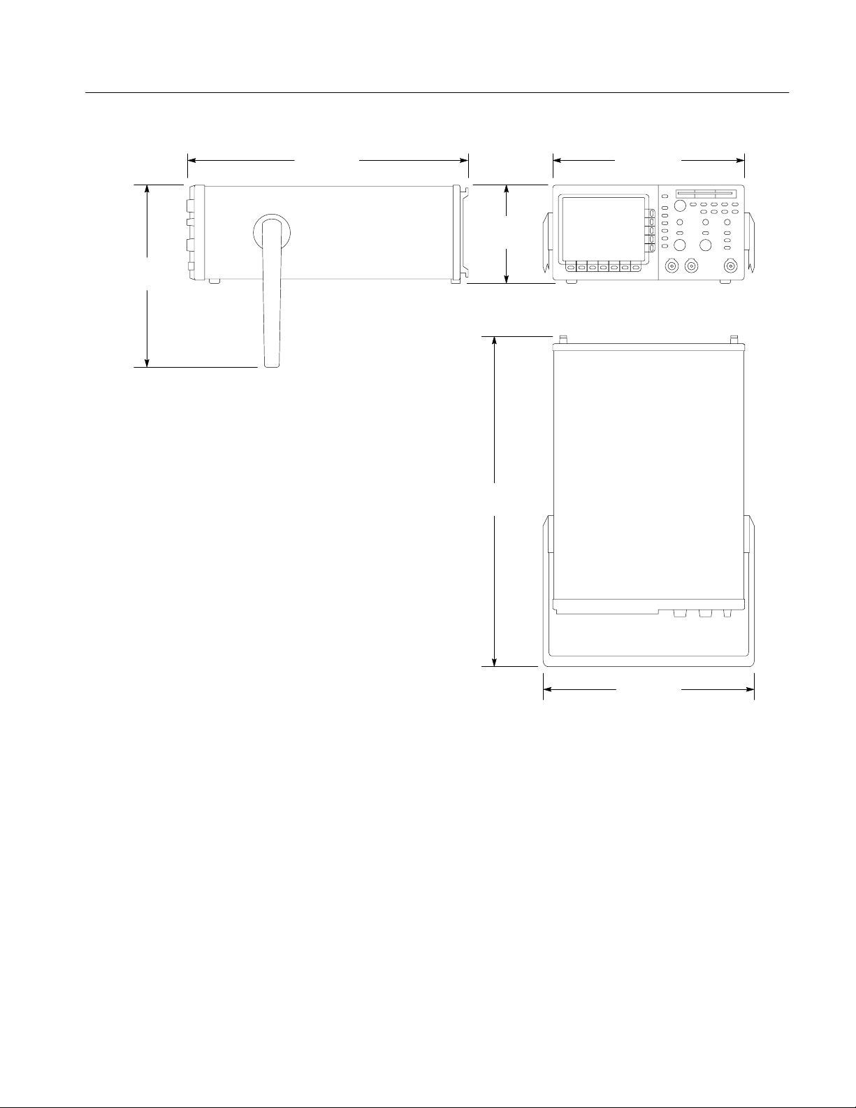
Overall Dimensions
Standard Instrument (Figure 1–1) Height: 191 mm (7.5 in) with feet and accessories pouch installed
165 mm (6.5 in) without the accessories pouch installed
Width: 362 mm (14.25 in) with handle
Depth: 471 mm (18.55 in) stand-alone instrument
490 mm (19.28 in) with front cover installed
564 mm (22.2 in) with handle extended
Rackmount Instrument Height: 178 mm (7 in)
Width: 483 mm (19 in)
Depth: 472 mm (18.6 in) without handles; 517 mm (20.35 in) including handles
1–10
TDS 340A, TDS 360 & TDS 380 Service Manual
Page 30
Specifications
308.1 mm
(12.13 in.)
471 mm
(18.55 in.)
327.2 mm
(12.88 in.)
165 mm
(6.5 in.)
569 mm
(22.4 in.)
Figure 1–1: TDS 340A, TDS 360, & TDS 380 dimensions
TDS 340A, TDS 360 & TDS 380 Service Manual
381 mm
(15 in.)
1–11
Page 31

Specifications
T able 1–17: Certifications and compliances
EC Declaration of Conformity Meets intent of Directive 89/336/EEC for Electromagnetic Compatibility and Low Voltage Directive
73/23/EEC for Product Safety. Compliance was demonstrated to the following specifications as
listed in the Official Journal of the European Communities:
EMC Directive 89/336/EEC:
EN 55011 Class B Radiated and Conducted Emissions
1
EN 50081-1 Emissions:
EN 60555-2 AC Power Line Harmonic Emissions
EN 50082-1 Immunity:
IEC 801-2 Electrostatic Discharge Immunity
IEC 801-3 RF Electromagnetic Field Immunity
2
IEC 801-4 Electrical Fast Transient/Burst Immunity
IEC 801-5 Power Line Surge Immunity
Low Voltage Directive 73/23/EEC:
EN 61010-1 Safety requirements for electrical equipment for measurement,
control, and laboratory use
1
To maintain emission requirements when connecting to the I/O interface of this oscilloscope,
use only a high-quality, double-shielded (braid and foil) cable. The cable shield must have
low-impedance connections to both connector housings. The VGA cable must also have a
ferrite core at both ends. Acceptable cables are listed in Table 7–6 on page 7–4.
2
Performance criteria: ≤±0.3 division waveform displacement, or ≤0.6 division increase in p-p
noise from 27 MHz to 500 MHz. Test conditions: both channel inputs terminated with
grounding caps, both channels set to 10 mV/div, both channels set to DC Coupling, trigger
source set to CH 1, acquisition mode set to Sample, and time base set to 250 s/div .
Certifications Underwriters Laboratories listing to Standard UL3111–1 for Electrical Measuring and Test
Equipment.
Canadian Standards Association certified to Standard CAN/CSA-C22.2 No. 1010.1–92.
3
4
3 4
3
These standards are North American interpretations of IEC 1010.
Conditions for certification: operating temperature –10_ C to +55_ C, maximum operating
altitude 2000 m, Safety Class I (IEC 1010-1 Annex H), Overvoltage Catagory II (IEC 1010-1
Annex J), Pollution Degree 2 (IEC 1010-1).
FCC Compliance Emissions comply with FCC Code of Federal Regulations 47, Part 15, Subpart B, Class A Limits
CSA Certified Power Cords CSA Certification includes the products and power cords appropriate for use in the North America
power network. All other power cords supplied are approved for the country of use.
Overvoltage Category Category: Examples of Products in this Category:
CA T III Distribution-level mains, fixed installation
CA T II
CA T I
Local-level mains, appliances, portable equipment
Signal levels in special equipment or parts of equipment, telecommu-
nications, electronics
Pollution Degree 2
Do not operate in environments where conductive pollutants may be present.
1–12
TDS 340A, TDS 360 & TDS 380 Service Manual
Page 32

Page 33

Operating Information
This section identifies and describes each control and connector on the TDS 300
Series oscilloscope. This chapter also describes how to use the oscilloscope
menu system. Refer to the TDS 340A, TDS 360 & TDS 380 User Manual for
more information on setting up and taking measurements with the oscilloscope.
Display and Power Controls
The ON/STBY button toggles
instrument power.
The Side Menu buttons provide
access to side menu selections.
Refer to page 2–7 for more
information about the user interface
Side Menu.
The CLEAR MENU button clears
all menus from the screen.
The Main Menu buttons provide access to
main menu selections. Refer to page 2–7
for more information about the user interface
Main Menu.
TDS 340A, TDS 360 & TDS 380 Service Manual
2–1
Page 34

Operating Information
V ertical Controls
The Waveform Select buttons display
and select waveforms (CH1, CH2, MATH,
REF1, and REF2). A light next to a button
illuminates when that waveform is
selected.
The Vertical POSITION knob controls
the vertical position of the selected
waveform.
The VERTICAL MENU button calls up
the vertical operations menu.
Connector to chassis ground.
Horizontal Controls
The Horizontal POSITION knob controls
the horizontal position of all waveforms.
The HORIZONTAL MENU button calls up
the horizontal operations menu.
The SCALE knob controls the horizontal
scale of the active waveforms.
Probe compensation output.
The SCALE knob controls the vertical
scale of the selected waveform.
The WAVEFORM OFF button turns
off the selected waveform.
2–2
TDS 340A, TDS 360 & TDS 380 Service Manual
Page 35

T rigger Controls
The SET LEVEL TO 50% button sets the
trigger level at the midpoint between the
peaks of the trigger signal.
The FORCE TRIGGER button forces the
oscilloscope to start acquiring a waveform
regardless of whether a trigger event
occurs. This button has no effect if the
acquisition system is stopped.
The Trigger LEVEL knob controls the
trigger.
The TRIGGER MENU button calls up
the trigger menu.
The trigger status lights indicate the
status of the triggering system. The
TRIG’D light illuminates when the
instrument recognizes a valid trigger.
The READY light illuminates when the
instrument can accept a valid trigger
and is waiting for that event to occur.
Operating Information
Inputs
The channel BNC inputs (CH1 and
CH2) accept electrical signals for
display.
The EXT TRIG input accepts external
trigger signals.
TDS 340A, TDS 360 & TDS 380 Service Manual
2–3
Page 36

Operating Information
Miscellaneous Controls
The MEASURE button calls up the
automated measurements menu.
The UTILITY button calls up the
utility menu.
The AUTOSET button automatically
sets up the instrument to produce a
usable display of the input signals.
The General Purpose Knob controls many
side-menu functions, including the cursors.
The SELECT button switches control from
cursor to cursor.
The floppy disk drive provides
mass storage for waveforms,
setups, and hard copies.
The HARDCOPY button starts
print operations.
(Requires Opt 14 installed)
The ACQUIRE button calls up the
The RUN/STOP button starts
and stops acquisition.
acquisition menu.
2–4
The SAVE/RECALL button calls up the
save/recall menu.
The CURSOR button calls up the
cursor menu.
The DISPLAY button calls up the
display menu.
TDS 340A, TDS 360 & TDS 380 Service Manual
Page 37

Display Map
Operating Information
Trigger position (T).
The Status Readouts show
trigger status and acquisition
status (mode and sampling rate
or number of acquisitions).
Trigger level indicator
Trigger point indicator
Channel ground
indicator
Indicates position
of vertical bar
cursors in the
waveform record.
Shows what part of the waveform record is displayed.
The waveform
record icon.
The value entered with the
general purpose knob.
When the general purpose
knob is first assigned, the
knob icon appears here.
Cursor measurement
readouts.
The side menu offers a
choice of specific
actions.
The Channel readout
shows the vertical scale of
all active channels.
The main menu offers a
choice of major actions.
TDS 340A, TDS 360 & TDS 380 Service Manual
The Time base readout shows the
time base setting. M indicates
(M)ain time base, D indicates
(D)elayed time base.
The Trigger readout shows
the trigger source and level
and whether the oscilloscope
is triggered on the rising or
falling edge of the waveform.
When in video-trigger mode,
the readout displays source
and trigger feature (Field 1,
Field 2, or Lines).
2–5
Page 38

Operating Information
Rear-Panel Connectors
The Option 14 Panel (Option 14 instruments only)
allows access to three communications interfaces:
a Centronics parallel port, an RS-232 interface,
and a GPIB interface. It also includes a VGA
video-compatible output port and a power
connector for the optional TDS4F5P printer
upgrade kit.
You can use the Centronics, RS-232, and GPIB
interfaces to transmit hardcopy data.
You can use the GPIB and RS-232 interfaces to
operate and program the oscilloscope from a GPIB
or RS-232 controller; see the TDS 340A, TDS 360
& TDS 380 Programmer Manual for more
information.
The power connector accepts line voltage
to power the instrument. Refer to page 7–2
for a list of power cord and connector
options.
The fuse drawer holds the line fuse. Refer to
page 6–8 for fuse replacement procedures.
2–6
TDS 340A, TDS 360 & TDS 380 Service Manual
Page 39

Using the Menu System
Operating Information
TDS 300 Series oscilloscopes use an intuitive user interface. This interface
reduces front-panel clutter while allowing easy access to specialized functions
through the menu structure.
The following procedure describes how to navigate in the menu structure. If you
are unfamiliar with this menu system, you may want to run through the
procedure several times to learn how you can access functions and subfunctions.
Figure 2–2 provides a graphic overview of using the menu system.
TDS 340A, TDS 360 & TDS 380 Service Manual
2–7
Page 40

Operating Information
1. Push a front-panel button to call up a menu of functions. This first menu is
the main menu. Sometimes the main menu will be a side menu (step 3), but
most main menus are bottom menus.
2. Push a main menu button to select a function. One of three things happens:
If the function has no subfunctions, it becomes active. If it is a variable
function, you can now use the General Purpose Knob to adjust it
(step 4).
If the function has subfunctions, they appear on the side menu (step 3).
The leftmost main menu button sometimes activates a pop-up menu (as
shown in Figure 2–1). You can cycle through the pop-up menu options
by repeatedly pressing the button. Each selection calls up different main
and side menus.
2–8
Figure 2–1: A pop-up menu
3. Push a side-menu button to select a subfunction.
4. Use the General Purpose knob to change variable-function or subfunction
settings.
5. Press the CLEAR MENU button to remove a menu from the screen.
TDS 340A, TDS 360 & TDS 380 Service Manual
Page 41

Operating Information
1
Press any of the front-panel menu buttons. Select an item from the main menu
34
Select an item from the side menu, if displayed. Adjust menu item values with general purpose knob.
2
or use leftmost button to pop up selections.
Figure 2–2: Using menus
TDS 340A, TDS 360 & TDS 380 Service Manual
2–9
Page 42

Operating Information
2–10
TDS 340A, TDS 360 & TDS 380 Service Manual
Page 43

Page 44

Theory of Operation
This section describes the electrical operation of the TDS 340A, TDS 360, and
TDS 380 to the module level.
Logic Conventions
This manual refers to digital logic circuits with standard logic symbols and
terms. Unless otherwise stated, all logic functions are described using the
positive logic convention: the more positive of the two logic levels is the high
(1) state and the more negative level is the low (0) state. Signal states may also
be described as “true” meaning their active state or “false” meaning their
non-active state. The specific voltages that constitute a high or low state vary
among the electronic devices.
Active-low signals are indicated by a tilde (~) prefixed to the signal name
(~RESET). Signal names are considered to be either active-high, active-low, or
to have both active-high and active-low states.
Module Overview
Input Signal Path
This overview describes the basic operation of each functional circuit block as
shown in Figures NO TAG through 3–2.
A signal enters the oscilloscope through a probe connected to a BNC on the A11
(TDS 340A), A12 (TDS 360), or A13 (TDS 380) Main Board.
Attenuators. Circuitry in the attenuator selects the input coupling and attenuation
factor. The processor system controls the attenuators with a serial interface.
Probe Coding Interface. The probe coding interface signals pass through the Main
Board to the A6 Front Panel, which senses them.
Acquisition System. The acquisition system amplifies the input signals, samples
them, converts them to digital signals, and controls the acquisition process under
direction of the processor system. The acquisition system includes the trigger,
acquisition timing, and acquisition mode generation and control circuitry.
TDS 340A, TDS 360 & TDS 380 Service Manual
3–1
Page 45

Theory of Operation
Bezel Button Flex
A9
10 Pins
P1
A6
Front Panel
J40
10 Pins
J35
4 Pins
J84
5 Pins
Cal Sig
Not Used
LV Power
A20
Supply
A11 (TDS 340A)
A12 (TDS 360)
A13 (TDS 380)
2 Pins
2 Pins
13 Pins
Main
J2
J3
J1
13
P2
P3
P1
2
2
Fan
J702
13 Pins
J702
8 Pins
J602
50 Pins
16 Pins
J30
TRIG
CH1
CH2
EXT
P30 P603
16
J53
J52
J51
J603
16 Pins
J605
J606
J607
Figure 3–1: TDS 340A, TDS 360, & TDS 380 block diagram
8
A5
JR3
50 Pins
Floppy interface
board
26 Pins
Monitor
A26
J901
10 Pins
Floppy disk drive
J1
26
J1
26 Pins
3–2
TDS 340A, TDS 360 & TDS 380 Service Manual
Page 46

Theory of Operation
A9
Bezel Button Flex
A6
Front Panel
10 Pins
10 Pins
4 Pins
5 Pins
16 Pins
P1
J40
J35
J84
J30
Cal Sig
Not Used
P30 P603
CH1
CH2
16
J53
J52
LV Power
A20
Supply
A11 (TDS340A)
A12 (TDS 360)
A13 (TDS 380)
J603
16 Pins
J605
J606
2 Pins
2 Pins
2 Pins
13 Pins
Main
J702
13 Pins
J703
6 Pins
J701
8 Pins
50 Pins
J601
J2
J4
J3
J1
13
P703
8
A5
JR3
50 Pins
P2
2
P4
P3
P1
Floppy interface
board
2
2
26 Pins
Fan
Option 14
A3
Printer Power
J1
2 Pins
A26
J901
10 Pins
26
J4
6 Pins
Monitor
Floppy disk drive
J1
26 Pins
6
2 Pins
9 Pins
J2
PWR
J3
VGA
J51
EXT
TRIG
J607
50 PinsJ2
P601
50
Figure 3–2: TDS 340A, TDS 360, and TDS 380 with Option 14 block diagram
TDS 340A, TDS 360 & TDS 380 Service Manual
A2
Option 14
I/O Interfaces
J1
50 Pins
50 Terminations
9 Pins
25 Pins
25 Pins
J2
RS232
J4
GPIB
J3
CENTRONICS
3–3
Page 47

Theory of Operation
Processor System. The processor system contains a 68331 microprocessor that
controls the entire instrument. The processor passes waveforms and text on to the
display system. The Main Board contains both the processor and display
systems, in addition to the firmware ROMs.
Display System. A display controller IC processes text and waveforms. The
display system sends the text and waveform information to the monitor assembly
as a video signal. The display system also generates and sends vertical (VSYNC)
and horizontal (HSYNC) sync signals to the monitor assembly.
Monitor
Front Panel
Floppy Disk Drive
All information (waveforms, text, graticules, and pictographs) is displayed by
the A26 Monitor. It generates the high voltages necessary to drive the display
tube. It also contains the video amplifier, horizontal oscillator, and the vertical
and horizontal yoke driver circuitry.
The processor system sends instructions to and receives information from the
Front Panel Processor on the Front Panel Board. The Front Panel Processor reads
the front-panel switches and ports, and reports any change in their settings to the
processor system. The Front Panel Processor also turns front panel LEDs on and
off.
The Front Panel Processor reads the front-panel menu switches and sends any
changes in menu selections to the processor system. The ON/STBY button is not
read by the Front Panel Processor but passes through the Front Panel Board and
the Main Board to the A20 Low Voltage Power Supply.
The front panel also generates the probe compensation signal.
The floppy disk drive system consists of the A5 floppy interface board that
connects to the main board. A 26-pin cable connects the floppy disk drive to the
floppy interface board, supplying both power and data to the drive.
3–4
Option 14
The drive is 2 Mbyte double-side, high-density unit that uses 3.5 inch IBM-format disks.
The A2 Option 14 board has GPIB, RS-232, and Centronics interfaces for
external control and hardcopy operations. Also included is the A3 board with a
VGA video output port and a power connector for the Option 3P printer.
TDS 340A, TDS 360 & TDS 380 Service Manual
Page 48

Theory of Operation
Low Voltage Power Supply
Fan
The A20 Low Voltage Power Supply is a switching power converter. It supplies
power to all the circuitry in the oscilloscope.
The Low Voltage Power Supply does not have a main power switch. The
ON/STBY switch, located on the front panel, controls all the power to the
oscilloscope except the standby circuits in the Low Voltage Power Supply.
The fan provides forced air cooling for the oscilloscope. It connects to a 12 V
connector on the Low Voltage Power Supply.
TDS 340A, TDS 360 & TDS 380 Service Manual
3–5
Page 49

Theory of Operation
3–6
TDS 340A, TDS 360 & TDS 380 Service Manual
Page 50

Page 51

Performance Verification
The procedures in this section verify that the TDS 340A, TDS 360, and TDS 380
oscilloscopes meet warranted specifications. There are three performance tests
that you can do.
To rapidly confirm that this oscilloscope functions, do the Self Test
procedures that begin on page 4–5.
Advantages: This procedure is quick to do, requires no external equipment
or signal sources, and performs extensive functional and accuracy testing to
provide high confidence that the oscilloscope performs properly. You can use
it as a quick check before making a series of important measurements.
To further check functionality, do the Functional Test procedures that begin
on page 4–7.
Advantages: These procedures require minimal additional time to perform,
require no additional equipment other than a standard-accessory probe, and
more completely test the internal hardware of this oscilloscope. You can use
them to quickly determine if the oscilloscope is suitable for putting into
service, such as when it is first received.
Conventions
If you need a more extensive confirmation of performance, do the
Performance Tests that begin on page 4–11, after doing the functional and
self tests.
Advantages: These procedures check warranted specifications. They require
more time and suitable test equipment. (See Test Equipment on page 4–3.)
Throughout these procedures the following conventions apply:
Each test procedure uses the following general format:
Title of test
Equipment required
Time required
Prerequisites
Procedure steps
TDS 340A, TDS 360 & TDS 380 Service Manual
4–1
Page 52

Performance Verification
Refer to Figure 4–1: “Main menu” refers to the menu that labels the seven
menu buttons under the display. “Side menu” refers to the menu that labels
the five buttons to the right of the display. “Pop-up menu” refers to a menu
that pops up when a main menu button is pressed.
Where instructed to use a front-panel button or knob, select from a main or
side menu, or verify a readout or status message, the name of the button or
knob appears in boldface type.
Instructions for menu selection follow this format: FRONT PANEL
BUTTON ! Pop-Up (if necessary) ! Main Menu Button ! Side Menu
Button. For example, “Push TRIGGER MENU ! Type: Video ! Trigger On ! Lines.”
STOP. This symbol denotes information you must read to do the procedure
properly.
Pop-Up Menu
Side Menu
Main Menu
Figure 4–1: Menu locations
4–2
TDS 340A, TDS 360 & TDS 380 Service Manual
Page 53

Test Equipment
T able 4–1: Test equipment
Item number
and description
Performance Verification
The performance test procedures require external, traceable signal sources to
check instrument performance. If your test equipment does not meet the
minimum requirements listed in Table 4–1, your test results will be invalid.
Minimum requirements Example Purpose
1. Termination 50 W
(two required)
2. Cable, Precision Coaxial
(two required)
3. Connector ,
Dual-Banana
4. Connector ,
BNC “T”
5. Coupler,
Dual-Input
6. Generator , DC Calibration Variable amplitude to ±110 V;
7. Generator ,
Leveled Sine Wave,
Medium-Frequency
8. Generator ,
Leveled Sine Wave,
High-Frequency
9. Generator , Time Mark Variable marker frequency from
10. Probe, 10X,
included with this
instrument
1
The high frequency leveled sine wave generator is only required to verify the TDS 380, not the TDS 340A or TDS 360. If
you use the example equipment, refer to
obtaining a leveled output from an unleveled sine wave generator
Sine Wave Generator in place of the example equipment.
1
Impedance 50 W; connectors:
female BNC input, male BNC
output
50 W, 91 cm (36 in), male to
male BNC connectors
Female-BNC to dual-banana Tektronix part number
Male-BNC to dual-female-BNC Tektronix part number
Female-BNC to dual-male-BNC Tektronix part number
accuracy to 0.1%
50 kHz to 250 MHz; variable
amplitude from 5mV to 4 V
into 50 W
50 kHz to 400 MHz; variable
amplitude from 5mV to 4 V
into 50 W
10 ms to 10 ns; accuracy within
2 ppm
A P6109B (TDS 340A), P6111B
(TDS 360), or P6114B
(TDS 380) probe
Tektronix part number
01 1-0049-01
Tektronix part number
012-0482-00
103-0090-00
103-0030-00
067-0525-02
Wavetek 9100 Calibration
System with Option 250 and
Option 100
Wavetek 9100 Calibration
System with Option 250 and
p-p
Option 100
Rohde & Schwarz SMY with
URV 35 Power Meter and
p-p
NRV-Z8 Power Sensor
Wavetek 9100 Calibration
System with Option 250 and
Option 100
T ektronix number
P6109B (TDS 340A), P6111B
(TDS 360), or P6114B
(TDS 380)
Sine Wave Generator Leveling Procedure on page 4–20 for information on
. If available, you can use a Tektronix SG504 Leveled
Checking delay between
channels
Signal interconnection
Several accuracy tests
Checking trigger sensitivity
Checking delay between
channels
Checking DC offset, gain, and
measurement accuracy
Checking bandwidth and trigger
sensitivity
Checking bandwidth and trigger
sensitivity
Checking sample rate and
delay-time accuracy
Signal interconnection
TDS 340A, TDS 360 & TDS 380 Service Manual
4–3
Page 54

Performance Verification
Test Record
Photocopy this page and use it to record the performance test results for your
instrument.
TDS 340A, TDS 360, and TDS 380 test record
Instrument Serial Number: Certificate Number:
Temperature: RH %:
Date of Calibration: Technician:
Performance test Minimum Incoming Outgoing Maximum
DC Voltage Measurement Accuracy
CH1 VOLTS/DIV 1 V
200 mV
1
50 mV
2
50 mV
D at 50 mV
10 mV
5 mV
CH2 VOLTS/DIV 1 V
200 mV
1
50 mV
2
50 mV
D at 50 mV
10 mV
5 mV
Analog bandwidth
CH1 42.5 mV __________ __________ N/A
CH2 42.5 mV __________ __________ N/A
Long term sample rate and delay time accuracy
Edge trigger sensitivity, DC coupled
+97.1 V
+8.28 V
–581 mV
–881 mV
+286 mV
+54.6 mV
–982 mV
+97.1 V
+8.28 V
–581 mV
–881 mV
+286 mV
+54.6 mV
–982 mV
–2.0 Div __________ __________ +2.0 Div
__________
__________
__________
__________
__________
__________
__________
__________
__________
__________
__________
__________
__________
__________
__________
__________
__________
__________
__________
__________
__________
__________
__________
__________
__________
__________
__________
__________
+98.9 V
+8.52 V
–619 mV
–919 mV
+314 mV
+65.4 mV
–998 mV
+98.9 V
+8.52 V
–619 mV
–919 mV
+314 mV
+65.4 mV
–998 mV
Main Trigger
Main Trigger – Falling
1
Generator set at –0.6 V.
2
Generator set at –0.9 V.
4–4
stable trigger
stable trigger
__________
__________
__________
__________
N/A
N/A
TDS 340A, TDS 360 & TDS 380 Service Manual
Page 55

Self Test
This procedure uses internal routines to verify that the oscilloscope functions and
passes its internal self tests and signal-path compensations. It also confirms that
the oscilloscope was adjusted properly at the time it was last adjusted. No test
equipment or hookups are required.
Equipment Required: None.
Time Required: Approximately 5 minutes.
Prerequisites: Power up the oscilloscope and allow a 20 minute warm up before
doing this procedure.
Procedure:
1. Press the front-panel button UTILITY.
2. Press the main-menu button System to select Diag.
3. Press the main-menu button Execute and then press the side-menu button
OK Confirm Run Test. The internal diagnostics verify proper oscilloscope
function. This verification takes about 30 seconds. While it progresses, a
variety of test patterns flash on screen. When finished, status messages
appear on the screen.
4. Check that the screen reports no failures. If it reports a failure, the oscilloscope has failed the self test. Contact your Tektronix representative for
assistance.
5. Press CLEAR MENU.
6. Press UTILITY and then press the main-menu button System to select Cal.
7. Check that the word Pass appears in the main menu under the Voltage
Reference, Timing, and Ext Trig menu labels. (See Figure 4–2.) If any of the
labels read Fail, the oscilloscope has failed the self test. Contact your
Tektronix representative for assistance.
TDS 340A, TDS 360 & TDS 380 Service Manual
4–5
Page 56

Self Test
First, display the Cal menu.
adjustment sections.
Third, run a signal path
compensation and verify
Second, verify Pass
status for the
status is Pass.
Figure 4–2: Verifying adjustments and signal path compensation
8. Press Signal Path and then press the side menu button OK Compensate
Signal Paths. When compensation completes, the status message updates to
Pass or Fail in the main menu
9. Check that the word Pass appears under Signal Path in the main menu. (See
Figure 4–2.) If Pass does not appear, the oscilloscope has failed the
performance verification; return it to Tektronix for servicing.
4–6
TDS 340A, TDS 360 & TDS 380 Service Manual
Page 57

Functional Test
This procedure confirms that the oscilloscope functions properly.
NOTE. This procedure verifies functions; that is, it verifies that oscilloscope
features operate. It does not verify that they operate within limits. Therefore,
when the instructions that follow call for you to verify that a signal appears
on-screen “that is about five divisions in amplitude” or “has a period of about
six horizontal divisions,” do NOT interpret the quantities given as limits.
Operation within limits is checked in the performance tests, which begin on
page 4–11.
DO NOT make changes to the front-panel settings that are not called out in the
procedure. If you make changes to these settings other than those called out in
the procedure, you may obtain invalid results. In this case, just redo the
procedure from step 1.
Equipment Required: One P6109B (TDS 340A), P6111B (TDS 360), or
P6114B (TDS 380) probe.
Time Required: Approximately 5 minutes.
Prerequisites: None.
Procedure:
1. Install the probe on CH 1. Connect the probe tip to PROBE COMP on the
front panel; leave the probe ground unconnected. (See Figure 4–3.)
Digitizing oscilloscope
Figure 4–3: Hookup for functional test
2. Press the front-panel button SAVE/RECALL, the main-menu button Recall
Factory Setup, and then the side-menu button OK Confirm Factory Init.
TDS 340A, TDS 360 & TDS 380 Service Manual
4–7
Page 58

Functional Test
3. Press AUTOSET.
4. Set the VOLTS/DIV to 1 V. Use the vertical POSITION knob to center the
waveform vertically on screen.
5. Set the SEC/DIV to 250 ms. Check that a square wave probe-compensation
signal of about five divisions in amplitude is on screen.
6. Check that one period of the square wave probe-compensation signal is
about four horizontal divisions on screen.
7. Check that the horizontal POSITION knob positions the signal left and right
on screen when rotated.
8. Press the front-panel button TRIGGER MENU, the main-menu button
Mode, and then the side-menu button Normal.
9. Check that the trigger-level readout for the main trigger system changes with
the trigger LEVEL knob.
10. Check that the trigger-level knob can trigger and untrigger the square-wave
signal as you rotate it. (Leave the signal untriggered.)
11. Check that pressing SET LEVEL TO 50% triggers the signal that you just
left untriggered.
12. Press the front-panel button ACQUIRE, the main-menu button Mode, and
then the side-menu button Sample.
13. Check that the oscilloscope displays an actively acquiring waveform. (Note
that there is noise present on the peaks of the square wave.)
14. Press the side-menu button Peak Detect. Check that the oscilloscope
displays an actively acquiring waveform with the noise “peak detected.”
15. Press the side-menu button Envelope. Check that the oscilloscope displays
an actively acquiring waveform with the noise displayed.
16. Press the side-menu button Average. Check that the oscilloscope displays an
actively acquiring waveform with the noise reduced.
17. Press WAVEFORM OFF to remove Channel 1 from the display.
18. Press CH 2 and move the probe to the CH 2 input.
19. Repeat steps 3 through 16 for Channel 2.
20. Disconnect the probe from the channel input and the PROBE COMP
terminal. You are done running the oscilloscope functional test.
4–8
TDS 340A, TDS 360 & TDS 380 Service Manual
Page 59

File System Functional Test
Equipment Required: One 720K or 1.44Mbyte, 3.5 inch DOS-compatible disk
(formatted).
Time Required: Approximately 5 minutes.
Prerequisites: None.
Procedure:
1. Install the probe on CH 1. Connect the probe tip to PROBE COMP on the
front panel; leave the probe ground unconnected. (See Figure 4–4.)
Functional Test
Digitizing oscilloscope
Figure 4–4: Hookup for file system functional test
2. Insert the disk in the disk drive.
3. Push the SAVE/RECALL front-panel button.
4. Push the Recall Factory Setup main-menu button.
5. Push the OK Confirm Factory Init side-menu button.
6. Push the trigger SET LEVEL TO 50% front-panel button.
7. Set the horizontal SCALE to 250 ms.
8. Push the Save Current Setup main-menu button.
9. Push the To File side-menu button.
10. Turn the general purpose knob to select the file to which to save the current
settings. Select . This saves the settings to a file starting with
, then containing five digits, and a .SET extension. For example, if you
are using a blank disk, the file name will be .
11. Push the Save To Selected File side-menu button. The oscilloscope writes
the current settings out to the file.
TDS 340A, TDS 360 & TDS 380 Service Manual
4–9
Page 60

Functional Test
12. Push the SAVE/RECALL front-panel button.
13. Push the Recall Factory Setup main-menu button.
14. Push the OK Confirm Factory Init side-menu button. This restores the
oscilloscope settings to those before you saved the settings.
15. Push the Recall Saved Setup main-menu button.
16. Push the From File side-menu button.
17. Turn the general purpose knob to select the file to which you saved the
settings (step 10). If you used a blank floppy disk, this file is .
18. Push the Recall From Selected File side-menu button. The oscilloscope
reads the current settings from the selected file and resets its settings. The
displayed signal should show a horizontal setting of 250 ms and the trigger at
50%.
19. Disconnect the probe from the channel input and the PROBE COMP
terminal. You are done running the file system functional test.
4–10
TDS 340A, TDS 360 & TDS 380 Service Manual
Page 61

Performance Tests
These procedures confirm that the oscilloscope functions within warranted
limits.The procedures are in three groupings: Signal Acquisition System Checks,
Time Base System Checks, and Trigger System Checks. They check all the
characteristics that appear in boldface type under Warranted Characteristics on
page 1–1.
Prerequisites
The tests in this subsection comprise an extensive, valid confirmation of
performance and functionality when the following requirements are met:
H The cabinet must be installed.
H You must have performed and passed the procedures under Self Test, on
H The oscilloscope must have been operating for a warm-up period of at least
page 4–5, and those under Functional Test, on page 4–7.
20 minutes, and must be operating at an ambient temperature between
–10_ C and +55_ C.
Signal Acquisition System Checks
These procedures check signal acquisition system characteristics that are listed as
checked under Warranted Characteristics in the Specifications section.
Check DC Voltage
Measurement Accuracy
WARNING. Performance of this procedure requires input voltages up to 98 VDC.
Contact with live circuits could cause injury or death. Be sure to set the DC
calibration generator to 0 volts before connecting, disconnecting, or moving the
test hookup during the performance of this procedure.
TDS 340A, TDS 360 & TDS 380 Service Manual
4–11
Page 62

Performance Tests
Equipment Required: One dual-banana connector (Item 3), one DC calibration
generator (Item 6), and one precision coaxial cable (Item 2).
Time Required: Approximately 35 minutes.
Prerequisites: The oscilloscope must meet the prerequisites listed on page 4–11.
Procedure:
1. Set the output of a DC calibration generator to 0 volts.
2. Connect the output of a DC calibration generator through a dual-banana
connector followed by a 50 W precision coaxial cable to CH 1, as shown in
Figure 4–5.
Digitizing oscilloscope
DC calibrator
Output Sense
HI
LO
Dual banana to
BNC adapter
Coaxial cable
Figure 4–5: Hookup for DC voltage measurement accuracy check
3. Press SAVE/RECALL SETUP ! Recall Factory Setup ! OK Confirm
Factory Init.
4. Press ACQUIRE ! Mode ! Average 16.
5. Press MEASURE ! Select Measurement.
6. Press the side menu button more until the menu label Mean appears in the
side menu. Press the side menu button Mean.
7. Set the vertical SCALE to one of the settings listed in Table 4–2 that you
have not yet checked. (Start with the first setting listed.)
8. Press VER TICAL MENU ! Position.
9. Turn the General Purpose Knob to set the vertical position to the setting
listed in Table 4–2. The baseline level moves off screen.
4–12
10. Press the main menu button Offset.
TDS 340A, TDS 360 & TDS 380 Service Manual
Page 63

Performance Tests
11. Use the General Purpose Knob to set vertical offset to the setting listed in
Table 4–2 for the present vertical scale setting. The baseline level remains off
screen.
T able 4–2: DC accuracy
Vertical scale
setting
1V +5 +100 V +98 V +97.1 V to +98.9 V
200 mV +5 +10 V +8.4 V +8.28 V to +8.52 V
50 mV –5 –1 V –0.6 V –581 mV to –619 mV
50 mV –5 –1 V –0.9 V –881 mV to –919 mV
n at 50 mV
10 mV –5 0 V +60 mV +54.6 mV to +65.4 mV
5mV 0 –1 V –990 mV –982 mV to –998 mV
Position
setting (divs)
Offset setting
Generator
setting
Accuracy limits
+286 mV to +314 mV
12. Set the generator to the level and polarity indicated in Table 4–2 for the
vertical scale, position, and offset settings you have made. The DC test level
should appear on screen. (If it does not return, the DC accuracy check has
failed for the present vertical scale setting of the current channel.)
13. Check that the readout for the measurement Mean readout on screen is
within the limits listed for the present vertical scale and position/offset/generator settings.
14. Repeat steps 7 through 13 until you have checked all the vertical scale
settings listed in Table 4–2. Record the measurements for each of the 50 mV
settings.
15. Subtract the second 50 mV measurement from the first and compare the
result to the “D at 50 mV” limits in Table 4–2.
16. Press WAVEFORM OFF; then, press CH 2.
17. Set the generator output to 0 V.
18. Move the test hookup to the CH 2 input.
19. Repeat steps 5 through 15 for channel 2.
20. Set the generator output to 0 V.
21. Disconnect the cable at the CH 2 input connector.
TDS 340A, TDS 360 & TDS 380 Service Manual
4–13
Page 64

Performance Tests
DC Gain Accuracy
Offset Accuracy
Check Analog Bandwidth
DC gain accuracy is verified by successful completion of the self tests and the
DC voltage measurement accuracy (in the previous procedure).
Offset accuracy is verified by successful completion of the self tests and the DC
voltage measurement accuracy (in the previous procedure).
Equipment Required: One leveled sine wave generator (Item 7 or 8), one 50 W
precision cable (Item 2), and one 50 W termination (Item 1).
Time Required: Approximately 20 minutes.
Prerequisites: See page 4–11.
Procedure:
1. Connect, through a 50 W precision cable and a 50 W termination, the sine
wave output of a leveled sine wave generator to CH 1 (see Figure 4–6). Set
the output of the generator to a reference frequency of 50 kHz.
NOTE. If you are verifying a TDS 380, you need a leveled sine wave generator
with a 400 MHz output frequency. Refer to Sine Wave Generator Leveling
Procedure on page 4–20 for information on obtaining a leveled output from an
unleveled sine wave generator.
Leveled
sine wave
generator
Output
Digitizing oscilloscope
50 W termination
Figure 4–6: Hookup for analog bandwidth check
1. Press SAVE/RECALL SETUP ! Recall Factory Setup ! OK Confirm
Factory Init.
2. Set the horizontal SCALE to 10 ms/div.
3. Press TRIGGER MENU ! Coupling ! Noise Rej.
4. Press ACQUIRE ! Mode ! Average 16.
4–14
TDS 340A, TDS 360 & TDS 380 Service Manual
Page 65

Performance Tests
5. Press MEASURE ! High-Low Setup ! Min-Max.
6. Press the main menu button Select Measurement. Now press the side menu
button more until the menu label Pk-Pk appears in the side menu. Press the
side menu button Pk-Pk.
7. Set the vertical SCALE to 10 mV/div.
8. Set the generator output so the CHx Pk-Pk readout equals 60 mV.
9. Press SET LEVEL TO 50% as necessary to trigger the display.
10. Increase the frequency of the generator output to 100 MHz (TDS 340A),
200 MHz (TDS 360), or 400 MHz (TDS 380).
11. Set the horizontal SCALE to 5 ns/div (TDS 340A), 2.5 ns/div (TDS 360), or
2.5 ns/div (TDS 380).
12. Press SET LEVEL TO 50% as necessary to trigger the display.
13. Check that the Pk-Pk readout on screen (as shown in
Figure 4–7) is 42.5 mV.
First, increase the reference
frequency to the test frequency;
then decrease the horizontal
scale.
Second, read the results
from the readout of
measurement Pk-Pk.
Figure 4–7: Measuring analog bandwidth
TDS 340A, TDS 360 & TDS 380 Service Manual
4–15
Page 66

Performance Tests
14. When finished checking, set the horizontal SCALE back to the 10 ms/div
15. Press WAVEFORM OFF to remove Channel 1 from the display.
16. Press CH 2 and move the hookup to the CH 2 input.
17. Press TRIGGER MENU ! Source ! CH 2.
18. Repeat steps 6 through 13 for CH 2.
19. Disconnect the test hook up from the CH 2 input connector.
Time Base System Checks
This procedure checks those characteristics that relate to the Main and Delayed
time base system and are listed as checked under Warranted Characteristics in
the Specifications section.
setting, and set the generator output frequency back to 50 kHz.
Check Long-Term Sample
Rate and Delay Time
Accuracy
Equipment Required: One time-marker generator (Item 9), one precision
coaxial cable, (Item 2) and one 50 W termination (Item 1).
Time Required: Approximately 5 minutes.
Prerequisites: See page 4–11.
Procedure:
1. Connect, through a 50 W precision coaxial cable and a 50 W termination, the
time-mark output of a time-marker generator to CH 1, as shown in
Figure 4–8. Set the output of the generator for 10 ms markers.
Time mark
generator
Output
Digitizing oscilloscope
50 W termination
Figure 4–8: Hookup for sample rate check
4–16
TDS 340A, TDS 360 & TDS 380 Service Manual
Page 67

Performance Tests
2. Press SAVE/RECALL SETUP ! Recall Factory Setup ! OK Confirm
Factory Init.
3. Set the vertical SCALE to 500 mV/div.
4. Press SET LEVEL TO 50%; use the vertical POSITION knob to center
the test signal on screen.
5. Set the horizontal SCALE to 1 ms/div.
6. Press HORIZONTAL MENU ! Trigger Position ! Set to 10%.
7. Adjust the horizontal POSITION to move the trigger T to the right and on
to the screen. Continue to position the trigger T to align it to the center
vertical graticule line.
8. Press the main menu button Time Base; then press the side menu button
Delayed Only.
9. Set the horizontal SCALE of the D (delayed) time base to 1 ms/div. Then
use the General Purpose knob to set delay time to 10 ms.
Delta Time Measurement
Accuracy
10. Set the horizontal SCALE of the D (delayed) time base to 500 ns/div.
NOTE. When you change the SEC/DIV in step 10, the delay time readout
changes to 10.00001 or 9.99999. This is normal and has no effect on the
verification
11. Check that the rising edge of the marker crosses the center horizontal
graticule line at a point within ±2.0 divisions of the graticule center.
NOTE. One division of displacement from the center graticule corresponds to
a 50 ppm time base error.
12. Disconnect the test hookup.
Delta time measurement accuracy is verified by successful completion of the
previous procedure.
TDS 340A, TDS 360 & TDS 380 Service Manual
4–17
Page 68

Performance Tests
Trigger System Checks
These procedures check those characteristics that relate to the trigger system and
are listed as checked under Warranted Characteristics in the Specifications
section.
Check Edge Trigger
Sensitivity, DC Coupled
Equipment Required: One leveled sine wave generator (Item 7 or 8), two
precision 50 W coaxial cables (Item 2), one 50 W termination (Item 1), and one
BNC T connector (Item 4).
Time Required: Approximately 10 minutes.
Prerequisites: See page 4–11.
Procedure:
1. Press SAVE/RECALL SETUP ! Recall Factory Setup ! OK Confirm
Factory Init.
2. Set the vertical SCALE to 500 mV/div.
3. Set the horizontal SCALE to 10 ns/div.
4. Press TRIGGER MENU ! Mode ! Normal.
5. Press ACQUIRE ! Mode ! Average 16.
6. Connect one 50 W cable to the output of the sine wave generator. Attach a
BNC T connector to the other end of the cable. Connect a second 50 W cable
to the other side of the BNC T connector.
7. Connect the BNC T connector to CH 1; connect the cable to the EXT TRIG
input through a 50 W termination as shown in Figure 4–9.
4–18
Leveled
sine wave
generator
Output
Digitizing oscilloscope
Figure 4–9: Hookup for trigger sensitivity check
TDS 340A, TDS 360 & TDS 380 Service Manual
EXT TRIG
50 W termination
Page 69

Performance Tests
8. Set the generator frequency to 100 MHz (TDS 340A), 200 MHz (TDS 360),
or 400 MHz (TDS 380).
9. Press MEASURE ! High-Low Setup ! Min-Max.
10. Press the main menu button Select Measurement.
11. Press the side menu button -more- until Amplitude appears in the side
menu. Press the side menu button Amplitude.
12. Press SET LEVEL TO 50%.
13. Set the test signal amplitude for about one division on screen. Fine adjust the
generator output until the CH 1 Amplitude readout indicates the amplitude
is 500 mV. (Readout may fluctuate around 500 mV.)
14. Press TRIGGER MENU ! Slope.
15. Press SET LEVEL TO 50%. Check that a stable trigger is obtained for the
test waveform on both the positive and negative slopes (see Figure 4–10).
(Use the side menu to switch between trigger slopes; use the trigger LEVEL
knob to stabilize the trigger if required.)
First, set a signal with an
amplitude at the minimum trigger
sensitivity.
Second, check for a stable
trigger at both the positive and
negative slope settings.
Figure 4–10: Measuring trigger sensitivity
TDS 340A, TDS 360 & TDS 380 Service Manual
4–19
Page 70

Performance Tests
16. Press WAVEFORM OFF.
17. Press CH 2.
18. Press TRIGGER MENU ! Source ! Ch2.
19. Disconnect the hookup from CH 1 and connect it to CH 2.
20. Set the vertical SCALE to 500 mV/div.
21. Repeat steps 14 and 15 for Channel 2.
22. Press TRIGGER MENU ! Source ! EXT/10.
23. Press MEASURE ! Select Measrmnt ! Amplitude.
24. Increase the generator amplitude until the amplitude measurement reads
1.5 V if you are checking a TDS 340A or TDS 360. Increase the generator
amplitude until the amplitude measurement reads 4.0 V if you are checking a
TDS 380.
25. Repeat steps 14 and 15 for the external trigger.
26. Disconnect the test hookup.
Trigger Level Accuracy,
DC Coupled
Trigger level accuracy is verified by the successful completion of the Self Tests
and the DC voltage measurement accuracy procedure on page 4–11.
This completes the performance verification procedure.
Sine Wave Generator Leveling Procedure
Some procedures in this manual require a sine wave generator to produce the
necessary test signals. If you do not have a leveled sine wave generator, use the
following procedure to level the output amplitude of your sine wave generator
using a power meter.
Equipment Required: Sine wave generator, level meter and power sensor,
power splitter, and one precision coaxial cable.
Time Required: About 5 minutes.
Prerequisites:
See page 4–11.
4–20
Procedure:
1. Connect the equipment as shown in Figure 4–11.
2. Set the sine wave generator to a reference frequency of 50 kHz.
TDS 340A, TDS 360 & TDS 380 Service Manual
Page 71

Performance Tests
3. Adjust the sine wave generator amplitude to the required number of
divisions as measured by the oscilloscope.
4. Note the reading on the level meter.
5. Change the sine wave generator to the desired new frequency.
6. Input the correction factor for the new frequency into the level meter.
7. Adjust the sine wave generator amplitude until the level meter again reads
the value noted in step 4. The signal amplitude is now correctly set for the
new frequency.
Sine wave
generator
Output
Digitizing oscilloscope
Power splitter
Attenuators
(if necessary)
Power sensor
Figure 4–11: Hookup for sine wave generator leveling
Level
meter
Input
TDS 340A, TDS 360 & TDS 380 Service Manual
4–21
Page 72

Performance Tests
4–22
TDS 340A, TDS 360 & TDS 380 Service Manual
Page 73

Page 74

Adjustment Procedures
This section contains information you need to adjust the TDS 340A, TDS 360,
and TDS 380. There are only three types of adjustments you can perform on the
oscilloscope: the automated and semiautomated adjustments in the system
calibration menu, attenuator adjustments, and monitor adjustments.
You should perform the signal path compensation adjustment after servicing
your instrument or moving your instrument to a new operating environment
(±5_ C temperature change). The other adjustment procedures may be necessary
if the instrument fails one of the Performance Tests in the previous section.
You should allow the instrument a 20 minute warm-up period before performing
any adjustments.
Adjustment Interval. These adjustments should be done once a year.
Equipment Required
Table 5–1 lists the equipment you will need to do the adjustment procedures.
T able 5–1: Adjustment equipment
Item number
and description
1. Adjustment Tool 0.075 inch slot screwdriver Tektronix part number
2. Termination, 50 W Impedance 50 W; connectors:
3. Cable, Precision Coaxial 50 W, 36 in, male to male BNC
4. Generator ,
DC Calibration
5. Generator ,
Fast-rise Step
Minimum requirements Example Purpose
003-1433-01 (standard probe
adjustment tool)
Tektronix part number
female BNC input, male BNC
output
connectors
Variable amplitude to ±10 V;
accuracy to 0.05%
tr ≤ 10 ns;
amplitude ≤ 1 V
p-p
01 1-0049-01
Tektronix part number
012-0482-00
Wavetek 9100 Calibration
System with Option 250
Wavetek 9100 Calibration
System with Option 250
Monitor and attenuator adjustments
Timing calibration and attenuator adjustment
Attenuator adjustments and
system calibration
Voltage and external trigger
calibrations
Timing calibration and attenuator adjustment
TDS 340A, TDS 360 & TDS 380 Service Manual
5–1
Page 75

Adjustment Procedures
The System Calibration Menu
The oscilloscope has four onboard calibration routines. You can access these
routines through the system calibration menu. Use the following procedure.
NOTE. The Voltage, Timing, and External Trigger calibration routines are
disabled at the factory. To enable the calibration menus, refer to Enabling
Calibration Menus on page 6–31.
Equipment Required: One DC calibration generator (Item 4), one precision
coaxial cable (Item 3), one fast–rise step generator (Item 5), and one 50 W
termination (Item 2).
1. Press UTILITY.
2. Press the leftmost main menu button until the pop-up menu shows the Cal
selection. This calls up the system calibration menu, shown in Figure 5–1.
5–2
Figure 5–1: The system calibration menu
3. Remove all input signals from the front panel BNC connectors.
4. Press the main menu button Voltage Reference. Read the on-screen text
before continuing.
TDS 340A, TDS 360 & TDS 380 Service Manual
Page 76

Adjustment Procedures
5. Press the side menu button OK Calibrate Voltage Ref. Connect a DC
calibration generator (Item 4) to the CH 1 input through a 50 W coaxial
cable (Item 3) and follow the instructions on the screen.
6. Press UTILITY.
7. Press the main menu button Signal Path. Read the on-screen text before
continuing.
8. Press the side menu button OK Compensate Signal Paths.
9. Wait. The signal path compensation routine takes about four minutes to run.
10. Move the DC calibration generator (Item 4) from the CH 1 input to the
EXT TRIG input.
11. Press UTILITY.
12. Press the main menu button Ext Trig. Read the on-screen text before
continuing.
13. Press the side menu button OK Calibrate External Trig. Follow the
instructions on the screen.
14. Disconnect the DC calibration generator and connect the –1 V fast rise
output of a calibration generator to the CH 1 input through a 50 W coaxial
cable and a 50 W termination (Item 2).
15. Set the calibration generator to output a 1 ms, fast rise signal; set the pulse
amplitude to 50%.
16. Press SAVE/RECALL SETUP. Press the main menu button Recall Factory
Setup; then press the side menu button OK Confirm Factory Init.
17. Press AUTOSET. Then adjust the vertical POSITION control to center the
waveform on the screen so that the trigger arrow is at the center graticule, set
the VOLTS/DIV to 50 mV, and set the SEC/DIV to 250 ns. This should
result in a waveform similar to the one shown in Figure 5–2.
TDS 340A, TDS 360 & TDS 380 Service Manual
5–3
Page 77

Adjustment Procedures
Attenuator Adjustment
Figure 5–2: Timing compensation waveform
18. Press UTILITY.
19. Press the main menu button Timing. Read the on-screen text before
continuing.
20. Press the side menu button OK Compensate Timing. Follow the instruc-
tions on the screen.
Use this procedure to adjust the low-frequency compensation of the channel 1
and channel 2 attenuators. You should perform this procedure if your oscilloscope demonstrates gross rounding or overshoot of square-wave input signals or
if your instrument fails one of the Performance Tests in the previous section.
Equipment Required: One adjustment tool (Item 1), one precision coaxial cable
(Item 3), one fast–rise step generator (Item 5), and one 50 W termination (Item
2).
1. Remove the instrument cabinet as described in the removal procedure on
page 6–11.
5–4
2. Set the oscilloscope on its left side with its front facing toward you.
3. Power up the oscilloscope and press SAVE/RECALL SETUP.
TDS 340A, TDS 360 & TDS 380 Service Manual
Page 78

Adjustment Procedures
4. Press the main menu button Recall Factory Setup; then press the side menu
button OK Confirm Factory Init.
5. Press CLEAR MENU.
6. Connect the high output of a fast–rise step generator (Item 5) to the CH 1
BNC through a 50 W coaxial cable (Item 3) and a 50 W termination (Item 2).
(See Figure 5–3.)
7. Set the calibration generator to output a high amplitude, 1 kHz signal. Set
the pulse amplitude to 25%.
8. Set the oscilloscope VOLTS/DIV to 200 mV, the SEC/DIV to 10 ms, and
adjust the pulse amplitude for a five division display.
9. Press SET LEVEL TO 50%.
10. Use the vertical POSITION control to place the top of the waveform near
center screen.
11. Set the VOLTS/DIV to 100 mV.
Digitizing oscilloscope
12. Use an adjustment tool (Item 1) to adjust the CH 1 10X capacitor for the
flattest response. (See Figure 5–3.)
13. Remove the 50 W termination from the setup.
14. Set the VOLTS/DIV to 2 V.
View from bottom of instrument
50 W termination
Fast–rise step
generator
10X adjustment 100X adjustment
Output
Front of instrument
CH 2
CH 1
Figure 5–3: Attenuator adjustment setup and locations
TDS 340A, TDS 360 & TDS 380 Service Manual
5–5
Page 79

Adjustment Procedures
15. Press SET LEVEL TO 50%.
16. Adjust the pulse amplitude for a five-division display.
17. Set the VOLTS/DIV to 1 V.
18. Use an adjustment tool to adjust the CH 1 100X capacitor for the flattest
response.
19. Press WAVEFORM OFF, CH 2, and TRIGGER MENU, in that order.
20. Press the main menu button SOURCE; then press the side menu button
Ch2.
21. Move the coaxial cable to the CH 2 BNC input, reinstalling the 50 W
termination.
22. Repeat steps 7 through 18 for channel 2.
23. Reinstall the instrument cabinet.
Monitor Adjustments
There are no set performance requirements for the monitor. You may use this
procedure to change monitor parameters whenever the brightness, contrast,
horizontal position, or vertical position of the display is not to your liking.
Equipment Required: One adjustment tool (Item 1).
1. Remove the instrument cabinet as described in the removal procedure on
page 6–11.
2. Set the oscilloscope bottom-down with its front facing toward you.
3. Turn on the oscilloscope and allow a 20 minute warm-up period.
4. Press DISPLAY.
5. Press the main menu button Intensity. Use the side menu to set overall
intensity to 100%, Text/Grat to bright, and Waveform to bright.
6. Locate the brightness potentiometer (see Figure 5–4). Use an adjustment tool
(Item 1) to raise the brightness until the background of the screen turns
green.
5–6
TDS 340A, TDS 360 & TDS 380 Service Manual
Page 80

Left side of instrument
Adjustment Procedures
Vertical position
Horizontal position
Brightness
Contrast
Front of instrument
Figure 5–4: Monitor adjustments
7. Now lower the brightness just beyond the point where the background fades
to black.
8. Locate the contrast potentiometer. Adjust the contrast to your taste.
CAUTION. The higher the contrast, the higher the likelihood that prolonged use
will cause CRT burn-in.
9. Locate the vertical position potentiometer. Adjust the vertical position until
the display is vertically centered on the screen.
10. Locate the horizontal position potentiometer. Adjust the horizontal position
until the display is horizontally centered on the screen.
TDS 340A, TDS 360 & TDS 380 Service Manual
5–7
Page 81

Adjustment Procedures
5–8
TDS 340A, TDS 360 & TDS 380 Service Manual
Page 82

Page 83

Maintenance
Preventing ESD
This chapter describes how to inspect, clean, remove, and troubleshoot the
oscilloscope at the module level.
Preventive maintenance, when done regularly, may prevent oscilloscope
malfunction and enhance its reliability. Preventive maintenance consists of
visually inspecting and cleaning the oscilloscope and using general care when
operating it. How often to do maintenance depends on the severity of the
environment in which you use the oscilloscope. A proper time to perform
preventive maintenance is just before oscilloscope adjustment.
CAUTION. Static discharge can damage any semiconductor component in this
oscilloscope.
Precautions
When performing any service which requires internal access to the oscilloscope,
adhere to the following precautions to avoid damaging internal modules and their
components due to electrostatic discharge (ESD).
1. Minimize handling of static-sensitive modules.
2. Transport and store static-sensitive modules in their static protected
containers. Label any package that contains static-sensitive modules.
3. Discharge the static voltage from your body by wearing a grounded antistatic
wrist strap while handling these modules. Do service of static-sensitive
modules only at a static-free work station.
4. Do not remove the oscilloscope cabinet unless you have met precaution
number 3, above. Consider all internal modules static-sensitive.
5. Nothing capable of generating or holding a static charge should be allowed
on the work station surface.
6. Handle circuit boards by the edges when possible.
7. Do not slide the modules over any surface.
8. Avoid handling modules in areas that have a floor or work-surface covering
capable of generating a static charge.
9. Do not use high-velocity compressed air when cleaning dust from modules.
TDS 340A, TDS 360 & TDS 380 Service Manual
6–1
Page 84

Maintenance
General Care
The cabinet helps keep dust out of the oscilloscope and it is a major component
of its cooling system. It should normally be in place when operating the
oscilloscope. The optional oscilloscope front cover protects the front panel and
display from dust and damage. Install it when storing or transporting the
oscilloscope.
Inspection and Cleaning Procedures
Inspect and clean the oscilloscope as often as operating conditions require. The
collection of dirt on components inside can cause them to overheat and
breakdown. (Dirt acts as an insulating blanket, preventing efficient heat
dissipation.) Dirt also provides an electrical conduction path
oscilloscope failure, especially under high-humidity conditions.
CAUTION. Avoid the use of chemical cleaning agents that might damage the
plastics used in this oscilloscope. Use only deionized water when cleaning the
menu buttons or front-panel buttons. Use a 75% isopropyl alcohol solution as a
cleaner and rinse with deionized water. Before using any other type of cleaner,
consult your Tektronix Service Center or representative.
that could cause an
Inspection — Exterior
Avoid the use of high pressure compressed air when cleaning dust from the
interior of this instrument. (High pressure air can cause ESD.) Instead, use low
pressure compressed air (about 9 psi).
Using Table 6–1 as a guide, inspect the outside of the oscilloscope for damage,
wear, and missing parts. You should thoroughly check oscilloscopes that appear
to have been dropped or otherwise abused to verify correct operation and
performance. Immediately repair defects that could cause personal injury or lead
to further damage to the oscilloscope.
6–2
TDS 340A, TDS 360 & TDS 380 Service Manual
Page 85

T able 6–1: External inspection check list
Item Inspect for Repair action
Maintenance
Cabinet, front panel, and cover Cracks, scratches, deformations, damaged
hardware or gaskets
Front-panel knobs Missing, damaged, or loose knobs Repair or replace missing or defective knobs
Connectors Broken shells, cracked insulation, and
deformed contacts. Dirt in connectors
Carrying handle and cabinet feet Correct operation Replace defective module
Accessories Missing items or parts of items, bent pins,
broken or frayed cables, and damaged
connectors
Replace defective module
Replace defective modules. Clear or wash out
dirt
Replace damaged or missing items, frayed
cables, and defective modules
Cleaning Procedure —
Exterior
WARNING. To avoid injury or death, unplug the power cord from line voltage
before cleaning the oscilloscope. To avoid getting moisture inside the oscilloscope during external cleaning, use only enough liquid to dampen the cloth
or applicator.
1. Remove loose dust on the outside of the oscilloscope with a lint free cloth.
2. Remove remaining dirt with a lint free cloth dampened in a general purpose
detergent-and-water solution. Do not use abrasive cleaners.
3. Clean the monitor screen with a lint-free cloth dampened with either isopro-
pyl alcohol or, preferably, a gentle, general purpose detergent-and-water
solution.
Inspection — Interior
To access the inside of the oscilloscope for inspection and cleaning, refer to the
Removal and Replacement procedures in this section.
Inspect the internal portions of the oscilloscope for damage and wear, using
Table 6–2 as a guide. You should repair defects immediately.
If you replace any electrical module, perform the adjustment procedures,
beginning on page 5–1.
CAUTION. To prevent damage from electrical arcing, ensure that circuit boards
and components are dry before applying power to the oscilloscope.
TDS 340A, TDS 360 & TDS 380 Service Manual
6–3
Page 86

Maintenance
T able 6–2: Internal inspection check list
Item Inspect for Repair action
Circuit boards Loose, broken, or corroded solder connec-
tions. Burned circuit boards. Burned, broken,
or cracked circuit-run plating
Resistors Burned, cracked, broken, or blistered condition Remove the module with the faulty resistor
Solder connections Cold solder or rosin joints Resolder joint and clean with isopropyl alcohol
Capacitors Damaged or leaking cases. Corroded solder
on leads or terminals
Wiring and cables Loose plugs or connectors. Burned, broken, or
frayed wiring
Chassis Dents and deformations Straighten, repair , or replace chassis
Cleaning Procedure —
Interior
STOP. If, after doing steps 1 and 2, a module is clean upon inspection, skip the
remaining steps.
Remove the failed module and replace it with
a new module
and replace it with a new module
Remove the module with the faulty capacitor
and replace it with a new module from the
factory
Firmly seat connectors. Repair or replace
modules with defective wires or cables
1. Blow off dust with dry, low-pressure, deionized air (approximately 9 psi).
2. Remove any remaining dust with a lint free cloth dampened in isopropyl
alcohol (75% solution) and rinse with warm deionized water. (A cottontipped applicator is useful for cleaning in narrow spaces and on circuit
boards.)
6–4
NOTE. If steps 1 and 2 do not remove all the dust or dirt, the oscilloscope may be
spray washed using a solution of 75% isopropyl alcohol by doing steps 3
through 7.
3. Gain access to the parts to be cleaned by removing easily accessible shields
and panels (see Removal and Replacement procedures).
4. Spray wash dirty parts with the isopropyl alcohol and wait 60 seconds for the
majority of the alcohol to evaporate.
5. Use hot (120_ F to 140_ F or 48.9_ C to 60_ C) deionized water to
thoroughly rinse them.
6. Dry all parts with low-pressure, deionized air.
7. Dry all components and assemblies in an oven or drying compartment using
low-temperature (125_ F to 150_ F or 51.7_ C to 65.5_ C) circulating air.
TDS 340A, TDS 360 & TDS 380 Service Manual
Page 87

Removal and Replacement
This section contains procedures for removal and installation of all mechanical
and electrical modules.
Preparation — Please Read
WARNING. To avoid injury or death, disconnect the power cord from the line
voltage source before performing any procedure in this section.
General Instructions
STOP. READ THESE GENERAL INSTRUCTIONS BEFORE REMOVING A
MODULE.
First locate the module you want to remove in the exploded views (Figures 10–1
and 10–2 on pages 10–6 and 10–8). Then read Equipment Required for a list of
the tools needed to remove and install modules in this oscilloscope.
To remove an internal module, you need only remove the oscilloscope cabinet
(page 6–11) and then perform the removal procedure for that module. The
internal modules are independently removable.
Procedures will refer to “front,” “rear,” “top,” etc. of the oscilloscope; note
from Figure 6–1 which sides are referenced.
TDS 340A, TDS 360 & TDS 380 Service Manual
6–5
Page 88

Removal and Replacement
Equipment Required
Figure 6–1: Oscilloscope orientation
The tools listed in Table 6–3 are required to completely disassemble the
oscilloscope into its modules. The tools required to remove an individual module
are listed before the first step of its procedure.
All the tools are standard tools readily available from tool suppliers.
T able 6–3: Tools required for module removal
Item no. Name Description
1 Screwdriver handle Accepts TorxR-driver bits
2 T-15 Torx tip TorxR-driver bit for T-15 size screw heads
3 T-20 Torx tip TorxR-driver bit for T-20 size screw heads. Used
only for removal of the cabinet handle
4 Flat-bladed screwdriver Screwdriver for removing standard-head screws
5 Pozidriv screwdriver Screwdriver for removing PozidrivR screws
6 Nut driver, 5/16 inch Used for removing earth ground cables
7 Nut driver, 3/16 inch Used for removing GPIB connector shell and
EMI gasket
6–6
8 Angle-tip tweezers Used for knob and shaft removal
9 Slip-Jaw Pliers Used for removing the front feet from the cabinet
TDS 340A, TDS 360 & TDS 380 Service Manual
Page 89

Removal and Replacement
T able 6–3: Tools required for module removal (Cont.)
Item no. DescriptionName
10 Wooden Spudger Used for front EMI gasket removal
11 Front Cover This optional accessory protects the front of the
oscilloscope when positioned face down in the
removal procedures
12 Gloves, lint free, cloth Used for removing the menu elastomer and
menu button flex circuit
13 Soldering Iron 15 watt. Used for removal of some cables
14 Solder Wick
15 BNC Wrench Removing BNCs from the attenuator assembly.
T ektronix 003-1463-00
16 BNC Fixture Installing BNCs on the attenuator assembly.
T ektronix 003-1464-00
TDS 340A, TDS 360 & TDS 380 Service Manual
6–7
Page 90

Removal and Replacement
Line Fuse and Line Cord
WARNING. To avoid injury or death, unplug the line cord from the line voltage
power source befor e continuing.
Required tool: a flat-bladed screwdriver (Item 4).
1. Set the oscilloscope so its bottom is down on the work surface and its rear is
2. Find the line cord on the rear cover. (See Figure 6–2.) Now, remove the
3. Next, grasp both the line cord and the retaining clamp and rotate them
facing you.
line-cord retaining clamp by first unplugging the line cord from its receptacle.
90 degrees counter-clockwise.
1
Unplug
Figure 6–2: Line cord removal
2
Rotate
3
Pull
6–8
TDS 340A, TDS 360 & TDS 380 Service Manual
Page 91

Removal and Replacement
4. Pull the line cord and clamp away to complete the removal.
5. Locate the fuse drawer beneath the line voltage plug on the rear panel. Pry
open the drawer with a small flat-bladed screwdriver (Item 4), and remove
the line fuse. (See Figure 6–3.)
6. Reinstallation: Do in reverse steps 5 through 2 to reinstall the line fuse and
then the line cord.
Power connector
Fuse
Fuse drawer
Figure 6–3: Line fuse removal
TDS 340A, TDS 360 & TDS 380 Service Manual
6–9
Page 92

Removal and Replacement
Front Panel Knobs and Shafts
Required tool: a pair of angle-tip tweezers (Item 8).
1. Set the oscilloscope so its bottom is down on the work surface and its front
is facing you.
2. Refer to Figure 6–4. Grasp the knob you want to remove and pull it straight
out from the front panel slightly to create some clearance between the base
of the knob and the front panel.
3. Insert the tweezers between the knob and front panel and use them to remove
the knob and its shaft. Pull the shaft out of the knob to remove.
4. Reinstallation:
a. To reinstall, align the inside of the knob to the end of the shaft and push
b. Insert the shaft of the assembled knob into its hole in the front panel
it in until it snaps.
assembly until it stops.
c. Rotate the knob while lightly pushing inwards until the shaft slips into
its receptacle. Push all the way in to seat the knob assembly.
When reinstalling the knobs
note there are two sizes. Be
sure to reinstall the proper size
knob in the proper location.
6–10
Figure 6–4: Knob and shaft removal
TDS 340A, TDS 360 & TDS 380 Service Manual
Page 93

Rear Cover, Cabinet, and Cabinet Handle
Required tool: a screwdriver with a size T-15 TorxR tip (Items 1 and 2).
1. Pull out on both of the hubs on the cabinet handle to unlock it for position-
ing. While holding the hubs unlocked, rotate the handle towards the bottom
of the oscilloscope.
2. Set the oscilloscope so its face is down with its front cover on the work
surface and its bottom facing you. Reference Figure 6–5 on page 6–12 as
you do the following steps.
3. Remove the four T-15 TorxR screws securing the rear cover to the oscillo-
scope. Lift off the rear cover. If no other parts are being serviced, skip to the
end (step 10) of this procedure.
4. Remove the single T-15 TorxR screw at the left side of the oscilloscope.
5. Lift the cabinet upwards to slide it off the oscilloscope.
6. If no other cabinet parts are being serviced, skip the rest of this procedure.
Removal and Replacement
7. Working from the inside of the cabinet, remove the T-20 TorxR screw
securing each handle hub to the cabinet.
8. Working from the outside of the cabinet, grasp the two handle hubs and pull
them outward from the cabinet until they are out of the cabinet.
9. While holding the handle hubs pulled out, lift the handle away to remove.
10. Reinstallation:
a. Do, in reverse order, steps 8 and 7 to reinstall the handle assembly.
b. Do, in reverse order, steps 5 through 3 to reinstall the cabinet, while
observing the following precautions:
H Take care not to bind or snag the cabinet on internal cabling; redress
cables as necessary.
H When sliding the cabinet onto the oscilloscope, be sure that the front
and rear ridges of the main chassis slide into the grooves at the rear
of the cabinet and on the front trim.
H Install the four screws at the rear panel before installing the single
screw at the left side of the cabinet.
TDS 340A, TDS 360 & TDS 380 Service Manual
6–11
Page 94

Removal and Replacement
Mounting screws (4)
EMI gasket: Access from
the front of the cabinet.
Front foot: Rotate
and remove.
Figure 6–5: Rear cover, cabinet, and cabinet handle and feet removal
6–12
TDS 340A, TDS 360 & TDS 380 Service Manual
Handle assembly:
Remove the internal
screws and pull out
handle hubs to remove.
Mounting screw
Page 95

Disk Drive
Removal and Replacement
Required tools: a screwdriver with a size T-15 Torx tip (items 1 and 2) and a
Pozidriv screwdriver (item 5).
1. Set the oscilloscope so its bottom is down, and its front is facing you.
2. To remove the disk drive, perform the following steps using Figure 6–6 as a
guide:
a. Lift up on the two locking tabs on J1 of the disk drive.
b. Remove cable J1 from the drive.
c. If present, remove the T-15 Torx-drive screw that clamps the drive in the
chassis. When replacing the drive, do not reinstall this screw.
d. Remove the one or two screws securing the drive to the chassis. When
replacing a drive without a spacer, use one 4.0 mm screw.
e. Push the drive from the back until it extends one to two inches beyond
the front panel. Then grasp the drive by its front edges and pull it out of
the front panel to complete its removal.
Remove T-15
Torx-drive screw
(see text).
f. If present, remove the screw securing the spacer to the drive, and lift the
spacer away from the drive to complete the removal.
3. To reinstall the disk drive, perform steps 2a-2f in reverse order.
Figure 6–6: Removing the disk drive
TDS 340A, TDS 360 & TDS 380 Service Manual
Remove
J1
securing screws.
6–13
Page 96

Removal and Replacement
Trim Ring, Menu Elastomer, Menu Buttons, and Front EMI Gaskets
Required tool: a wooden spudger (Item 10).
1. Set the oscilloscope so its rear is down on the work surface and its bottom is
facing you.
STOP. DO NOT touch the carbon contact points on the menu elastomer installed
in the trim ring. Also, do not touch the contacts on the menu button flex circuit
exposed when you remove the trim ring. You should wear clean cloth gloves that
are free of lint when handling the menu elastomer or when touching the menu
button flex circuit mounted on the front chassis.
2. Grasp the trim ring by its top edge, pry it up, and lift it forward to snap it off
the top front of the main chassis (see Figure 6–7).
Tab lock
Trim ring
Menu buttons
(17)
Menu elastomer
Figure 6–7: Trim ring, menu elastomer, and menu buttons removal
Trim Ring: To remove, grasp its
back edge and press up on its two
tab locks. Flex the trim ring upward;
then pull it forward. Repeat for the
bottom edge of the trim ring.
6–14
TDS 340A, TDS 360 & TDS 380 Service Manual
Page 97

Removal and Replacement
3. Repeat the process, prying on the bottom edge of the trim ring to complete
its removal. Lay the trim ring on its face on the work surface.
4. If you are servicing the front EMI gaskets, discard the old ones.
5. If you are servicing the menu elastomer, lift it out of the trim ring.
6. If you are servicing the menu buttons, lift them out of the trim ring.
7. Reinstallation:
a. Insert each button into its hole in the trim ring.
b. Align the menu elastomer over the menu button holes in the trim ring
and press it in to install. Avoid touching the carbon contact points on the
elastomer when installing.
c. Without installing the EMI gaskets, align the trim ring to the front of the
chassis and push it on to seat. Be sure that both pairs of flex locks, one
pair each at the inside top and bottom of the trim ring, snap over the
edge of the chassis.
d. Lay the oscilloscope so its front cover is on the work surface.
e. Align an EMI gasket so it lies between any pair of adjacent flex locks
along the groove between the cabinet.
f. Using a wood spudger, push the EMI gasket until it is firmly seated at
the bottom of the groove (see Figure 6–8). It should not overlap either
flex lock.
g. Repeat the process just described to install the remaining three gaskets.
TDS 340A, TDS 360 & TDS 380 Service Manual
6–15
Page 98

Removal and Replacement
Spudger
EMI gaskets (4)
Figure 6–8: EMI gasket removal and installation
Front Panel Assembly and Menu Flex Circuit
Required tool: a flat-bladed screwdriver (Item 4).
1. Perform the previous procedure to remove the trim ring.
2. Set the oscilloscope so its bottom is down on the work surface and its front
is facing you.
3. Insert a flat-bladed screwdriver into the slot at the front-right of the chassis
(see Figure 6–9). Push inwards to release the snap lock at the right side.
4. Lift the front panel assembly out of the front of the main chassis until you
can reach the interconnect cables connecting it to various other modules.
5. Unplug the main board and menu flex-circuit cables from their jacks on the
front panel assembly.
6. Finally, lift the front panel assembly out of the front of the main chassis to
complete the removal.
6–16
TDS 340A, TDS 360 & TDS 380 Service Manual
Page 99

Menu flex
circuit
Removal and Replacement
Press latch
to release
Front panel
assembly
Figure 6–9: Front panel assembly and menu flex circuit removal
7. If you are removing the menu flex circuit, pull the circuit away from the
front of the main chassis.
8. Reinstallation:
a. If you are replacing the menu flex circuit, perform the following
subparts:
Wipe the front of the chassis using isopropyl alcohol and a clean,
lint-free cloth. Let it dry.
Find the score line in the adhesive backing and peel the backing off
the menu flex circuit.
TDS 340A, TDS 360 & TDS 380 Service Manual
6–17
Page 100

Removal and Replacement
Main Board Assembly
H Carefully align the three holes on the menu flex circuit to the locator
studs on the front of the main chassis. When the alignment is
correct, press the flex circuit against the chassis so it adheres to the
chassis.
H Clean the surface of the menu flex circuit using isopropyl alcohol
and a clean, lint-free cloth.
b. Reconnect the main board and menu flex-circuit cables to the back of the
front panel assembly.
c. Carefully reinsert the front-panel assembly into the main chassis left side
first.
Required tools: a screwdriver with a size T-15 TorxR tip (Items 1 and 2),
BNC wrench (Item 15), BNC fixture (Item 16), and soldering iron (Item 13).
1. Remove the front trim ring as described on page 6–14.
2. Set the oscilloscope so its top side is down on the work surface and its rear is
facing you.
3. Remove the floppy interface board, shown in Figure 6–10, by removing the
screw, unclipping the standoff post from the board, and gently rocking the
board from side to side while lifting. Make sure that you lift and rock from
the connector end of the board.
6–18
TDS 340A, TDS 360 & TDS 380 Service Manual
 Loading...