

Page 1

User Manual
nllllllllllllllllllll
TDS 340, TDS 360 & TDS 380
Digital Real-Time Oscilloscopes
070-9459-01
1lllllI
Page 2

- . <
. . .--..e
-m.-.. .
TEK . INTER-OFFICE COMlvllJNlCATlON .-
.
TO
FWW
M3KC.T
Sohn Martin
Frank Gray, SO-PAT
GIDEP
permit request
In response to
Government
Tektronix
Tektronix, Inc.
of
such documents to any
in the
that all copies
copyright
in
pemieeion,a
Metrology
the
original, together with the Legend "Reproduded with
Industry
operator,
hereby grant6 such permission for distribution
of the
notice
Data
and ownership statement exactly a-& it appears
This permission has
Committee of
aeon%
1[
ded
to GIDEP to provide'the
94-540
the
request to grant permission to
Exchange
service and
Pro
GTDEP
ram
P
nstruction manuals,
user that is a full participant
Interchange Data Base
original
been
Tektronix
work include the
approved by
and
requested permission.
3:. ' t
(GPDEP) to reproduce
of
the
a
copy of this memo may
Juno 25, 1991
the
GIDEP provided
entire
Intellectual
g:&dy
Group Pat&t Coun&al
Page 3

Table of Contents
Getting Started
Operating Basics
General Safety Summary
Preface ...................................................
slatup
Line Fuse Replacemcnl ............................................
SeNTcst ........................................................
FunctionalTcs1 ...................................................
Display and Power Controls .........................................
VerricalControls ..................................................
Horizontal Controls
TriggerControls.. ................................................
Miscellaneous Controls
Display Map .....................................................
Inputs ..........................................................
Rear-Panel Connectors .................. ..........................
Using the Menu System ............................................
Using lhc Probes .................................................
UsingAutoset ....................................................
........................................................
...............................................
....................................
............................................
vii
xi
l-2
l-.3
l,-5
I-7
2-l
z2
2-3
24
2-5
26
2-7
2,-8
2-9
2-12
2-15
lntrnduction ............... . ...............................
Manipulating Waveforms ................... . ................
VerticalOperations ................................................
HorizontaIOperations .............................................
Displaying Math
Tr&ring
Edge Triggering ..................................................
VidcoTriggering .................................................
TaklngMeasurements ...... ......f.....f ....................
Automated Measurements ..........................................
Tating Measurements with Cursors ...................................
Controlling Acquisition .......... . .. +. .... _ f ..... . ...........
Controlling the Display
UsingthePFT ........................
Description ......................................................
Operation .......................................................
Considerations for Using I+Ts ......................................
Making Hard Copies (Option 14 Equipped Instruments Only)
Configuring Hard Copy Output ......................................
SavingaHardCopytoDisk(~S360andTDS380only)
Wavcfums
._......_.................f
........................................
.................... . .................
......................
.._........ ..........
.. . . .
................
>l
3-3
3-3
36
3-s
3-11
3-11
3-14
3-17
3-17
3-2 1
3-25
3-27
3-31
3-31
3-32
3-36
3-41
3-41
343
TDS 340, TDS 360 & TDS 380 User Manual
I
Page 4

‘T;lble of Comcnts
......................................................................................................................................
Appendices
Saving
Using Refmence Wav&rms
Using the Disk (TDS 360 and TDS 380 only)
Viewing a Wdom on a Spreadsheet
Savin:: and Recalling Front-Panel Setups
Using Inlemal Memory ............
UsingtheDisk(~S360and??)S380only).
Using the File System (TDS 360 and ‘CDS 380 only)
Ilsing the Utility Menu
Setting the Date and Time
Appendix A: Specifications
Wuramed Clwxtcristics
Typical Characteristics
NominalTraits
Appendix B: Performance Verification
Conventions
Tesl Equipment.
TcstRccord,.,,.,,,,,,-
PcrfOrmnce Test Ovcrvicw
Signal Acquisition Systcrn Checks ...............
Time Base System Cheeks
‘%ig:er System Checks
Sine Wave Generator Lcvcling Procedure
Appendix C: Options and Accessories _
Options
Standard Accessories
Optional Accessories
Accessory Probes
Accessory Cables
Appendix D: General Care and Cleaning
Gencrd cm
Clcanin~~
and Recalling Waveforms
...................................................
..
..
...............
..
* ........................................................
........
................
................
.............. ...................................
........
..............................................
...............................................
.............................
................................
......................
..........................
................................................................................
...................................
...........................................................
............................
...............................................................
..................................
...................................................................................
..........
.....
.....................................................................
.....
................................
.........................
.................................
.....................................
... . ................
.......................
..............
: : :
3-45
3-45
347
349
3-51
3-52
3-52
3-53
A-l
A-l
A-5
A-7
R-l
B-1
B-3
B-4
n-5
B-5
B-IO
B-11
B-14
C-l
C-l
c-3
C-3
C-4
Cd
I)-1
D--l
D-l
Glossary
index
ii
TDS 340, TDS 360 & TDS 380 User Manuti
Page 5

Table of Contents
Figure l-l: The ON/STBY button
Figure l-2: Line fuse removal
Figure l-3: Verifying adjustments and signal path compensation
Figure l-4: Hookup for functional test
Figure 2-l: Using menus
...............................
Figure 2-2: A pop-up menu
Figure 2-3: Connecting a probe
Figure 2-4: Probe compensation setup
Figure 25: Compensation waveform
Figure 2-6: How probe compensation atrects signals
Figure 2-7: Location of probe compensation ad.iustment
Figure 2-8: The AUTOSET button
..............................
................................
... I-6
................... ., .....
..... 210
,,
............................ ., .....
......................... ,, .....
...................
..... 2-13
.,
.................... ., .....
....... ,, .....
...........
......................
..... 2-15
,,
Figure 3-l: The VERTICAI, MENU button ....................
Figure 3-2: The vertical menu
Figure 3-3: Inverting a waveform
Figure 34: The HORIZONTAL MENU button
Figure 3-5: The horizontal menu
Figure 34: The MATH button
Figure 3-7: A math waveform
Figure 3-8: The TRIGGER MENU button
Figure 3-Y:
The edge trigger menu
Figure 3-10: The video trigger menu
Figure 3-11: The video scan-rate menu
Figure 3-12: The MEASURE button
Figure 3-13: The measure menu and active measurements
Figure 3-14:
The
CURSOR
Figure 3-15: The cursor menu
Figure 3-16: Paired cursor measurements of a sine wave
Figure 3-17: The
ACQUIRE
Figure 3-18: The acquire menu
Figure 3-19: The DISPLAY button
Figure 3-20: The display menu
Figure 3-21: System response to an impulse
Figure 3-22: Define FFT waveform menu
.................................
....................... ......
.................
........................ ......
...............................
................................
.....................
............................
..........................
.........................
..........................
button
............................
................................
button
...........................
...............................
............................
...............................
....................
......................
........
..........
l-3
1-t
l-7
2-11
212
t-13
214
2-14
>3
3-4
>5
s6
3-6
3-8
>9
3-H
3-I,2
3-14
3-15
3-17
3-18
3-22
3-22
3-23
3-25
3-25
3-27
~27
3-32
3-33
1s 360 & TDS 380 User Manual
“,.
111
Page 6

Table
of Conrcnts
Figure 3-23: Cursor measurement of an FFT waveform
Figure 3-24:
domainrecord
FFT time
..........................................
domain record vs. FFT frequency
Figure 3-25: How aliased frequendes appear in an FFT
Figure 3-26: Windowing the FFT time domain record
Figure 3-27: The HARDCOPY button
Figure 3-2X: The UTILITY button
Figure3-29:ThcsystemUOmenu
Figure 3-30~ The reference waveform buttons
Figure 3-31: A reference waveform menu
Figure 3-32: Save Format menu
Figure 3-33: The SAVFXXECALL
Figure 3-34:
Figure 3-35: File utilities
Figure
The save/recall menu ............................
....................................
3-36:
File
system - Labelling menu
.........................
............................
............................
...................
......................
..............................
button .......................
.....................
............
Figure 3-37: The UTILITY button ............................
Figure 3-38: The utility pop-up menn
Figure 3-3Y: Date and time display
..........................
............................
..........
..........
3-35
3-36
3-38
3-39
341
342
342
3-15
345
3-48
3-H
3-51
3-53
3-57
3-59
3-60
361
Figure h-l: TDS 340, TDS 360, and TDS 380 dimensions . . . . . . . . .
Figure B-l: Menu locations .................................
Figure D-2: Hookup for DC voltage measurement accuracy
check .................................................
Figure H-3: Hookup for analog bandwidth check
Figure B-4: Measuring analog bandwidth
.....................
...............
Figure B-5: Hookup for sampIe rate check ....................
Figure
Bd: Hookup for trigger sensitivity check
...............
Figure B-7: Measuring triger sensitivity .....................
Figure B-8: Hookup for sine wave generator leveling
............
A-11
o-2
134
B-8
B-9
U-10
B-12
H-13
B-15
iv
-IDS 340, TDS 360 Br TDS 380 User Manual
Page 7

‘Isblc of Contents
-
Table 2-l: Autoset defaults ............................
Table 3-l: Measurement definitions ...........................
Table A-l: Warranted
characteristics-signal
acquisition system
Table A-2: Warranted characteristics - time base system
Table A-3: Warranted characteristics - triggering system
Table
A-i:
Power Requirements ..............................
Table A-5:
Warranted charaderistics - environmental
Table A-6: Typical charactelistics - signal acquisition system
Table A-7: Typical characteristics-triggering system
Table A-8: Typical characteristics -probe compensator output
Table A-Y: Typical characteristics -data handling
............. A-7
Table A-10: Nominal traits -signal acquisition system
Table A-XX: Nominal traits - time base system
................. A-8
., .....
2-15
3-19
.
A-l
........
A-2
....... A-3
A-3
..........
....
.......... A6
... A-6
..........
A-4
A-5
A-7
Table A-12: Nominal traits-triggering system ................ A-S
Table A-13: Nominal traits-display system
Table A-14: Nominal traits-I/O interface option
Table A-15: Nnminal traits-power distribution system
Table A-16: Nominal traits - mcrhanicd characteristics
Table A-17: Certifications and compliances
................... A-Y
..............
.........
A-9
A-9
........ A-10
....................
A-12
Table R-1,: Test equipment ..................................
Table%2:DCaccuracy
Table C-l:
VGA
output connector pins
Table C-Z: International power cords
.....................................
........................
.........................
Table C-3: Language options ................................
Table Cd Standard accessories ..............................
Table C-5: Optional accessories ..............................
Table C-6: Accessory cables .................................
User
Manual
380
K-3
B-7
C-l
C-‘1
C-Z
c-3
c-3
C-l
Y
Page 8

Tektronix ‘IDS 340, TDS 360, and ‘IDS 380 oscilloscopes arc digital signal
processors and are superb tools for displaying and measuring waveforms. Their
performance addresses the needs of both benchtop lab and portable applications
with the following features:
Two input
Chdnneb,
each with a record length of 1,000 samples and X-bit
vertical resolution. Both channelS acquire waveforms simultaneously.
2 Gigasample/sccond maximum sample rate (TDS 380); 1 Gigasamples/
second maximum sample rate (TDS 360); 500 McgasamplesIsecond
max,imum sample rate (TDS 340).
400 MHz analog bandwidth and fastest time base setting of 2.5 nsidiv
(‘IDS 380): 200 MHz analog bandwidth and fastest time base setting of
2.5 ns/div (‘IDS 360); 100 MHz analog bandwidth and fastest time base
setting of5 ns/div (TDS 340).
A full complement of advanced functions including on-screen readout,
AUTOSET, cursors, continuously updated automatic measurements, and
FFT.
Waveform averaging, waveform enveloping, and hardware peak. detection.
Floppy disk drive (TDS 380 and TDS 360) for mass storage of waveforms,
setups, and hard copies.
A unique graphical user interface (GUI) and a logical front-panel layout
which combine to deliver the standard in usability pioneered by the TDS
family of oscilloscopes.
TDS 340, TIX 360
& TDS 380
User Mdnual
Page 9

Getting
,,,---
Started
Start Up
To properly install and power on the oscilloscope, perform this procedure.
Check that you have the proper elccttical connections. The rear label lists
1.
power requirements for all possible voltage’inputs.
2.
Check the fuse to bc sure it is the proper type and rating (Figure l-2).
TDS 300 Series oscillo~copcs are shipped with a UL-approved fuse installed.
Fuse specifications are as follows:
S mm x 20 mm, time-lag, 3.15 A, 250 V. or
1.25 in x 0.25 in, cimc-lag, 3 A, 250 V
3.
Connect the proper power cord from the rear-panel power connector
(Figure l-2) to the power system. Use the power cord clamp to secure the
cord to the rear panel.
4.
Leave space for conlmg. Do this by verifying that UK air-intaks and exhaust
holes on the sides and bottom of the cabinet (where tttc fan operates) are free
of any airflow obstructions.
hWe
at
least 5.1, cm (2, in) fret on each side.
-
5.
Press the ON/STBY button to power up the oscilloscope (see Figure 1-l).
Page 10

0
!
n
0
0
0
c
Q
OWSTBY button ,
Figure I-1:The ONISTBY button
Line Fuse Replacement
WARNING. To avoid injury or death, unplug ths line cord from the .linc voltagt
!
A
power smrce b&w continuing
I. Have handy a flat-bladed screwdriver
2. Set the oscilloscope so its bottom is down on the work
3. Find the lint
facing you.
cord
on the rcx cover. (See Figure l-2.) Unplug the line cord
from its reccptaclc.
SUrface
f
and its rear is
m35 340, TDS 360 &
TDS 380
4. Find the fuse drawer beneath the line-voltage plug on the rear :pancl. Now,
pry open the drawer with a small flat-bladed screwdriver, and rremove the
line fuse. (See Figure l-2.)
‘User Manual
Page 11

1-4
TDs 340. ms 360 & ‘IDS 380 user ,Manual
Page 12

--
Getting Started
This procedure uses internlll routines to verify that the oscilloscope functions and
passes its internal self tests and signal-path compensations. It also confirms that
the
oscilloscope was
equipment or hookups
adjusted
are
required.
properly at the dme it was last adjusted. No test
Equipment Required: None.
Time Required:
Prerequisites:
doing this procedure.
Approximately 5 minutes.
Power up the oscilloscope and allow a 20 minute warm up before
Procedure:
1.
Press the front-panel button UTILITY.
2.
Press the main-menu button System to select Diag.
3.
Press the main-menu button Execute and then press the side-menu button
OK Confirm Run Test. The internal diagnostics verify proper oscilloscope
function. This vcrlfication takes about 30 seconds. While it progresses, a
variety of test patterns flash on screen. When finished, status messages
appear on the screen.
4.
Check that the screen reports no failures. If it reports a failure, the oscilloscope has failed the self test. Contact your Tektronix representadve for
assistance.
5.
Press CLEAR
6.
Press UTILITY and then press the main-menu button System I:O select Cal.
bmw.
360 & -IDS 380
7.
Check that the word Pass appears in the main menu under the ‘Voltage
Reference, Timing, and Ext
labels read Fall, the oscilloscope has failed the self test. Contact your
Tektronix rcprcsentative for assistance.
User Manual
Trig
menu labels. (Set Figure l-3.) If any of the
Page 13

Gming Swtcd
First, display
compensalm and verify
lhe
GAL menu.
Third. run a signal palh -
Slatus is Pass.
1
Figure I-3: Verifying adjustments and signal path compensation
8.
Press Sipnti
Path
and
then press tbc side menu button OK Compeasate
S@II Paths. When compensation completes, the status message updates to
Pass or Fail in the maan menu
9. Check that the word
Figure l-3.) If Pass does not
Pass
appears under Signal Path in the main mt:nu. (See
appear, the oscilloscope has failed the
performance verification; rctum it to Tektronix for servicing.
TDS
340, T’DS 360 & TDS 380 User Manual
Page 14

Functional Test
Getting Started
‘kc purpose of this proccdurc is to conlkm that the oscilloscope functions
properly.
NOTE
Thisprocedure verifiesfunctions; that is, ii verifies that oscilloscope
feutures operate. It does not verify that they upcmte within limits. Therefbre,
when the instructions that follow call for you to veriyy that a signal appears
on-screen “thnl is aboutJive divisions in amplitude’” or “has a period of’about
six horizontal divisions, ” do NOT interpret the quantities given as limits.
Operation within limits is checlled En the peflormance tests, which begin on
pug’e B-5.
110 NOT make changes to the front-penel settings
procedure.
If
you make changes to these settings other than those culled out in
that
are
not
called
out
in the
the procedure, you may obtuin invalid rest&s. In this case, just redo the
vrocedure from stev 1.
Equipment Required: One P6109B (TDS 340), P6111B (TIX 360), or I?61146
(TDS 380)
probe.
Time Required: Approximately 5 minutes.
Procedure:
1. Install tbc probe on CB 1. Connect the probe tip to PROBE COMP on tie
front panel; leave the probe ground unconncctcd. (See Figure IA.)
TDS 340, TDS 360 & TDS 380
Figure 1-4: Hookup for functional test
User Manual
Page 15

Getting Started
-
2.
Frcss tie front-panel button SAVEmCALL, the main-menu bul:ton Recall
Factory Setup, and then the side-menu button OK Confirm Factory Init.
3.
Press AUTOSET.
4.
Set the VOLTS/DIV to 1 V. USC lhc vertical
POSITION
knob to ccntcr the
waveform vertically on screen.
5.
Set the SEC/DIV to 250 ps.
6.
Check that a square wave probe-com,pen,sation signal of about five divisions
in amplitude is on screen.
7.
Cheek that one period of the square wave probe-compensation signal is
about four horizontal divisions on screen.
8.
Check that the horizontal POSInON knob positions the signal Icft and right
on screen when rotated.
9.
Press the front-panel button TRIGGER MENU, the main-menu button
Mode, and then the side-menu button Normal.
10. Check that the trigger-level. readout for the main trigger system changes with
the trigger LEVEL knob.
‘Il.
Cheek that the trigger-level knob can trig&r and untrigger the square-wave
signal as you rotate it. (Leave the signal untriggcred.)
12. Check that pressing SET LEVEL TO 50% triggers the signal that you just
left untriggcred.
13. Press the front-panel button ACQUIRE, the main-menu button Mode, and
rhcn the side-menu button Sample.
14. Check that UK oscilloscope displays an actively acquiring waveform
on-screen. (Note tbdt there is noise present on the peaks of the square wave.)
15. Press the side-menu button Peak Detect. Cheek that the oscilloscope displays
an actively acquiring waveform on screen with the. noise “peak detcctcd.”
16. ‘Press the side-menu button Envelope. Check that the oscilloscope displays
an actively acquiring waveform on screen with the noise displayed.
17. Press the side-menu button Average. Check that the osciIloscope displays an
actively acquiring waveform on screen with the noise reduced.
18. Press WAVEFORM OFF to remove Channel 1 from the display.
19. Press CB 2 and move the probe to the CH 2 input.
20. Repeat steps 3 through 17 for Charm&l 2.
TDS 340, T!X 360 & TDS 380 User Manual
Page 16

Getting Stxtcd
-
21. Disconnect
the probe from the channel : input and the PROBE
terminal.
: COMP
340,
TDS 360 & TDS 380
User Manual
Page 17

Operating Basics
This chapter begins with tight illustrations that identify and dcscr’lbc each
control and connector on the TDS 300 Series oscilloscope. Next, 0perating
Basics covers these additional topics:
a Using the menu system
W Using probes
II Using autoset
Display and Power Controls
I I
The ONETBY bution toggles The Main Menu buttons provide acces to
Instrument power. main menu selections. See page 2-9 for
mow information about the user intetfacs.
The Side Menu buttaxi provide The Side Menu buttaxi provide
access to side menu salections. access to side menu salections.
See page 2-9 for m0rf.z See page 2-9 for m0rf.z
information about Iho user information about Iho user
interface. interface.
TDS 340, TDS 360 & TDS 380 User Manual
Page 18

Vertical Controls
Tho Waveform Salect bunoos display
andselectwaveforms(CHi,GH2,MATH,
REFl,andREF2).Alighlne~toabutton
illuminates when that waveform is
selected.
The Vanical POSlllON knob controls
lhs venieal position of the selected
waveform.
The VER-iiCAt MENU bunon calls up
the vertical operadons menu. For rnoro
information abati vertical operations,
see page z-3.
The SCALE knob controls the vefliwl
scale of the soleded waveform.
Probe cornpens& output. see
page 2-12 for instrucrions on how to
compensate the probes.
’ The WAVEFORM OFF butron turns
off the selected waveform.
TDS 340,TDS360&TDS380User
Manual
Page 19

The Horizontal POS~ION knob con~r&
the horizontal position of all waveforms.
The HORIZONTAL MENU button M/IS up
iho horizontal operations msnu. For more
information about horizontal
see page SC
operations,
The SCALE knob rnntrols the horizontal
scale of the active waveforms.
-IDS 340,TDS 360&~~S380UscrManual
2-3
Page 20

Miscellaneous Controls
The MEASURE button wlk upthe
automated measurements menu. See
page %I7 for more information about
automated measuremeo,s.
The UTILITY button 4s up the utiiily
menu. See page 3-59 for more
information about utilities.
l-he AUTOSET bullon aulomalically ss$
up rhe instrument to produce a usable
display of the input signals. See
page 2-15 for more information about
Ihe auloset fundion.
The General PurQOSe Knob controls many
side-menu fundions. including the cursors.
The SELECT button switches control from
cursor to 0”rscI.
The SAWRECALL button calls up the
save/recall me”“.Seepage345for more
information about saving and recalling
wavefarms. See page %51 for more
information about saving and recalling
The floppy disk drive provides
mass wage for waveforms,
setups. and hard copies.
The HARDCOPY button star% print
The ACQUIRE button calls up the
acquisition menu. See page 3-25 for
more information about controlling
bUllOil SlatIS
quisfiion.
e -41 for more
The CURSOR bunon ~1x11s up the cursor
menu. See page >21 for information
aboutmakingmeasurementswilhcursois.
The DISPLAY button calls up the display
menu. See page >27 for information
about controlling the display.
TDS 340, TDS 360 & TDS 380 User Manual
2-5
Page 21

Display Map
The Status Readouts show
trigger status and acquisiCon
~tat~s(modeandsamplingrare
or number of acquisitions).
Trigger level indicator -
Trigger win! indicator
Chanoei ground
indicator
k
Shows what pats of Ihe waveform record 16 dlsplayed.
Iwaveformomrd. / //
The value entered with the
general purpose knob.
* When the general purpose
knob is first assigned. Ihe
knob icon appears here.
Cursor measurement
readouts. See page
for more information about
C”rsOrs.
The side mew offers a
choice of specific
actions.
Z-21
The Channel readout
shows Ihe vertical scale of
all anive channels.
The main menu offers a
choice of major actions.
The he base readoti shows the
lime base seffing. M indicates
(M)ain lime base, 0 indicates
(D)elayed time base,
TDS 340, TDS 360 & TDS 380 User h,UNd
The Trigger readoul shows
the trigger SDU~W and level
and whetherlheuscilloscope
is triggered on the rising or
failing edge of the waveform.
When in video-lriuaer mode,
the readout displays sourca
and trigger feafuru (Field 1,
Field 2, or Lines).
., _
Page 22

The channel BNC inputs
(CHl
and
CH2) accept electrical signals for
display.
The EXTTRIG input acceptsex~emai
trigger signals. See page 3-12 for
more information about external
triggering
lB.7 340, TDS 360 & TDS 380 User Manual
Page 23

Opcming Basics
-,---
Rear-Panel Connectors
The Option 14 Panel (Option 14 instruments only)
allows ~ccoss 10 three communi&ons interfaces:
a Centronics parallel port, an US-232 interface.
and a GPIE interface. It also includes a VGA
videwxnparibla output pod and a power
mnn~clor for Ihe optional TDS4F5Q printer
upgrade kit,
YOU can “so Ihe Centronics, K-232, and GPIB
interfaces to Iranemil hardcopy data: see page
Wl tar hard copy procedures.
You can use lhe WI6 and RS-232 innixes to
operateaodprogt~mtheoscilloscopefromaGPl~
controller: see Ih@ TDS 340, lDS 360 & TDS 380
Programmer
Manualfor more informaban.
The power connector accepts line voltage
to powerthe inslrument.SeepageC-1 for
a lis! of power cord and connector options.
- The fuse drawer holds the line fuse. See
page 13 for fuse replacement procedures.
Page 24

the Menu System
TDS 300 Series 0sciHoscopes use an intuitive user interface. This intetiacc
reduces front-panel clutter wh,ile allowing easy access to specialized functions
through the menu st~hxe.
The procedure on page 2-10 illustrates how to navigate in the menu
you are unfamiliar with this menu system, you may
procedure several times to learn how you can access functions and subfunctions.
Refer to Figure 2-l as necessary.
want to run through the
structure. If
TDS 360 & TDS 380 User Manual
2-9
Page 25

Operatin: Basics
,-,,-
1 Press any of the
fmnt-panel menu butloos
Tdumnjx ‘IDS360 --
2 Selsct an km fmm the main (bottom) menu
or use leftmost button to pop up selections.
-we”m -
Selod an item from Ihe side menu. if
3
Figure 2-1: Using
menus
0
0
0
0
A#
displayed
1. Push one of the indicated front-panel buttons to call up a menu OS functions
This first menu is the main menu. Sometimes the main tienu will bc a side
menu (Step 3), but most main menus are bottom menus,
4
Adjud menu itam values with general purpose knob.
TJX 340, TDS 360 & TDS 380 User Manual
Page 26

2. Push a bottom menu button to select a function, One of three things result:
n
If tbc function bas no subfunctions, it becomes active. If it is a variable
function, you can now use the General Purpose Knob to adjust it
(step 4).
n
If the function has subfunctions, they appear on the side menu (step 3).
n
The leftmost bottom menu button sometimes activates a pop-up menu
(as shown in Figure 2-2). You can cycle through the pop-up menu
options by repeatedly pressing the button. Each selection crllls up
different bottom and side menus,
,,::,:
“‘,
Figure 2-2: A pop-up menu
3. Push a sick-menu button to select a subfunction.
4. Use the General Purpose Knob to alter variable-function or subfunction
settings.
5. Press the CLEAR MENU button to remove a menu from the scn:en.
Page 27

The TDS 340, TIX 360, and TDS 380 come wilh two standard-accessory
probes. Use these probes to conduct signals to the oscilloscope. For detailed
probe specifications and instructions, see the instruction manual packaged with
the probe.
Connecting a Probe
To connect a probe to the oscilloscope, attach the BNC end of the pro:bc to &her
the CH 1 or CA 2 inpul. Be sure to twist the probe end clockwise until tie BNC
is fully locked. See Figure 2-3.
Figure 2-3: Connecting a probe
Compensating a Probe
Use the following procedure to compensate the probe every tim,c you set up your
oscilloscope.
1. Attach the probe BNC connector to the CH 1 input and attach the probe tip
10 the PROBE COMP output signal as shown in Figure 24.
Attach
the
probe sound clip to the outer ring of the CH 2 ENC.
‘ES 340, -IDS 360
& ‘IDS 380 User M:
Page 28

Figure 2-4: Probe compensation setup
2. Press AUTOSET. The oscilloscope displays the compensation waveform. It
should resemble the waveform
shown
in Figure 2-5.
I
I-1
II
0 0
Figure 2-5: Compensation waveform
TDS 340, TDS 360 & TDS 380 User Manual
II
II
II
0110 0110
II
0
2-I 3
Page 29

Operating Basics
--
-,
3.
Check
the
that the
wawfm indicates
wavefon indicates comet compensation. isee Fi-ure 2-h).
over or undercompensation, use .tie tiigkcnt tool
ProvidCd with the probe 10 adjust the compensation as shown in
Figure
-
z-7,
n
ns?_
Figure 2-6: How Probe compensation affects signals
1-L Probe compensated correctly
Probe undorcompensaied
Figure Z-7: Location of probe compensation adjustment
Page 30

Using Autoset
Operatins Basics
The TDS 300 Series autoset feature produces a stable, triggered display of
almost any input signal. To USC autosct, connect a $@a1 to either the CH 1 or
CH 2 input connector, and press the AUTOSET button
Figure 2-8: The AUTOSET button
(shown j,n Figure Z-8)
Table 24 specifics the changes autoset makes in your oscilloscope setup.
table Z-l: Autoset defaults
Control
Selected channel
Acauire Mode
Acquire Stop After
Display Style
Disolav lntensitv - Overall
,, ,
Display Format
Horizontal Position
Horizontal Scale
Horizontal Ime Base 1 Main Only
Triqqer Position 1 Unchanged
TriggerType
Trigger Source Numerically lowest of the displayed channels (the selected
Changed by autoset to
If none already displayed, numetically lowesf of the displayed
channels
I Sam&
RUN/STOP button only
vectors
If less than 50%. set to 75%
Yr
Centered within the graticule window
1 As determined by the signal frequency
channel)
Triqqer Level 1 Midpoint of data for the triqqer source
Tnsaer Slope I Positive
Triaaer Coudina
TDS 340, TDS 360 & TDS 380 User Manual
I DC
2-15 ;;
I
Page 31

Basics Opcradn,n
Table 2-l: Autoset defaults (co,-,t.)
Control
T$gar Holdoff
Verkcal Scale
Vertical Coupling
vet?iCal Bandwidth
Vertical Offset
-
--LYF _I
As dehmined by
DC unless AC
AC remains unchanged
Full
0 volts
the signal level
was previously set
2-16
Page 32

ppendix A: Specifications
This appendix conrains
TDS 380. The specifications are divided into three subsections, one for each of
thm classes
Nominal Trails.
Warranted Characteristics
Warranted characteristics are described in terms of quantifiable performance
limits that *are warranted. This subsection lists only warranted characterktics.
NOTE In these tables, those warranted characteristics that ore checked
Pcrformancc Tests,
column Name.
Performance Conclitions
The electrical characteristics found in these tables of warranted characteristics
apply when the oscilloscope has been adjusted at an ambient remperaturc
between +20” C and +30” C, has had a warn-up period of at least 20 minntcs,
and is operating at an ambient temperature bctwcen-10” C and +55’ C (unless
otherwise noted).
complete spcciftcations for the TDS 340,
of
traits: Warrutted
starting on page B-5, appear in boldfnce type under lhe
Characteristics, Typical
Churacteriscics, and
TDS 360, and
in
the
7
0 I ‘C
Table A-l: Warranted characteristics -signal acquisition system
Name
Accuracy, DC Voltage Measurement,
Average Acquisition Mode
Accuracy, DC Gain, Sample or
Average Acquisition Modes
Pulse Response, Peak Detect and
Envelope Mode
TDS 340, TDS 360 & TDS 380 User Manual
Description
Measurement type
Average of 216 waveforms
I
Delta volts between any two averages of
216 waveforms acquired under the same
setup
and
ambient conditions
2%
SeclDiv setting
5 sldiv - 25 wdiv
TDS 340: 10 psidiv
TOS 360: 10 ps/div - 2.5 ns/div
TDS 380: 10 psldiv - 1 nsldiv
- 5 n&v
1 DC accuracy
i(2.0% x I(reading - Net Ofketl)l + Offset
1 Accuracv + 0.1 div\
*(2-O% x lreadingl + 0.15 div + 0.3 mV)
Minimum pulse width
lone
The greater of 10 ns or
.OZ x se&iv setting
I
Page 33

Appendix A: Specifications
-,-
Table
A-l: Warranted characteristics
-signal acquisition system (Cont.)
Name
Accuracy, Offset
Analog Bandwidth,
Cross Talk (Channel isolation)
Input Impedance, DC-Coupled
Input Voltage, Maximum
Lower Frequency hmit, AC Coupled2
’ Net Offset : Offset - (Position x Volts/Div). Net offset is the voltage level at the center of the A-D converter dynamic
range. Offset Accuracy is the accuracy of this voltage level.
2
The AC Coupled Lower Frequency limits are reduced by a factor of IO when IOX, passive probes are used.
DC coupled
Description
VoltslLliv setting
2 mVidiv - 99.5 mV/div
100 mV/div - 995 mV/div
1 Vldiv- 10 Vldiv
TDS 340: DC - ~100 MHz ,biL
TDS 360: DC-ZOO MHZ: DC - t180 MHz for 2 mV/div
lTX 380: DC - ?400 MHz; DC - Z2250 MHz for 2 mV/div
21OO:l at 50 MHz with equal Volt&iv settings on each channel
TDS 340: 1 MR il% in parallel with 20 pF 22.0 pF
TDS 360: 1 Mai1 % in parallel with 20 pF k2.0 pF
TDS 380: 1 MfI +I% in parallel with 12 pFi2.0 pF
*300 V (DC or AC) CAT II; derate at 20 dB/decade above 100 kHz to 13 V peakAC!at
3 MHz and above
510 Hz
1 Offset accuracy
$491, x INet Offset’l
+ 3 mV + 0.1 div x Vldiv setting)
+_(0.4% x INet Offset’1
* 30 mV + 0.1 div x V/div setting)
+(0.4%x INet Offset’l
t 300 mV + 0.1 div x Vidiv setting)
f u :,I
I” \
,,-.--
‘5 , I.
lil 0
<IL
L L
Table A-2: Warranted characteristics-time base system
Name
Accuracy, Long Term Sample Rate and
Delay Time
Accuracy, Delta Xme Measuremems’v 2 For single-shot acquisitions using sample acquisition mode and a bandwidth limit setting
1
For input signals 25 divisions in amplitude and a slew rate of 22.0 diiisionslns at the delta time measurement points.
Signal must be acquired at a volts/division setting 25 mV/division.
2 The WI (waveform interval) is the time between the samples in the waveform record. Also, see the footnotes far Sample
Rate Range and Equivalent Time or lnferpolated Waveform Rates in Table A-11 on page A-8.
Description
*lo0 ppm over any 21 ms interval
of FULL:
i(l WI + 100 ppm x IReadingl t 0.6 ns)
For repetitive acquisitions using average acquisition mode with 216 averages and a
bandwidth limit setting of FULL:
k(1 WI + 100 ppm x Reading1 c 0.4 ns)
TDS 340, TDS 360 & ‘IDS 380 User Manual
Page 34

II
Descriotion
n ..+.nnAi.r A. C*nn:cnnr:r.-,.
her Level, DC Coupled
dge-Type Trigger, DC
bigger source
3H1 or CH2
Ztemal
~xtemalll0
kigger source
:Hi or CH2
ixtemal
.xtemal/l 0
( Sensitivity
?(3% of ISetting - Net Offset’1 + 0.2 div x
1 voltsldiv setting + Offset Accuracy)
f(6% of ISettingl * 20 mV)
?(6% of ISetting + 200 mV)
Sensitivity
TDS 340: 0.35 division from DC to 20 MHz,
increasing to 1 div at 100 MHz
SDS 360: 0.35 division from DC to 50 MHz,
increasing to 1 div at 200 MHz
1 TDS 380: 0.35 division from DC to 50 MHz.
increasing to 1 div at 400 MHz
TDS 340: 50 mV from DC to 20 MHz,
increasing to 150 mV at lC10 MHz
360: 50 mV from
TDS
increasing to 150 mV at 2C’O MHz
TDS 380: 50 mV from DC to 50 MHz.
~increasingto5OOmVat4OOMHz
TDS 340: 500 mV from DC: to,20 MHt,
increasing to 1.5 Vat 100 MHz
DC ‘to 50 MHz.
~~~“~~~;>~;;;,,~, (;
ir:‘::~.,,: ,’ ”
,‘+
/ ‘,;: F:::
,‘,ii!;re:! ;::‘,, Name
p,,
’
Mle A-4: Power Requirements
power Cons”mptio”
TDS 360: 500 mV from DC to 50 MHz,
increasing to 1.5 Vat 200 IMHz
TDS 380: 500 mV from DC to 50 MHz,
increasino to 5.0 Vat 400 MHz
MR *2% in parallel with 20 pF 22 pF
:300 V (DC or AC) CAT II; demte at 20 dB/decade above 100 kHz to 13 \I peak AC at
MHz and above
Net Offset: Offset- (Position x Volts/Div). Net Offset is the voltage level at the center of the A-D converter ‘dynamic
range. Offset Accuracy is the accuracy of this voltage level.
I Descriwtion
90 to 132 VACRM~, continuous range, for47 Hz through 440 Hz
range, for47 Hz through 63 Hz
1 G5 Watts (120 VA)
Page 35

Appendix A: Specifications
Table A-5: Warranted characteristics -environmental
Name
Atmospherics (TDS 340) 1
I
Atmospherics (TDS 360 or TDS 380)
c
kscription
emperature:
-loo C to t55” C, operating:
-51 o C to +710 C, non-operating
F
M&e humidity:
to 95%, at or below t40” C1 or to 75% from 141’ C to
rliitude:
To 15,000 ft (4570 m). operating;
to 40,000 ft (12190 m). non-operating
bmperature without diskette in floppy disk drive:
t4” C to *50” C, operating;
-22” C to t60” C. non-operating
$mpemture with diskette in floppy disk drive:
t10” C to GO0 C, operating or non-operating
lelative humidity without diskette in floppy disk drive:
to 80% at or below +29” C, or to 20% fmm +30° C to t50” C, operating;
to 90% at or below t40” C, or to 5% from +41 0 C to +SO’ C, non-operating;
lelative humidity with diskette in floppy disk drive:
455”
C
Dynamics
to 80% at or below +29’ C, or to 20% from +30” C to t50” C, operating or
non-operating
Muda:
To 15.000 ft (4570 m), operating;
to 40,000 ft (12190 m), nomoperating
landom vibration without diskette in floppy disk drive:
0.31 g n~s. from 5 to 500 Hz, 10 minutes each axis, operating;
2.46 g RMS, from 5 to 500 Hz, 10 minutes each axis, non-operating
Page 36

--
Typical Characteristics
Typical characteristics are described in tCrmS of typical or average pcrformancc.
Typical characteristics are not warranted.
Table A-S: Typical characteristics -signal acquisition system
Appendix A: Specifications
Name
Accuracy, DC Gain, Envelope
Acquisition Mode
Accuracy, DC Voltage Measurement,
Sample Acquisition Mode
Frequency Limit, Upper, 20 MHz Eand-
width Limited
Step Response Settling Error
Common Mode Rejection Ratio (CMRR)
1
Net Offset : Offset - (Position x VoMDiv). Net Offset is the voltage level at the center of the A-D converter dynamic
Description
T3% for secidiv settings from 5 SeclDiv to 25 t.rsec/div;
&2% for secldiv settings,fmm 10 Hsidiv to 5 nsldiv (TDS 340);
12% for secldiv settings from 10 Hsidiv to 2.5 nsidiv (TDS 360);
k2% for seddiv settinas from 10 us/div to 1 ns/div (TDS 3801
Measurement type
Any Sample
Delta Volts between any two samples2
acquired under the same setup and
ambient conditions
20 MHz
DC accuracy
k(2.0% x (treading - Net Offset’l) + Offset
Accuracy + 0.13 div + 0.6 mV)
?(2.0% x treading1 + 0.26 div + 1.2 mV)
VoiWDiv step Settling error (%)3
setting
2 mV/div - 99.5 mV/div
100 mV/div - 995 mV/div
1 Vldiv - IO Vldiv 5200 v a.5 SO.2
1OO:i at 60 Hz, reducing to 2O:l at SO MHz, with equal VoltslDiv and Coupling settings
on each channel.
amplitude
<2V 51 .o 50.1
520 V 21.5 so.2
100 ns 20ms
range. Offset Accuracy is the accuracy of this voltage level.
2 The samples must be acquired under the same setup and ambient conditions.
3 The values given are the maximum absolute difference betieen the value at the end of a specified time interval after the
mid-level crossing of the step, and the value one second after the mid-level crossing of the step, expressed as a
percentage of the step amplitude,
TDS 340,
TDS 360
& TDS 380 User Manual
A-5
Page 37

Appendix A: Specifications
.-,-
Table A-7: Typical characteristics -triggering system
requencies
above
80 kHz. Attenuates signals below
2 The waveform interval (WI) is the time between the samples in the waveform record. Also see the footnote for the
characteristics Sample Rate Rang6 and Equivalent Time or Interpolated Waveform Rates in Table A+ on page A-8.
3
The minimum sensitivity for obtaining a stable trigger. A stable trigger results in a uniform, regular display triggered on
the selected slope. The trigger point must not switch between opposite slopes on the waveform, and the display must not
“roll” across the screen on successive acquisitions. The TRIG’D LED stays constantly lighted when the SEC/D/DIV setting
is 2 ms or faster but may flesh when the SEClOtV setting is 10 ms or slower.
4
See the characteristic Sensitivify, Edge-Type Trigger, DC Coupledin Table A-3, which begins on page A-3.
Ta’ahk A-8; Typical characteristics-probe compensator output
Name
Output Voltage and Frequency,
Probe Compensator
Description
Characteristic
Voltage
Frequency
5.0 V (low-high) into a 1 MQ load
1 kHz
TDS 340, TDS 360 g: TDS 380 User Manllal
Page 38

rence waveforms, stored setups, and cahbrahon constants are retained when there is no power to the
ed
by a lithium ply-carbon monofluoride battery.
Nominal traits
are described using simple statements of fact such as “Two,
identical” for the trait “Input Channels, Number of,” rather than in terms of
limits that are
Nominal traits-signal acquisition system
performdncc
requirements.
Page 39

Range, Sample-Rate1~2
TDS 340: 10 Samples/s to 500 MSampiesis in a 1-Z-5 sequence
TDS 360: 10 Samples/s to 1 GSamplesls in a i-2-5 sequence
TDS 380: 10 Samples/s to 2 GSampiesis in a l-24 sequence
Range, Seconds/Div&sion
TDS 340: 5 nsidiv to 5 tidiv in a 1-2.5-S sequence
IDS 360: 2.5 nsidiv lo 5
sidiv in a i-2.5-S SPOIIP~I)P
TDS 380: 1 ns/div to 5 sidiv in a i-2.5-5 sequence
Range, Time Base Delay Sime
Record Length
16.5 ns to 50 seconds
1,000 samples
’ The range of real-time rates, expressed in samples/second, at which a digitizer samples signals at its; inputs and stores
the samples in memory to produce a record of time-sequential samples
z The Waveform Rate (WR) is the equivalent sample rate of a waveform record. For a waveform record acquired by
real-time sampling Of a single acquisition, the waveform rata is the same as the real-time sample rate; for a waveform
created by interpolation of real-time samples from a single acquisition or by equivalent-time sampling of multiple
acquisitions, the waveform rate is faster than the real time sample rate. For all three cases, the waveform rata is
14Waveform Interval) for the waveform record, where the waveform interval (WI) is the time between the samples in the
waveform record.
Table A-12: Nominal traits-triggering system
Name
Range. Hold Off
Ranges, Trigger Level
Formati and Field Rates, Video Ttigger
TekProbe interface. External Trigger
Description
500 ns minimum to 10 seconds maximum
SoUrCe
Any Channel
External
External I1 0
tine
Range
212 divisions from center of screen
‘-1.5 Volts
+15 Volts
GO0 Volts
Triggers from sync-negative composite video, 525 to 625 lines, 50 Hz to 80 Hz, intedaced
or noninterlaced systems with scan rates from 15 kHz to 65 kHz - such as NTSC, PAL, or
SCAM
Level one probe coding
Page 40

Description
%inch UT.95 cm) diagonal, magnetic deflc . . . . . . - -. .- _._. ___,., _, J,
phosphor
640 pixels horizontally by480 pixels vertically
Display area is 5.04 inch (12.92 cm) horizontally by 3.7~
A Sin& araticule 401 x 501 oixels (8 x 10 divisions. with divisions that
(Icm‘bvicml ’
Nominal traits - VO interface option
( Part of Option
1 IEEE Std 488-1987
Part of Option 14 110 interface or TD3F14A l/O interface field upgrade kit: a g-pin male
DTE RS.232 interface that complies with EWTIA 574-90
Part of Option 14 110 intetface
1 PC.type, parallel printer interface that complies electrically with Centronics C332-44,
DB-9 rear panel Video connector; non-intetiaced, with levels that comply with ANSI
RS343A
VGA compatible at a 30.6 ktlz sync rate
Power supply connector to supply power to the Option 3P Printer Pack
. . . -...- -rr -.,
14
I/O interface orTD3F14A 110 interface field
or T03F14A
l/O interface field upgrade kit; a 25qin, IBM
inrh ICI RP pm\ ~rtidlv
” ,,,“,, ,“.““” .,., .,_..,” -.,,
aw nnnroximatelv
uuarade
kit: comolies with
,I
Page 41

Appendix A: Specifications
-_,,
fable A-16: Nominal traits-mechanical characteristics
Standard TDS 340
12.7 kg (28 Ibs) when packaged for domestic shipment
Standard TDS 360 or TDS 360
Rackmount TDS 360 or TDS 360 6.6 kg (14.5 Ibs). plus weight of rackmount parts, forTDS 360 or TDS 360
14.7 kg (32.5 Ibs) when the rackmounted TDS 360 orTDS 380 is package
shipment
Rackmount conversion kit
Overall Dimensions
Standard Instmment (Figure A-l)
4.5 kg (10 Ibs); 7.6 kg (17.5 Ibs) when kit is packaged for domestic shipmen
Height: 191 mm (7.5in) with feet and accessories pouch installed
165 mm (6.5 in) without the accessories pouch installed
Width: 362 mm (14.25 in) with handle
Depth: 471 mm (18.55 in) stand-atone instrument
490 mm (lg.28 in) with front cover installed
564 mm (22.2 in) with handle extended
Height: 178 mm (7 in)
Width:483mm(19in)
Depth: 472 mm (18.6 in) without handles: 517 mm (20.35 in) including handles
Page 42

Appendix A: Specilications
Figure A-i: TDS 340, TDS 360,
TDS 340, TDS 360 & TDS 380 User Manual A-11
and TDS 380 dimensions
Page 43

Appendix A: Specifications
-
Table A-lf: Certifications and compliances
EC Declaration of Conformity
FCC Compliance
CSA Certified Power Cords
Overvoltage Category
Pollution Oeoree 2
Meets intent of Directive 8913WEEC for Electromagnetic Compatibility and Low Voltage Directive
73/23/ECC for Product Safely. Compliance was demonstrated to the following specifications as
listed in the Official Journal of the European Communities:
EMC Directive 39/336/EEC:
EN 55011 Class B Radiated and Conducted Emissions ’
EN 50081-i Emissions:
EN 60555.2
EN 50082-l Immunity:
EC 801-Z
IEC 801-3
lEC801-4
IEC 601.5
Low Voltage Directive 73/23/EEC:
EN 61010-l Safety requirements for electrical equipment for measurement,
To maintain emission requirements when connecting to the I/O interface of this oscilloscope,
use only a high-qualiv, double-shielded (braid and foil) cable. The cable shield must have
low-impedance connections to both connector housings. The VGA cable must also have a
ferrite cars at both ends. Acceptable cables are listed in Table C-6 on page C-1.
Performance criteria: -0.3 division waveform displacement, or SO.6 division increase in p-p
’
noise from 27 MHz to 500 MHz. Test conditions: both channel inputs terminated with
grounding caps, both channels set to 10 mV/div, both channels set to DC Coupling, trigger
source set to CH 1, acquisition mode sat to Sample, and time base set to 250 ps/div.
Underwriters Laboratories listing to Standard Wlil-1 for Electrical Measuring and ‘Test
Equipment. 34
Canadian Standards Association certified to Standard CANICSA-C22.2 No. 1010.1-92. 3
1 These standards are North Atnelican interpretations of IEC 1010.
Conditions for certification: operating temperature -10” C to +55” C, maximum operating
’
altitude 2000 m, Safety Class I (IEC 1010-I Annex HI. Overvoltaae Cataaow II (IEC 1010-l
Annex J), Pollution Degree 2 (l&S 1010-1).
imissions comply with FCC Coda of Federal Regulations 47$ Pan 15, Subpart B, Class A Limits
:SA Certification includes the prod&a and DOWW cords anorooriate for use in the Notth America
oower network. All other power cords supplied are approved f&the country of use.
?ategory:
:AT Ill
:AT II
:AT I
IO not operate in environments where conductive pollutants may be present.
AC Power Line Hanonic Emissions
Electrostatic Discharge immunity
RF Eleclromagnetic Field Immunity2
Electrical Fast Transient/Burst Immunity
Power Line Surge Immunity
control, and laboratory use
” ” ’ ’
Examples of Products in this Category:
Distribution-level mains. fixed installation
Local-level mains, appliances. portable equipment
Signal levels in special equipment or parts of equipment, telecommu-
nications. electronics
A-l 2
TDS 340, TDS 3GO & TRS 380 User Man@,
Page 44

--~~~~~~
ppendix B: Performance Verification
The procedure in this appendix verities that the ‘HIS 340, TDS 360, and
TDS 380 oscilloscopes meet warranted specifications. Dcpcnding on what you
want to accomplish, you may prefer to perform another procedure you can find
elsewhere in this manual.
To rapidly conCm th;lt this oscilloscope functions, just do the procedures
under Se~~.~ts, which begin on page l-5.
Advantages: This procedure is quick to do, requires no external equipment
or signal sources, and performs extensive functional and accuracy resting to
provide high confidence that the oscilloscope performs propefl,y. You can use
it as a quick check before making a series of important measurements.
Conventions
To further check function&y, do the procedures under
Functional Tests
begin on page l-7.
Advantages: Thcsc procedures require minimal additional time to perform,
require no additional equipment other than a
StandaId-aCCCSSOry
probe, and
more completely test the internal hardware of this oscilloscope. You can use
them to quickly determine if the oscilloscope is suitable for pulting into
service, such as when it is first received,
.
If you need a more extensive cotirmation of performance, do the
Per@r-
munch Tesrs in this appendix, beginning on page B-5, after doing the
Functional
and .%lfTestr just referenced.
Advantages: These procedures add direct checking of warranted specifica-
tions. They require mvre time and suitable test equipment. (See Equipmcnllt
Required on page B-3.)
Throughout these procedures the following conventions apply:
Each test procedure uses the following general format:
chat
Etle of Test
Equipment Required
lime Required
Prcrcquisites
Procedure
Refer to Figure B-l: “Main menu” refers to the menu that labels the seven
menu buttons under the display. “Side menu”
TDS 340, TDS 360 & TDS 380 User Manual
refers
to the mcnn that labels
B-i
Page 45

Appendix B: Performance Verification
-
the
five
that pops up when a main menu button is pressed.
buttons to the right of the display. “Pop-up menu” refers to a menu
9 Where instnrctcd to use a front-panel button
side menu, or verify a readout or
status message,
or
knob, select Cram a mtin or
the name of the button or
knob appears in boldface type.
m Inst~ctions for menu selection follow this format: FRONT
IPANEL
EU1 TON -+ Pop-Up (if necessary) -+ Main Menu Button -+ Side Menu
Button. For example, “Push TRlCGER MENU -+ Type: Video + ‘fkig-
ger On + Lines.”
Pop-Up Menu -
Md Menu
Figure B-l: Menu locations
T’LS 340, TDS 360
& TDS 380
User Manual
Page 46
Aoucndix B: Performance Verification
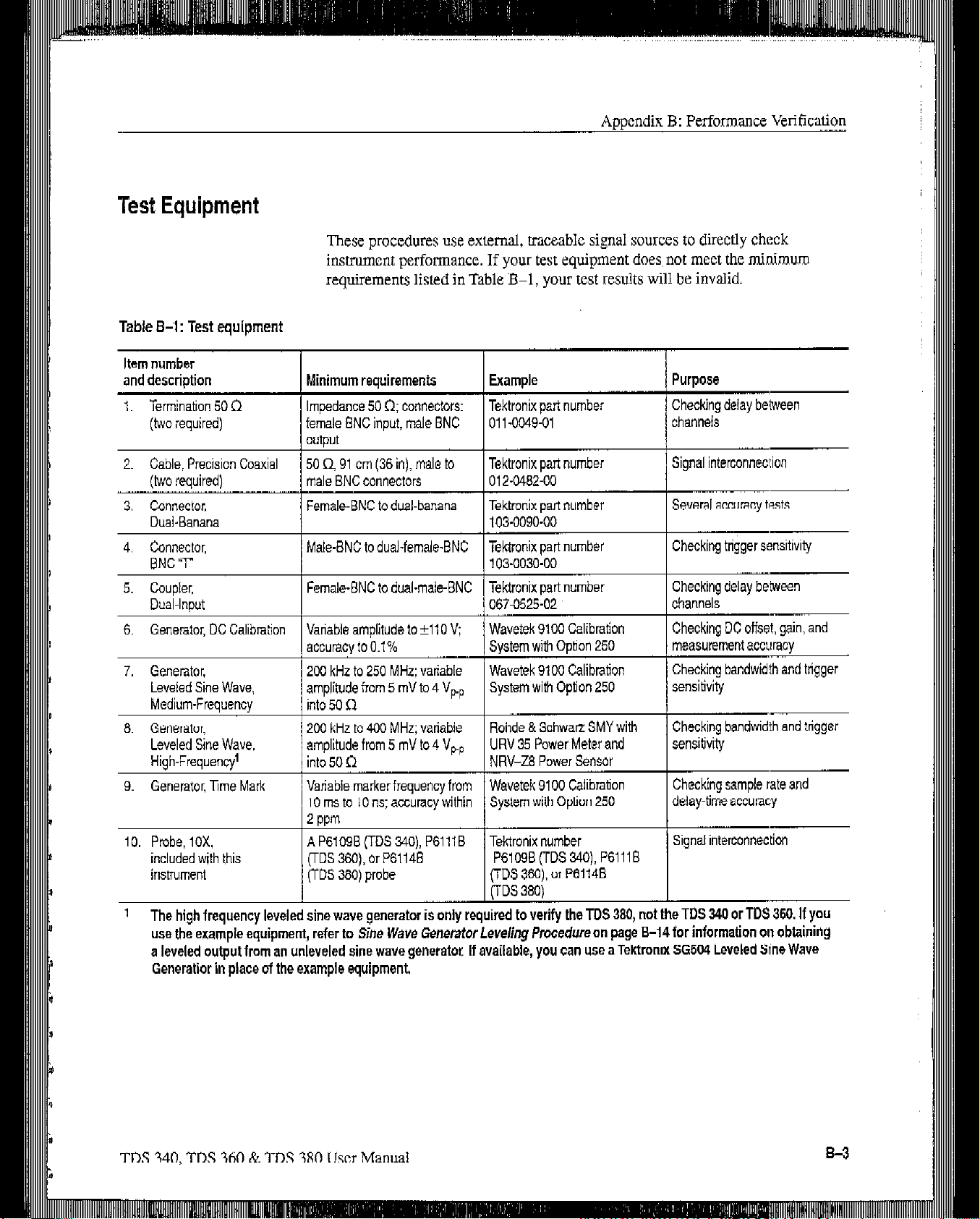
Test Equipment
These procedures use external, traceable signal sources to directly check
instrument perfotmancc. If your test equipment does, not meet the minimum
requirements listed in Table B-l, your test results will be invalid.
Table B-i: Test equipment
Item number
and description Minimum requirements Example Purpose
1. Termination 50 0
(two required) female ENC inpuf, male BNC 011-0049-01
2. Cable, Precision Coaxial
(Iwo required)
3. Connector,
D&Banana
4. Connector, Male-BNC to dual-female-BNC Tektronix part number Checking trigger sensitivity
BNCT 103-0030-00
5. Coupler, Female-ENC to dual-male-BNC Tektronix part number Checking delay
Dual-Input
6. Generator, DC Calibration Vanable amplitude to f110 V;
7. Generator, 200 kHz to 250 MHz: variable
Leveled Sine Wave,
Medium-Frequency
6. Generator, 200 kHz to 400 MHz; variable
Leveled Sine Wave, amplitude from 5 mV to 4 V,.,
High-Frequency’
9. Generator, lme Mark Variable marker frequency from Wavetek 9100 Calibration Checking sample rate and
Impedance 50 R; connectors: Tektronix pari number Checking
channels
50 0.91 cm (36 in), male to
male ENC connectors
Female-BNC to dual-banana
Tektronix part number
012-0462-00
Tektronix part number
103-0090-00
Signal interconnec!:ion
Several accuracy tests
delay belween
between
0670525-02
Wavetek 9100 Calibration Checking DC offset, gain, and
accurecy to 0.1% System with Oplion 250 measurement accuracy
Wavetek 9100 Calibration Checking bandwidth and trigger
amplitude from 5 mV to 4 Vpp
into 50 R
into 50 n
10 ms to 10 ns; accuracy within System with Option 250 delay-lime accuracy
System with Option 250
Rohde & Schwarr SMY with
URV 35 Power Meter and sensitivity
NRV-Z8 Power Sensor
channels
sensitivity
Checking bandwidth and trigger
10. Probe, 10X.
included with this FDS 360), or P6114E P6109B(TDS340),P6111E
instrument (TDS 360) probe
’ The high frequency leveled sine wave generator is only required to verify the TDS 380, not the TOS 340 or TDS 360. If you
use the example equipment, refer to
a leveled output from an unleveled sine wave generator, If available, you can use a Tektronix 56504 Leveled Sine Wave
Generatior in place of the example equipment.
A P6109B (TDS &IO), P6111B Tektronix number
(TDS 360). or P61148
FDS 380)
Sine
Wave Generator
Leveling
Procedure on page E-14 for information on obtaining
Signal interconnection
TDS 340, TDS 360 & ‘TDS 380 User Manual
Page 47

CH2 VOLTYDIV 1 V
Aat50mV +266 mV +314mV
10mV
5mV -982 mV -998 rnv
Analog bandwidth
CHI
GH2
Long term sample rate and delay time accuracy
Edge trigger sensitivity, DC coupled
Main Ttigger
Main Trigger-Falling
1
Generator set at -0.6 V.
2
Generator set at -0.9 V.
154.6 mV +65.4 mV
42.5 mV N/A
,42.5 mV
-2.0 Div +2.0 Div
stable trigger
stable trigger
N/A
N/A
N/A
: :;,;
B-4
Page 48

Performance Test Overview
The proccdurcs arc in three groupings: Signal Acquisition System Checks, ?ime
Bass System Checks, and Triggering System Checks. They check ah the
characteristics that appear in boldface type und&Warranted Characteristics on
page A-l.
Aooendix B: Pcrformarxc Verification
Prerequisites
The tests in this subsection comprise an extensive, valid confrrnation of
performance and functionality when the following requirements are met:
The cabinet must bc installed.
You must have performed and passed the procedures under Self Tests, on
page l-5 and those under Functional Tests, on page 1-7.
The digitizing oscilloscope must have been operating for a warm-up period
of at least 20 minutes, and must bc operating at an ambient tcrnperature
between -10” C and +5S” C.
Signal Acquisition System Checks
These procedures check signal acquisition system characteristics that are listed as
checked under Wurranted Characteris6ics in the Specifications
Check DC Voltage
Measurement Accuracy
WARNING. Pe~fom~ance of this procedure requires input voltages tip to 98 VUC.
!
n
Contact with live circuits could cause injury or death. Be sure to set the DC
calibration generator to 0 vah bcforc connecting, disconnecting, and/or moving
the test hookua durinz the oerformance ofchis orocedure.
sccl:ion.
Equipment Required: One dual-banana connector (Item 3). one DC calibration
generator (Item 6), and one precision coaxial cable (Item 2).
Time Required: Approximately 35 minutes.
Prerequisites: The oscilloscope must meet the prerequisites listed on
page B-5.
Procedure:
1. Set the output of a DC calibration generator to 0 volts.
TDS 340. TDS 360 & TDS 380 User Manual
B-5
Page 49

Appendix
-
B: Pcrformancc Verification
2. Connect the output of a DC calibration generator through a dual-banana
connector followed by a 50 8 precision coaxial cable to CII 1. as shown in
Figure B-2.
DC Calibrator
Coaxial cable
llllll/ i!
Figure B-2:
3.
Press
Factory Init.
4.
Press
5.
Press
6. Press tic side menu button
Hookup for DC voltage measurement accuracy check
SAVE/RECALL SETUP i Recall Factory Setup + OK Confirm
ACQUIRE -+ Mode + Average 16.
MEASURE -t Select Measurement.
more
undl UK menu label Mean appears in the
side menu. Press the side menu button Mean.
7. Set the
have
8. Press
9. Turn the
vertical SCALE
not yet checked. (Start with the first setting listed.)
VERTICAL MENU-t Position
General Purpose Knob
to one of the settings listed in Table E-2 that you
to set the vertical position to the setting
listed in Table B-2. The baseline level moves off screen.
10. Press the main
11. Use the General
menu button Offset.
Purpose
Knob to set
vertical offset to the setting listed in
‘fibk B-2 for the present vertical scale setting. The baseline level remains
off screen.
B-6
TDS 340, TDS 360 & TDS 380 User Manual
Page 50

3
n
,_-,
Table B-2: DC accuracy
Appendix
B: Performancr:
Va’ificution
Vertical scale Position
setting
1V
200 mV
50 mV
5mV
setting (divs) Offset settina settina Accuracv limits
I +5
I +5
I -5
IO
I +lOOV 1+98V 1+97-l
I*1ov I ea.4 v 1 t8.28
l-l v
l-l v
Generator
I-IXV
I -990 mV
V to t98.9 V
V to t8.52
I -581 mV to 419 mV
I
-982 mV to -998 mV
V
12. Set the generator to the level and polarity indicated in Table B-2 for the
vertical scale, position, and of&t settings you have made. The DC test level
should appear on screen. (Ifit dots not rctum, the DC accuracy cheek has
failed for the present vertical scale setting of the current channel.)
13. Check that the readout for the measurement Mean readout on screen is
within the limiti listed For the present vertical scale and position/offsct/gcnerator settings.
1,4.
Repeat steps 7 through 13 until you have checked all the vertical scale
settings listed in Table B-2. Record the measurements for each of the 50 mV
settings.
15. Subtract the second 50 mV measurement from the first and compare the
result to the
:16. Press WAVEFORM OFF;
17.
Set the generator output to 0 V.
“A at
50 mV” limits in Table B-2.
then, press CH 2
18. Move the test hookup to the CH 2 input.
19. Repeat steps 5 through I5 for channel 2.
20. Set the generator output to 0 V,
DC Gain Accuracy
2X. Disconnect the
DC gain accuracy is verified by successful completion of the
cable
at the
CH
2 input connector.
self tesI:s and the
DC voltage measurement accuracy (in the previous procedure).
Offset
Accuracy
Offset accuracy is verified by successful completion of the Self Tests and the DC
voltage measurement accuracy (in the previous proccdurc).
TDS 340, TDS 360 & ‘I’D.5 380 User Manual
B-7
i
Page 51

precision cable (Item Z),
Time Required: Approximately 20 minutes.
Prerequisites: See page B-5.
Procedure:
1. Connect, through a 50 !J precision cable and a 50 9 terminalion, the sine
wave output of a kvekd sine wave generator to CH 1 (see Figure B-3). Set
the output of the generator to a reference frequency of 50 Hz.
and
one 50 B termination (Item 1).
NOTE Iiyou
wit/z a 400
Procedure
unlcvekd sine uwe generam
Leveled
Sine
Wave
Generator
L
Figure B-3: Hookup for analog bandwidth check
1. Press SAVE/lZECAI,L SETUP + Recall Factory Setup -+ OK Confirm
Factory Init.
are
verifying a TDS 380, you need a leveled sine wave generator
MHz oztputfrequency.
on
page B-14
owul
jbr in@wation on obtaining a leveled
He&r
to
Sine Wave Generator Leveling
output&m, an
SO R Terminalion
b-
2. Set the horizontal SCALE JO 10 ps/div.
3. Press TRIGGER MENU -+ Coupling -+ Noise Rej.
4. Press ACQUIRE + Mode + Average X6.
5. Press MEASURE -+ High-Low Setup -+ Min-Mar.
6. Press the main menu button Select Measurement. Now press the side menu
button more until the
side menu button Pk-Pk.
7. Set the vertical SCALE to 10 mV/div.
menu
label Pk-Pk appears in the side
TDS 340, TDS 360 & TDS 380 User Manual
menu. Press the
Page 52

First. increase the reference
frequency ID
then decrease the horizontal
rhe fesl frequency;
scale.
Appendix B: Performance Verification
8. Set the generator output so the CHx Pk-Pk readout equals 60 :mV.
9. Press SET LEVEL TO 50% as necessary to trigger the display.
10. Increase the frequency of the generator output to 100 MHz (TDS 340),
200 MHz (TDS 360). or 400 MHz (TDS 380).
11. Set the horizontal SCALE to 5 ns/div (TDS 340), 2.5 ns/div (TDS 360), or
2.5 ns/div (TDS 380).
12. Press SET LEVEL TO 50% as necessary to trigger the display.
13. Cheek that the Pk-Pk readout on screen (as shown in
Figure B-l) is 2 42.5 mV
Second. read Ihe resutls
from the readout of
measuremenf Pk.Pk.
Figure B-4: Measuring analog bandwidth
14. When fmishcd checking, set the horizontal SCALE back to the 10 @div
setting, and set the generator output frequency back to 50 kHz.
15. Press WAVEFORM OFF to remove Channel 1 from the display.
16. Press CH 2 and move the hookup to the CH 2 input.
17. Press TRIGGER MENU + Source + CH 2.
18. Repeat steps 6 through 13 for CH 2.
Page 53

Appendix B: Performance Veritication
-,I_
19. Disconnect the test hook up from the CH 2 input
Time Base System Checks
This procedure chec!~ those characteristics that. relate to the Main and Delayed
time
base system and are listed as checked
the Spcci$cations section.
Check Long-Term Sample
Rate and Delay Time
Accuracy
Equipment Required: One time-marker generator (Item 9), one precision
coaxial cable, (Item 2) and one 50 Q termination (Item 1).
Time Required: Approximntcly 5 minutes.
Prerequisites: See page B-5.
Procedure:
1. Connect, through a 50 Q precision coaxial cable and a 50 Q termination, the
time-mtuk output of a time-marker generator to CH 1, as shown in Fibwe
B-5. Set the output of the generator for 10 ms markers.
connector.
under Warrankd Chamctoirtics
in
- SO II Termioafion
bl
Figure B-5: Hookup for sample rate check
2. Press SAVE/RECALL SETUP -+
Factory Init.
3.
Set the vertical SCALE to 500 mV/div.
4.
Press SET LEVEL TO ,SO%: use the vcrticti POSITION knob to center
the test signal on
screen.
5. Set the horizontal SCALE to 1 ms/div.
6.
PXSS HORIZONTAL MENU-t
Recall
Trigger
Factory Setup -+ OK Confirm
Position -t Set to 10%.
TDS 340, TDS 360 & TDS 380 User Manual
Page 54

Appendix B: Performance Vcrii%at,ion
7.
Adjust the horizontal POSITION to move the trigger T to the right and on
to the screen. Continue to position the trigger T to align it to the cenler
vertical gaticulc lint.
x.
Press the main menu button Time Rase; then press the side menu button
Delayed Only.
Set the hodzontal SCALE of the D (delayed) time base to 1 ms/div. Then
Y.
use chc General Purpose knob to set delay time to 10 ms.
‘10. Set the horizontal SCALE of the D (dclaycd) time base to 500 ns/div.
NOTE When you change the SECDIV in step 10, the delay time readout
changes to IO.00001 or 9.99999. This is normal and has rzza effect on the
verijication
11. Check that the rising edge of the marker crosses the center horizontal
graticule line at a point within ti.0 divisions of the gratlcule cerner.
NOTE One division ofdisplacementfrom the center graticule corresponds to
a SO ppm time base errox
12. Disconnect the test hookup.
Delta Time Measurement
Accuracy
Della time measurcmcnt accuracy is verified by successful completion of the
previous procedure.
Trigger System Checks
These procedures check those characteristics that relate to the trigger system and
are listed as checked under Warranted Characteristics in the Spccificacnlions
section
Check Edge Trigger
Sensitivity, DC Coupled
Equipment Required: One leveled sine wave gcncrator (Item 7 or 8), two
precision 50 SZ coaxial cables (Item 2), one 50 Q tcrmlnation (Item I), and one
BNC T connector (Item 4).
Time Required: Approximately 10 minutes.
Prerequisites: See page B-5.
TDS 340, TDS 360 & ‘IDS 380 User Manual
B-11
Page 55

Appendix B: Performance Verification
-,
1. Press SAVE/RECALL SETUP J Recall Factory Setup + OK Confrm
Factory Init.
2. Set the vertical SCALE to 500 mV/div.
3.
Set tie horizontal SCALE to 10 n&iv.
4.
Press TRIGGER MENU + Made -+
5. Press ACQUIRE -t Mode -+ Average 16.
6. Connect one 50 Q cable to the output of the sine wave generator. Attach a
BNC T connector tv the other end of the cable. Connect a second 50 Q cable
to the ocher side of the BNC T connector.
7.
Connect the BNC T connector to CH 1; connect tic cable to the EXT TRIG
input through a 50 9 termination as shown in Figure B-6.
Nnmal.
To Efl Trigger
50 n
Terrninah
Figure B-6:
8. Scr the generator frequency to 100
400 MHZ (TDS 3SO).
9.
Press MEASURE -t High-Low Setup -+ Min-Max
10. Press the main menu button Select
Hookup for
trigger sensitivity check
MHZ
(Trx 340). 200 MH;: (TDS 360). or
Measurement.
11. Press the side menu button -more- until Amplitude appears in the side
menu. Press the side menu button Amplitude.
12. Press SET LEVEL
TO
50%.
13. Set the test signal amplitude for about one division on screen, Fine adjust the
generator output until the CH I Amplitude readout indicates the amplitude
is 500 mV. (Readout may fluctuate around 500
mV)
14. Press TRKGGER MENU + Slope.
TDS 340, ‘IDS 360
& TDS 380 User Manual
Page 56

Second,
check for a Sable --
15. PKSS SET LEVEL TO 50%. Check that a stable trigger is obtained for the
test waveform on both the positjve and negative slopes (see Ei~ucc B-7).
(Use the side menu to switch between trigger slopes; use the trigger LEVEL
knob to stabilize the trigger if required.)
’ ’
,.
Figure B-7: Measuring trigger sensitivity
X6. Press WAVEFORM OFF.
17. Press CH 2.
1X. Press TRIGGER MENU + Source + Ch2.
19. Disconnect the hookup from CEI 1 and cormect it to CH 2.
20. Set the vertical SCALE to 500 mV/ciiv.
21. Repeat steps I4 and 15 for Channel 2.
22. Press TRIGGER MENU -3 Source + EXT/lO.
23. Press MEASURE + Select Measrmnt + Amplitude.
24. Incrcasc the generator amplitude until the amplitude measurement reads
1.5 V
if you are
checking a IDS 340 or TDS 360. Increase the generator
amplitude until the amplitude measurement reads 4.0 V if you are checking a
TDS 380.
Page 57

1,.
Connect the equipment as shown in Figure B-8.
2.
Set the sine wave generator to a reference frequency of 50 Wz.
B-14
3.
Adjust
me sine wave gcncramr amplitude to tic required number of
divisions as measured by the oscilloscope.
4.
Note the reading on the level meter.
5.
Change the sine wave generator to the desired new frequency.
6.
Input the correction factor for the new frequency into the level
I.
,&djuS[
the sine wave _~cncrabr amplitude until the level mMH
the value noted in step 4. The signal amplimde is now correctly set
new frequency.
TDS 310, ‘IDS 360 & TD:
meter.
again
Page 58

Appendix 6: Pcrfomance Vetification
Figure B-8: Hookup far sine wave generator leveling
‘IDS 340, TDS 360 8~ TDS 380 User Manual
Page 59

Options
This appendix dcscribcs the various options as well as the standard and optional
accessuries that are available for the TDS 340. TDS 340, and TDS 380.
Options include the following.
Option 14: l/O Interfaces
Options Ai-AS:
International Power Cords
This option includes GPIB, RS-232, and Centronics interfaces, VGA video
output, and power for the DPU 411 printer. It also includes the TDS 340,
TDS 360 & TDS 380 Programmer Manual.
You can connect a remote display to the VGA 9.pin D cotmccmr on the rear
panel. Table C-6 on page CA gives the part number of a properly shielded
cable that is commercially
available.
Because display manufacturers use diffcrcnt pin combinations and connectors,
you may find Ihe information in Table C-l helpful.
Table C-l: VGA output connector pins
Pin Signal
2 1 Video (monochrome analog)
4
5
6. 7.6
Besides the standard North American, 110 V, 60 Hz power cord, Tektronix
I
1 Horizontal sync @ 31.5 kHz (VGA rate)
I Vertical sync
I
Ground
ships
any of five alternate power cord configurations with the oscilloscope when
ordcrcd by the customer (see Table C-2).
TDS
340,
TDS
360
& TDS
Table C-2: International
Option
Al
A2
A3 Australian - 240 V, 50 Hz
380
user hhnUd
power cords
Power Cord
Universal European - 220 V, 50 Hz
UK - 240 V, 50 Hz
Page 60

Appendix C: Options and Accessories
-
Table C-2: international power cords (Cont.)
Language Options
Option
A4
Power Cord
North American - 240
V. 60 Hz
..
A5 Switzerland - 220 V, 50 Hz
Language options provide user documentation in following local languages (see
Table C-3 for options and manual part numbers):
Table C-3: Language options
Language option
Std
I”1
L3
L4
L5
L7
LR
LQ
/ Language
English
French
1 Gem-w
Spanish
Japanese
Simple Chinese
Standarc! Chinese
Korean
User
manual
/ 070-9459-u
070.9431 -xx
I 070-9432-u
07O+I33~xy
070-9440-Xx
070.Q&7-xx
,.~
070.9438-Xx
070.9439xX
Reference
070.94wxx
070.9441-XX
Warranty-Plus Service
Options
The k~hwin~ options add to the services available with the sYdndard, warranty.
(The standard warranty appears immediately following the title page in this
manual.)
n
Option M2: Tektronix provides tbrce years of warranty plus two years
remedial service.
n
Option M3: Tektronix
provides tbrce years of warranty plus two years
remedial service and four Oscilloscope calibrations.
n
Option
M8:
Tektronix provides four calibrations and four performance
verifications, one of each in the second through the fifth years of service.
TDS 340, ‘IDS 360 & TDS 380 User Manual
Page 61

Accessories
ional Accessories
The standard accessories listed in Table C-4 come with the TDS 340, TIE 360,
and TDS 380. (Refer to Table C-3 for manual
Table C-4: Standard accessories
ACCWOry
Reference
User Manual
U.S. Power Cord
Probes (quantity two) PGIOSB 10X Passive (TDS 340)
Probes (quantity two) P611lB 10X Passive (TDS 360)
Probes (quantihtwo) P6114B 10X Passive (TDS 380)
part
numbers.)
You can order the optional accessories listed in Table C-5.
Table C-5: Optional accessories
Accessory
Scope Camera
Oscilloscope Cart
Rackmount Kit (for field conversion) 016-1166-00
Soft-Sided Carrying Case
Carrying Case 016-0792-01
Deluxe Transit Case
Front Cover 200-3232-02
AccessonesPouch 016-1159.00
I/O Interface Field Upgrade Kit TD3F14A
Docuwave waveform capture utility software for the PC S60 DWAV
Printer, bubble-jet, 360 dpi, 63 cps, plain paper HC 220
Printer, portable thermal, 112 mm paper DPU 411
Paper for DPU 411 minter. package of five
Programmer Manual
Tolls
Part number
C9. Option 4, (includes Adapter
Hood 016-1154-01)
016-1156-01
016-1157~00
I 006-7560.00
1070.9442-xX
Service Manual I 070”9435-XX
Page 62

Appendix C: Options and Accessories
Accessory Probes
These arc other types of probes you can use with the TDDS 340, TDS 360, and
TDS
380. You
I P61OlB 1X Passive Probe
n
P6129B Switchable 1X-10X Passive Probe (not recommended for the
TDS 360 or TDS 380)
n
P6408 ‘IT Logic Probe
n
PS
100 High Voltage Probe
q
P5200 High-Voltage Differential Probe
can order the following probes separately:
Accessory Cables
m AM503S
DC/AC Current Probe System
m P6561AS SMD Small-Geometry Probe
Table C-6 lists
cables you can use
with the TDS 340, TDS 360, and ‘IDS 380.
You can order them separately.
Table C-6: Accessory cables
Cable type
GPIE.1 meter (3.3 feet)
GPIE, 2 meter (6.6 feet)
K-232, e-pin female to g-pin female connectors, null
modem, 76 inch (for AT style computers)
RS-232. g-pin female to 25pin female connectors, null
modem, 76 inch (for PC style compwers)
K-232, S-pin female to 25pin male connectors, null
modem, 9 feet (forserial interface plinks)
Part number
012-0991-01
012.1298-00
135-232. g-pin female to 25.pin male connectors, 15 feet
(for modems)
Centronics, 25.pin male to 36.pin Centronics,
2.4 meter (8 feet) (for parallel printer interfaces)
NEW VGA video cable. (Use an appropriate adapter
when other than a e-pin monitor connection is needed.)
TDS 340, TDS 360 & TDS 380
012.1214-00
User ManUd
Page 63

General Care and Cleaning
D:
Protect tic oscilloscope from adverse weather conditions. The oscilloscope is not
waterproof.
CAUTION. To avoid damage to the oscilloscope, do not expose it to sprays,
!
A
liauids. or solvennt~.
!
A
Inspect the oscilkcope as often as operating
oscilloscope exterior, perform the following steps:
1.
Remove loose dust on the outside of the oscilloscope with a lint-free cloth.
Use care to avoid scratching tic clear plastic display filter.
Use a soft cloth or paper towel dampcncd with water to clean the oscillo-
2.
scope. You can use a 75% isopropyl alcohol solution for more efficient
cleaning.
CAUTION. i71 awid damage to the surfhce of the oscilloscope, do not USL’ nny
abrasive or chemical cleaninn apent,s.
COnditionS rCqUire.
To clean the
3&l DS 380 User Mz
mual
 Loading...