

Page 1

xx
TCPA300/400 Amplifiers &
ZZZ
TCP300A/400 Series AC/DC Current Probes
User Manual
*P077118301*
077-1183-01
Page 2

Page 3

xx
TCPA300/400 Amplifiers &
ZZZ
TCP300A/400 Series AC/DC Current Probes
User Manual
This document applies for firmware version 1.0 and above.
www.tektronix.com
077-1183-01
Page 4

Copyright © Tektronix. All rights reserved. Licensed software products are owned by Tektronix or its subsidiaries
or suppliers, and are protected by national copyright laws and international treaty p rovisions.
Tektronix products are covered by U.S. and foreign patents, issued and pending. Information in this publication
supersedes that in all previously published material. Specifications and price change privileges reserved.
TEKTRONIX and TEK are registered trademarks of Tektronix, Inc.
Additional trademark statements can be added here.
Contacting Tektronix
Tektronix, Inc.
14150 SW Karl Braun Drive
P.O . B ox 5 0 0
Beaverton, OR 97077
USA
For product information, sales, service, and technical support:
In North America, call 1-800-833-9200.
Worl d wid e, v i si t www.tektronix.com to find contacts in your area.
Page 5

Warranty
Tektronix warrants that this product will be free from defects in materials and workmanship for a period of one (1)
year from the date of shipment. If any such product proves defective during this warranty period, Tektronix, at its
option, either will repair the defective product without charge for parts and labor, or will provide a replacement
in exchange for the defective product. Parts, modules and replacement products used by Tektronix for warranty
work may be n
the property of Tektronix.
ew or reconditioned to like new performance. All replaced parts, modules and products become
In order to o
the warranty period and make suitable arrangements for the performance of service. Customer shall be responsible
for packaging and shipping the defective product to the service center designated by Tektronix, with shipping
charges prepaid. Tektronix shall pay for the return of the product to Customer if the shipment is to a location within
the country in which the Tektronix service center is located. Customer shall be responsible for paying all shipping
charges, duties, taxes, and any other charges for products returned to any other locations.
This warranty shall not apply to any defect, failure or damage caused b y improper use or improper or inadequate
maintenance and care. Tektronix shall not be obligated to furnish service under this warranty a) to repair damage
result
b) to repair damage resulting from improper use or connection to incompatible equipment; c) to repair any damage
or malfunction caused by the use of non-Tektronix supplies; or d) to service a product that has been modified or
integrated with other products when the effect of such modification or integration increases the time or difficulty
of servicing the product.
THIS WARRANTY IS GIVEN BY TEKTRONIX WITH RESPECT TO THE PRODUCT IN LIEU OF ANY
OTHER WARRANTIES, EXPRESS OR IMPLIED. TEKTRONIX AND ITS VENDORS DISCLAIM ANY
IMPLIED WARRANTIES OF MERCHANTABILITY OR FITNESS FOR A PARTICULAR PURPOSE.
TRONIX' RESPONSIBILITY TO REPAIR OR REPLACE DEFECTIVE PRODUCTS IS THE SOLE
TEK
AND EXCLUSIVE REMEDY PROVIDED TO THE CUSTOMER FOR BREACH OF THIS WARRANTY.
TEKTRONIX AND ITS VENDORS WILL NOT BE LIABLE FOR ANY INDIRECT, SPECIAL, INCIDENTAL,
OR CONSEQUENTIAL DAMAGES IRRESPECTIVE OF WHETHER TEKTRONIX OR THE VENDOR HAS
ADVANCE NOTICE OF THE POSSIBILITY OF SUCH DAMAGES.
[W2 – 15AUG04]
btain service under this warranty, Customer must notify Tektronix of the defect before the expiration of
ing from attempts by personnel other than Tektronix representatives to install, repair or service the product;
Page 6

Page 7

Table of Contents
General safety summary ...... .................................. ................................ ................... v
Compliance Information......................................................................................... vii
EMC Compliance (Applies to TCPA300 & TCPA400 Amplifiers Only) .... ......................... vii
Safety Compliance Information....................... ................................ ..................... viii
Environmental Considerations .......... ................................ ................................ ..... x
Preface .............................................................................................................. xi
Manual Conventions............................................ ................................ .............. xi
Getting Started .. .. .. . .. .. .. . .. .. .. . .. .. .. . .. .. .. . .. .. .. . .. .. .. . .. .. .. . .. .. .. . .. .. .. . .. .. .. . .. .. .. . .. .. .. . .. .. .. . .. .. 1
System Configuration ......................................................................................... 1
Options.......................................................................................................... 3
Standard Accessories.......................................................................................... 4
Optional Accessories .......................................................................................... 4
Probe Cover ..... ................................ ................................ ............................... 5
Ground Lead ...................... .................................. ................................ ........... 6
Travel Case .......................... ................................ ................................ ........... 7
Connecting the Amplifier to an Oscilloscope.. . .. .. .. . .. .. .. . .. .. .. . .. .. .. . .. .. . .. .. .. .. . .. .. . .. .. .. .. . .. .. 8
Power on the Amplifier ............ ................................ .................................. ......... 8
nnecting a Current Probe to the Amplifier...................... .................................. ....... 9
Co
Operating the Current Probe Slide.......................................................................... 10
Degaussing and Autobalancing the Current Probe........................................................ 12
DC Measurements ............................................................................................ 13
AC Measurements ............................................................................................ 15
Control Summary...................... .................................. ................................ .......... 17
TCPA300 and TCPA400 Controls .......................................................................... 18
Reference Notes ................................................................................................... 23
Degaussing a Probe with an Unpowered Conductor in the Jaws ........................................ 23
Measuring Differential Current ............................................................................. 24
AC and DC Coupling......................... .................................. .............................. 26
Maximum Current Limits.............. .................................. ................................ .... 27
Measuring Noncontinuous Current with the TCP404XL Probe......................................... 30
Extending Current Range.................................................................................... 32
Increasing Sensitivity. .. .. .. . .. .. .. . .. .. .. .. . .. .. .. . .. .. .. . .. .. .. . .. .. .. . .. .. .. . .. .. .. .. . .. .. .. . .. .. .. . .. .. .. . 34
Application Notes ................................................................................................. 35
Automobile Charging Systems .............................................................................. 35
Inductance Measurements . ................................ .................................. ................ 37
Continuity Test of Multiple-Conductor Cable .. . .. .. .. . .. .. .. . .. .. .. . .. .. .. . .. .. .. .. . .. .. .. . .. .. .. . .. .. .. . 39
Measuring Inductor Turns Count . ................................ .................................. ........ 40
Power Measurement and Analysis Software......................... .................................. .... 41
TCPA300/400 Amplifiers and TCP300A/400 Series Current Probes User Manual i
Page 8

Table of Contents
Troubleshooti
Displaying Error Codes with the Probe Degauss Autobalance Button ........... ...................... 45
Correcting the Cause of an Error Code........... ................................ .......................... 47
Shutdown Error . ................................ ................................ .............................. 47
Specifications .......... ................................ ................................ ............................ 49
Warranted Specifications..................................................................................... 49
Nominal and
Mechanical Characteristics .................................................................................. 51
Environmental Characteristics .............................................................................. 53
Performance Graphs .............................. .................................. .......................... 54
TCP404XL Maximum Measurement Times..................................... .......................... 58
Glossary
Index
ng and Error Codes.......................... ................................ ...................... 42
Typical Characteristics ..... ................................ .................................. 50
ii TCPA300/400 Amplifiers and TCP300A/400 Series Current Probes User Manual
Page 9

List of Figures
Figure 1: Typical TCPA300/400 current measurement system............................... ................. 1
Figure 2: Using the probe cover ................. ................................ ................................. 5
Figure 3: Connecting the ground lead ................ .................................. ......................... 6
Figure 4: Equipment locations in the travel case ............................................................... 7
Figure 5: Connecting and disconnecting a current probe to the amplifier.................................... 9
Figure 6: TCP312A and TCP305A slide operation...................... .................................. .... 10
Figure 7: Unlock and open the TCP303 and TCP404XL ................... ................................ .. 11
Figure 8: Close and lock the TCP303 and TCP404XL........................................................ 11
Figure 9: Arrow on current probe indicates conventional current flow ..................................... 14
Figure 10: The TCPA300 front panel ................. ................................ .......................... 17
Figure 11: Measuring two conductors........................................................................... 24
Figure 12: Measuring differential current and nulls ........................................................... 25
Figure 13: Effect of AC or DC coupling on low-frequency signals .. .. . .. .. .. . . . .. .. . .. .. .. .. . .. .. .. . .. .. .. 26
Figure 14: Applying the amp-second product rule .. .................................. ........................ 28
Figure 15: Duty cycle calculation ............. .................................. ................................ 30
Figure 16: Adding a second conductor............................ ................................ .............. 33
Figure 17: Adding multiple turns................................................................................ 33
Figure 18: Increasing probe sensitivity .. .. .. . .. .. .. .. . .. .. . . . .. .. .. . .. .. .. . .. .. .. .. . .. .. . . . .. .. .. . .. .. .. . .. .. .. 34
Figure 19: Setup for measuring charging current................ ................................ .............. 36
Figure 20: Charge current waveforms..... ................................ .................................. .... 36
Figure 21: Measuring inductance with a low-impedance source............................................. 37
Figure 22: Linear current vs. time ramp ........................................................................ 38
Figure 23: High-impedance source current ramp .............. ................................ ................ 39
Figure 24: Measuring the number of turns in a coil ..... ................................ ...................... 40
Figure 25: Turns measurement using reference coil........................................................... 40
Figure 26: Error code d
Figure 27: Interpreting the error code display................ ................................ .................. 46
Figure 28: Probe jaw dimensions (nominal).... ................................ ................................ 52
Figure 29: Frequency derating-TCP312A ...................................................................... 54
Figure 30: Frequency derating-TCP305A ...................................................................... 54
Figure 31: Frequency derating-TCP303 ................ .................................. ...................... 54
Figure 32: Frequency derating-TCP404XL .... .................................. .............................. 55
Figure 33: Insertion impedance versus frequency ............................................................. 56
Figure 34: Specified operating area of the probes ............................................................. 57
Figure 35: Measuring 750A noncontinuous at 50 °C ambient temperature................................. 58
Figure 36: Measuring 600A noncontinuous at 50 °C ambient temperature................................. 58
Figure 37: Measuring 750A noncontinuous at 23 °C ambient temperature................................. 59
isplay .... .................................. ................................ .............. 45
TCPA300/400 Amplifiers and TCP300A/400 Series Current Probes User Manual iii
Page 10

Table of Contents
List of Tables
Table 1: Safety compliance information ....................................................................... viii
Table 2: Amp
Table 3: Service options ................ .................................. ................................ ......... 3
Table 4: Unpowered circuit degauss limits ..................................................................... 23
Table 5: Automobile charging systems test setup............ ................................ .................. 35
Table 6: Troubleshooting ............. ................................ .................................. .......... 42
Table 7: Amplifier error codes ....... .................................. ................................ .......... 46
Table 8: W
Table 9: Nominal and typical amplifier characteristics........................................................ 50
Table 10: TCPA300 and TCPA400 mechanical characteristics ............ ................................ .. 51
Table 11: Probe mechanical characteristics......................... ................................ ............ 52
Table 12: Shipping weights and dimensions ................................................................... 52
Table 13: Environmental characteristics ........................................................................ 53
lifier options...................... .................................. ................................ . 3
arranted TCPA300 and TCPA400 specifications................................ .................. 49
iv TCPA300/400 Amplifiers and TCP300A/400 Series Current Probes User Manual
Page 11

General safety summary
General safet
To avoid fire or personal
injury
y summary
Review the fo
this product or any products connected to it.
To avoid pot
Only qualified personnel should perform service procedures.
While using this product, you may need to access other parts of a larger system.
Read the safety sections of the other component manuals for warnings and
cautions r
Use proper power cord. Use only the power cord specified for this product and
certified for the country of use.
Connect and disconnect properly. Do not connect or d isconnect probes or test
leads while they are connected to a voltage source.
Connect and disconnect properly. Connect the probe output to the measurement
instrument before connecting the probe to the circuit under test. Connect the
probe reference lead to the circuit under test before connecting the probe input.
Disconnect the probe input and the probe reference lead from the circuit under test
before disconnecting the probe from the measurement instrument.
llowing safety precautions to avoid injury and prevent damage to
ential hazards, u se this product only as specified.
elated to operating the system.
Ground the product. This product is grounded through the grounding conductor
of the power cord. To avoid electric shock, the grounding conductor must be
nected to earth ground. Before making connections to the input or output
con
terminals of the product, ensure that the product is properly grounded.
erve all terminal ratings. To avoid fire or shock hazard, observe all ratings
Obs
and markings on the product. Consult the product manual for further ratings
information before making connections to the product.
Connect the probe reference lead to earth ground only.
o not connect a current probe to any wire that carries voltages above the current
D
probe voltage rating.
Do not operate without covers. Do not operate this product with covers or panels
removed.
Do not operate with suspected failures. If you suspect that there is damage to this
product, have it inspected by qualified service personnel.
Avoid exposed circuitry. Do not touch exposed connections and components when
power is present.
TCPA300/400 Amplifiers and TCP300A/400 Series Current Probes User Manual v
Page 12
General safety summary
Termsinthismanual
Symbols and terms on the
product
Do not operate i
Do not operate in an explosive atmosphere.
Keep product surfaces clean and dry.
Provide prop
on installing the product so it has proper ventilation.
These terms may appear in this manual:
WARNING.
in injury or loss of life.
CAUTION
damage to this product or other property.
These t
erms may appear on the product:
DANGER indicates an injury hazard immediately accessible as you read
the ma
n wet/damp conditions.
er ventilation. Refer to the manual's installation instructions for details
Warning statements identify conditions or practices that could result
. Caution statements identify conditions or practices that could result in
rking.
WARNING indicates an injury hazard not immediately accessible as you
the marking.
read
CAUTION indicates a hazard to property including the product.
The following symbol(s) may appear on the product:
vi TCPA300/400 Amplifiers and TCP300A/400 Series Current Probes User Manual
Page 13
Compliance Information
This section lists the EMC (electromagnetic compliance) and environmental
standards with which the instrument complies.
EMC Compliance (Applies to TCPA300 & TCPA400 Amplifiers Only)
EC Declaration o f
Conformity
–EMC
Meets intent of Directive 2004/108/EC for Electromagnetic Compatibility.
Complianc
e was demonstrated to the following specifications as listed in the
Official Journal of the European Communities:
EN 61326-1:2006, EN 61326-2-1:2006. EMC requirements for electrical equipment
for measurement, control, and laboratory use.
123
CISPR 11:2003. Radiated and conducted emissions, Group 1, Class A
IEC 61000-4-2:2001. Electrostatic discharge immunity
IEC 61000-4-3:2002. RF electromagnetic field immunity
IEC 610
00-4-4:2004. Electrical fast transient/burst immunity
IEC 61000-4-5:2001. Power line surge immunity
IEC 61000-4-6:2003. Conducted RF immunity
IEC 61000-4-11:2004. Voltage dips and interruptions immunity
4
EN 61000-3-2:2006. AC power line harmonic emissions
EN 61000-3-3:1995. Voltage changes, fluctuations, and flicker
European Contact.
Tektronix UK, Ltd.
Western Peninsula
estern Road
W
Bracknell, RG12 1RF
United Kingdom
1
This product is intended for use in nonresidential areas only. Use in residential areas may cause electromagnetic
interference.
2
Emissions which exceed the levels required by this standard may occur when this equipment is connected to a
test object.
3
To ensure compliance with the EMC standards listed here, high quality shielded interface cables should be used.
4
Performance Criterion C applied at the 70%/25 cycle Voltage-Dip and the 0%/250 cycle Voltage-Interruption test
levels (IEC 61000-4-11).
TCPA300/400 Amplifiers and TCP300A/400 Series Current Probes User Manual vii
Page 14

Compliance Information
Australia / New Zealand
Declaration of
Conformity – EMC
Complies with t
following standard.
CISPR 11:2003
he EMC provision of the Radiocommunications Act per the
. Radiated and Conducted Emissions, Group 1, Class A, in
accordance with EN 61326-1:2006 and EN 61326-2-1:2006.
FCC–EMC
Emissions are within the limits of FCC 47 CFR, Part 15, Subpart B for Class A
equipment.
Safety Compliance Information
Table 1: S
Category Standards or description
EC Declaration o f Conformity – Low
Voltage
U.S. Nationally Recognized Testing
Laboratory Listing
Cana
Add
stallation (Overvoltage) Category
In
Descriptions
afety compliance information
1
dian Certification
itional Compliance
Compliance was demonstrated to the following specification as listed in the Official Journal
of the European Communities:
Low Volt
EN 61010-1/A2:1995. Safety requirements for electrical equipment for measurement
control and laboratory use.
EN 6101
measurement and test equipment.
UL3111-1. Standard for electrical measuring and test equipment.
UL3111-2-032. Hand-held probe assemblies for electrical measurement and test.
UL610
laboratory use.
UL61010B-2-032: Particular requirements for hand-held current clamps for electrical
measu
CAN/
measurement, control, and laboratory use.
CAN/CSA C22.2 No. 61010.2.032:1996. Particular requirements for hand-held probe
ass
IEC
measurement and test.
IEC 61010-1:2001. Safety requirements for electrical equipment for measurement control
an
Te
designations. The installation categories are:
CAT III. Distribution-level mains (usually permanently connected). Equipment at this level is
t
CAT II. Local-level mains (wall sockets). Equipment at this level includes appliances,
portable tools, and similar products. Equipment is usually cord-connected.
C
age Directive 73/23/EEC, amended by 93/68/EEC.
0-2-032:1995. Particular requirements for hand-held current clamps for electrical
10-1. Safety requirements for electrical equipment for measurement, control, and
rement and test.
CSA C22.2 No. 61010.1. Safety requirements for electrical equipment for
emblies for electrical measurement and test equipment.
61010-2-032:1995. Particular requirements for hand-held current clamps for electrical
d laboratory use.
rminals on this product may have different installation (overvoltage) category
ypically in a fixed industrial location.
AT I. Secondary (signal level) or battery operated circuits of electronic equipment.
viii TCPA300/400 Amplifiers and TCP300A/400 Series Current Probes User Manual
Page 15

Compliance Information
Table 1: Safety compliance information (cont.)
Category Standards or description
Pollution Degree Descriptions
Equipment Type Test and measuring
Safety Class Class 1 (as defined in IEC 61010-1, Annex H) – grounded product
Overvoltage Category Overvoltage Category II (as defined in IEC 61010-1, Annex J)
Pollution Degree
1
The TCP305A and TCP312A Current Probes are exempt from the Low Voltage Directive and are not third-party listed. However, they have been evaluated to
applicable safety standards.
A measure of the contaminates that could occur in the environment around and within a
product. Typically the internal environment inside a product is considered to be the same
as the external. Products should be used only in the environment for which they are rated.
Pollution Degree 1. No pollution or only dry, nonconductive pollution occurs. Products in
this category are generally encapsulated, hermetically sealed, or located in clean rooms.
Pollution Degree 2. Normally only dry, nonconductive pollution occurs. Occasionally a
temporary conductivity that is caused by condensation must be expected. This location
is a typical office/home environment. Temporary condensation occurs only when the
product is out of service.
Pollution Degree 3. Conductive pollution, or dry, nonconductive pollution that becomes
conductive due to condensation. These are sheltered locations where neither temperature
nor humidity is controlled. The area is protected from direct sunshine, rain, or direct wind.
Pollution Degree 4. Pollution that generates persistent conductivity through conductive
dust, rain, or snow. Typical outdoor locations.
Pollution Degree 2 (as defined in IEC 61010-1). Note: Rated for indoor use only.
TCPA300/400 Amplifiers and TCP300A/400 Series Current Probes User Manual ix
Page 16
Compliance Information
Environmenta
l Considerations
Product End-of-Life
Handling
Restriction of Hazardous
Substances
This section provides information about the environmental impact of the product.
Observe the following guidelines when recycling an instrument or component:
Equipment Recycling. Production of this equipment required the extraction and
use of natural resources. The equipment may contain substances that could be
harmful to
end of life. In order to avoid release of such substances into the environment and
to reduce the use of natural resources, we encourage you to recycle this product
in an appropriate system that will ensure that most of the materials are reused or
recycled appropriately.
This product is classified as an industrial monitoring and control instrument
accessory, and is not required to comply with the substance restrictions of the
recast RoHS Directive 2011/65/EU until July 22, 2017.
the environment or human health if improperly handled at the product’s
This sym
Union requirements according to Directives 2002/96/EC and 2006/66/EC
on waste electrical and electronic equipment (WEEE) and batteries. For
informa
Tektronix Web site (www.tektronix.com).
bol indicates that this product complies with the applicable European
tion about recycling options, check the Support/Service section of the
x TCPA300/400 Amplifiers and TCP300A/400 Series Current Probes User Manual
Page 17

Preface
This User Manual supports the operation and basic maintenance of the TCPA300
and TCPA400 Current Probe Amplifiers, and the TCP300/400 Series AC/DC
current prob
manual are listed below:
es that mate with the amplifiers. The current probes covered in this
Service Manual
TCP312A (30
TCP305A (50 A, 50 MHz, compatible with TCPA300)
TCP303 (150 A, 15 MHz, compatible with TCPA300)
TCP404XL (500 A*, 2 MHz, compatible with TCPA400) *750 A DC derated
with duty cycle
If you are not familiar with these products, please refer to the Getting Started and
Operating Basics chapters of this manual for basic operating information.
If you are an advanced user, the Reference section contains information on
advanced applications as well as user diagnostic and troubleshooting information.
The Glossary and Index are provided as quick reference locators for important
information.
The Performance Verification and Adjustment procedures are located in the
Service Manual and support the qualification and calibration of the probes when
used with either amplifier.
The Maintenance section is also located in the Service Manual and supports the
routine maintenance and repair of mechanical parts associated with the amplifiers.
A, 100 MHz, compatible with TCPA300)
nual Conventions
Ma
The term "amplifier" is used to refer to either the TCPA300 or TCPA400 when
referring to common attributes. If a subject is unique to either amplifier, the
mplifier will be referred to directly by model.
a
The terms "current probe" and "probe" are used to refer to any of the TCP300A/400
Series current probes when referring to common attributes. If a subject is unique
to a particular probe, the probe will be referred to directly by model.
TCPA300/400 Amplifiers and TCP300A/400 Series Current Probes User Manual xi
Page 18

Preface
xii TCPA300/400 Amplifiers and TCP300A/400 Series Current Probes User Manual
Page 19
Getting Started
The TCPA300 and TCPA400 current probe amplifiers let you use one probe to
simultaneously measure AC and DC current. The amplifiers convert the sensed
current into
oscilloscope.
a p roportional voltage signal that you can measure directly with an
em Configuration
Syst
The TCPA300
than other current measurement systems because of a current feedback process
used with the probe. DC measurement capability and high bandwidth allow the
amplifiers to accurately represent square waves and fast-rise signals.
The TCPA300 and TCPA400 amplifiers and associated probes provide these
features:
Simultaneous DC and AC current measurements up to 750 A peak
High sensitivity
One-bu
No adjustments needed to match a current probe to an individual amplifier
AC or DC coupling of signal
Direct scaling and unit readout on compatible TEKPROBE level II
oscilloscopes
A complete current measurement system consists o f a current probe amplifier, a
compatible current probe, and an appropriate oscilloscope. (See Figure 1.)
and TCPA400 current probe amplifiers provide better linearity
tton autobalancing and probe degaussing
Figure 1: Typical TCPA300/400 current measurement system
1. 50 Ω oscilloscope input — use the TEKPROBE Interface Cable or use a
50 Ω cable. (Add a 50 Ω termination here if the oscilloscope only has a
high-impedance input).
TCPA300/400 Amplifiers and TCP300A/400 Series Current Probes User Manual 1
Page 20
Getting Started
TCPA300 and TCPA400
Current Probe Amplifiers
Current P robes
Oscilloscope
The amplifier am
plifies the current sensed by the probe and converts the current
to a proportional voltage that is displayed on an oscilloscope or other similar
measuring device.
The followin
g Tektronix current probes are compatible with the
TCPA300 Amplifier:
TCP312A (30
A, 100 MHz)
TCP305A (50 A, 50 MHz)
TCP303 (150 A, 15 MHz)
The following Tektronix current probes are compatible with the
TCPA400 Amplifier:
TCP404XL (750 A1,2MHz)
1
500 A continuous, 750 A DC derated with duty cycle
An osci
lloscope displays the output from the current measuring system. A 50 Ω
cable is included to connect the amplifier to the oscilloscope input channel. A
TEKPROBE-to-TEKPROBE interface cable is also included for connecting to
TEKPROBE level II oscilloscopes.
If the oscilloscope does not have an input that can be set to 50 Ω impedance, you
need a feedthrough 50 Ω termination. This termination is included as a standard
accessory with your TCPA300 and TCPA400 Current Probe Amplifiers.
2 TCPA300/400 Amplifiers and TCP300A/400 Series Current Probes User Manual
Page 21
Options
Getting Started
Table 1-1 lists options that are available for the TCPA300 and TCPA400
amplifiers.
Tabl e 2: Amp
Option Description
A1 Universal E
A2 United Kingdom power cord
A3 Australia power cord
A5
A6 Japan pow
AC China po
A99 No power cord
lifier options
uro power cord
Switzerland power cord
er cord
wer cord
Tektronix service options that you can order for your amplifiers and probes are
in this section. (See Table 3.) Designed to support tracking of calibration
listed
to requirements of ISO9000 a nd to provide for extended repair coverage, these
options help fix your long-term maintenance costs and eliminate unplanned
expenditures. Tektronix Service Options are available at the time you order your
instrument. Contact your local Tektronix Sales Office for more information.
Table 3: Service options
Option Description
D1
C3 Provides factory calibration certification on delivery, plus two more years of calibration coverage. Throughout the
D3
R3
C5 Provides factory calibration certification on delivery, plus four more years of calibration coverage. Throughout the
D5
R5
SILV400 Standard warranty extended to 5 years (TCP305A, TCP312A, TCPA300 and TCPA400)
SILV600 Standard warranty extended to 5 years (TCP303 and TCP404XL)
Provides the initial Test Data Report from the factory o n delivery.
coverage period, the instrument will be calibrated according to its Recommended Calibration Interval.
Provides test data on delivery plus a Test Data Report for every calibration performed during three years of coverage
(requires Option C3).
Extends product repair warranty to a total of three years.
coverage period, the instrument will be calibrated according to its Recommended Calibration Interval.
Provides test data on delivery plus a Test Data Report for every calibration performed during five years of coverage
(requires Option C5).
Extends product repair warranty to a total of five years.
TCPA300/400 Amplifiers and TCP300A/400 Series Current Probes User Manual 3
Page 22
Getting Started
Standard Acce
Amplifiers
ssories
Probes
The following accessories are shipped with the amplifiers and probes.
The following accessories are shipped with the TCPA300 and TCPA400
amplifiers.
Power Cord (customer-chosen option)
BNC Cable
Terminat i
TEKPROBE Interconnect Cable
Documentation CD (Includes User Manual–English, Japanese, and Russian
languages, and Service Manual–English only)
Certificate of Traceable Calibration
When you order a current probe, you will receive these accessories:
Probe cover (TCP303 and TCP404XL only)
Probe
on, 50 Ω 2W
ground lead, 6 inch length (TCP305A and TCP312A only)
ional Accessories
Opt
Instruction Sheet
Certificate of Traceable Calibration
You can order the following optional accessories for the amplifiers and probes.
One-turn 50 Ω HF current loop. Two versions are available; one for ea ch
style of probe. The current loops are used in the performance verification
procedures for checking the performance of the TCPA300 Amplifier and
he compatible probes.
t
TCPA Calibration Adapter. Use the TCPA Calibration Adapter to verify the
amplifier(s) p erformance independent of the current probes.
Travel Case. The travel case includes room to store one amplifier and two
current probes, along with related cables and adapters.
Deskew Fixture. This fixture converts the PROBE COMPENSATION output
or TRIGGER OUTPUT of the TDS5000 or TDS7000 into a set of test point
connections that allow you a convenient way to compensate for timing
differences between voltage and current probes.
4 TCPA300/400 Amplifiers and TCP300A/400 Series Current Probes User Manual
Page 23
Probe Cover
Getting Started
The TCP400 Series Current Probes come with a probe cover that stores the probe
when not in use. Use the probe cover to hold your probe in a convenient place at
your bench or
cover to the side of the bench to keep the probe off of your work surface. (See
Figure 2.)
workstation when you are not using it. You can attach the probe
Figure 2: Using the probe cover
TCPA300/400 Amplifiers and TCP300A/400 Series Current Probes User Manual 5
Page 24
Getting Started
Ground Lead
The TCP305A and TCP312A probes include a 6-inch ground lead. The ground
lead grounds the shield around the probe transformer at the probe end of the
cable. This a
measuring, thereby improving high frequency shielding. The ground lead clips
onto the ground connector on the bottom of the probe.
llows you to move the ground connection closer to the circuit you are
Figure 3: Connecting the ground lead
The ground lead on the current probes is intended to be used in high dV/dt
environments. The probes have a grounded shield between the conductor under
test and the current sense transformer. Any capacitively-coupled current will then
flow in the ground instead of the transformer windings.
When you take high frequency measurements, connect the probe ground lead to
the probe ground connector and attach the alligator clip directly to RF ground to
improve EMI rejection at high frequencies (2 MHz and above). This will reduce
nging and help bypass capacitively-coupled RF currents which can flow into
ri
the probe cable. In some cases, it may be helpful to move the ground lead or
reposition the probe away from noise sources in the circuit under test.
6 TCPA300/400 Amplifiers and TCP300A/400 Series Current Probes User Manual
Page 25
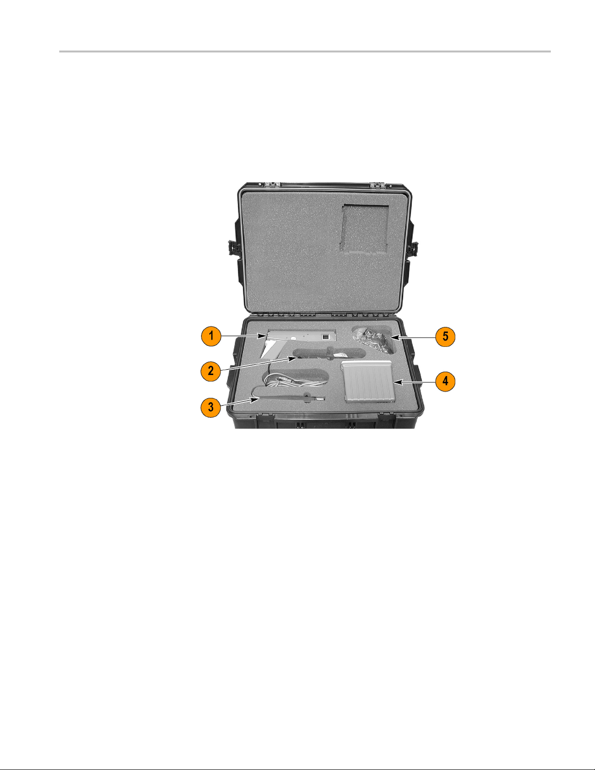
Travel Case
Getting Started
The travel case is a recommended accessory for the TCPA300/400 Amplifiers.
The travel case includes room to store one amplifier and two TCP300A/400 Series
Current Prob
a TCP303 probe.) A compartment is included to store associated cables and
terminations. (See Figure 4.)
es, one of each size. (For example, you can store a TCP305A and
re 4: Equipment locations in the travel case
Figu
1. Larg
2. Probe holders
3. Small current probe
4. Amplifier
5. Cables and terminations
TCPA300/400 Amplifiers and TCP300A/400 Series Current Probes User Manual 7
e current probe
Page 26

Getting Started
Connecting th
eAmplifier to an Oscilloscope
You will need an oscilloscope to display the TCPA300 and TCPA400 measurement
output. To use the full dynamic range of the probe/amplifier combination, the
oscilloscop
1 V/div.
If you are us
TEKPROBE-to-TEKPROBE interface cable. Otherwise, use the supplied
50 Ω BNC cable to connect the amplifier OUTPUT connector to your oscilloscope.
(SeeFigure1onpage1.)
The input impedance of the oscilloscope channel must be 50 Ω, or you will
encounter slowed pulse response, increased aberrations, or incorrect DC
measurement amplitudes. If your oscilloscope provides only 1 M Ω inputs, you
need to attach a 50 Ω feed-through termination between the oscilloscope input
and the B
BNC cable.
To util
attached current probe, the oscilloscope bandwidth must be approximately five
times that of the current probe. For example, when using a TCP312A Current
Probe, the oscilloscope bandwidth must be at least 500 MHz. When using a
TCP305A Current Probe, the oscilloscope bandwidth must be at least 250 MHz.
e must be capable of displaying a vertical scale factor of 1 mV/div to
ing a TEKPROBE II-compatible oscilloscope, use the
NC cable. Do not install this termination at the amplifier end of the
ize the full bandwidth capability of the TCPA300 and TCPA400 and
er on the Amplifier
Pow
After you have connected the amplifier to the oscilloscope, allow the equipment
to warm up to a stable temperature; usually 20 minutes is required.
Connect the power cord to the power input connector on the rear of the amplifier,
and then connect the power cord to your local mains supply (100 VAC to
40 VAC, 50 Hz to 400 Hz). To allow for proper ventilation, place the rear panel
2
of the amplifier at least 2 inches away from any obstructions. Set the a mplifier on
the bottom rubber feet, and keep papers and other items away from the bottom of
the amplifier which could restrict airflow and cause overheating.
Power on the amplifier by pressing the ON/STANDBY button at the lower-left
corner of the front panel. The amplifier goes through a self-test and cycles the
front-panel LEDs.
NOTE. The amplifier stores the power state it is in when the power cord is
unplugged. If you do not put the amplifier into STANDBY m ode before unplugging
it, the amplifier will power on immediately w hen you plug it in again.
When you connect a probe to the amplifier, the amplifier uses detection circuitry
to indicate probe conditions such as noncompatible probe type and probe open.
8 TCPA300/400 Amplifiers and TCP300A/400 Series Current Probes User Manual
Page 27

Getting Started
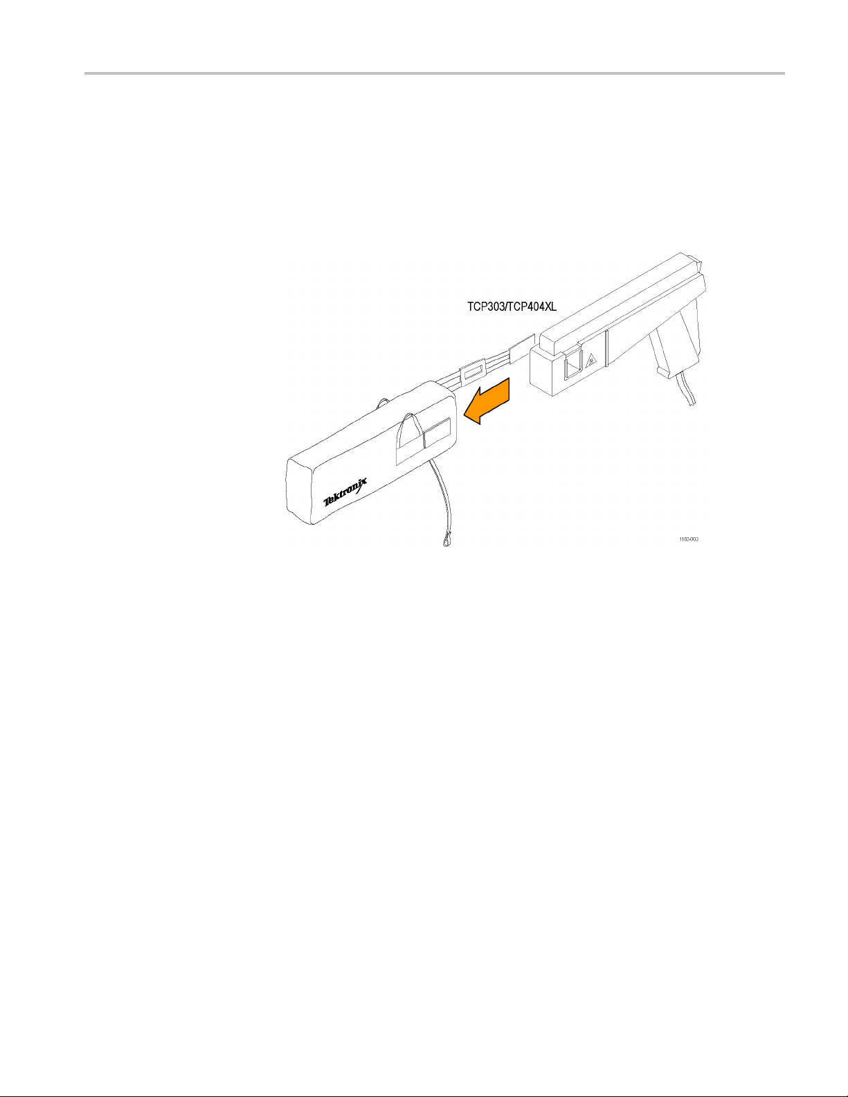
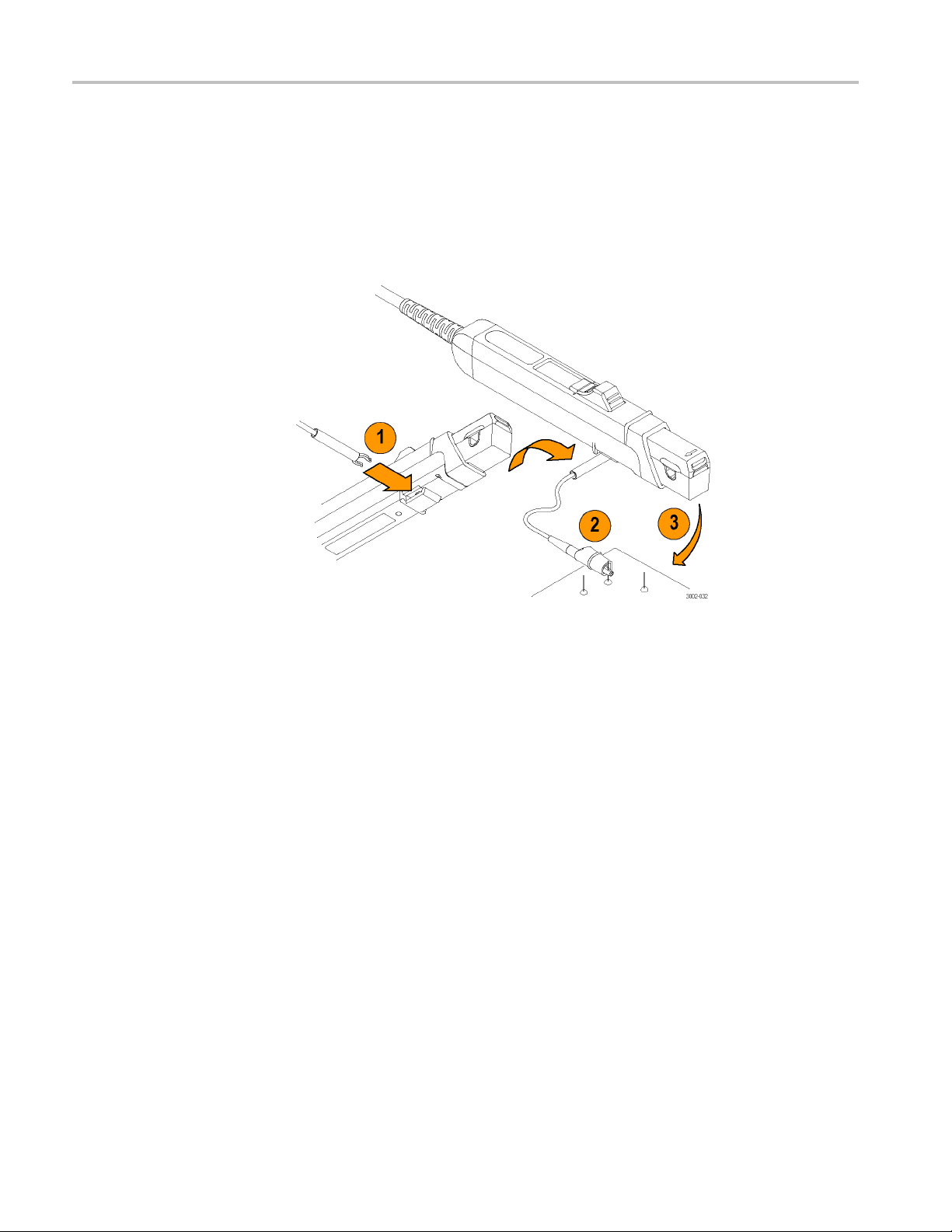
Connecting a C
urrent Probe to the Amplifier
To connect a current probe to the amplifier input connector, do the following and
refer to the illustration. (See Figure 5.)
1. To connect the probe, align the red dots.
2. Push the probe connector in. Do not twist the connector.
3. To disconnect the probe, pull back the collar.
4. Pull out the connector.
Figure 5: Connecting and disconnecting a current probe to the amplifier
CAUTION. Handle current probes with care. Do not drop a probe or subject it to
ct, or the core may crack.
impa
Do not connect or disconnect a current probe while the probe is clamped around a
ve conductor, or the probe may suffer electrical damage.
li
If you connect a probe to the wrong amplifier, (for example, a TCP312A to a
PA400), the NONCOMPATIBLE PROBE TYPE LED illuminates. Disconnect
TC
the probe and use the correct amplifier. The TCPA400 amplifier accepts
TCP3XXA probes, but will only operate properly with TCP4XX probes.
Each current probe is calibrated before it is shipped, and should not require
further adjustment. If a probe requires adjustment, information is available in the
service manual. The adjustment procedure must be performed only by qualified
service personnel. Contact your nearest Tektronix Service Center if you need
more assistance.
TCPA300/400 Amplifiers and TCP300A/400 Series Current Probes User Manual 9
Page 28
Getting Started
Operating the
Current Probe Slide
The current probes each ha ve a slide mechanism that opens and closes the probe
jaw. This allows you to clamp the probe around a conductor under test. The slide
must be locke
probe is unlocked, the PROBE OPEN indicator on the amplifier will light.
The current
the circuit must be de-energized when connecting or removing the current probe.
The slide o
the following illustration. (See Figure 6.) To open the probe, pull the slide back
until the jaw is open. To lock the probe, push the slide forward until the detent
snaps into place.
d closed to accurately measure current or to degauss the probe. If a
probes can be used to measure current on uninsulated wires. However,
peration of the TCP305A and TCP312A current probes is shown in
Figure 6: TCP312A and TCP305A s lide operation
10 TCPA300/400 Amplifiers and TCP300A/400 Series Current Probes User Manual
Page 29

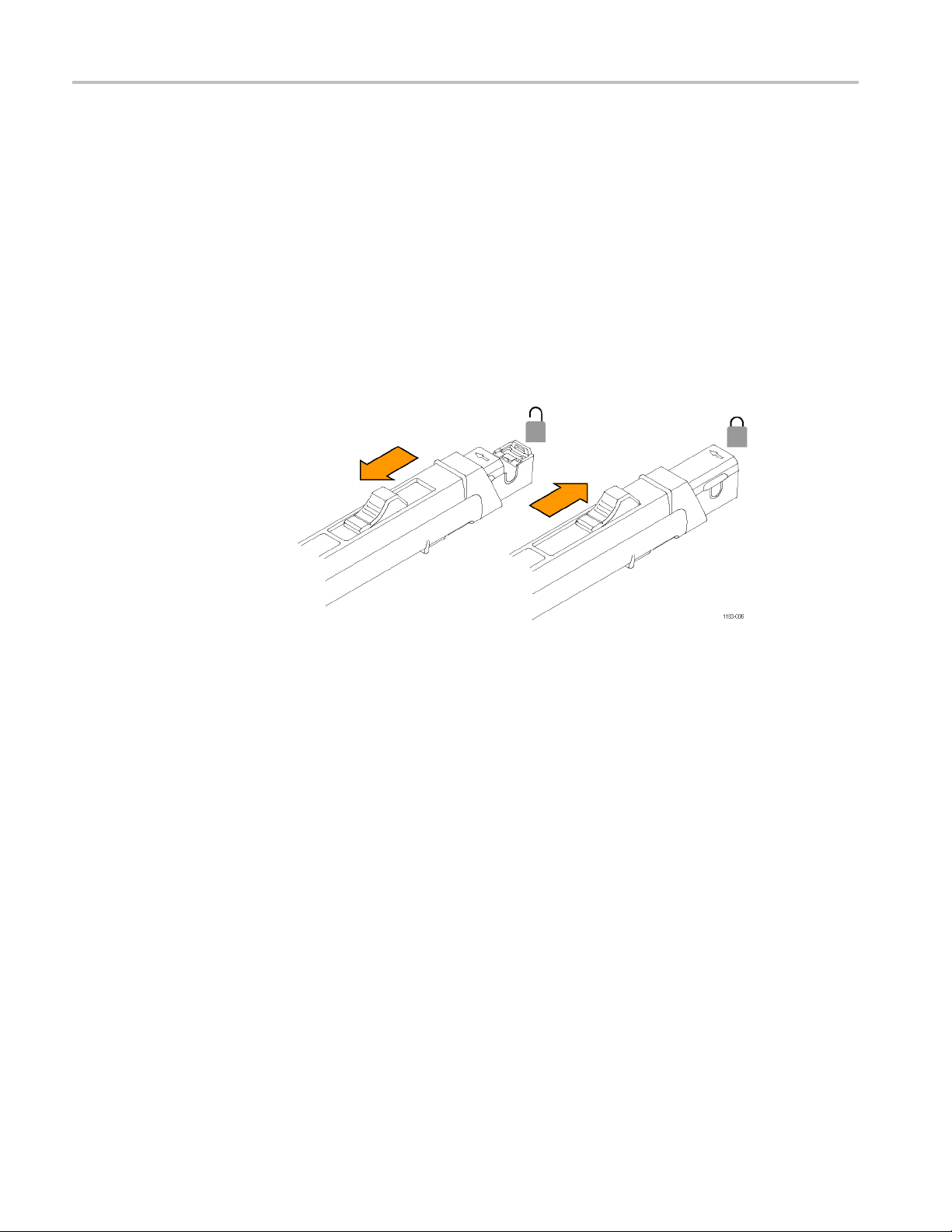
Getting Started
The slide opera
following illustrations. To open the probe:
1. Press the bott
2. Squeeze the handle until the core is open.
3. Place the probe core around the conductor.
tion of the TCP303 and TCP404XL current probes is shown in the
om of the lock button.
Figure 7: Unlock and open the TCP303 and TCP404XL
4. To lock the probe, release the squeeze handle.
5. Press the top of the lock button.
Figure 8: Close and lock the TCP303 and TCP404XL
TCPA300/400 Amplifiers and TCP300A/400 Series Current Probes User Manual 11
Page 30

Getting Started
Degaussing an
d Autobalancing the Current Probe
Degaussing the probe removes any residual magnetization from the probe core.
Such residual magnetization can induce measurement error. Autobalancing
removes unwa
probe is a leading cause of measurement errors. The DEGAUSS LED flashes
until you degauss the probe.
To degauss the probe, disconnect the probe from the test circuit, or ensure that
the conductor under test has no power, close and lock the slide, and then press
the amplifier PROBE DEGAUSS AUTOBALANCE button on the front panel of
the amplifier. To maintain measurement accuracy, degauss your probe in each of
these cases:
After you turn on the amplifier and allow a 20-minute warm-up period.
Before you connect the probe to a conductor.
Whenever a current or thermal overload condition occurs.
Whenever you connect a new probe.
Whene
Periodically during normal use.
To degauss and autobalance a current probe, perform these steps:
nted DC offsets in the amplifier circuitry. Failure to degauss the
ver you subject the probe to a strong external magnetic field.
1. Verify that the current probe is connected to the amplifier.
2. Remove the current probe from the conductor under test.
3. Lock the probe slide closed. (See Figure 6.) (See Figure 7.)
ess the amplifier PROBE DEGAUSS AUTOBALANCE button.
4. Pr
5. Wait about five seconds for the degauss procedure to complete.
The PROBE DEGAUSS AUTOBALANCE LED glows green when the
operation has successfully completed. If the LED is blinking orange, the degauss
peration is still in progress. If the LED is red, the operation failed, and the cause
o
of the failure needs to be found and fixed. (See page 18, PROBE DEGAUSS
AUTOBALANCE Button and Indicator.)
NOTE. The degauss procedure will fail if the amplifier is not properly connected
to an oscilloscope having 50 Ω input impedance. If this occurs, the NOT
TERMINATED INTO 50 Ω LED lights on the amplifier front panel.
After you have completed the oscilloscope adjustments and the amplifier
degauss/autobalance procedure, your system is ready to measure current.
12 TCPA300/400 Amplifiers and TCP300A/400 Series Current Probes User Manual
Page 31

Getting Started
DC Measuremen
ts
To measure DC current, first degauss the probe:
1. Verify that the a mplifi er and the oscilloscope input coupling are set to DC,
and the input impedance is set to 50 Ω.
2. Lock the probe closed without a conductor passing through it.
3. Adjust the ground reference of the oscilloscope to move the trace to the
desired graticule line.
4. Press the amplifier PROBE DEGAUSS AUTOBALANCE button.
The NOT TERMINATED INTO 50 Ω LED is lighted if impedance is not
50 Ω. If this is the case, make necessary changes. (For example, use a 50 Ω
termination.)
5. After the degauss/autobalance routine completes, adjust the ground reference
(if necessary) using the amplifier MANUAL BALANCE controls.
WAR N I NG. The current probes can be u sed to measure current on uninsulated
wires. However, the circuit must be de-energized when connecting or removing
rrent probe.
the cu
TCPA300/400 Amplifiers and TCP300A/400 Series Current Probes User Manual 13
Page 32

Getting Started
The current pro
Notice that the probe arrow points toward the negative terminal of the power
supplytoconf
To measure DC current, perform these steps:
1. Open the pro
then lock the slide.
2. For correct
the direction of conventional (positive to negative) current flow. Reversing
the flow will display the current waveform upside-down on the oscilloscope.
3. Adjust the oscilloscope time base, trigger, and gain as needed.
be is shown connected to a power supply line. (See Figure 9.)
orm to the conventional current flow of positive (+) to negative (-).
be slide, place the probe around the conductor under test, and
measurement polarity, make sure the probe arrow is pointing in
Figure 9: Arrow on current probe indicates conventional current flow
14 TCPA300/400 Amplifiers and TCP300A/400 Series Current Probes User Manual
Page 33

Getting Started
AC Measuremen
ts
To measure AC current only, and remove the DC component of the current being
measured, follow the instructions below. These are identical to the instructions for
DC current me
1. Verify that the oscilloscope input coupling is set to DC, and the input
impedance i
amplifier is lit if impedance is not 50 Ω.)
2. Verify tha
3. Adjust the ground reference of the oscilloscope to move the trace to the
desired g
4. Lock the probe closed without a conductor passing through it, and then press
the ampl
WAR N I NG. The current probes can be u sed to measure current on uninsulated
wires. However, the circuit must be de-energized when connecting or removing
the current probe.
5. Open the probe slide, place the probe around the conductor under test, and
then lock the slide. For correct measurement polarity, make sure the probe
arrow is pointing in the direction of conventional (positive to negative)
current flow. Reversing the flow will invert the displayed current waveform
on the oscilloscope.
asurements except that the amplifiercouplinginstep2issettoAC.
ssetto50Ω. (The NOT TERMINATED INTO 50 Ω LED on the
t the amplifier input coupling is AC.
raticule line.
ifier PROBE DEGAUSS AUTOBALANCE button.
E. Even when making AC current measurements, leave the oscilloscope
NOT
coupling on DC. Change only the amplifier coupling to AC. Using the oscilloscope
AC coupling may cause the amplifier to exceed its output dynamic range.
6. Adjust the oscilloscope time base and trigger as needed.
TCPA300/400 Amplifiers and TCP300A/400 Series Current Probes User Manual 15
Page 34

Getting Started
16 TCPA300/400 Amplifiers and TCP300A/400 Series Current Probes User Manual
Page 35

Control Summary
This section describes the function of each TCPA300 and TCPA400 front panel
control and connector. The overview shows most functions and is followed by a
detailed des
Some seldom-used functions do not appear in the illustration. These functions are
completely
cription. (See Figure 10.)
discussed in the detailed d escriptions that follow this illustration.
Figure 10: The TCPA300 front panel
1. The PROBE DEGAUSS AUTOBALANCE button removes residual
magnetism from the attached current probe. A m ulti-color LED indicates the
status of the degauss circuit.
2. The MANUAL BALANCE buttons allow you to fine-adjust DC offset from
the amplifier. The adjacent LED lights when one of the buttons has been
pressed.
3. The four probe error lights indicate the following faults: PROBE OPEN,
OVERLOAD (current or temperature), N OT TERMINATED INTO 50 Ω and
NONCOMPATIBLE PROBE TYPE.
4. The ON/STANDBY button turns on power to the amplifier.
5. The TCPA300 and TCPA400 output appears at the OUTPUT connector.
Connect this to a 50 Ω input of your oscilloscope.
TCPA300/400 Amplifiers and TCP300A/400 Series Current Probes User Manual 17
Page 36

Control Summary
6. The current pro
INPUT connector.
7. The COUPLING b
the LEDs.
8. The RANGE bu
for the attached probe (TCPA300 only). LEDs indicate the selected range.
TCPA300 and TCPA400 Controls
These front panel controls and indicators are common to both the TCPA300 and
TCPA400 current probe amplifiers, unless otherwise indicated.
PROBE DEGAUSS
AUTOBALANCE Button
and Indicator
When pres
accuracy. First, the amplifier generates a degauss signal to remove any residual
magnetism from the attached current probe. Second, the amplifier initiates an
operation to remove any undesired DC offsets from the circuitry. During the
degauss p rocess, the amplifier is busy and cannot be used to measure current.
The indicator light next to the PROBE DEGAUSS AUTOBALANCE button
blinks red whenever the amplifier detects that the current probe needs degaussing.
The amplifier cannot detect all circumstances that require probe degaussing,
so yo
AUTOBALANCE light is not blinking red. The red blinking light serves as a
reminder to degauss the current probe when one o f the following conditions
occurs:
sed, this button performs two functions that maximize measurement
u may need to degauss the probe at times when the PROBE DEGAUSS
bes connect to the TCPA300 and TCPA400 at the PROBE
utton selects AC or DC probe coupling, as indicated by
tton toggles between the two scale factors that are available
The amplifier has just been turned on with a current probe connected.
The current probe has been changed.
overload was detected.
An
To perform the probe degauss/autobalance function, remove the probe from
ll conductors (or ensure that the conductor under test has no power), make
a
sure the probe is locked closed, and then press the PROBE DEGAUSS
AUTOBALANCE button. The probe degauss/autobalance routine will not pass
if the current probe is disconnected from the amplifier input, or if it is unlocked
(the PROBE OPEN LED is on).
The indicator blinks orange during the time the amplifier is busy performing
the probe degauss functions. When the degauss and autobalance procedure is
complete, the indicator light turns green.
18 TCPA300/400 Amplifiers and TCP300A/400 Series Current Probes User Manual
Page 37

Control Summary
The PROBE DEGAU
the MANUAL BALANCE buttons have been pressed after a degauss has been
successfully completed. This indicates that the DC offset value has been manually
changed from the original value set during the degauss routine. Depending on
the amount of offset (balance) you have entered with the MANUAL BALANCE
buttons, another degauss operation may be necessary to ensure accurate
measuremen
you should de-energize the circuit under test and perform another degauss routine.
Then, reenergize the circuit and take your meas ure ments.
If the degauss operation has failed, and the AC and DC COUPLING LEDs are
alternately flashing, this indicates the amplifier is displaying an error code with
the four status LEDs on the lower-left front panel.
(See page 45, Displaying Error Codes with the Probe Degauss Autobalance
Button.)
NOTE. The NOT TERMINATED INTO 50 Ω LED is on when the amplifier
output is not properly terminated into a 50 Ω load. Makesureyouramplifier
OUTPU
that the oscilloscope input is set to 50 Ω impedance. Proper cabling is shown.
(SeeFigure1onpage1.)
ts. Generally, if you change the DC offset by more than 5 divisions,
T is connected to an oscilloscope input using a 50 Ω BNC cable, and
SS AUTOBALANCE indicator light will be orange if
MANUAL BALANCE
Buttons a nd Indicator
PROBE OPEN Indicator
OVERLOAD Indicator
If your oscilloscope does n ot have 50 Ω impedance settings for inputs, you can
place a 50 Ω feed-through termination on the oscilloscope input and connect
the amplifier output cable to the termination. Do not place the feed-through
termination at the amplifier end of the BNC connecting cable.
The MANUAL BALANCE buttons allow you to fine-adjust the DC offset that
appears at the amplifier OUTPUT connector. The manual balance adjustment
only functions when the amplifier is set to DC coupling, and the MANUAL
ALANCE indicator is only lighted after you press one of the MANUAL
B
BALANCE buttons in DC coupling mode.
When lit, this indicator informs you that the current probe is unlocked. You must
have the probe slide locked to degauss the p robe or to accurately measure current.
When this LED is red, it informs you that the measurement you are taking exceeds
the continuous current limit of the probe or amplifier.
When this LED is orange, it indicates that the safe operating temperature of the
probe, and possibly the amplifier, has been exceeded. Disconnect the probe from
the current source and allow time for the probe head and amplifier to cool.
TCPA300/400 Amplifiers and TCP300A/400 Series Current Probes User Manual 19
Page 38

Control Summary
NOT TERMINATED
NONCOM
PATIBLE
When this LED bl
temperature of the probe and the current limit have been exceeded.
WARNING. To avoid personal injury or equipment damage, do not exceed the
specified electrical limits of the TCPA300 and TCPA400 or any applicable
accessories.
When lit, th
cable from the OUTPUT of the amplifier is not connected to a 50 Ω input on the
oscilloscope. You need to switch the termination setting on the oscilloscope to
50 Ω,orusea50Ω termination on the oscilloscope input.
NOTE. NOT TERMINATED INTO 50 Ω is only detected during the DEGAUSS
AUTOBALANCE operation.
When lit, this indicator informs you that the probe that is connected to the
amplifier is not designed to work with the amplifier. TCP3XXA probes only
work with the TCPA300 Amplifier, and the TCP404XL probe only works with
the TC
PA400 Amplifier.
inks red and orange, it indicates that both the safe operating
is indicator informs you that the TEKPROBE interface cable or BNC
ON/STANDBY Button
RANGE Button
COUPLING Button and
Indicators
Use this button to power on the amplifier. When the amplifier is in STANDBY
mode, the amplifier is in a limited-power mode. Most of the secondary circuitry is
abled, but the line voltage remains connected to the amplifier power supply.
dis
Press the RANGE button to toggle between the scale factors (sensitivity settings)
of the probe attached to the TCPA300. If no RANGE LEDs are lit, this indicates a
obe is not connected to the amplifier.
pr
The COUPLING button determines the coupling between the TCPA300/TCPA400
and the oscilloscope. Press the COUPLING button to toggle between AC and
C coupling. To couple the amplifierforDCplusACmeasurements,useDC
D
coupling. For AC measurements only, use AC coupling. When the amplifier is set
to AC coupling, the Manual Balance adjustment is disabled since the DC offset
component is not visible on the output waveform.
NOTE. Even when making AC current measurements, leave the oscilloscope
coupling on DC. Change only the amplifier coupling to AC. Using the oscilloscope
AC coupling may cause the amplifier to exceed its output dynamic range.
20 TCPA300/400 Amplifiers and TCP300A/400 Series Current Probes User Manual
Page 39

Control Summary
PROBE INPUT Connector
OUTPUT Co
nnector
Under normal op
mode of the amplifier. If they alternately flash after a degauss operation, this
indicates the amplifier is displaying an error code with the four status LEDs on
the lower-left front panel. (See page 45, Displaying Error Codes with the Probe
Degauss Autobalance Button.)
All current probes compatible with the TCPA300 and TCPA400 attach at the
PROBE INPUT connector, which is a multi-pin female connector. Information
about connecting a probe is available. (See page 9, Connecting a Current Probe
to the A mplifier.)
The amplifier current measurement output is accessed at the OUTPUT connector,
which s hould be connected to the oscilloscope input. Attach one end of a 50 Ω
BNC cable to this connector and the other end to a 50 Ω vertical input of your
scope. The output impedance of the amplifier is 50 Ω.
oscillo
To get a direct readout of current on your Tektronix oscilloscope, use the
TEKPRO
NOTE. To obtain accurate measurements, the input impedance of your
oscilloscope must be 50 Ω. Make sure your amplifier OUTPUT is connected to an
oscilloscope input using a 50 Ω BNC cable, and that the oscilloscope input is set
to 50 Ω impedance. The proper cabling is shown. (See Figure 1 on page 1.)
BE interface cable to connect the amplifier to your oscilloscope.
eration, the AC and DC COUPLING LEDs indicate the coupling
Probe DC Gain Adjust
ocated on probes)
(l
If your oscilloscope does not have 50 Ω impedance settings for inputs, you can
place a 50 Ω feedthrough termination on the oscilloscope input and connect
the amplifier output cable to the termination. Do not place the feedthrough
mination at the amplifier end of the BNC connecting cable.
ter
After the PROBE DEGAUSS AUTOBALANCE routine has been run, the probe
nd amplifier system will meet all published specifications. However, if you want
a
to improve the tolerance of the system accuracy, or to intentionally offset the
accuracy to make up for total system errors, you can manually adjust the gain of
the probe. See the service manual for adjustment procedures and locations.
NOTE. You should be careful to note the existing position of the DC Gain
Adjustment before you alter it, so that you may return it to the initial, calibrated
position. By altering the DC Gain Adjustment, you may cause the probe to not
meet the warranted DC Accuracy specification.
TCPA300/400 Amplifiers and TCP300A/400 Series Current Probes User Manual 21
Page 40

Control Summary
GPIB Operation
For example, th
1%. If you want to measure a 3 Ap-p, 1 kHz square wave and need increased
accuracy (better than 0.25% is attainable), first adjust the TCP312A on the 1 A/V
range setting using a calibrated 3 Ap-p, 1 kHz square wave source. Then, attach
the probe to your circuit and take your measurement. Remember, altering the DC
Gain Adjustment may cause the probe to not meet the warranted DC Accuracy
specificati
The TCPA300 and TCPA400 Current Probe Amplifiers do not have direct GPIB
connections. However, you can use a computer to control the oscilloscope that the
amplifier
your current measurements over the oscilloscope GPIB bus.
Refer to
your oscilloscope manual for instructions on using the GPIB bus.
e typical accuracy of the TCP312A probe on the 1 A/V range is
on.
is connected to, enabling you to change the time and scale factors of
22 TCPA300/400 Amplifiers and TCP300A/400 Series Current Probes User Manual
Page 41

Reference Notes
These notes are provided to help you utilize the full potential o f the TCPA300
and TCPA400 current probe systems.
Degaussing a Probe with an Unpowered Conductor in the Jaws
Under almost all conditions, you can degauss your current probe while a conductor
of an unpow
with an unpowered circuit is that any offset from stray DC magnetic fields are
compensated. In an automated environment, degaussing with the conductor in the
probe jaws eliminates the need to manually remove the probe.
NOTE. Be certain that the conductor in the probe jaws is completely unpowered.
Any current flowing through the conductor will cause a residual offset in the
current
If the impedance of your circuit is higher than that shown, the degauss procedure
eds because the amplifier is able to saturate the probe core. (See Figure 12
succe
on page 25.) While degauss occurs, the probe induces a voltage in the unpowered
circuit as shown. (See Figure 12 on page 25.) Your circuit must be able to absorb
this induced voltage. With low impedance circuits, several amperes may be
induced in the circuit being measured. This may be of concern when you are
using very small conductors.
ered circuit is clamped in the jaws. The advantage of degaussing
probe, and the amplifier may report an inaccurate result.
le 4: Unpowered circuit degauss limits
Tab
imum circuit
Min
Probe type
TCP312A 10 mΩ
TCP305A 5 mΩ
TCP303 5 mΩ
TCP404XL 1 mΩ
resistance Maximum induced voltage
mV at 200 Hz
40
mV at 200 Hz
40
0 mV at 200 Hz
3
5 mV at 100 Hz
1
TCPA300/400 Amplifiers and TCP300A/400 Series Current Probes User Manual 23
Page 42

Reference Notes
Measuring Dif
ferential Current
You can place two conductors in a current probe to provide differential or null
current measurement. (See Figure 11.) This avoids the necessity of using two
current meas
Figure 1
WARNING. To avoid injury or loss of life from shock or fire, do not put more than
one uninsulated conductor at a time in the probes.
1: Measuring two conductors
urement systems with a differential oscilloscope.
An insulated conductor is defined as any conductor that is surrounded by an
insulating material that is capable of isolating the voltage present on the conductor.
Note that lacquer coatings like those typically found on transformer windings do
not provide sufficient, reliable insulation for use with current probes. The lacquer
coating can be easily nicked or damaged, compromising the insulating capabilities
e lacquer coating.
of th
Do not force the slide closed. Damage to the probe may result. If you cannot close
slide around the conductor(s), either reduce the number of conductors you are
the
measuring, or, if possible, take your measurement on a smaller conductor.
ient the two conductors under test so that the polarities oppose each other.
1. Or
2. Clamp the current probe around the two conductors as shown. Be careful not
o pinch a conductor in the probe jaws.
t
24 TCPA300/400 Amplifiers and TCP300A/400 Series Current Probes User Manual
Page 43

Reference Notes
Figure 12: Measuring differential current and nulls
3. Measure the current. A waveform above the baseline indicates the conductor
with the conventional current flow (I
, in the direction of the probe arrow),
1
is carrying the greater current. Conventional current flows from positive to
negative.
4. To adjust for a current null, adjust the current in one of the conductors until
the displayed measurement is zero.
TCPA300/400 Amplifiers and TCP300A/400 Series Current Probes User Manual 25
Page 44
Reference Notes
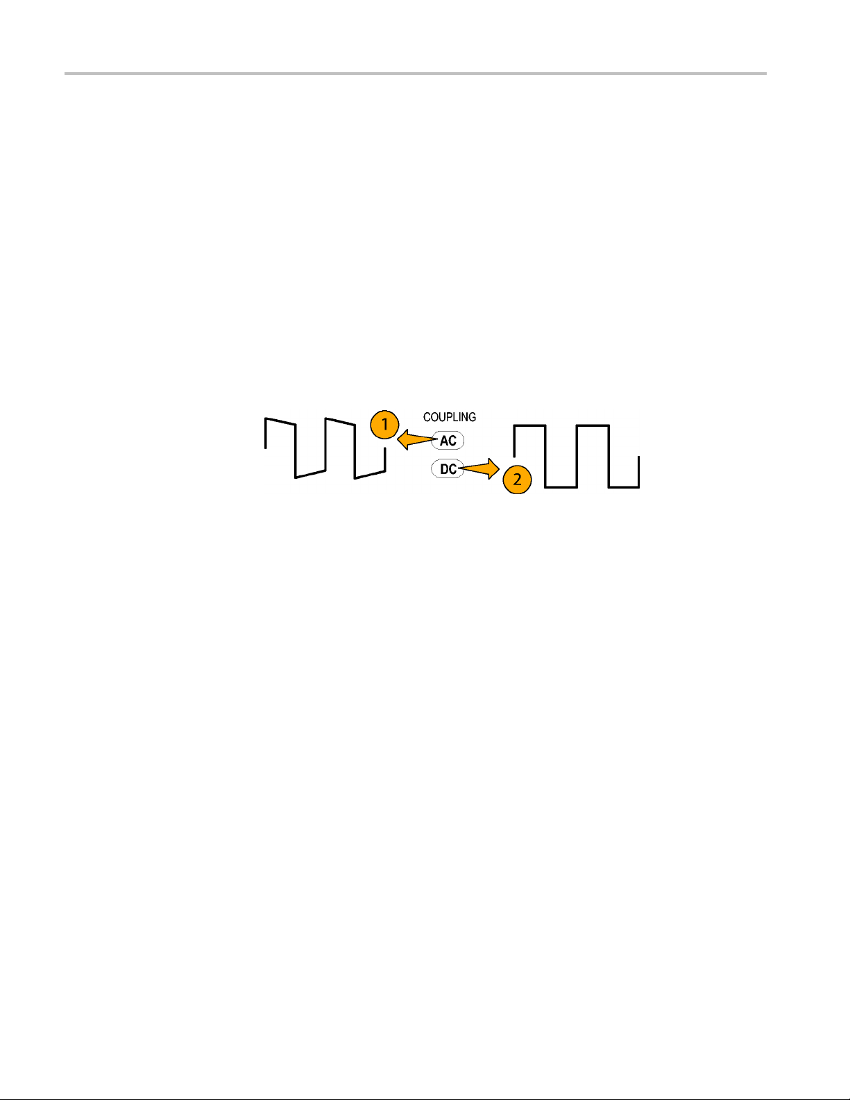
AC and DC Coupl
ing
You can couple the signal input to the TCPA300 and TCPA400 with either DC
or AC coupling. DC coupling shows the DC and AC measurement components
while AC coup
you use AC coupling, make sure that the input DC current does not exceed the
probe specifications.
AC coupling will affect waveforms at frequencies higher than the AC Coupling
Low-Frequency Bandwidth. For example, pulsed currents may exhibit rolloff or
decreased amplitude. (See Figure 13.)
1. A low-frequency square wave using AC coupling. The signal exhibits
low-frequency rolloff.
2. By changing the amplifier coupling to DC, the pulse is displayed as truly
square, as shown.
e 13: Effect of AC or DC coupling on low-frequency signals
Figur
ling removes the DC component from the displayed signal. When
u are trying to examine a low-frequency signal that is superimposed on a
If yo
comparatively large DC component, you can resolve the signal by p erforming
these steps:
1. Select the range setting that will display the maximum detail without
exceeding the dynamic range of the signal.
2. Adjust the oscilloscope V/div sensitivity (A/div if using the TEKPROBE
interface), to display maximum signal detail.
26 TCPA300/400 Amplifiers and TCP300A/400 Series Current Probes User Manual
Page 45
Reference Notes
Maximum Curre
nt Limits
Current probes have three maximum current ratings: continuous, pulsed, and
Ampere-second p roduct. Exceeding any of these ratings can saturate the probe
core, magnet
NOTE. Always degauss the probe after measuring a current that exceeds the
maximum continuous current, maximum pulsed current, or Ampere-second
product rating of the probe. Exceeding these ratings can magnetize the probe
and cause measurement errors.
izing the core and causing measurement errors.
Maximum Continuous Current refers to the maximum current that can be
continuous
Specifications.) The maximum continuous current value is derated with
frequency; as the frequency increases, the maximum continuous current
rating decreases.
Maximum Pulsed Current refers to the maximum peak value of pulsed current
the probe can accurately measure, regardless of how short (within bandwidth
limitations) the pulse duration is.
Ampere-Second Product defines the maximum width of pulsed current
that you can measure when the pulse amplitude is between the maximum
continuous and maximum pulsed current specifications. The maximum
contin
ly measured at DC or at a specified AC frequency. (See page 49,
uous specification itself varies by frequency.
etermine if your measurement exceeds the Ampere-second product, perform
To d
either Procedure A (Maximum Allowable Pulse Width), or Procedure B
(Maximum Allowable Pulse Amplitude).
TCPA300/400 Amplifiers and TCP300A/400 Series Current Probes User Manual 27
Page 46

Reference Notes
Procedure A: Maximum
Allowable Pulse Width
To determine th
e maximum allowable pulse width do the following:
1. Measure the peak current of the pulse.
2. Divide the Ampere-second (or Ampere-microsecond) specification for the
range setting of the probe by the measured peak current of the pulse. The
quotient is
the maximum allowable pulse width (PW
max
).
For example, the TCP312A Current Probe has a maximum Ampere-second
product of 500 A-μs in the 10 A/V range setting. If a pulse measured with a
TCP312A has a peak current of 40 A, the maximum allowable pulse width
would be 500 A-μs divided by 40 A, or 12.5 μs.
3. Check that the pulse width at the 50% point of the measured signal is less than
the calculated m aximum allowable pulse width (PW
max
).
Figure 14: Applying the amp-second product rule
28 TCPA300/400 Amplifiers and TCP300A/400 Series Current Probes User Manual
Page 47

Reference Notes
Procedure B: Maximum
Allowable Pulse Amplitude
To determine th
1. Measure the pulse width at the 50% points.
2. Divide the Ampere-second (or Ampere-microsecond) specification for the
range setting of the probe by the pulse width. The quotient is the maximum
allowable p
be less than this value.
For example
product of 500 A-μs in the 10 A/V range setting. If a pulse measured with a
TCP312A probe has a width of 15 μs, the maximum allowable peak current
would be 500 A-μs divided by 15 μs, or 33.3 A.
e maximum allowable pulse amplitude do the following:
ulse amplitude; the peak amplitude of the measured pulse must
, the TCP312A Current Probe has a maximum Ampere-second
TCPA300/400 Amplifiers and TCP300A/400 Series Current Probes User Manual 29
Page 48

Reference Notes
Measuring Non
continuous Current with the TCP404XL Probe
When you measure a noncontinuous current with the TCP404XL probe, you
need to take into consideration several factors to ensure that you make accurate
measurement
and duty cycle of the continuous and noncontinuous current, and the ambient
temperature, all affect the maximum amount of time allowed for the measurement,
which defines the safe operating area of the probe.
You can calculate the duty cycle of the continuous and noncontinuous
current when you know the duration of the noncontinuous current (defined as
measurement time) and the measurement period. A continuous and noncontinuous
current is shown and how to calculate the duty cycle. (See Figure 15.)
s and do not trip the thermal overload circuit. The amplitude
ure 15: Duty cycle calculation
Fig
er you calculate the duty cycle of the noncontinuous current you are measuring,
Aft
you can use the other factors (continuous and noncontinuous current amplitude,
etc.) to compare your measurement to those shown. (See Figure 35 on page 58.)
(See Figure 37 on page 59.)
You can see how duty cycle affects the measurement time by looking at any of
thethreegraphs. (SeeFigure35onpage58.)(SeeFigure37onpage59.) Asthe
duty cycle increases on the x-axis, the measurement time (of the noncontinuous
current) on the y-axis decreases.
30 TCPA300/400 Amplifiers and TCP300A/400 Series Current Probes User Manual
Page 49
Reference Notes
The effect of me
and 600 A respectively, with varying duty cycles and levels of continuous current
is illustrated. (See Figure 35 on page 58.) (See Figure 36 on page 58.) The
ambient temperature in these two examples is kept constant at 50 °C.
WAR N I NG. To prevent injury, keep your hands away from the probe head until it
has had time to cool after disconnecting the probe from the circuit. Because when
using the pr
for extended lengths of time, the probe head surface can become hot to the touch.
To see how
the curves for measurements of 200 A continuous between the two graphs. (See
Figure 35 on page 58.) (See Figure 36 on page 58.) Compare the maximum
measurement time allowed for a duty cycle of 20%: At 750 A, you have 3 minutes
of safe measurement time, versus 17 minutes for a smaller noncontinuous-current
amplitude of 600 A.
By looking at any of the three graphs, you can also see that when you measure
a noncontinuous current having the same amplitude and duty cycle, the
rement time decreases as the continuous-current amplitude increases.
measu
Finally, compare the two graphs. (See Figure 35 on page 58.) (See Figure 37
ge 59.) Here, the effect of ambient temperature on measurement time is
on pa
illustrated. Given a continuous current of 200 A with a noncontinuous current
of 750 A, and having a 20% duty cycle, a 27 °C increase in temperature yields a
12 minute decrease in maximum measurement time.
asuring two different noncontinuous current amplitudes, 750 A
obe near the upper current limit and maximum ambient temperature
noncontinuous current amplitude affects measurement time, look at
Keep these factors into account when taking measurements to ensure accuracy
and to protect both yourself from injury and the equipment from damage.
TCPA300/400 Amplifiers and TCP300A/400 Series Current Probes User Manual 31
Page 50

Reference Notes
Extending Cur
Extending DC Range
rent Range
You may encounter situations where your measurement exceeds the maximum
current rating of the connected probe. This section discusses methods for
extending AC
WARNING. To avoid personal injury or loss of life due to shock or fire, do
not exceed the specified electrical limits of the TCPA300 and TCPA400 or any
applicable accessories. When using multiple conductors, do not exceed current
limits on either conductor.
If you wan
an extremely large steady-state DC component (such as in a power supply), or
if you want to extend the DC current range of your probe, you can add offset
(bucking) current with a second conductor.
WARNING. To avoid injury or loss of life from shock or fire, do not put more than
one uninsulated conductor at a time in the probe jaws. An uninsulated conductor
is defi
voltage present on the conductor under test.
and DC current ranges without exceeding specified limits.
t to measure a low-amplitude AC component that is superimposed on
ned as any conductor without insulation or without insulation rated for the
pply additional bucking current, do the following and refer to the illustration.
To su
(See Figure 16.)
1. Pla
2. Or
3.T
ce a second conductor that has a pure DC component of known value in
the probe jaw with the conductor under test.
ient the second conductor so that the bucking current flows in the opposite
direction of the DC flow in the c onductor under test.
o determine measurement values, add the value of the bucking current to
the displayed measurement.
32 TCPA300/400 Amplifiers and TCP300A/400 Series Current Probes User Manual
Page 51

Reference Notes
Figure 16: Adding a second conductor
NOTE. Adding a second conductor to the probe increases the insertion impedance
and reduces the upper bandwidth limit of the probe.
You can increase the value of the bucking current by winding multiple turns of the
second conductor around the probe, as shown in the illustration. (See Figure 17.)
Figure 17: Adding multiple turns
The bucking current is equal to the current flowing in the conductor, multiplied
by the number of turns wound around the probe. For example, if the second
conductor has a current of 100 mA DC and is wrapped around the probe five
times, the DC bucking current is 100 mA multiplied by 5, or 500 mA DC.
To determine measurement values, add the value of the bucking current to the
displayed measurement.
NOTE. Winding multiple turns to the probe increases the insertion i mpedance and
reduces the upper bandwidth limit of the probe.
TCPA300/400 Amplifiers and TCP300A/400 Series Current Probes User Manual 33
Page 52

Reference Notes
Increasing Se
nsitivity
If you are measuring DC or low-frequency AC signals of very small amplitudes,
you can increase measurement sensitivity of your Current Probe by winding
several turn
multiplied by the number of turns around the probe.
WARNING. To avoid injury or loss of life, do not put more than one uninsulated
conductor at a time in the probe jaws. An uninsulated conductor is defined as any
conductor without insulation or without insulation rated for the voltage present
on the conductor under test.
When viewing the signal on the oscilloscope screen, divide the displayed
amplitude by the number of turns to obtain the actual current value. For example,
if a conductor is wrapped around the probe five times and the oscilloscope shows
a reading of 5 mA DC, the actual current flow is 5 mA divided by 5, or 1 mA DC.
NOTE. Winding multiple turns around the probe increases insertion impedance
and re
s of the conductor under test around the probe as shown. The signal is
duces the upper bandwidth limit of the probe.
Figure 18: Increasing probe sensitivity
34 TCPA300/400 Amplifiers and TCP300A/400 Series Current Probes User Manual
Page 53

Application Notes
This section describes some of the typical measurement applications of the
TCPA300 and TCPA400 Current Probe Amplifiers:
Application Notes
Automobile Charging Systems
Inductance Measurements
Continuity Test of Multiple-Conductor Cable
Measuring Inductor Turns Count
Power Mea
Automobile Charging Systems
Most aut
rectifier network. A meter averages current from all three phases, and cannot
detect a single-phase diode problem. Observing the charge current waveform can
quickly reveal if one diode is shorted or open. (See Figure 20 on page 36.)
A TCP303 Current Probe was used for this high-current, low-voltage application.
The TCP303 is degaussed and clamped around the positive battery lead from the
alternator. (See Figure 19.) The probe arrow is pointed away from the alternator
and toward the battery side of the circuit, to reflect conventional curre nt. The
auto
circuit.
Table 5: Automobile charging systems test setup
Instrument Control Setting
TCPA300 COUPLING DC
Oscilloscope Coupling DC
omotive charging systems are three-phase alternators with a diode
mobile is started and the lights are turned on to add a significant load to the
surement and Analysis Software Applications
RANGE 50 A/V
Amps/Division
(Volts/Division if not using
TEKPROBE interface cable)
Zero-Current Reference Center graticule line
Time Base
10 A/Div (200 mV/Div)
200 ms/division
TCPA300/400 Amplifiers and TCP300A/400 Series Current Probes User Manual 35
Page 54

Application Notes
Figure 19: Setup for measuring charging current
The waveform (a) shows the three-phase ripple frequency. (See Figure 20.)
The average charge current is approximately 27 A with a minimum peak of
approximately 23 A and a maximum peak of approximately 31 A. The waveform
shows a continuous cycle w ith no dropouts, so the alternator circuit appears to be
ioning properly. A single-phase diode failure normally appears as an extreme
funct
drop in charge current every third cycle, waveform (b). (See Figure 20.)
gure 20: Charge current waveforms
Fi
36 TCPA300/400 Amplifiers and TCP300A/400 Series Current Probes User Manual
Page 55

Inductance Measurements
You can use the TCPA300 and TCPA400 to measure inductance of coils. Two
different methods can be used: one for low-impedance pulse sources and another
for high-impedance pulse sources o f known value.
Application Notes
Low-Impedance Pulse
Sources
This figure shows a constant-voltage pulse generator of extremely low output
impedance connected to an inductor that has low resistance. (See Figure 21.)
1. Connect the inductor across the output terminals of the pulse generator.
2. Maintain a constant voltage across the inductor.
3. Clamp the
current probe over one of the source leads.
Figure 21: Measuring inductance with a low-impedance source
E. Iftheprobeimpedanceisasignificant part of the total circuit inductance,
NOT
measurement accuracy will be affected. Refer to the probe specifications for
probe insertion impedance.
TCPA300/400 Amplifiers and TCP300A/400 Series Current Probes User Manual 37
Page 56

Application Notes
4. Measure the cur
of the current ramp shown here.
Figure 22: Linear current vs. time ramp
5. Calculate the inductance using the following formula:
where:
L is the inductance in henries,
E is the voltage of the pulse generator,
dt is the change in time, and
di is the change in current.
rent ramp. The inductance is effectively defined by the slope
38 TCPA300/400 Amplifiers and TCP300A/400 Series Current Probes User Manual
Page 57

Application Notes
High-Impedance Pulse
Sources
If the pulse sou
output voltage drops as the current increases, the inductance of a coil can be
calculated by the time constant of the charge curve. The current ramp shows how
the values for the inductance formula are obtained. (See Figure 23 on page 39.)
Use this formula to calculate the inductance based on the current measurement:
where L is the inductance in henries, τ is the time required for the current to rise or
fall 63.2% of the total current value, and R is the source resistance of the pulse
generator.
rce has a higher impedance of known resistance, such that the
Figure 23: High-impedance source current ramp
inuity Test of Multiple-Conductor Cable
Cont
Single conductors in a multiconductor cable can be tested with the TCPA300 and
TCPA400. To check a conductor, clamp the current probe around the cable bundle
d check for a specific, known current signal. If there is no current or the current
an
is abnormally low, then the conductor has a continuity problem. If the current is
abnormally high, then the conductor may have a short to ground.
TCPA300/400 Amplifiers and TCP300A/400 Series Current Probes User Manual 39
Page 58

Application Notes
Measuring Ind
uctor Turns Count
To obtain an approximate turns count of an inductor, do the following. (See
Figure 24.)
1. Connect the inductor to a current limited source, as shown.
2. Measure the input current on one of the inductor leads.
3. Clamp the current probe around the inductor and note the current value.
Figure 24: Measuring the number of turns in a coil
The number of turns is equal to the ratio of coil current to input current. The
accuracy of this method is limited by the current measurement accuracy. The
following method allows more precise turns measurement.
For a more precise turns count, you need a coil with a known number of turns
to use as a reference.
1. Repeat steps 1 a nd 2 above and make the following changes:
2. Insert the reference coil into the current probe.
3. Insert the test coil into the current probe so that the currents oppose each other
as shown. (See Figure 25.)
Figure 25: Turns measurement using reference coil
40 TCPA300/400 Amplifiers and TCP300A/400 Series Current Probes User Manual
Page 59

Application Notes
You must observ
has greater or fewer turns than the reference coil. The turns are calculated by
using the formula:
where N2is the number of turns in the test coil, N1is the number of turns in the
reference coil, I
e the polarity of coil current to determine whether the test coil
is the measured coil current, and I1is the input current.
m
Power Measurement and Analysis Software
Power measurement software that is available for some Tektronix oscilloscopes
transform your current measurement system into a sophisticated analysis tool that
quickly measures and analyzes many different applications, such as:
Power dissipation at switching devices and magnetic components in switching
power supplies
Precompliance test for EN61000-3-2 standard
Power quality
Modulation analysis
After making the measurements, the software generates detailed test reports in
customizable formats. When the software is used with a Tektronix TDS5000
Series or TDS7054/TDS7104 digital phosphor oscilloscope and differential
voltage and current probes, it forms a complete measurement system for power
supply design and test.
TCPA300/400 Amplifiers and TCP300A/400 Series Current Probes User Manual 41
Page 60

Troubleshooting and Error Codes
Troubleshoot
ing and Error Codes
Possible pro
blems that you may encounter when measuring current with the
TCPA300 and TCPA400 are available. (See Table 6.) Use this as a quick
troubleshooting reference.
Table 6: Troubleshooting
Problem Remedy
Amplifier will not power on Check that the amplifier is plugged into a working AC outlet.
Defective amplifier. Refer the instrument to qualified service personnel for repair. To
help determine which module is defective, a troubleshooting section is available in the
service manual.
Front panel displays an error status.
Error Status LEDs are on the lower-left
section of the amplifier front panel
The AC and DC COUPLING LEDs are
flashing alternately
All LEDs are flashing All LEDs flashing indicates a thermal shutdown. Power-cycle the system and let it cool
OVERLOAD LED remains lit red after
removing probe from circuit
OVERLOAD LED remains lit orange Degauss the probe. If the OVERLOA D LED remains lit orange, disconnect the probe
Probe does not degauss successfully
and LEDs are lighted in an unfamiliar
pattern
Cannot degauss the probe Current Probe is not locked. Lock the current probe.
Note the error status and correct the condition. The error status is labeled on the front
panel. For example, if the PROBE OPEN LED is lit, close and lock the probe jaws.
The Error Status LEDs are displaying an error code. Error codes descriptions are
available. (See Table 7 on page 46.) Note the error code and turn the instrument off, then
on. If the error condition persists, refer the instrument to qualified service personnel
for repair.
If the RANGE and DEGAUSS LED are both off, and one of the COUPLING LEDs is lit,
this indicates the amplifier is not detecting a probe. Reconnect the probe.
All LEDs flashing indicate a thermal shutdown. Power-cycle the system and let it cool for
15 minutes before taking measurements. In most cases, 15 minutes is sufficient.
before taking measurements. In most cases, 15 minutes is sufficient.
Probe transformer or amplifier main board is defective.
from the circuit and let it cool for 15 minutes before degaussing again. If this does not
clear the LED, the probe transformer or probe Hall device may be defective. Connect
another probe to the amplifier, or connect the probe in question to another amplifier.
Amplifier is displaying an error code or is out of calibration or defective. (See Table 7 on
page 46.) If another amplifier is available, try to degauss the probe on the other amplifier,
to help isolate the cause.
Component failure on probe circuit board: broken adjustment/wire/etc. Disassemble
probe, repair/replace component or refer the instrument to qualified service personnel
for repair.
Current Probe is improperly connected to the amplifier input connector.
Amplifier output is not terminated into 50 Ω load. Set input impedance of oscilloscope
to 50 Ω or connect a 50 Ω feed-through termination at the oscilloscope input, not at
the amplifier output.
Current Probe is defective or not compatible with the amplifier type.
42 TCPA300/400 Amplifiers and TCP300A/400 Series Current Probes User Manual
Page 61

Troubleshooting and Error Codes
Table 6: Troubleshooting (cont.)
Problem Remedy
Degauss takes longer than 10 seconds
Cannot make a current measurement no measurement output from amplifier
MANUAL BALANCE will not adjust Oscilloscope or amplifier input coupling not set to DC. MANUAL BALANCE buttons only
Stray DC component in measurement Degauss the probe using the PROBE DEGAUSS AUTOBALANCE button. (The Current
Measurements are inaccurate Degauss the probe.
Measurements roll off at high
frequencies
Measurements exhibit excessive noise
Probe is attached to an energized circuit. Disconnect probe from circuit and retry.
Probe is faulty - Probe transformer (defective Hall device with excessive noise or drift)
may cause this symptom. May also be caused by a shorted or open wire in the probe
cable assembly.
Defective main board - If the probe is not the cause, then it is most likely a defective
main board in the amplifier.
Current Probe is not locked. Lock the current probe.
Current Probe is improperly connected to the amplifier input connector.
Amplifier COUPLING is set to AC. Set the COUPLING to DC.
A Degauss/Autobalance routine has not been completed successfully on the system.
Degauss the probe.
Oscilloscope/Amplifier is not set to an appropriate sensitivity setting.
Defective interface cable (between oscilloscope and amplifier).
function when the ampli fier is in the DC coupling mode.
Oscilloscope/Amplifier is not set to an appropriate sensitivity setting.
Probe has been overloaded, dropped, or exposed to magnetic field.)
You can use the MANUAL BALANCE buttons to null out any residual DC offset after
performing a Probe Degauss Autobalance routine.
The amplifier output is not terminated into 50 Ω load. Set the input impedance of
oscilloscope to 50 Ω or connect a 50 Ω feedthrough termination at the oscilloscope input.
Do not attach the termination at the amplifier output.
The measurement exceeds the maximum continuous current or Ampere-second product
ratings of the Current Probe.
Amplifier or current probe out of calibration. (See the service manual for performance
verification procedures.)
Defective current probe transformer.
The oscilloscope bandwidth limit is turned on. Verify that the bandwidth limit switch on
the oscilloscope is set to the desired bandwidth position.
(Be careful not to exceed the frequency limit of the probe used. Frequencies above the
probe design may cause overheating and damage to the probe.)
Current Probe is not locked. Lock the current probe.
Current Probe is improperly connected to the amplifier input.
Amplifier output is not terminated into 50 Ω load. Set input impedance of oscilloscope
to 50 Ω or connect a 50 Ω feedthrough termination at the oscilloscope input, not at the
amplifier output.
Defective current probe transformer.
TCPA300/400 Amplifiers and TCP300A/400 Series Current Probes User Manual 43
Page 62

Troubleshooting and Error Codes
Table 6: Troubleshooting (cont.)
Problem Remedy
Measurement aberrations exceed the
specified limit
Excessive low frequency droop in pulse
response or low DC gain accuracy
Measurements exhibit excessive delay
or slowed pulse response
The amplifier output is not terminated into 50 Ω load. Set the input impedance of the
oscilloscope to 50 Ω or connect a 50 Ω feedthrough termination at the oscilloscope input.
Do not attach the termination to amplifier output.
The measurement exceeds the maximum continuous current or Ampere-second product
ratings of the Current Probe. (Current limits are available) (See page 27, Maximum
Current Limits.)
Check that the probe slider is fully closed and locked.
Check and clean the probe transformer and lid.
Degauss the probe.
The amplifier or the oscilloscope may be AC coupled. Set the COUPLING to DC.
The amplifier output is not terminated into 50 Ω load. Set the input impedance of the
oscilloscope to 50 Ω or connect a 50 Ω feedthrough termination at the oscilloscope input.
Do not attach the termination to the amplifier output.
The measurement exceeds the Ampere-second product of the Current Probe.
The oscilloscope bandwidth limit is turned on. Verify that the bandwidth limit switch on
the oscilloscope is set to the desired bandwidth position.
44 TCPA300/400 Amplifiers and TCP300A/400 Series Current Probes User Manual
Page 63

Troubleshooting and Error Codes
Displaying Er
ror Codes with the Probe Degauss Autobalance Button
This section describes the error codes that the amplifiers display using the
function indicator LEDs.
When an internal error condition exists, the amplifiers may generate error codes.
To display the error codes, do the following. (See Figure 26.)
1. Press the PROBE DEGAUSS AUTOBALANCE button.
2. The AC and DC Coupling LEDs will flash alternately to indicate that error
codes are being displayed instead of normal conditions.
3. The four fault indicator LEDs above the ON/STANDBY switch are used to
form a four-bit binary error code. (See Figure 27 on page 46.) The error codes
are defined in the table. (See Table 7 on page 46.)
The PROBE OPEN LED indicates the most significant bit (MSB), and the
NONCOMPATIBLE PROBE TYPE LED indicates the least significant bit
(LSB).
4. To continue past an error code, press any button except ON/STANDBY.
Howev
and the degauss operation is run again.
er, the degauss will fail until the internal error condition is corrected
Figure 26: Error code display
TCPA300/400 Amplifiers and TCP300A/400 Series Current Probes User Manual 45
Page 64

Troubleshooting and Error Codes
For example, af
ter you press the PROBE DEGAUSS AUTOBALANCE button, if
the AC and DC Coupling LEDs are flashing, then an error code is being displayed:
1. In this exampl
e, the NOT TERMINATED INTO 50 Ω LED is illuminated.
2. This four-bit binary code (0010) indicates an Error Code 2: a null error in the
DC offset ci
rcuit occurred. (See Figure 27.)
Figure 27: Interpreting the error code display
A complete list of error codes for the amplifier is listed in the table. (See Table 7.)
Table 7: Amplifier error codes
Code Descrip
1
2
3
4
5
6
7
8
9
The am p
a probe, but a valid Hall
device was not detected.
or occurred while
An err
nulling out the internal DC
offset of the amplifier.
300 ONLY - An
TCPA
error occurred while the
amplifier was adjusting
power supply levels
the
for the different Range
settings.
An error occurred
while the amplifier was
justing the Overload
ad
trip points.
Unused
tion of error
lifier detected
Action t
Discon
Power cycle the amplifier. Check probe transformer
(defective Hall device). If these steps do not resolve the
error,
by a shorted or open wire in the probe cable assembly.
Power cycle the amplifier and run the
Degauss/Autobalance adjustment routine again. If the
erro
Powe
Degauss/Autobalance adjustment routine again. If the
error reoccurs, then perform the following steps:
1) R
2) Check probe - The signal path through the probe
transformer may be open or shorted, which can
be c
assembly. If the above steps do not resolve the error,
the amplifier needs service.
Power cycle the amplifier and run the
De
error reoccurs, then remove the probe from the circuit.
If this does not resolve the error, the amplifier needs
s
o take
nect and reattach the probe to the amplifier.
the amplifier needs service. May also be caused
r reoccurs, then the amplifier needs service.
rcycletheamplifier and run the
emove the probe from the circuit.
aused by defective probe transformer or cable
gauss/Autobalance adjustment routine again. If the
ervice.
46 TCPA300/400 Amplifiers and TCP300A/400 Series Current Probes User Manual
Page 65

Tabl e 7: Amplifier error codes (cont.)
Code Description of error Action to take
10
An error occurred while
nulling out the internal DC
11
offset of the amplifier.
12
The amplifier cannot null
out the probe DC offset
13
voltage.
14
15
Unspecified error (internal
software error)
Power cycle the amplifier and run the
Degauss/Autobalance adjustment routine again. If the
error reoccurs, then remove the probe from the circuit.
If this does not resolve the error, the amplifier needs
service.
Remove the probe from the circuit. Error 12 will
most likely occur when the probe is connected to an
energized circuit when a Degauss/Autobalance routine
is initiated. Check probe transformer (defective Hall
device).
This error may also be caused by a Hall device with
excessive noise or drift in the probe transformer,
or a shorted or open wire in the probe cable
assembly. Power cycle the amplifier and run the
Degauss/Autobalance adjustment routine again. If
these steps do not resolve the error, the amplifier needs
service.
Power cycle the amplifier and run the
Degauss/Autobalance adjustment routine again. If the
error reoccurs, then the amplifier needs service.
Troubleshooting and Error Codes
Correcting the Cause of an Error Code
After interpreting the error code, disconnect the probe from the circuit and
uss the probe again. Take the measurement again. If the error code persists,
dega
contact your Tektronix Service Center.
Shutdown Error
If all LEDs flash at the same time, a shutdown condition exists. If this occurs, turn
off the amplifier and disconnect the probe from the circuit under test. Turning off
the amplifier clears the error register.
A shutdown condition can be caused by exceeding the frequency/current
specifications. Verify that you are not exceeding the specifications and let the
probe and amplifier cool before using them again. In most cases, 15 minutes is
sufficient. If the measurement you were taking was within the probe and amplifier
specifications, degauss the probe and take the measurement again. If the shutdown
error persists, contact your Tektronix Service Center.
TCPA300/400 Amplifiers and TCP300A/400 Series Current Probes User Manual 47
Page 66

Troubleshooting and Error Codes
48 TCPA300/400 Amplifiers and TCP300A/400 Series Current Probes User Manual
Page 67
Specifications
These specifications are valid only under the following conditions:
The probe and amplifier have been calibrated at an ambient temperature of
23 ° ±5 °C.
The probe and amplifier are operating within the environmental limits
described in Table 4-6 on page 4-5 (the operating temperature limits are 0 °C
to +50 °C, unless otherwise stated).
The probe and amplifier have had a warm-up period of at least 20 minutes.
The probe degauss/autobalance routine has been performed after the
20-minute warm-up period, and thereafter whenever the PROBE
DEGAUSS/AUTOBALANCE light blinks.
The amplifier output is properly terminated into 50 Ω.
Specifications are separated into two categorie s: warranted specifications and
nominal or typical characteristics.
Warra
nted Specifications
Warranted specifications, Table 4-1, are guaranteed performance specifications
unless specifically designated as typical or nominal.
e 8: Warranted TCPA300 and TCPA400 specifications
Tabl
Amplifier TCPA300 TCPA400
DC Gain Accuracy ≤1% ≤1%
Installed probe TCP312A TCP305A TCP303 TCP404XL
Bandwidth (-3 dB) DC to 100 MHz DC to 50 MHz DC to 15 MHz DC to 2 MHz
.5 ns
Rise Time, 10% to
90%
DC Gain Accuracy:
Warranted
2
Typical
1
Warranted from 10 °C to 50 °C. For temperature range of 0 °C to <10 °C, spec is +3%/-6%.
2
23 °C ±5 °C
≤3
≤3% ≤3% ≤3%
≤1% ≤1% ≤1% ≤1%
≤7ns
≤2
3ns
75 ns
≤1
1
≤3%
TCPA300/400 Amplifiers and TCP300A/400 Series Current Probes User Manual 49
Page 68

Specifications
Nominal and Ty
pical Characteristics
Nominal and typical characteristics, listed in Table 4-2, are not guaranteed. They
are provided to characterize the configuration, performance, or operation of
typical prob
e/amplifier combinations.
Table 9: Nominal and typical amplifier characteristics
Installed probe
Parameter TCP312A TCP305A TCP303 TCP404XL
Ranges, nominal
Maximum Amp-Second
Product – Frequency
deratings shown. (See
page 54, Performance
Graphs.)
Input Coupling, nominal AC, DC AC, DC AC, DC AC, DC
AC Coupling Low- Frequency
Bandwidth, (low-pass -3 dB
point), typical
Displayed Noise, typical ≤75 μA
Signal Delay, typical
Maximum Bare Wire Voltage
Lowest Measurable Current
Insertion Impedance – For
plots (See Figure 33.)
Current Transfer Ratio 1 V/Amp and
Maximum Current Ratings at Sensitivity Ranges
High Current Range 10 A/V Range 10 A/V Range 50 A/V Range 1 A/mV Range
DC (continuous)
DC (noncontinuous) N/A N/A N/A
RMS (sinusoidal)
Peak Pulse 50 A 50 A 500 A 750 A
Low Current Range 1 A/V Range 5 A/V Range 5 A/V Range N/A
1
1A/V,
10 A/V
1A/V-50A· μs
10 A/V - 500 A· μs
<7 Hz <7 Hz <7 Hz <7 Hz
Limit
RMS
measurement
bandwidth to
20 MHz.
approximately
17 ns
150 CAT II bare
wire
300 V CAT II
insulated wire
1mA 5mA 5mA 1A
1MHz: 0.11Ω 1MHz:0.02Ω 1MHz:0.01Ω 10 kHz: 0.1 mΩ
10 MHz: 0.12 Ω 10 MHz: 0.1 Ω 5 MHz: 0.025 Ω 100 kHz: 0.6 mΩ
50 MHz: 0.35 Ω 50 MHz: 0.35 Ω 15 MHz: 0.1 Ω 1MHz: 8.0mΩ
100 MHz: 0.7 Ω
100 mV/Amp
30 A 50 A 150 A 500 A
21 A 35 A 150 A 500 A
5A/V,
10 A/V
5 A/V - 500 A· μs
10 A/V - NA
≤500 μA
measurement
bandwidth to
20 MHz.
approximately
19 ns
150 CAT II bare
wire
300 V CAT II
insulated wire
200 mV/Amp and
100 mV/Amp
RMS
Limit
5A/V,
50 A/V
5 A/V - 3000 A· μs
50 A/V 15000 A· ms
≤500 μA
measurement
bandwidth to
20 MHz.
approximately 53 ns approximately 103 ns
600 VRMS CAT
I & II 300 VRMS
CAT III
200 mV/Amp and
20 mV/Amp
RMS
Limit
1A/mV
NA
≤70 mA
measurement bandwidth
to 20 MHz.
600 VRMS CAT I & II
300 VRMS CAT III
2MHz: 16.0mW
1 mV/Amp
750 A
RMS
Limit
50 TCPA300/400 Amplifiers and TCP300A/400 Series Current Probes User Manual
Page 69

Table 9: Nominal and typical amplifier characteristics (cont.)
Installed probe
Parameter TCP312A TCP305A TCP303 TCP404XL
DC (continuous)
DC (noncontinuous) N/A N/A N/A
RMS (sinusoidal)
Peak Pulse 50 A 50 A 500 A
Input Voltage
Maximum Power 50 Watts maximum
Fuse Rating
1
Includes probe, amplifier, and TEKPROBE-to-TEKPROBE interface cable or 012-0117-xx BNC cable.
5A 25A 25A
3.5 A 17.7 A 17.7 A
100-240 VAC (±10%), 47 Hz to 440 Hz, single phase
3.15 AH, 250 V (Not operator-replaceable.)
—
—
—
—
Mechanical Characteristics
Table 10: TCPA300 and TCPA400 mechanical characteristics
Parameter, nominal Characteristic
Length
Width
Height
Weight
173 mm (6.8 in)
91.4 mm (3.6 in)
167 mm (6.6 in)
1.14 kg (2.5 lb)
Specifications
TCPA300/400 Amplifiers and TCP300A/400 Series Current Probes User Manual 51
Page 70

Specifications
Table 11: Probe
Probe dimensi
Length:
Width:
Height:
Cable leng
Weight
ons
th
mechanical characteristics
TCP305A and TCP312A TCP303 and TCP404XL
20 cm (7.77 in
1.6 cm (0.62
3.2 cm (1.25
1.5 m (5 fee
0.15 kg (0.33 lb) TCP303: 0.66 kg (1.45 lb)
ches)
5 inches)
inches)
t)
268 mm (10.55
41 mm (1.60 i
68 mm (2.7 in
TCP303: 2 m
TCP404XL: 8 m (26.25 feet)
TCP404XL: 0.88 kg (1.90 lb)
inches)
nches)
ches)
(6.6 feet)
Figure 28: Probe jaw dimensions (nominal)
Table 12: Shipping weights and dimensions
TCPA300 and
TCPA400 Amplifiers
Dimensions
Length:
Width:
Height:
Weight
298.5 m m (11.75 inches) 330 mm (13.00 inches) 375 mm (14.75 inches) 375 mm (14.75 inches)
298.5 m m (11.75 inches) 254 mm (10.00 inches) 318 mm (12.50 inches) 318 mm (12.50 inches)
254 mm (10.00 inches) 108 mm (4.25 inches) 127 mm (5.00 inches) 127 mm (5.00 inches)
2.7 kg (6.00 lb) 0.585 kg (1.29 lb) 1.33 kg (2.93 lb) 1.55 kg (3.42 lb)
TCP305A and
TCP312A Probes TCP303 Probe TCP404XL Probe
52 TCPA300/400 Amplifiers and TCP300A/400 Series Current Probes User Manual
Page 71

Specifications
Environmenta
l Characteristics
The environmental characteristics are warranted performance specifications. (See
Table 13.)
Unlike the warranted characteristics, the environmental characteristics are type
tested; therefore there are no performance verification procedures provided to test
these chara
probes and amplifiers. (See page 49, Warranted Specifications.)
Table 13: Environmental characteristics
Parameter Characteristic
Ambient Temperature
ty
Humidi
Altitude
Random Vibration, Amplifiers
Random Vibration, Probes
Shock, Amplifiers 50 g, 11 ms duration, half-sine pulses
Electro-Magnetic Compliance Meets FCC Part 15, Subpart B, Class A
cteristics. Unless otherwise noted, these characteristics apply to all
Operating 0 °C to +50 °C (32 °F to 122 °F)
Nonoper
Operat
Nonop
Operating 3000 m (9842 ft) maximum
Non
Operating
No
Operating
Nonoperating 3.48 g
ating
ing
erating
operating
noperating
-40 °C to +75 °C (-40 °F to 167 °F)
5 to 95%
5to85%R.H.+30°Cto+50°C(86°Fto122°F)
5 to 95% R.H. to +30 °C (86 °F)
5to85%R.H.+30°Cto+75°C(86°Fto167°F)
12,192 m (40,000 ft) maximum
0.
2.
2.66 g
R.H. to +30 °C (86 °F)
31 g
, 5 Hz to 500 Hz, 10 minutes each axis
RMS
46 g
, 5 Hz to 500 Hz, 10 minutes each axis
RMS
, 5 Hz to 500 Hz, 10 minutes each axis
RMS
, 5 Hz to 500 Hz, 10 minutes each axis
RMS
TCPA300/400 Amplifiers and TCP300A/400 Series Current Probes User Manual 53
Page 72

Specifications
Performance G
raphs
Figure 29: Frequency derating-TCP312A
Figure 30: Frequency derating-TCP305A
Figure 31: Frequency derating-TCP303
54 TCPA300/400 Amplifiers and TCP300A/400 Series Current Probes User Manual
Page 73
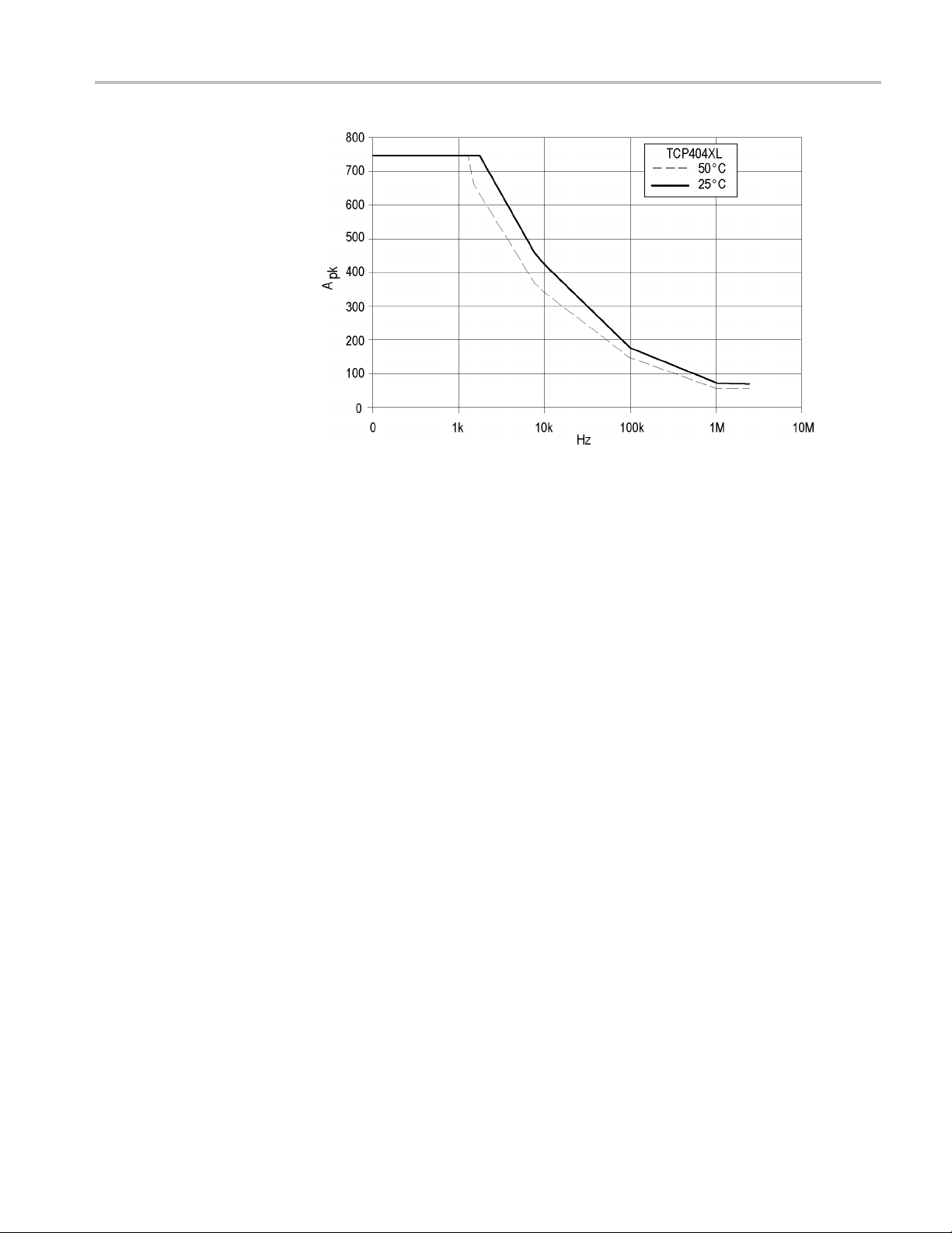
Figure 32: Frequency derating-TCP404XL
Specifications
TCPA300/400 Amplifiers and TCP300A/400 Series Current Probes User Manual 55
Page 74

Specifications
Figure 33: Insertion impedance versus frequency
56 TCPA300/400 Amplifiers and TCP300A/400 Series Current Probes User Manual
Page 75
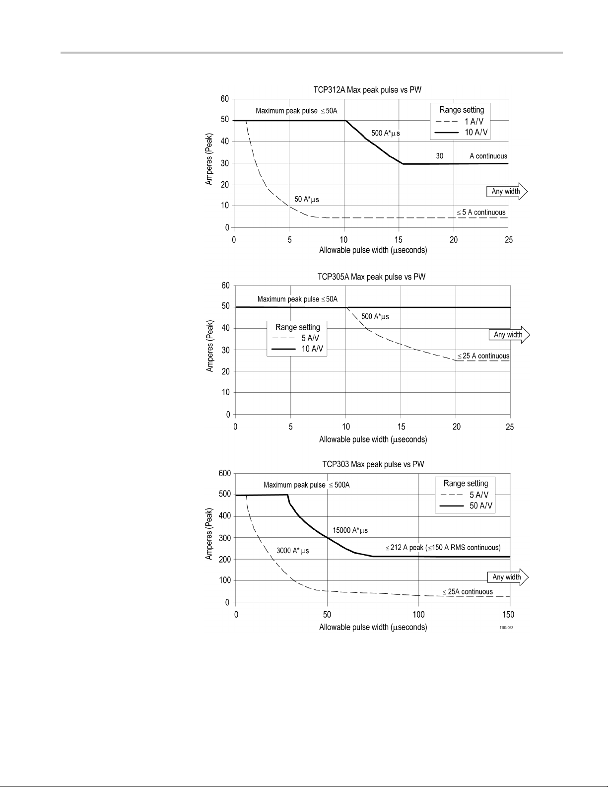
Specifications
ure 34: Specified operating area of the probes
Fig
TCPA300/400 Amplifiers and TCP300A/400 Series Current Probes User Manual 57
Page 76
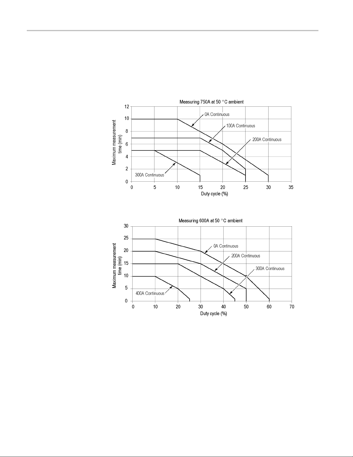
Specifications
TCP404XL Maxi
mum Measurement Times
The m aximum measurement time for the TCP404XL probe with varying duty
cycles and temperatures are shown in the following three graphs. Details about the
relationshi
Noncontinuous Current with the TCP404XL Probe.)
Figure 35: Measuring 750A noncontinuous at 50 °C ambient temperature
p between measurement factors are available. (See page 30, Measuring
Figure 36: Measuring 600A noncontinuous at 50 °C ambient temperature
58 TCPA300/400 Amplifiers and TCP300A/400 Series Current Probes User Manual
Page 77

Specifications
Figure 37
At 23 deg
the TCP404XL probe.
Emissio
equipment is connected to a test object.
: Measuring 750A noncontinuous at 23 °C ambient temperature
rees ambient temperature, 600 A can be measured continuously with
ns which exceed the levels required by this standard may occur when this
TCPA300/400 Amplifiers and TCP300A/400 Series Current Probes User Manual 59
Page 78

Specifications
60 TCPA300/400 Amplifiers and TCP300A/400 Series Current Probes User Manual
Page 79

Glossary
amp-second product
The unit of measure defining the maximum amount of pulsed current that can
be measured before the probe core becomes saturated. The amp-second rating
applies only to measurement values between the maximum continuous and
maximum pul
to the peak current multiplied by the pulse width at the 50% point.
auto-balance
A process that removes unwanted DC offsets from the TCPA300 and
TCPA400 circuitry to ensure maximum measurement accur
is performed during the probe degauss routine.
bucking current
Current fed back by the TCPA300 and TCPA400 to the current probe during
DC and low-frequency AC measurements. Bucking current nulls most of the
magnetic fi eld in the probe core, allowing linear DC and AC measurements
simultaneously.
conventional current flow
se current ratings of the probe. The amp-second rating is e qual
acy. This process
The flow of the positive charge in a conductor. Conventional current flow is
from positive to negative. The arrows on current probes point in the direction
of conventional current flow. C onventional current fl ow is in the opposite
direction of electron current flow.
degauss
A process of eliminating residual magnetism from the probe core by feeding
a decaying sine wave into the core. The degaussing process should be
performed before clamping the probe around a conductor, whenever the probe
becomes saturated by current overloads, or whenever the probe is exposed
to a magnetic field. The term is derived from one of the units of magnetic
flux density.
electron current flow
The flow of the electrons in a conductor. Electron current flow is from
negative to positive. The arrows on current probes point in the opposite
direction of electron current flow. Electron current flow is in the opposite
direction of conventional current flow.
flux
The density of a magnetic field. As the number of flux lines increases,
the magnetic field strength increases. Current in the conductor under test
generates flux lines in the probe core by inducing a voltage in the core.
TCPA300/400 Amplifiers and TCP300A/400 Series Current Probes User Manual 61
Page 80

Glossary
Hall device
A thin, rectangular piece of semiconductor material located in the core of the
current probe
AC measurements.
Hall effect
The effect that produces a voltage potential in the Hall device when magnetic
lines of flux pass through the device. The voltage potential is directly
proportional to the magnetic field strength. The voltage polarity is determined
by the magn
effect. The TCP300 and TCP400 Series current probes use the Hall effect for
DC and low-frequency AC measurements.
insertion impedance
The equivalent series impedance introduced to a test circuit when the current
probe is clamped around a test conductor.
magnetic susceptibility
. The Hall device uses the Hall effect for DC and low-frequency
etic field polarity. A bias supply is required to produce the Hall
A figure expressing the amount of current induced into the probe by an
external magnetic field of known intensity. The lower the figure is, the less
the probe is influenced by external magnetic fields.
ration
satu
A condition that occurs when the magnetic field strength in the probe core
eeds the maximum level that the core can absorb. When saturation occurs
exc
the probe no longer responds linearly to an increase in magnetic field strength,
resulting in measurement inaccuracies. A current overload condition will
cause core saturation. After saturation occurs, the probe core usually retains
residual magnetism, which continues to produce inaccuracies until the probe
is degaussed. The probe should be degaussed after saturation occurs.
62 TCPA300/400 Amplifiers and TCP300A/400 Series Current Probes User Manual
Page 81

Index
A
AC coupling, 15, 20, 26
amp-second p
Amp-second product, 27
Applications, 35
auto-balance, 61
Autobalance function, 18
roduct, 61
B
bucking current, 61
Bucking c
Button
urrent, 32
COUPLING, 20
MANUAL BALANCE, 19
ON/STANDBY, 20
PROBE DEGAUSS/
AUTOB
RANGE, 20
ALANCE, 18
C
Connecting
a current probe to a circuit
under test, 14
a current probe to the
lifier, 9
amp
the amplifier to an
oscilloscope, 8
Connector
OUTPUT, 21
PROBE INPUT, 21
Continuity measurements, 39
Control summary, 17
conventional current, 61
See also electron current
COUPLING button and
indicator, 20
Coupling modes, 26
Current limitations
amp-second product, 27
maximum continuous, 27
maximum pulsed, 27
D
DC coupling, 20, 26
DC gain adjus
DC LEVEL control, 26
degauss function, 61
Degauss function, 12, 18, 23
Differential current, 24
t, optimizing, 21
E
electron current, 61
See also c
Error codes
correcting, 47
Error Codes
displaying, 45
shutdown error, 47
ding the current range of the
Exten
probes, 32
onventional current
F
flux, 61
Frequency derating, 27
Front panel controls, 17
G
Gauss, 61
IB operation, 22
GP
H
Hall device, 62
Hall effect, 62
I
Increasing bucking current, 32
Increasing probe sensitivity, 34
Indicator
COUPLING, 20
MANUAL BALANCE, 19
NONCOMPATIBLE PROBE
TYPE, 20
NOT TERMINATED INTO
50 OHMS, 20
OVERLOAD, 19
PROBE DEGAUSS/
AUTOBALANCE, 18
PROBE OPE
RANGE, 20
Inductance measurements, 37
insertion impedance, 62
N, 19
M
MANUAL BALANCE buttons
and indicator, 19
Maxim
Maximum continuous current
Maximum measurement time s, 30
Maximum pulsed current
Measuring continuity, 39
Measuring current
Measuring inductance, 37
um allowable pulse
amplitude, 29
rating, 27
ting, 27
ra
AC, 15
current nulls, 24
DC, 13
differential current, 24
N
NONCOMPATIBLE PROBE
TYPE
indicator, 20
NOT TERMINATED INTO 50
OHMS indicator, 20
Null current, 24
TCPA300/400 Amplifiers and TCP300A/400 Series Current Probes User Manual 63
Page 82

Index
O
ON/STANDBY button, 20
Optional acc
Options, 3
OUTPUT connector, 2 1
OVERLOAD indicator, 19
essories, 4
P
Power on the ampli fi er, 8
Probe cover, 5
PROBE
DEGAUSS/AUTOBALANCE
button and indicator, 18
PROBE
DEGAUSS/AUTOBALANCE
indicator, 18
PROBE I
NPUT connector, 21
PROBE OPEN indi
Probes
coupling, 26
degaussing
(demagnetizing), 12,
18
descriptio
extending the current
range, 32
increasing the current
limit, 32
maximum current limits, 27
operatin
saturation, 27
g the probe slide, 10
cator, 19
n, 2
R
RANGE button and indicator, 20
S
Safety Summary, v
saturation,
Shutdown error, 47
Specifications, 49
Standard accessories, 4
susceptibility, 62
62
T
TCP404XL
maximum m
times, 30, 58
TEKPROBE-to-TEKPROBE
interface cable, 8
Termination, 50 Ω feedthrough, 8
Travel case, 7
Troubl
eshooting, 42
easurement
64 TCPA300/400 Amplifiers and TCP300A/400 Series Current Probes User Manual
 Loading...