

Page 1

Instruction Manual
TCP202
15 Ampere AC/DC Current Probe
070-9542-02
www.tektronix.com
Page 2

Copyright © Tektronix, Inc. All rights reserved.
Tektronix products are covered by U.S. and foreign patents, issued and
pending. Information in this publication supercedes that in all previously
published material. Specifications and price change privileges reserved.
Tektronix, Inc., P.O. Box 500, Beaverton, OR 97077
TEKTRONIX and TEK are registered trademarks of Tektronix, Inc.
Page 3

WARRANTY
Tektronix warrants that the products that it manufactures and sells will be free from defects
in materials and workmanship for a period of one (1) year from the date of purchase from
an authorized Tektronix distributor. If any such product proves defective during this
warranty period, Tektronix, at its option, either will repair the defective product without
charge for parts and labor, or will provide a replacement in exchange for the defective
product. Batteries are excluded from this warranty.
In order to obtain service under this warranty, Customer must notify Tektronix of the defect
before the expiration of the warranty period and make suitable arrangements for the
performance of service. Customer shall be responsible for packaging and shipping the
defective product to the service center designated by Tektronix, shipping charges prepaid,
and with a copy of customer proof of purchase. Tektronix shall pay for the return of the
product to Customer if the shipment is to a location within the country in which the
Tektronix service center is located. Customer shall be responsible for paying all shipping
charges, duties, taxes, and any other charges for products returned to any other locations.
This warranty shall not apply to any defect, failure or damage caused by improper use or
improper or inadequate maintenance and care. Tektronix shall not be obligated to furnish
service under this warranty a) to repair damage resulting from attempts by personnel other
than Tektronix representatives to install, repair or service the product; b) to repair damage
resulting from improper use or connection to incompatible equipment; c) to repair any
damage or malfunction caused by the use of non-Tektronix supplies; or d) to service a
product that has been modified or integrated with other products when the effect of such
modification or integration increases the time or difficulty of servicing the product.
THIS WARRANTY IS GIVEN BY TEKTRONIX WITH RESPECT TO THE
LISTED PRODUCTS IN LIEU OF ANY OTHER WARRANTIES, EXPRESS OR
IMPLIED. TEKTRONIX AND ITS VENDORS DISCLAIM ANY IMPLIED
WARRANTIES OF MERCHANTABILITY OR FITNESS FOR A PARTICULAR
PURPOSE. TEKTRONIX’ RESPONSIBILITY TO REPAIR OR REPLACE
DEFECTIVE PRODUCTS IS THE SOLE AND EXCLUSIVE REMEDY
PROVIDED TO THE CUSTOMER FOR BREACH OF THIS WARRANTY.
TEKTRONIX AND ITS VENDORS WILL NOT BE LIABLE FOR ANY
INDIRECT, SPECIAL, INCIDENTAL, OR CONSEQUENTIAL DAMAGES
IRRESPECTIVE OF WHETHER TEKTRONIX OR THE VENDOR HAS
ADVANCE NOTICE OF THE POSSIBILITY OF SUCH DAMAGES.
Page 4

Contacting Tektronix
Phone 1-800-833-9200*
Address Tektronix, Inc.
Department or name (if known)
14200 SW Karl Braun Drive
P.O. Box 500
Beaverton, OR 97077
USA
Web site www.tektronix.com
Sales
support
Service
support
Technical
support
* This phone number is toll free in North America. After office
hours, please leave a voice mail message.
Outside North America, contact a Tektronix sales office or
distributor; see the Tektronix web site for a list of offices.
1-800-833-9200, select option 1*
1-800-833-9200, select option 2*
Email: techsupport@tektronix.com
1-800-833-9200, select option 3*
6:00 a.m. -- 5:00 p.m. Pacific time
Page 5

Table of Contents
General Safety Summary iii............................
Getting Started 1.....................................
Features and Accessories 1..............................
Installation 3.........................................
Compensating the Probe (Optional) 4.....................
Operating Basics 5...................................
Measurement Limits 5.................................
Precautions for Uninsulated Conductors 5..................
Maximum Current Rating 5.............................
Multiple Current Probes 6..............................
Degaussing and Balancing the Probe 6....................
Measurement Procedures and Techniques 7.................
Basic Procedure 7.....................................
Measuring Differential Current 8.........................
Extending the DC Current Ra nge 10.......................
Increasing Measurement Sensitivity 12.....................
Reference 13.........................................
Power Measurements 13.................................
Inductance Measurements 14.............................
Low-Impedance Pulse Sources 14.........................
High-Impedance Pulse Sources 16.........................
Continuity Test of Multiple-Conductor Cable 18.............
Measuring Induc tor Turns Count 18........................
Specifications 20......................................
Warranted Characteristics 20.............................
Typical Characteristics 22...............................
Nominal Characteristics 27..............................
Maintenance 29.......................................
Cleaning the Probe Head 29..............................
Servicing the Compensation Box 30.......................
Probe Head Disassembly 34..............................
Obtaining Replacement Parts 38..........................
Preparation for Shipment 39..............................
Performance Verification and Adjustment 40..............
TCP202 Instruction Manual
i
Page 6

Table of Contents
Test Procedure Conditions 40.............................
Equipment Required 40.................................
DC Accuracy 41.......................................
Bandwidth 42.........................................
List of Figures
Figure 1: TCP202 Current Probe 1......................
Figure 2: Coarse Balance Adjustment 3..................
Figure 3: Connecting the Calibrator 4...................
Figure 4: Polarity of Current Flow 8....................
Figure 5: Measuring Differential Current and Nulls 9......
Figure 6: Increasing the DC Measurement Range 11........
Figure 7: Increasing Probe Sensitivity 12..................
Figure 8: Measuring Inductance with a
Low-Impedance Source 15...........................
Figure 9: Linear Current versus Time Ramp 16............
Figure 10: Measuring Inductance with a
High-Impedance Source 17..........................
Figure 11: High-Impedance Source Current Ramp 17.......
Figure 12: Measuring the Number of T urns in a Coil 19.....
Figure 13: Turns Measurement Using Reference Coil 19.....
Figure 14: Frequency Derating 23.......................
Figure 15: Insertion Impedance -- Magnitude -- Single
Conductor 23......................................
Figure 16: Insertion Impedance -- Phase Angle -- Single
Conductor 24......................................
Figure 17: Insertion Impedance -- Magnitude --
10-Turn #24 AWG Primary 25........................
Figure 18: Insertion Impedance -- Phase Angle -- 10-Turn #24
AW G P r im a r y 2 6...................................
Figure 19: Current Ratings 27...........................
ii
TCP202 Instruction Manual
Page 7

Table of Contents
Figure 20: Replacing TekProbe Interface Pins 30...........
Figure 21: Replacing the TekProbe collar 31...............
Figure 22: Removing the Compensation Box Covers 32......
Figure 23: Accessing the Gain Adjustment 33..............
Figure 24: Replacing the Compensation Box Cover 34......
Figure 25: Removing the Strain Relief Boot 35.............
Figure 26: Removing the Top Half of the Probe 36..........
Figure 27: Removing the Probe Slide 37..................
Figure 28: Removing the Current Transformer 38..........
Figure 29: TCP202 and Replaceable Accessories 46.........
Figure 30: Replaceable Parts -- Compensation Box 48.......
Figure 31: TCP202 Optional Accessories 50...............
TCP202 Instruction Manual
iii
Page 8

Table of Contents
iv
TCP202 Instruction Manual
Page 9
General Safety Summary
Review the following safety precautions to avoid injury and prevent
damage to this product or any products connected t o it.
Injury Precautions
Do Not Operate in Wet/Damp C onditions. To avoid electric shock, do not
operate this product in wet or damp conditions.
Do Not Operate in an Explosive Atmosphere. To avoid injury or fi re
hazard, do not operate this product in an explosive atmosphere.
Observe Maximum Working Voltage. Do not use this product on bare
wires above 300 V (DC + peak AC).
Product Damage Precautions
Do Not D rop the Probe Head. The probe head contains fragile
components that can be damaged by a high impact. Take care to
prevent the probe head from dropping on the floor or other hard
surface. Secure the probe head in a safe location when not in use.
Do Not Operate With Suspected Failures. If you suspect there is damage
to this product, have it i nspected by qualified service personnel.
Do Not Immerse in Liquids. Clean the probe using only a damp cloth.
Refer to cleaning instructions.
Safety Terms and Symbols
Terms in This Manual. These terms may appear in this manual:
WARNING. Warning statements identify conditions or pract ices that
could result in injury or loss of life.
CAUTION. Caution statements identify condit ions or practices that
could result in damage to this product or other property.
TCP202 Instruction Manual
v
Page 10
General Safety Summary
Terms on the Product. These terms may appear on the product:
DANGER indicates an injury hazard immediately accessible as you
read the marking.
WARNING indicates an injury hazard not immediately accessible as
you read the marking.
CAUTION indicates a hazard to property including the product.
Symbols on the Product. These symbols may appear on the product:
CAUTION
Refer to Manual
Do not connect to or
remove from an
uninsulated conductor t hat
is HAZARDOUS LIVE.
WARNING
High Voltage
Breakable.
Do not drop.
Double
Insulated
Use only on an
insulated wire.
Protective Ground
(Earth) Terminal
Certifications and Compliances
Refer to the specifications section for a listing of certifications and
compliances that apply to this product.
vi
TCP202 Instruction Manual
Page 11
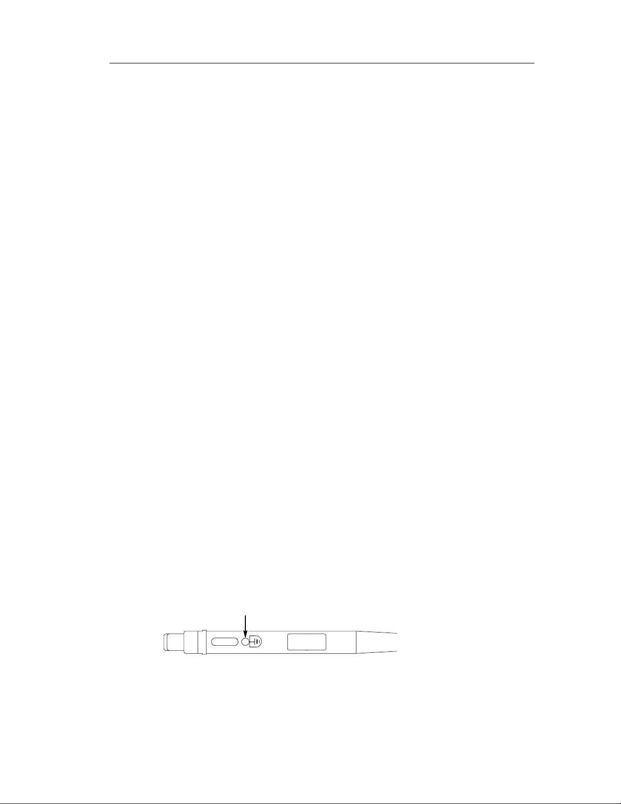
Getting Started
This section describes the TCP202 Current Probe and gives
instructions on how to install and functiona lly test the probe.
Features and Accessories
The TCP202 Current Probe (Figure 1) is a 50 MHz current probe for
use with Tektronix oscilloscopes that have the TekProbe interface.
The probe can measure up to 15 A (DC + peak AC).
Figure 1: TCP202 Current Probe
TCP202 Instruction Manual
1
Page 12
Getting Started
Probe Head. The probe head contai ns a Hall Effect
device for measuring current. T he j aw of the probe
clamps on any wire (including insulation) that is less
than or equal to 3.8 mm (0.15 inches) in diameter.
TekProbe Interface. The TekProbe interface provides
power, signal, and probe characteristic data.
If your oscilloscope does not support the TekProbe
interface, you can use the optional 1103 probe power
supply as an effective interface. Contact your local
Tektronix representative for more information.
Degauss. The degauss button re moves residual
magnetism from the probe core that would otherwise
cause measurement errors.
Balance Thumbwheel. The balance t humbwheel
compensates for minor DC offsets of the probe output.
Coarse Balance Adjustment. Thecoarsebalance
adjustment centers the range of the balance thumbwheel. Use this adjustment onl y if the thumbwhee l
does not have enough range.
Calibrator (optional). With some TDS oscilloscopes, you
can compensate the probe for maximum accuracy using
the optional calibrator. Use the calibrator only if your
oscilloscope displays the AΩ symbol when the current
probe is connected. (For ordering information, see
Replaceable Parts startingonpage44.)
2
TCP202 Instruction Manual
Page 13
Installation
Install the TCP202 Current Probe as follows:
1. Set the input channel to a zero reference point.
2. Connect the output of the probe to the TekProbe interface of the
If your TDS oscilloscope does not display amperes/division, interpret
volts/division as amperes/division.
If you are using the 1103 TekProbe Power Supply, you must set the
oscilloscope input coupling to DC and the input impedance t o 50 Ω.
Interpret V/division as 10 A/division. For example, interpret
100 mV/division as 1 A/division.
Getting Started
oscilloscope or other measurement instrument. The measurement
instrument input must have a ground reference.
3. With the probe jaw empty, push the slide on the probe until it
locks in the CLOSED position.
4. Press the DEGAUSS button.
5. Balance the probe as follows:
a. Set the oscilloscope vertical scale to 10 mA/division.
b. Open and close the probe jaw.
c. Adjust the BALANCE thumbwheel until the displayed
signal is zero.
6. If you cannot zero the display as described in step 5c, use the
coarse balance adjustment (Figure 2) to center the range of the
thumbwheel.
Coarse balance
Figure 2: Coarse Balance Adjustment
TCP202 Instruction Manual
3
Page 14
Getting Started
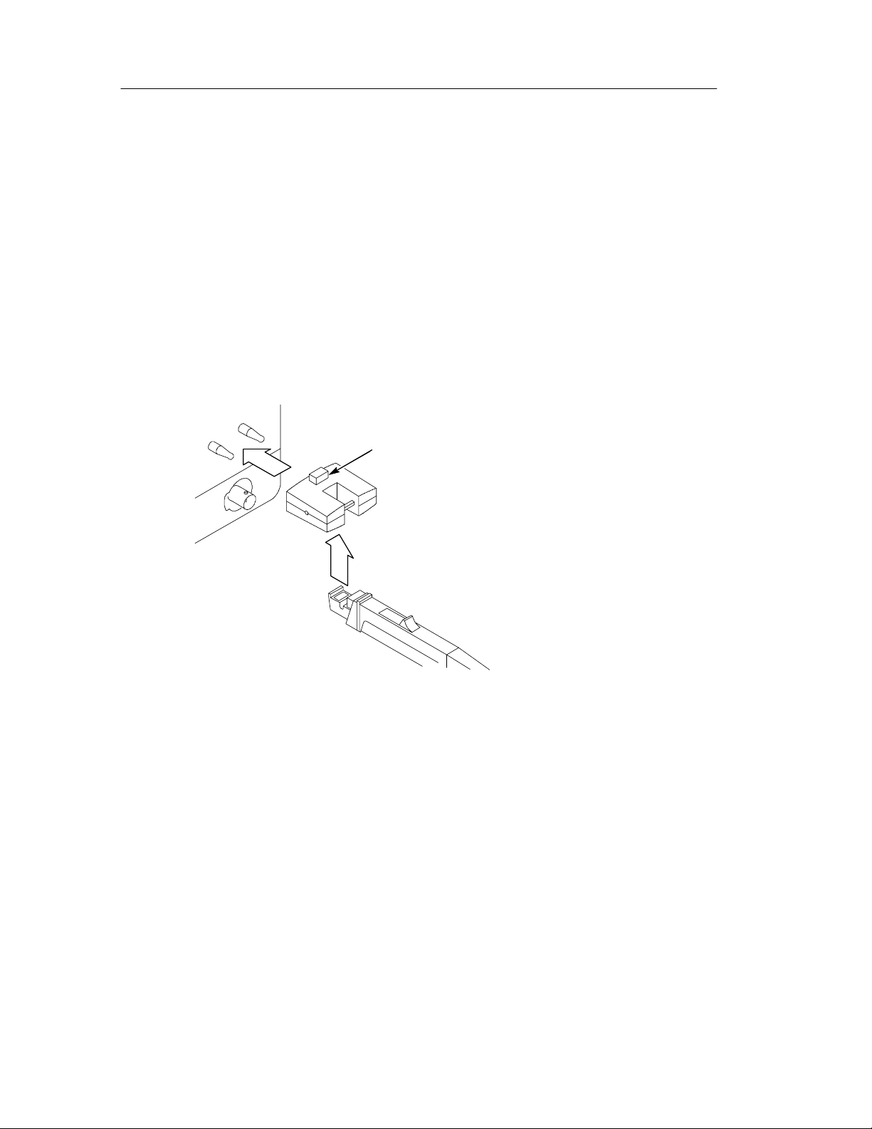
Compensating the Probe (Optional)
With some TDS oscilloscopes, you can compensate the probe for
maximum accuracy using the optional calibrator. Perform this
procedure only if your oscilloscope displays the AΩ symbol when
you connect the probe output to the oscilloscope input.
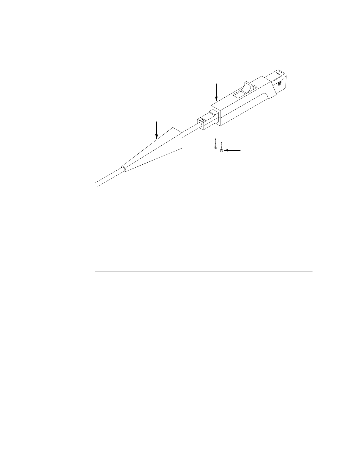
1. To connect the calibrator, press the release button (Figure 3) and
connect the calibrator to the probe compensation output of the
oscilloscope.
Release button
Figure 3: Connecting the Calibrator
2. Close and lock the probe jaw over the calibrator loop.
3. Adjust the oscilloscope to display the signal.
4. Press VERTICAL MENU→Cal Probe→OK Compensate Gain.
If the probe passes the compensation routine, the probe is accurate to
within ± 1%from50mAto5Aand± 2% from 5 A to 15 A.
If the probe fails the compe nsation routine, refer to the procedure for
checking the DC accuracy of the probe on page 41 and the procedure
for accessing the internal gain adjustment on page 32.
Repeat this procedure whenever you move the current probe to
another input.
4
TCP202 Instruction Manual
Page 15
Operating Basics
This section contains important precautions and techniques for
clamping the probe on a circuit and taking basic measurements.
Measurement Limits
Before you clamp the probe on a circuit to measure curre nt, observe
the precautions for uninsulated wires and the maximum current
ratings.
Precautions for Uninsulated Conductors
WARNING. To avoid ele ctrical shock from uninsulat ed conductors,
observe t he following precautions:
Disconnect the power to the uninsulated conductor before inserting
the conductor in or removing the conductor from t he probe jaw.
Do not apply a voltage higher than 300 V (DC + peak AC) between
earth ground and an uninsulated conductor that is in the probe jaw.
Maximum Current Rating
There are two basic current ratings: maximum pe ak current and
maximum continuous current. In addition, the maximum peak
current is limited by the A/second rating. For a graph of these limits,
refertoFigure19onpage27.
The maximum peak current is 50 A with a pulse width ≤ 10 s
(500 Aseconds). This 500 Aseconds rating applies to any peak
current over 15 A. The product of the peak current and pulse width
(at 50% of peak) must be 500 Aseconds or le ss. For example, the
maximum pulse width is 20 s for a pulse of 25 A peak.
TCP202 Instruction Manual
5
Page 16

Operating Basics
The maximum continuous current that this probe can measure is
15 A (DC + peak AC). This limit derates with frequency; as the
frequency increases, the maximum current rating decreases. For a
graph of this relationship, see Figure 14 on page 23.
Multiple Current Probes
Up to four TCP202 current probes may be used simultaneously on
one TDS Series oscilloscope if the total in-phase current measured
by all of the probes does not exceed 40 amperes. Above 40 amperes,
the TekProbe interface may overload and cause measurement or
display errors.
When one or two TCP202 current probes are used on a TDS Serie s
oscilloscope, the ratings are as shown in Figure 19 on page 27.
Degaussing and Balancing the P robe
For accurate measurements, you must occasionally degauss and
balance the probe. Degaussing removes residual magnetization from
the probe core that would otherwise shift the zero point and cause
measurement errors. Balancing the probe compensates for any DC
offset that remains on the probe output after degaussing.
Degauss and balanc e your probe in each of the following cases:
H After turning on the oscilloscope and allowing a 20-minute
warm-up period
H Whenever an overload condition occurs
H Whenever the probe is subjected to a strong external magnetic
field
H Whenever there is a measurable DC offset that does not come
from the conductor under test
To degauss and balance the probe, follow the installation procedure
on page 3.
You may degauss the probe with a conductor in the jaw if you first
disconnect the power to the conductor. This technique compensates
for any offsets caused by stray DC magnetic fields around the circuit
under test.
6
TCP202 Instruction Manual
Page 17

CAUTION. While degauss occurs, the probe will induce a small
voltage in the unpowered circuit (33 mV in series with 1.5 MΩ). Your
circuit must be able to absorb this induced voltage. With low
impedance circuits, several amperes may be induced in the circuit
being measured. This may be of concern if you are using very small
conductors.
Measurement Procedures and Techniques
This section presents procedures and techniques for basic current
measurements.
Operating Basics
Basic Procedure
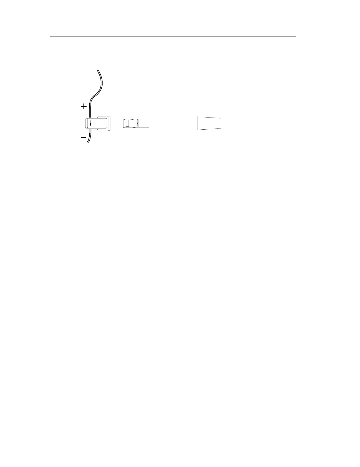
Measure AC or DC current in a single conductor as follows:
1. Observe the safety precautions and operating limits.
2. If necessary, degauss and balance the probe.
3. Close and lock the probe jaw over the conductor. Conventional
current flows from positive to negative. For the correct polarity
reading, connect the probe so that the current flow, from positive
to negative, is aligned with the arrow on the probe jaw (see
Figure 4).
4. Read the measurement. Adjust the display of the measurement
instrument as necessary.
5. If necessary, adjust the oscilloscope offset control to offset a DC
level. (AC coupling is automatically disabled on TDS oscilloscopes when the probe is connected.)
TCP202 Instruction Manual
7
Page 18
Operating Basics
Figure 4: Polarity of Current Flow
Measuring Differential Current
You can place two conductors in a current probe to provide a
differential or null current measurement. This avoids the necessity of
using two current measurement systems with a differential
oscilloscope amplifier.
1. Orient the two conductors under test so that the pol arities oppose
each other. Clamp the current probe around the two conductors as
shown in Figure 5.
2. Measure the current. A waveform above the baseline indicates
the conductor with the conventional current flow in the direction
of the probe arrow is carrying the greater current.
3. To adjust for a current null, adjust the current in one of the
conductors until the displayed measurement is zero.
8
TCP202 Instruction Manual
Page 19
Conductor 1
Operating Basics
Conductor 2
Current
Current
Current probe
Figure 5: Measuring Differential Current and Nulls
TCP202 Instruction Manual
9
Page 20

Operating Basics
Extending the DC Current Range
You may encounter situa tions where your measurement exceeds t he
maximum current rating of the connected probe. This section
discusses methods for e xtending DC current ranges without
exceeding specified limits.
WARNING. To avoid personal injury or equipment damage, do not
exceed the specified electrical limits of the oscilloscope or any
applicable accessories. When using multiple conduct ors, do not
exceed current limits on either conductor.
If you want to measure a low-amplitude AC component that is
superimposed on an extremely large steady state DC component
(such as in a power supply), or if you want to extend the DC current
range of your probe, you can add offset (bucking) current with a
second conductor.
By adding bucking current, the amount of DC current that you
measure is the difference between the DC component of the signal
and the bucking current. You can then calculate the amount of DC
current in the conductor under test by adding the value of the
measured current to the value of the bucking current.
To supply additional bucking current, place a second conduc tor that
has a pure DC component of known value in the probe jaw with the
conductor under test, as shown in Figure 6(a) on pa g e 11. Orient the
second conductor so that the bucking current fl ows in the opposit e
direction of the DC flow in the conductor under test.
You can increase the value of the bucking current by winding
multiple turns of the second conduct or around the probe, as shown in
Figure 6(b) on page 11. The bucking current is equal to the current
flowing in the conductor, multiplied by the number of turns wound
around the probe. For example, if the second conductor has a current
of 100 mA DC and is wrapped around the probe five times, the DC
bucking current is 100 mA multiplied by 5, or 500 mA DC.
10
TCP202 Instruction Manual
Page 21

Operating Basics
NOTE. Adding a second conductor to the probe reduces the upper
bandwidth limit of the probe.
Current
Current
Conductor
under test
Second conductor
suppling bucking
current
Current probe
(a) Adding a second conductor
Current
Current
Extra turns added
to increase
Current probe
bucking current
(b) Adding multiple turns
Figure 6: Increasing the DC Measurement Range
Conductor
under test
TCP202 Instruction Manual
11
Page 22

Operating Basics
Increasing Measurement Sensitivity
If you are measuring DC or low-frequency AC signals of very small
amplitudes, you can increase measurement sensitivity of your
Current Probe by winding several turns of the conductor under test
around the probe as shown in Figure 7. The signal is multiplied by
the number of turns around the probe.
When viewing the signal on the oscilloscope screen, divide the
displayed amplitude by the number of turns to obtain the actual
current value. For exampl e, if a conductor is wrapped around the
probe five times and the oscilloscope shows a reading of 50 mA DC,
the actual current flow is 50 mA divided by 5, or 10 mA DC.
NOTE. Winding multiple turns around the probe increases the
insertion impedance of the probe which can affect the accuracy of
your measurements and the circuit under test. For graphs of insertion
impedance, refer to figures 15 and 17 on page 23.
12
Conductor
under test
Extra turns for
increased sensitivity
Current probe
Figure 7: Increasing Probe Sensitivity
TCP202 Instruction Manual
Page 23

Reference
This section describes extended measurement applications of the
TCP202 Current Probes:
H Power Measurements
H Inductance Measurements
H Continuity Test of Multiple-Conductor Cable
H Measuring Inductor Turns Count
Power Measurements
You can measure the instantaneous power deli vered to the load of a
two-wire circuit using a digital oscilloscope that allows you to
multiply two channels.
1. Connect the output of a differential voltage probe (such as the
P5205) to one channel and the output of the TCP202 Current
Probe to the other channel of the oscilloscope.
NOTE. For high-frequency measurements, the time (propagation)
delays of both probes should match. (The P5205 and TCP202 probes,
for example, have matc hing propagation delays.) You can also use
the deskew function available on some TDS oscilloscopes to match
the time delays.
2. Connect the + input of the differential probe to the first terminal
and -- input to the second (reference) terminal.
3. Close and lock the current probe around the conductor of the first
terminal with the arrow on the probe head pointing in the
direction of the reference.
4. So that the voltage and current waveforms are phase-related,
select only one channel as the trigger source and acquire the two
waveforms.
TCP202 Instruction Manual
13
Page 24

Reference
5. After acquiring the current and voltage waveforms, set the two
channels to multiple together. (On the TDS Series oscilloscopes
that have this capability, select MORE→Change Math waveform
definition→Dual Wfm Math→Set operator to *→OK Create
Math Wfm.) The oscilloscope displays the power waveform.
Other functions on TDS oscilloscopes allow you to measure the
average power for one cycle (Cycle Mean) or the average power for
the entire record (Mean). Refer to the user manual of your oscilloscope for more information.
Inductance Measurements
You can use the current probe to measure the inductance of coils that
have either a low-impedance or high-impedance pulse source of a
known value.
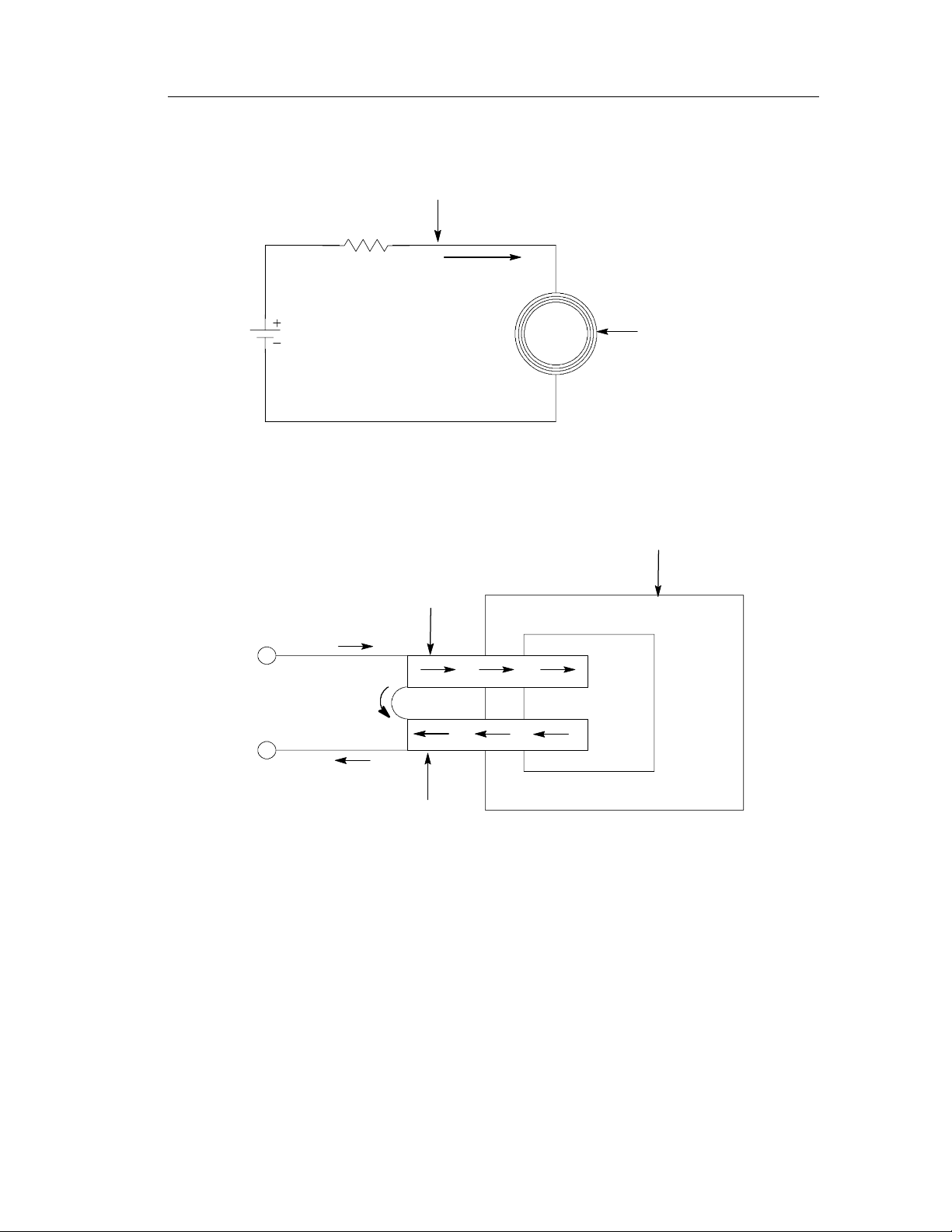
Low-Impedance Pulse Sources
Figure 8 shows a measurement setup using a constant-voltage pulse
generator of extremely low output impedance connected to an
inductor that has low resistance. The inductor is connected across the
output terminals of the pulse source and a constant voltage is
maintained across the inductor. The current probe is clamped over
one of the source leads and the current ramp is measured.
The inductance is effectively de fined by the slope of the current
ramp, shown in Figure 9, and is mathematically expressed by the
following formula:
− E
L =
di
dt
where L is the inductance in henries, E is the voltage of the pulse
generator, dt is the change in time, and di is the change in current.
14
TCP202 Instruction Manual
Page 25

Reference
Pulse
generator
Current
probe
Current
flow (i)
Inductor (L)
Figure 8: Measuring Inductance with a Low-Impedance Source
NOTE. If the probe impedance is a significant part of the total circuit
inductance, measurement accuracy will be affected. Refer to the
probe specifications for probe insertion impedance.
TCP202 Instruction Manual
15
Page 26

Reference
Current flow (i)
d
i
Time (t)
d
t
Figure 9: Linear Current versus Time Ramp
High-Impedance Pulse Sources
If the pulse source has a higher im pedance of known resistance, such
that the output voltage drops as the current increases, the inductance
of a coil can be calculated by the time constant of the charge curve.
Figure 10 shows the setup diagram, which is similar to the previous
example. The current ramp represented in Figure 11 shows how the
values for the inductance formula are obtained.
Use this formula to calculate the inductance based on the curre nt
measurement:
L = τ R
where L is the inductance in henries, τ is the time required for the
current to rise or fall 63.2% of the total current value, and R is the
source resistance of the pulse generator.
16
TCP202 Instruction Manual
Page 27

Resistance (R)
Reference
Pulse
generator
Current
probe
Current
Flow (i)
Inductance (L)
Figure 10: Measuring Inductance with a High-Impedance Source
Current flow (i)
100%
63.2%
36.8%
0
Figure 11: High-Impedance Source Current Ramp
TCP202 Instruction Manual
Time (t)
ττ
17
Page 28

Reference
Continuity Test of Multiple -Conductor Cable
You can test single conductors in a multiconductor cable. To check a
conductor, clamp the current probe around the cable bundle and
check for a specific, known curre nt signal. If there is no current or
the current is abnormally low, then the conductor ha s a continui ty
problem. If the current is abnormally high, then the conductor may
have a short to ground.
Measuring Inductor Turns Count
To obtain an approximate turns count of an inductor, connect the
inductor to a current limited source, as shown in Figure 12. Measure
the input current on one of the inductor leads, then clamp the current
probe around the inductor and note the current value. The number of
turns is equal to the ratio of coil current to input current. The
accuracy of this method is limited by the current measurement
accuracy. The following method allows more precise turns
measurement.
For a more precise turns count, you need a coil with a known number
of turns to use as a reference. The measurement setup is similar to
that previously described, except the reference coil and the test coil
are inserted into the current probe so that the currents oppose each
other (see Figure 13). You must observe the pol arity of coil current to
determine whether the test coil has more or fewer turns than the
reference coil. The turns are calculated by using the formula:
I
= N1×
N
2
m
I
1
where N2is the number of turns in the test coil, N1is the number of
turns in the reference coil, I
is the measured coil current, and I1is
m
the input current.
18
TCP202 Instruction Manual
Page 29
Measure input current here
Current flow (i)
Coil
Figure 12: Measuring the Number of Turns in a Coil
Reference
Clamp probe
around coil to
measure
current from
coil turns
TCP202 Current probe
Current flow
in coil 1
Input current
Current flow
in coil 2
Figure 13: Turns Measurement Using Reference Coil
TCP202 Instruction Manual
19
Page 30

Specifications
The specifications in Tables 1 through 4 apply to a TCP202 Current
Probe installed on a Tektronix TDS 520B Oscilloscope. The tables
also list the specifications for the c alibrator (page 50) that can be
used on some TDS oscilloscopes to increase the DC accuracy.
When the probe is used with another oscilloscope, the oscilloscope
must have a bandwidth of at least 200 MHz. Oscilloscopes without
the TekProbe interface must use a Tektronix 1103 TekProbe Power
Supply.
The probe must have a warm-up period of at least 20 minutes and be
in an environment that does not exceed the limits described in
Table 1.
Specifications for the TCP202 Current Probe fall into three
categories: warranted, typical, and nominal characteristics.
Warranted Characteristics
Warranted characteristics (tables 1 and 2) describe guaranteed
performance within tolerance limits or certain type-tested requirements. Warranted characteristics that have checks in the Perfor-
mance Verification and Adjustment section appear in boldface type.
Table 1: Warranted Electrical Characteristics
DC Accuracy ± 3%
(correctable to ± 1% from 50 mA to 5 A and ± 2% from 5 A
to 15 A when used with calibrator on self-calibrating TDS
series oscilloscopes)
Calibrator Resistance
Calibrator Amp-turns 0.500 Amp-turns
System Bandwidth DC to 50 MHz (oscilloscope bandwidth ≥ 200 MHz)
System Rise Time < 7 ns (oscilloscope rise time < 1.75 ns)
42 Ω
20
TCP202 Instruction Manual
Page 31

Table 1: Warranted Electrical Characteristics (Cont.)
Specifications
Maximum DC and Low
Frequency Current
(See Figure 19)
Maximum Peak Current
(See Figure 19)
Maximum Voltage on Uninsulated Wire
Temperature
Humidity
15 A (DC + peak AC)
50 A with pulse width ≤ 10 s
300 V (DC + peak AC), CAT I
Operating: +5 to +50_ C
Nonoperating: --10 to +60_ C
Operating: tested at 90 to 95% RH, +30_ to +50_ C
Nonoperating: tested at 90 to 95% RH, +30_ to +60 _ C
Table 2: Certifications and Compliances
EC Declaration of
Conformity
Meets intent of Low Voltage Directive 73/23/EEC for Product
Safety. Compliance was demonstrated to the following
specification as listed in the Official Journal of the European
Communities:
Low Voltage Directive 73/23/EEC:
EN 61010-1 Safety requirements for electrical
equipment for measurement, control,
and laboratory use
IEC 1010-2-032 Particular requirements for hand-held
current clamps for electrical
measurement and test
Certifications Underwriters Laboratories certified to Standard UL3111-1 for
Electrical and Electronic Measuring and Testing Equipment,
CAN/CSA-C22.2 No. 1010.1, and IEC 1010-2-032
TCP202 Instruction Manual
21
Page 32

Specifications
Table 2: Certifications and Compliances (cont.)
Overvoltage Category Category: Examples of Products
in this Category:
CAT II Local-level mains, appliances,
portable equipment
CAT I Signal levels in special equipment or
parts of equipment,
telecommunications, electronics
Pollution Degree 2
Do not operate in environments where conductive pollutants
may be present.
Typical Characteristics
Typical characteristics (Table 3) describe typical but not guaranteed
performance.
Table 3: Typical Electrical Characteristics
Frequency Derating SeeFigure14
System Noise <2.5mA
20 MHz (At higher bandwidths, the noise is a function of the
oscilloscope front end noise)
System Aberrations 10% p-p
Insertion Impedance Phase angle: See figures 16 and 18
Magnitude: See figures 15 and 17
, bandwidth of measurement device limited to
RMS
Time (Propagation) Delay 17 ns
Amp-second Product
(See Figure 19)
500 As
22
TCP202 Instruction Manual
Page 33

16
14
12
10
8
Amps peak
6
4
2
0
10k 1M100k 10M
Frequency (Hz)
Figure 14: Frequency Derating
Specifications
100M
1000
100
MilliOhms
10
100 1k 10k 1M 10M 100M
100k
Frequency (Hz)
Figure 15: Insertion Impedance - Magnitude - Single Conductor
TCP202 Instruction Manual
23
Page 34

Specifications
60
50
40
30
Degrees
20
10
0
100 10k1k 100k 1M 10M 100M
Frequency (Hz)
Figure 16: Insertion Impedance - Phase Angle - Single Conductor
24
TCP202 Instruction Manual
Page 35

Ohms
1000
100
10
1
0.1
0.01
100 1k 10k 1M 10M 100M
100k
Specifications
Frequency (Hz)
Figure 17: Insertion Impedance - Magnitude - 10-Turn #24 AWG Primary
TCP202 Instruction Manual
25
Page 36

Specifications
90
80
70
60
50
Degrees
40
30
20
10
0
100 10k1k 100k 1M 10M 100M
Frequency (Hz)
Figure 18: Insertion Impedance - Phase Angle - 10-Turn #24 AWG Primary
26
TCP202 Instruction Manual
Page 37

Amperes
Specifications
Peak ContinuousAmp--sec
50.0
45.0
40.0
35.0
30.0
25.0
20.0
15.0
10.0
5.0
0.0
1 10 100 1000
seconds
Figure 19: Current Ratings
Nominal Characteristics
Nominal characteristics (Table 4) describe guaranteed traits, but the
traits do not have tolerance limits.
Table 4: Nominal Characteristics
Current Transfer Ratio
Jaw O pening 3.8 mm ( 0.15 in) diameter
Dimensions, Probe Head Length: 200 mm (7.76 in)
0.1 Volt/Amp into 50 Ω
Width: 16 mm (0.62 in)
Height: 32 mm (1.25 in)
Unit Weight (probe only) 0.19 kg (0.44 lbs)
Cable Length 2.16 m (85 in)
TCP202 Instruction Manual
27
Page 38

Specifications
Table 4: Nominal Characteristics (Cont.)
Maximum Clamp-on Conductor Size
Calibrator Turns 42
7 AWG, bare conductor
28
TCP202 Instruction Manual
Page 39

Maintenance
This section explains how to acce ss and maintain components of the
probe. Only qualified service personnel should perform the
disassembly procedures in this section.
Cleaning the Probe Head
The jaw of the probe head consists of a slider and current sensing
transformer. When the jaw is closed, the core of the transformer is
electrically complete and the probe head can sense current flowing
through a conductor in the jaw. If t he DC accuracy is not within
specified limits, it may be due to an accumulation of debris on the
mating surfaces of the core.
To partially clean the mating surfaces of the core, open the jaw and
clean the exposed surfaces with a cotton swap dampened with
isopropyl alcohol or ethyl alcohol (fotocol or ethanol). In most cases
this should be enough to restore the accuracy of the probe.
To fully clean all mating surfaces of the core you must disassemble
the probe head. Refer t o page 34.
Do not lubricate the mating surfaces of the core. Any lubricant
between the core pieces should be removed with a recommended
solvent.
To clean the probe body, use a soft cloth dampened in a solution of
mild detergent and water.
Do not use chemicals conta ining benzine, benzene, toluene, xylene,
acetone, or similar solvents.
Do not use a petroleum based lubricant on the plastic. If the plastic
slide assembly requires lubrication, use a silicone based grease
sparingly.
Do not immerse the probe in liquids or use abrasive cleaners.
TCP202 Instruction Manual
29
Page 40

Maintenance
Servicing the Compensation Box
Some components of the compensation box can be serviced. These
components include the TekProbe interface pins, probe collar,
compensation box covers, and the gain adjustment.
Replacing TekProbe Interface Pins
TekProbe interface pins can stick and fail to make contact after time.
Periodically check each of the interface pins. Replace any pin that
fails to move freely and fully extend.
To remove a TekProbe interface pin, firmly grasp the pointed tip
with pliers and pull the pin out of the connector. See Figure 20.
No tools are required to install a replacement pin. Insert a new pin
into the connector socket as far as possible using fi nger pressure. If
necessary, seat the pin into the connector by pressing the tip of the
pin gently but firmly against a hard surface.
30
Figure 20: Replacing TekProbe Interface Pins
TCP202 Instruction Manual
Page 41

Maintenance
Removing and Replacing the TekProbe Interface Collar
To remove the TekProbe interface collar, firmly grasp the compensation box body with one hand and the TekProbe interface collar with
the other hand. Firmly pull the interface collar off.
To replace the collar, note the pin configuration on the compensation
box and their holes in the interface collar. The group of three pins fit
through the smaller of the two holes in the interface collar. See
Figure 21.
Align the tab to the slot and gently press the two pieces together.
Once installed, the TekProbe collar should rotate freely to lock and
unlock.
Slot
Figure 21: Replacing the TekProbe collar
TCP202 Instruction Manual
Tab
31
Page 42

Maintenance
Removing the Compensation Box Covers
CAUTION. To prevent damage to internal components by means of
electrostatic discharge (ESD), wear a grounded anti-static wrist
strap.
To open the compensation box, follow these steps:
1. Press the optional release tool pins into the compensation box
2. Hold the open edge apart, and use the tool to open the other side
cover catches and gently lift the cover off a small distance. Refer
to Figure 22.
of the compensation box.
3. With both sides of the box open, gently separate the two halves of
the compensation box.
Cover
catches
Figure 22: Removing the Compensation Box Covers
32
Accessing the Gain Adjustment
1. Open the compensation box with the release tool. Remove the top
cover.
2. Carefully lift the back edge of the circuit board to access the gain
adjustment. Refer to Figure 23.
TCP202 Instruction Manual
Page 43

Maintenance
3. Connect the output of the probe to the oscilloscope.
4. Adjust the probe using the setup for the DC accuracy test as
describedonpage41orusea0.5A
signal that is accurate to
p--p
within ± 2%andsettheDCgaintoexactly5divisions.
NOTE. The gain of the probe must be within ± 2% for the compensa-
tion routine to work properly.
5. After adjusting the probe , disconnect the probe from the setup.
Figure 23: Accessing the Gain Adjustment
Replacing the Compensation Box Covers
To replace the covers, follow these steps:
1. Align the TekProbe interface and the strain relief notches with the
tabs on the cover. Refer to Figure 24.
2. Press the catc hes of the cover in and lower the cover.
TCP202 Instruction Manual
Gain
Adjustment
33
Page 44

Maintenance
3. Slide the tab into the notch.
4. Firmly press the pieces together until the cover catches snap into
place.
Tab
Figure 24: Replacing the Compensation Box Cover
Probe Head Disassembly
WARNING. Probe disassembly should only be performed by qualified
service personnel.
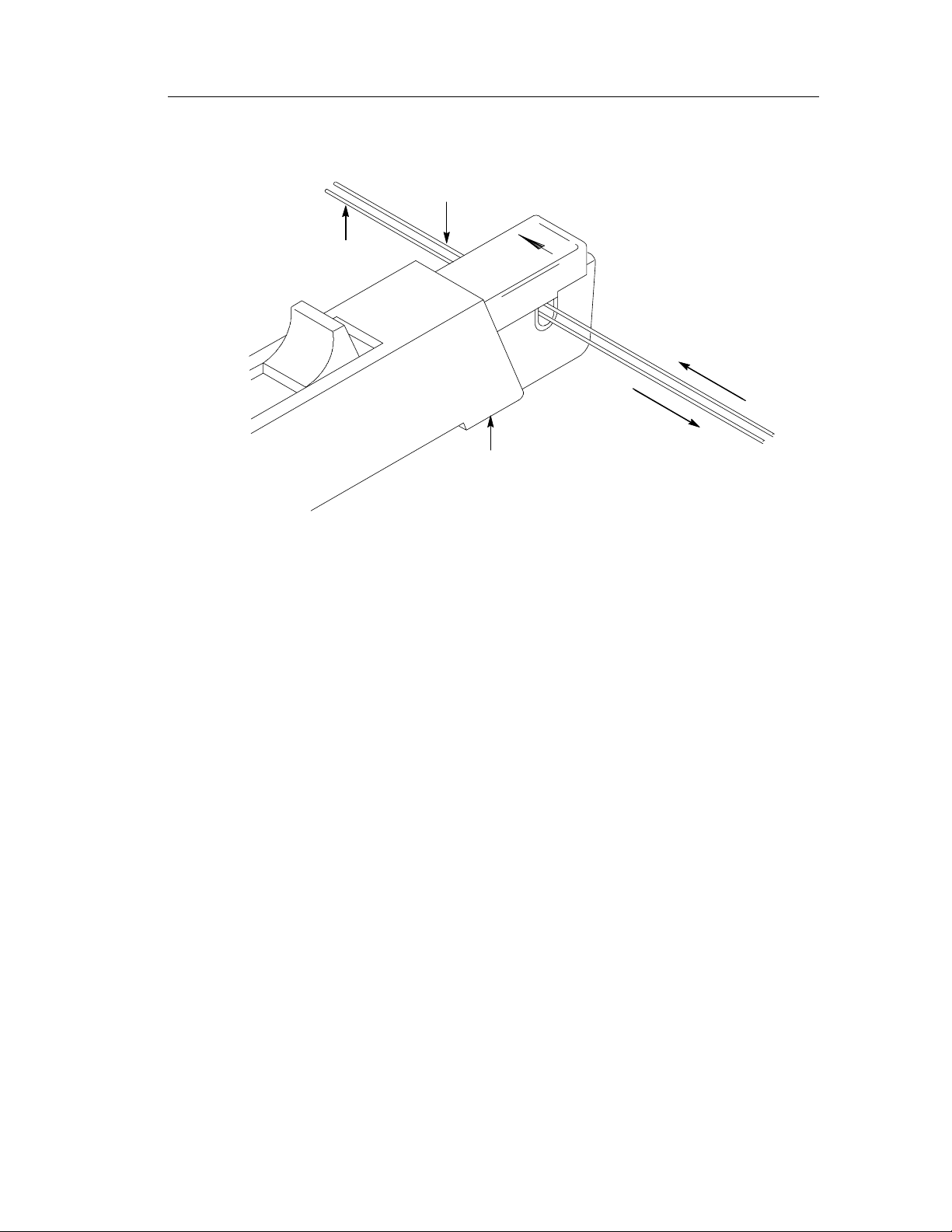
1. Remove the two screws from the bottom of the probe and pull the
strain relief boot back as shown in Figure 25.
34
TCP202 Instruction Manual
Page 45
Strain relief boot
Maintenance
Probe body
Screws
Figure 25: Removing the Strain Relief Boot
2. Move the probe slide assembly to the open position.
NOTE. The probe slide contains a tiny metal ball. In step 3, be careful
not to lose the ball by accidentally letting it fall out.
3. Hold the probe in a top-up horizontal position and slide the top
half of the probe body off as shown i n Figure 26.
4. Remove the metal ball.
5. Turn the probe upside down, push the slide back slight ly, and
remove the slide (see Figure 27).
TCP202 Instruction Manual
35
Page 46

Maintenance
Be careful to keep
this tiny metal ball
from falling out
(a)
(1) Hold the bottom
half of the probe
body in one hand
(b)
(2) Grasp the top half of
the probe body here
with your other hand
(a) Pivot the back end
up
Figure 26: Removing the Top Half of the Probe
(b)Slidethetopforward
off the end of the bottom
half of the probe body
36
TCP202 Instruction Manual
Page 47

(1) Hold the bottom half of
the probe body in one hand
Maintenance
(a)
(b)
(2) Grasp the top half of the
probe body here with your
other hand
(a) Push the slide back
slightly
(b) Withdraw the slide from
the probe body
Figure 27: Removing the Probe Slide
NOTE. The circuit board may be soldered to a ground post attached
to the body half. If nec essary, carefully desolder the connection
before attempti ng to remove the circuit board.
6. If you want to replace the current transformer, lift the transformer
out of the probe as shown in Figure 28, and pull it out of the
circuit board socket. T he c ircuit board may be removed by lifting
out the strain relief and the ci rcuit board from the body half.
TCP202 Instruction Manual
37
Page 48

Maintenance
Circuit board
Current
transformer
Body half
Figure 28: Removing the Current Transformer
7. Before reassembling the probe, be sure that the gap between the
stationary and moveable core pieces is clean. If necessary, use
isopropyl alcohol or a similar cleaning agent to clean the pieces.
Also, clean the contacts of the slide switch, if necessary. Should
the plastic slide assembly require lubrication, sparingly apply
silicone-based grease to the parts.
Probe reassembly is the reverse of steps 1 through 8.
NOTE. Exercise care when fitting the slide back into the probe body;
aligning the switch contacts can require patience.
Obtaining Replacement Parts
38
Replacement parts may be obtained through your local Tektronix
field office or representative. Refer to Replaceable Parts on page 44
for more information.
TCP202 Instruction Manual
Page 49

Preparation for Shipment
If you must ship your Tektroni x product , pl ease use the original
packaging if possible. If the original packaging is unfit for use or not
available, use t he fol lowing packaging guidelines:
1. Use a corrugated cardboard shipping carton having inside
dimensions at least one inch greater than the probe dimensions.
The box should have a carton test strength of at least 200 pounds.
2. Put the probe into a plastic bag or wrap to protect it from
dampness.
3. Place the probe into the box and stabilize it with light packing
material.
4. Seal the carton with shipping tape.
Maintenance
TCP202 Instruction Manual
39
Page 50

Performance Verification and Adjustment
The procedures in this section allow you to demonstrate that the
TCP202 Current Probe and the optional calibrator meet the specified
levels of performance and to adjust them if necessary.
Test Procedure Conditions
These procedures are valid only under the following conditions:
H The system has been calibrated at an ambient temperature
between +20_ Cand+30_ C
H The system is operating in an environment whose limits are
describedinTable1onpage21
H The system, including probe, has had a warm-up period of at
least 20 minutes
H The probe degauss and balance routine has been performed after
the 20-minute warm-up period
Equipment Required
The following procedure verifies the warranted electrical characteristics of the TCP202 Current Probe. Table 5 itemizes the equipment
required, provides an example or part number of the e quipment, and
explains the purpose of the equipment.
NOTE. These procedures assume that you are using an oscilloscope
that automatically displays the correct amperes/division. If not, you
must take the scale factor of the probe into account when setting the
volts/division on the oscilloscope. See page 3 for more information.
40
TCP202 Instruction Manual
Page 51

Table 5: List of Equipment Required
Performance Verification and Adjustments
Minimum
Description
Test oscilloscope Bandwidth: ≥ 200 MHz
Calibration
generator
BNC adapter BNC-female-to-dual
Current loop,
50 Ω
Current loop, 0 Ω
Precision
ohmmeter
Requirements
TekProbe interface
vertical accuracy:
≤ 1.5%
Amplitude accuracy:
≤ 0.25%
Rise time: ≤ 3ns
banana
50 Ω± 0.5%,
BNC male
18 AWG insulated wire,
8 cm (3 in) long
0.02% accuracy with
sense inputs
(4 terminals)
Example or
Part Number
TDS 520B Display probe output
Wavetek 9100
with oscilloscope
option
103-0090-00 Interconnection, current
015-0601-50 or
067-0559-00
— DC Accuracy check
Fluke 8840A Check and adjust input
Purpose
Check probe
DC accuracy, bandwidth, and rise time
loop and generator
Bandwidth and rise
time checks
resistance of optional
calibrator
DC Accuracy
1. Connect a zero-ohm current loop to the output connectors of the
calibration generator.
2. Set the calibration generator for a 1 A, DC output.
3. Set the amperes/division on the oscilloscope to 0.2 A with the
display at a zero reference point at least two divisions be low
center screen.
4. Clamp the jaw of the probe head around the current loop.
5. Check that the DC accuracy is ± 3% (4.85 to 5.15 divisions).
6. Disconnect the setup.
TCP202 Instruction Manual
41
Page 52

Performance Verification and Adjustments
For higher accuracy, refer to page 4 and perform the probe
compensation routine using the optional calibrator, then verify that
the DC accuracy is ± 1% (4.95 to 5.05 divisions).
NOTE. For the compensation routine to work properly, the DC
accuracy of the probe must be at least ± 2% before you begin. If the
probe fails the compensation routine, refer to page 29 f or information
on cleaning the probe head and page 32 for information on accessing
the gain adjustment.
Bandwidth
1. Connect a 50 Ω current loop to the output connector of the
2. Clamp the jaw of the current probe around the current loop.
3. Set the amperes/division on the oscilloscope to 10 mA and
4. Set the calibration generator to 50 kHz and the amplitude to
5. Set the generator to 50 MHz and the oscilloscope to 5 ns/division.
6. Check for ≥ 4.2 divisions peak to peak.
7. Disconnect the setup.
Rise Time
1. Connect a 50 Ω current loop to the 50 Ω fast-rise output of the
calibration generator.
time/division to 20 s. (If you are using a digitizing oscilloscope,
set the acquisition mode to Average and the number of samples
to 16.)
display 6 divisions on screen.
calibration generator.
42
2. Clamp the jaw of the current probe around the current loop.
TCP202 Instruction Manual
Page 53

Performance Verification and Adjustments
3. Set the amperes/division on the oscilloscope to 10 mA and
time/division to 5 ns. (If you are using a digitizing oscilloscope,
set the acquisition mode to Average and the number of samples
to 16.)
4. Set the fast-rise amplitude to display 2 divisions on screen.
5. Check that the rise time is ≤ 7ns.
6. Disconnect the setup.
Calibrator Accuracy (Optional)
1. Connect the sense and input probe tips of the precision ohmmeter
across the two input terminals of the calibrator. (The probe tips of
the sense leads and input leads must contact at the same two
points.)
2. Check that the input resistance of the calibrator measures 42.00
ohms.
3. If the reading is not exact, insert a flat-blade adjustment tool into
the hole in the left side of the calibrator and adjust the resistance
to a value of 42.00 ohms.
4. Disconnect the setup.
TCP202 Instruction Manual
43
Page 54

Replaceable Parts
This section contains a list of the replaceable modules for the
TCP202 Current Probe. Use this list to identify and order replacement parts.
Parts Ordering Information
Replacement parts are available through your local Tektronix field
office or representative.
Changes to Tektronix instruments are sometimes made to accommodate improved components as they become available and to give you
the benefit of the latest circuit improvements. Therefore, when
ordering parts, it is important to include the following information in
your order:
H Part number
H Instrument type or model number
H Instrument serial number
H Instrument modification number, if applicable
If you order a part that has been replaced with a different or
improved part, your local Tektronix field office or representative will
contact you concerning any change in part number.
Change information, if any, is located at the rear of this manual.
Using the Replaceable Parts List
This section contains a list of the mechanical and/or electrical
components that are replaceable for the TCP202 Current Probe. Use
this list to identify and order replacement parts. Table 6 describes
each column in the parts list.
44
TCP202 Instruction Manual
Page 55

Table 6: Parts List Column Descriptions
Replaceable Parts
Column
1 Figure & Index Number Items in this section are referenced by figure and
2 Tektronix Part Number Use this part number when ordering replacement
3 and 4 Serial Number Column three indicates the serial number at
5 Qty This indicates the quantity of parts used.
6 Name & Description An item name is separated from the description
7 Mfr. Code This indicates the code of the actual manufacturer
Column Name Description
index numbers to the exploded view illustrations
that follow.
parts from Tektronix.
which the part was first effective. Column four
indicates the serial number at which the part was
discontinued. No entries indicates the part is good
for all serial numbers.
by a colon (:). Because of space limitations, an
item name may sometimes appear as incomplete.
Use the U.S. Federal Catalog handbook H6-1 for
further item name identification.
of the part.
8 Mfr. Part Number This indicates the actual manufacturer or vendor
part number.
Abbreviations
Abbreviations conform to American National Standard ANSI
Y1.1--1972.
Mfr. Code to Manufacturer Cross Index
The table titled Manufacturers Cross Index shows codes, names, and
addresses of manufac turers or vendors of components listed in the
parts list.
TCP202 Instruction Manual
45
Page 56

Replaceable Parts
11
12
10
1
2
4
9
6
8
7
3
5
Figure 29: TCP202 and Replaceable Accessories
46
TCP202 Instruction Manual
Page 57

Replaceable Parts
DESCRIPTION
80009 650--3463--00
CIRCUIT BOARD
DESCRIPTION
3M099 ORDER BY
BT,PANHEAD,STEEL,CADIUM PLATED,POZIDRIVE
DESCRIPTION
Qty Name & Description Mfr. Code Mfr. Part Number
Serial No.
Discont’d
Serial No.
Effective
Tektronix
Part Number
--1 204-- 0288--03 1 BODY HALF,PROBE:UPPER 80009 204--0288--03
TCP202 Replaceable Parts and Accessories
Fig. &
Index
Number
29-- 1 PROBE, CURRENT: TCP202
--2 214-- 0835--00 1 SPRING,HLCPS:0.127 OD X 2.65 L,SST 91260 ORDER BY
TCP202 Instruction Manual
--3 214--0849--00 1 RTNR RETURN SPR:BRS CD PL 80009 214-- 0849--00
--4 352--0106--00 1 HOLDER,SPR RTNR:DELRIN TK2565 352--0106--00
--5 650-- 3463--00 1 BD/CABLE ASSY:CABLE W/TCP202 PROBE
--6 213--0087--00 2 SCREW,TPG,TC:2--32 X 0.5,TYPE
--7 334-- 9171--00 1 MARKER, ID:PROBE ID,TCP202 0KB05 334--9171-- 00
--8 204--0714--06 1 BODY,HALF:LOWER BODY HALF W/CONTACTS 80009 204-- 0714--06
--9 120-- 1984--00 1 XFMR SUBASSY:UPPER & LOWER TRANSFORMER 80009 120--1984--00
--10 214--0854--00 1 CONTACT,ELEC:UPPER SHELF,CU BE TK1947 214--0854--00
--11 351--0121--01 1 CONT ASSY,ELEC:PROBE SLIDE ASSY 80009 351--0121--01
070--9542--XX 1 MANUAL,TECH:INSTRUCTIONS,TCP202 TK2548 070--9542-- XX
070--9543--XX 1 MANUAL,TECH:REFERENCE,TCP202 TK2548 070--9543--XX
--12 214--0997--00 1 BALL,BEARING:0.094,SST 05469 ORDER BY
47
Page 58

Replaceable Parts
NOTE: Parts illustrated
with dashed lines are not
replaceable
6
5
4
3
2
1
7
Qty Name & Description Mfr. Code Mfr. Part Number
Serial No.
Discont’d
Serial No.
Effective
Tektronix
Figure 30: Replaceable Parts - Compensation Box
Part Number
--2 131--3627--01 1 CONTACT,ELEC:GOLD PLATED TIP 18359 P-- 6158-- 1
Replaceable Parts - Compensation Box
Fig. &
Index
Number
30--1 205-- 0191-- 00 1 SHELL,ELEC CONN:BNC,ABS,DOVE GRAY 80009 205-- 0191-- 00
--3 206--0429--06 1 COMP BOX HALF:TOP TK2565 206-- 0429--06
48 TCP202 Instruction Manual
Page 59

Replaceable Parts
Mfr. Part NumberMfr. CodeName & DescriptionQty
0KB05 334--9139-- 00
LABEL,TCP202
80009 348--1487--00
FOAM,0.005 THK ACRYLIC ADHESIVE,1 SIDE,0.850
X0
0KB05 334--9140-- 00
LEXAN,POLY,TCP202,
Serial No.
Discont’d
Serial No.
Effective
Tektronix
Part Number
Number
--4 334-- 9139--00 1 MARKER,IDENT:FRONT IDENTIFICATION
Fig. &
Replaceable Parts - Compensation Box (Cont.)
Index
--5 348-- 1487--00 2 CUSHION:FOAM CUSHION,30 PPI POLY FILTER
TCP202 Instruction Manual
--6 206--0430--00 1 COMP BOX:COVER,BOTTOM HALF 80009 206--0430--00
--7 334--9140--00 1 MARKER,IDENT:BACK IDENTI FICATION LABEL,GE
49
Page 60

Replaceable Parts
80009 015--0672--50
2
50 OHM
Qty Name & Description Mfr. Code Mfr. Part Number
Serial No.
Discont’d
Serial No.
Effective
1
Tektronix
Figure 31: TCP202 Optional Accessories
Optional Accessories
Part Number
Fig. &
Index
Number
31--1 003-- 1383-- 00 1 RLSE TOOL,COVER:COMP BOX,POLYCARBONATE TK2565 003--1383--00
--2 015--0672--50 1 ADAPTER,CALIBRATOR: 50 TURN CURRENT LOOP,
1103 1 TEKPROBE IF PS:W/OFFSET 2 CONN 80009 1103
50 TCP202 Instruction Manual
Page 61

CLEVELAND, OH 44101
BEAVERTON, OR 97077-- 0001
TACOMA, WA 98411-- 0610
Replaceable Parts
BEAVERTON, OR 97005
Manufacturers Cr oss Index
Mfr.
Manufacturer Address City, State, Zip Code
Code
05469 BEARINGS INC 3634 EUCLID
PO BOX 6925
0KB05 NORTH STAR NAMEPLATE INC 5750 NE MOORE COURT HILLSBORO, OR 97124--6474
18359 PYLON CO. INC. 51 NEWCOMB ST ATTLEBORO, MA 02703--1403
3M099 PORTLAND SCR EW COMPANY 6520 N BASIN AVE PORTLAND, OR 97217
PO BOX 110610
PO BOX 500
80009 TEKTRONIX INC 14150 SW KARL BRAUN DR
TK1947 NORTHWEST ETCH TECHNOLOGY 2601 S HOOD ST
91260 CONNOR FORMED METAL PRODUCTS 1729 JUNCTION AVENUE SAN JOSE, CA 95112
14181 SW MILLIKAN WAY
TK2548 XEROX CORPORATION DIV OF XEROX CORPORATION
TK2565 VISION PLASTICS INC 26000 SW PARKWAY CENTER DRIVE WILSONVILLE, OR 97070
TCP202 Instruction Manual
51
Page 62

Replaceable Parts
52 TCP202 Instruction Manual
 Loading...