


TCP0150
20 MHz, 150 A AC/DC Current Probe
Instruction Manual
www.tektronix.com
071-2251-00

Copyright © Tektronix. All rights reserved. Licensed software products are owned by Tektronix or its subsidiaries or suppliers, an d are protected by
national copyright laws and international treaty provisions.
Tektronix products are covered by U.S. and foreign patents, issued and pending. Information in this publication supersedes that in all previously
published material. Specifications and price change privileges reserved.
TEKTRONIX and TEK are registered trademarks of Tektronix, Inc.
Contacting Tektronix
Tektronix, Inc.
14200 SW Karl Braun Drive
P.O . Bo x 5 0 0
Beaverton, OR 97077
USA
For product information, sales, service, and technical support:
In North America, call 1-800-833-9200.
Worldwide, visit www.tektronix.com to find contacts in your area.

Warranty 2
Tektronix warrants that th is product will be free from defects in materials and workmanship for a period of one (1) year from the date of shipment. If
any such product proves defective during this warranty period, Tektronix, at its option, either will repair the defective product without charge for parts
and labor, or will provide a replacement in exchange for the defective product. Parts, modules and replacement products used by Tektronix for
warranty work may be new or reconditioned to like new performance. All replaced parts, modules and products become the property of Tektronix.
In order t o obtain service under this warranty, Customer must notify Tektronix of the defect before the expiration of the warranty period and make
suitable arrangements for the performance of service. Customer shall be responsible for packaging and shipping the defective product to the service
center designated by Tektronix, with shipping charges prepaid. Tektronix shall pay for the return of the product to Customer if the shipment is to a
location within the country in wh ich t he Tektronix service center is located. Customer shall be responsible for paying all shipping charges, duties,
taxes, and any other charges for products returned t o any other locations.
This warranty s hall not apply to any defect, failure or damage caus ed by improper use or improper or inadequate maintenance and c are. Tektronix
shall not be obligated to furnish service under this warranty a) to repair damage resulting from attempts by personnel other than Tektronix
representatives to install, repair or service the product; b) to repair damage resulting from improper use or connection to incompatible equipment; c) to
repair any damage or malfunction caused by the use of non-Tektronix supplies; or d) to service a product that has been modified or integrated with
other products when the effect of such modification or integration increases the time or difficulty of servicing the product.
THIS WARRANTY IS GIVEN BY TEKTRONIX WITH RESPECT TO THE PRODUCT IN LIEU OF ANY OTHER WARRANTIES, EXPRESS OR
IMPLIED. TEKTRONIX AND ITS VENDORS DISCLAIM ANY IMPLIED WARRANTIES OF MERCHANTABILITY OR FITNESS FOR A PARTICULAR
PURPOSE. TEKTRONIX’ RESPONSIBILITY TO REPAIR OR REPLACE DEFECTIVE PRODUCTS IS THE SOLE AND EXCLUSIVE REMEDY
PROVIDED TO THE CUSTOMER FOR BREACH OF THIS WARRANTY. TEKTRONIX AND ITS VENDORS WILL NOT BE LIABLE FOR ANY
INDIRECT, SPECIAL, INCIDENTAL, OR C ONSEQUENTIAL DAMAGES IRRESPECTIVE OF WHETHER TEKTRONIX OR THE VENDOR HAS
ADVANCE NOTICE OF THE POSSIBILITY OF SUCH DAMAGES.


Table of Contents
General Safety Sum m ary . . ................................................................................................................. v
Service Safety Summary .................................................................................................................. viii
Environmental Considerations ............................................................................................................. ix
Preface...................................................................................................................................... xi
Documentation........................................................................................................................ xi
Conventions Used in this Manual .................................................................................................... xi
Returning the Probe for Servicing ...................................................................................................xii
Key Features ............................................................................................................................... 1
Installation .................................................................................................................................. 2
Using the Probe Head ................................................................................................................ 3
Degaussing the Probe................................................................................................................ 4
Connecting to the Circuit .. ........................................................................................................... 6
Probe Controls and Indicators ........................................................................................................ 8
Functional Check andBasic Operation ................................................................................................... 16
Basic Operation...................................................................................................................... 17
Application Examples...................................................................................................................... 18
Inductance M easurements .......................................................................................................... 19
Measuring Inductor Turns Count .................................................................................................... 22
Table of Contents
TCP0150 Current Probe Instruction Manual i

Table of Contents
Accessories and Options.................................................................................................................. 24
Probing Principles ......................................................................................................................... 30
Specifications.............................................................................................................................. 43
User Maintenance ......................................................................................................................... 55
Performance Verification .................................................................................................................. 57
Standard Accesso ries ............................................................................................................... 24
Optional Accessories ................................................................................................................ 26
Options ............................................................................................................................... 29
Degaussing a Probe with an Unpowered Conductor in the Jaws .. ................................................................ 30
Measuring Differential Current....................................................................................................... 31
Extending Current Range............................................................................................................ 33
Increasing Sensitivity ................................................................................................................ 36
Common Mode Noise/Magnetic Field Errors........................................................................................ 37
AC and DC Coupling.................................................................................................................38
Maximum Current Limits............................................................................................................. 39
Warranted Characteristics ........................................................................................................... 44
Typical Characteristics............................................................................................................... 45
Nominal Characteristics ............................................................................................................. 51
Certifications and Compliances ..................................................................................................... 51
Oscilloscope Firmware .............................................................................................................. 55
Troubleshooting...................................................................................................................... 55
Cleaning.............................................................................................................................. 56
Equipment Required................................................................................................................. 58
ii TCP0150 Current Probe Instruction Manual

Table of Contents
Making the DC Current Loop ........................................................................................................ 59
Equipment Setup..................................................................................................................... 60
DC Gain Accuracy ................................................................................................................... 61
Rise Time and Bandwidth ........................................................................................................... 64
TestRecord .......................................................................................................................... 66
Adjustments................................................................................................................................ 67
Equipment Required................................................................................................................. 67
Equipment Setup..................................................................................................................... 67
DC Gain Accuracy ................................................................................................................... 68
Repair...................................................................................................................................... 70
Repairing the Probe ................................................................................................................. 70
Probe Disassembly .................................................................................................................. 71
Reassembly.......................................................................................................................... 79
Replaceable Parts ................................................................................................................... 80
Index
TCP0150 Current Probe Instruction Manual iii

Table of Contents
iv TCP0150 Current Probe Instruction Manual

General Safety Summary
Review the following safety precautions to avoid injury and prevent damage to this product or any products con nected to it.
To avoid potential hazards, use this product only as sp ecified.
Only qualified personnel should pe rform service procedures.
To Avoid Fire or Personal Injury
Connect and Disconnect Properly. Do not connect or disconnect probes or test leads while they are connected to a voltage
source.
Connect and Disconnect Properly. De-energize the circuit under test before connecting or disconnecting the current probe.
Connect and Disconnect Properly. Connect the probe output to the measurement instrument before connecting the probe to the
circuit under test. Connect the probe reference lead to the circuit under test before connecting the p robe input. Disconnect the probe
input and the probe reference lead from the circuit under test before disconnecting the probe from the measurement instrument.
Ground the Product. This product is indirectly grounded through the grounding conductor of the mainframe power cord. To avoid
electric shock, the grounding conductor must be connected to earth ground. Before making connections to the input or o utput
terminals of the product, ensure that the product is properly grounded.
Observe All Terminal Ratings. To avoid fire or shock hazard, observe all ratings and markings on the product. Consult the
product manual for further ratings information before making connections to the product.
Do not apply a potential to any terminal, including the common terminal, that exceeds the maximum rating of that terminal.
General Safety Summary
Do not co nnect a current probe to any wire that carries voltages above the current probe voltage rating.
Do Not Operate Without Covers. Do not operate this product with covers or panels removed.
TCP0150 Current Probe Instruction Manual v
General Safety Summary
Do Not Operate With Suspected Failures. If you suspect that there is damage to this product, have it inspected by qualified
service personnel.
Avoid Exposed Circuitry. Do not touch exposed connections and components when power is present.
Do Not Operate in Wet/Damp Conditions.
Do Not Operate in an Explosive Atmosphere.
Keep Product Surfaces Clean and Dry.
Provide Proper Ventilation.
ventilation.
Refer to the manual’s installation instructions for details on installing the product so it has proper
TermsinthisManual
These terms may appear in this manual:
WARNING. Warning statements identify conditions or practices that could result in injury or loss of life.
CAUTION. Caution statements identify conditions or practices that could result in damage to this product or other property.
vi TCP0150 Cu rrent Probe Instruction Manual
Symbols and Terms on the Product
These terms may appear on the product:
DANGER indicates an injury hazard immediately accessible as you read the marking.
WARNING indicates an injury hazard not immediately accessible as you read the marking.
CAUTION indicates a hazard to property including the product.
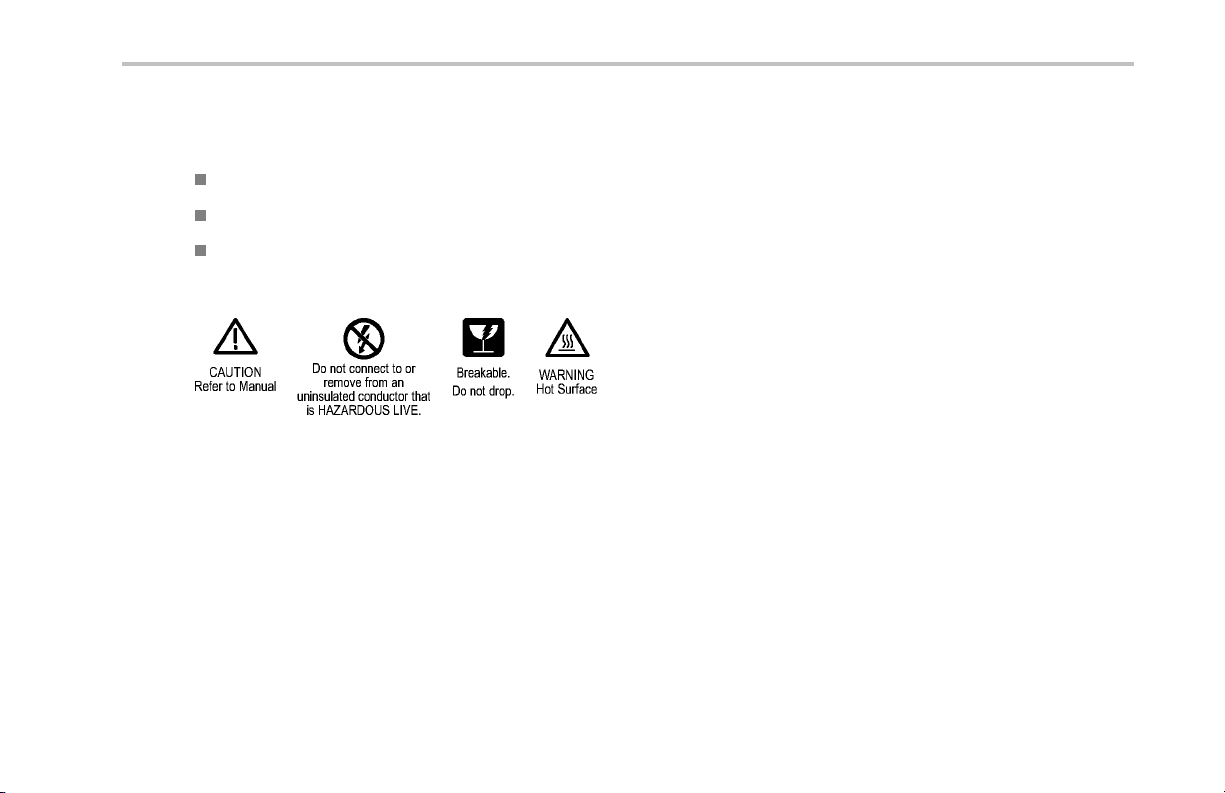
The following symbol(s) may appear on the product:
General Safety Summary
TCP0150 Current Probe Instruction Manual vii

Service Safety Summary
Service Safety Summary
Only qualified personnel should perform service procedures. Read this Service Safety Summary and the General Safety Summary
before performing any service procedures.
Do Not Service Alone. Do not perform internal service o r adjustments of this product unless another person capab le of
rendering first aid and resuscitation is present.
Disconnect Power. To avoid electric shock, switch off the instrume nt power, then disconnect the power cord from the mains
power.
Use Care When Servicing With Power On. Dangerous voltages or currents may exist in this product. Disconnect power,
remove battery (if applicable), and disconnect test leads before removing protective panels, soldering, or replacing components.
To avoid electric shock, do not touch exposed connections.
viii TCP0150 Current Probe Instruction Manual

Environmental Considerations
This section provides information about the environmental impact of the product.
Product End-of-Life Handling
Observe the following guidelines when recycling an instrument or component:
Equipment Recycling. Production of this equipment required the extraction and use of natural resources. The equipment may
contain substances that could be harmful to the environment or human health if improperly handled at the product’s end of life. In
order to avoid release of such substances into the environment and to reduce the use of natural resources, we encourage you to
recycle this product in an appropriate system that will ensure that most of the materials are reused or recycled appropriately.
The symbol shown below indicates that this product complies with the European Union’s requirements according to Directive
2002/96/EC on w aste electrical and electronic equipment (WEEE). For information about recycling options, check the
Support/Service section of the Tektronix Web site (www.tektronix.com).
Environmental Considerations
TCP0150 Current Probe Instruction Manual ix

Environmental Considerations
Restriction of Hazardous Substances
This product has been classified as Monitoring and Control equipment, and is outside the scope of the 2002/95/EC RoHS Directive.
This product complies with the RoHS Directive requirements except for the presence of hexavalent chromium in the surface coating
of the aluminum chassis parts, assembly hardware, and 63/37 tin/lead solder used in the fabrication of th e circuit boards.
x TCP0150 Current Probe Instruction Manual
Preface
This manual describes the installation and operation of the TCP0150 current probe. Basic probe operations and concepts are
presented in this manual. You can also access the Tektronix Web site for this document and other related information.
Documentation
Preface
To read about Use these documents
TCP0150 Probe: First Time Operation, Functional Check,
Operating Basics, Specifications, Performance Verification
In-depth oscilloscope operation, user interface help, GPIB
commands
*
To access the documentation that is installed on your instrument, click Start in the taskbar and select Programs > TekApplications.
Read this Instruction Manual.
Access the online help from the Help menu on the host
instrument.
*
Conventions Used in this Manual
The following icon is used throughout this manual to indicate a step sequence.
TCP0150 Current Probe Instruction Manual xi
Preface
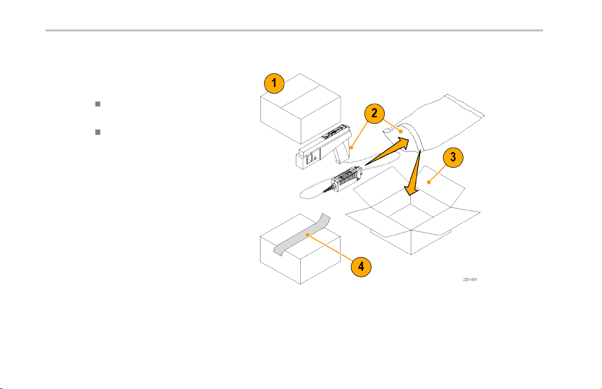
Returning the Probe for Servicing
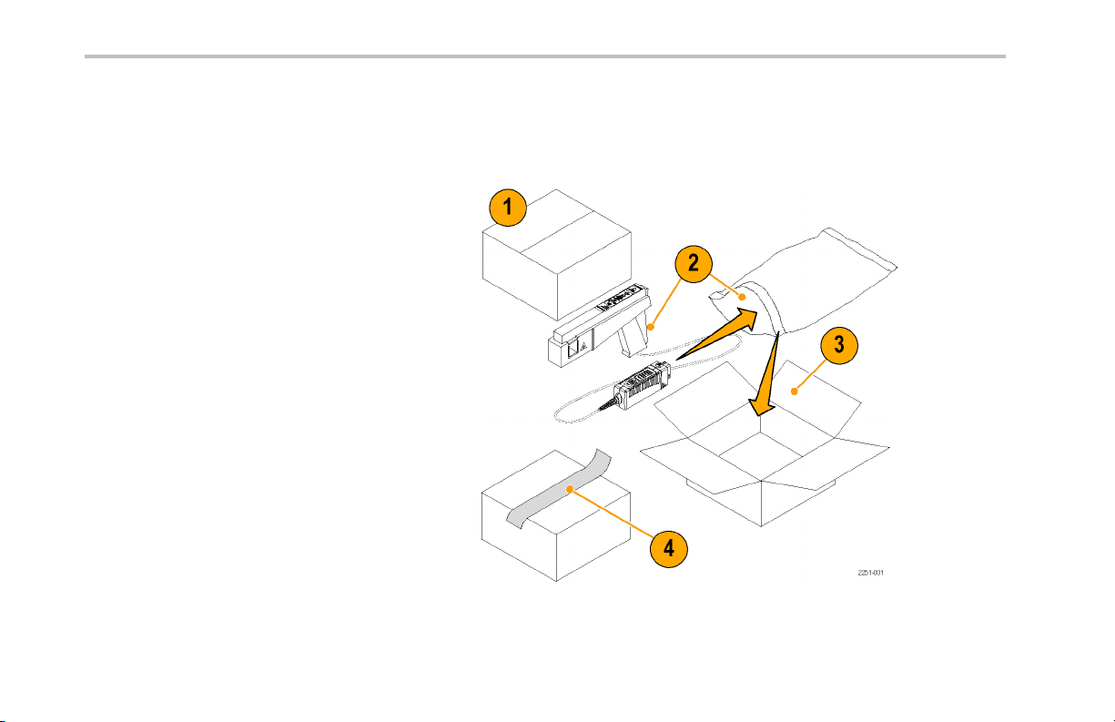
If your probe requires servicing, you must return the probe to Tektronix. If the o riginal packaging is unfit for u s e or not available, use
the following packaging guidelines:
Preparation for Shipment
1. Use a corrugated cardboard shipping
carton having inside dimensions at
least one inch greater than the p robe
dimensions. The box should have a carton
test strength of at least 200 pounds.
2. Put the probe into an antistatic bag or wrap
it to protect it from dampness.
3. Place the probe into the box and stabilize it
with light packing material.
4. Seal the carton with shipping tape.
5. Refer to Contacting Tektronix at the
beginning of this manual for the shipping
address.
xii TCP0150 Current Probe Instruction Manual
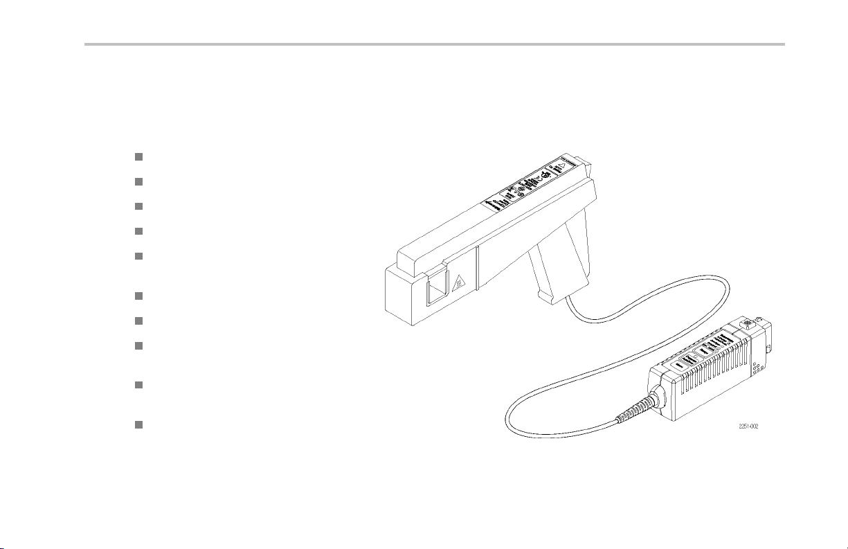
Key Features
You can use the TCP0150 current probe to make accurate measurements from D C to 20 MHz. The probe combines proven
Hall-effect te chnology with the Tektronix TekVPI oscilloscope interface. Key features include:
>20 M Hz bandwidth, <17.5 ns rise time
AC/DC Measurement capability
500 A peak pulse current (PW <30 μs)
25 A and 150 A range settings
5 mA sensitivity ( on TekVPI oscilloscopes
that support the 1 mV/div setting)
1% DC Accuracy (typical)
One-button degauss/autozeroing
Probe control through the oscilloscope
menus or remotely through the oscilloscope
Direct scaling and unit readout on host
instruments
AC coupling (oscilloscope dependent)
Key Features
TCP0150 Current Probe Instruction Manual 1
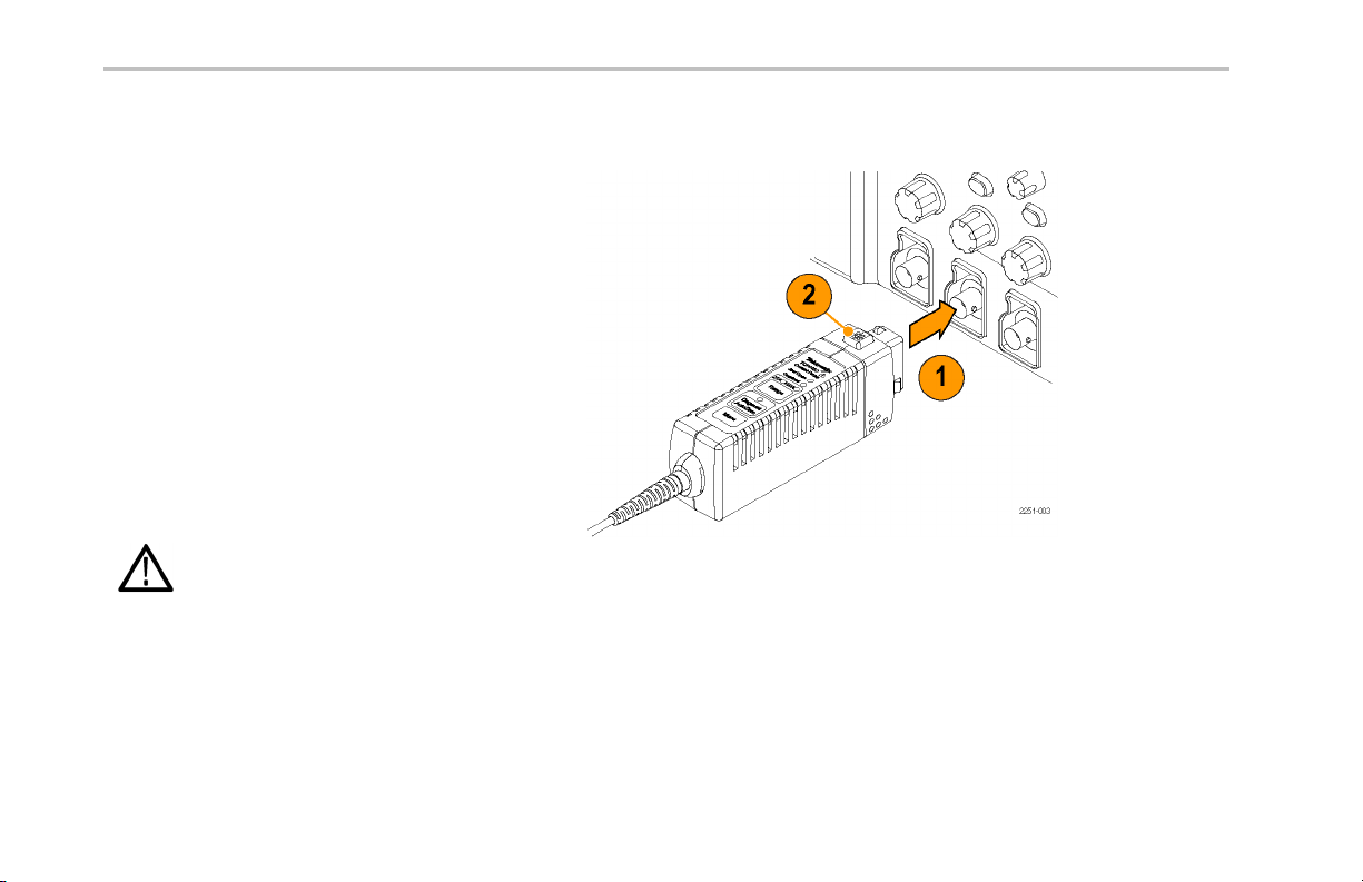
Installation
Installation
1. Slide the probe into the TekVPI receptacle.
The probe snaps in when fully engaged.
When the probe is connected, the host
instrument reads information from the
probe and identifies the device. All of the
probe LEDs light briefly for a quick visual
check.
2. To disconnect, press the latch button and
pull the probe away from the instrument.
NOTE. Your TekVPI instrument may require a
firmware upgrade to support full functiona lity
of the probe.(See page 55, Oscilloscope
Firmware.)
CAUTION. To preven t the compe nsation box
from overheating, ensure that all ventilation
openings are unobstructed whe n connected to
the oscilloscope.
2 TCP0150 Current Probe Instruction Manual
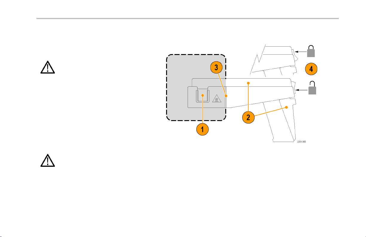
Using the Probe Head
1. The U-shaped current-sensing core (the
jaw) is located at the front of the probe.
CAUTION. To prevent risk of fire, do not
connect or disconnect the current probe to or
from a live, uninsulated conductor. The core
is not insulated. When you test un insulated
circuits, remove power before you connect or
disconnect the probe.
2. The trigger at the rear of the probe opens
and closes the sliding bar over the jaw and
the conductor under test.
3. Keep your hands b ehind the tactile barrier
(away from the shaded area) when
connected to live circuitry.
WARNING. To prevent risk of electric shock,
keep your hands behind the tactile barrier
which indicates the limit of safe access.
4. Press the lock switch up to lock the slide
and down to unlock it.
Installation
TCP0150 Current Probe Instruction Manual 3
Installation
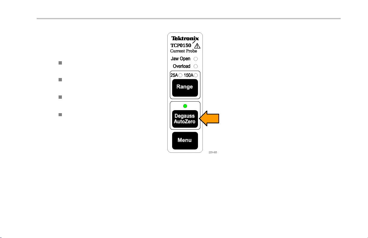
Degaussing the Probe
1. After the probe is identified by the host
instrument:
The screen display prompts you to
degauss the probe
The multicolor Degauss/AutoZero
status LED on the probe flashes red
NOTE. The DC gain and offset are not
guaranteed when this LED flashes red.
2. With no conductor in the jaw, lock the
probe slide.
3. Press the Degauss/AutoZero button on
the probe or in the Degauss window on the
host instrument.
4. The multicolor Degauss/ AutoZero status
LED glows green to indicate a successful
degauss routine was run, and that the
probe is in normal operating mode.
4 TCP0150 Current Probe Instruction Manual
Quick Tip
To maintain measurement accuracy, degauss
your probe in each of these c ases:
After you turn on the measurement system
and allow a 20-minute warm-up period
Before you connect the probe to a
conductor
Whenever a current or thermal overload
condition occurs
Whenever you subject the probe to a
strong external magnetic field
Installation
TCP0150 Current Probe Instruction Manual 5
Installation
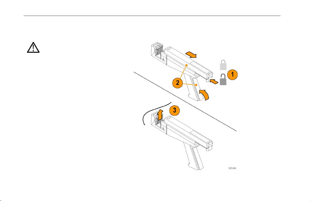
ConnectingtotheCircuit
CAUTION. To avoid damage to the probe
core, do not drop the probe or subject it to
physical shock, strain, or sudden changes in
ambient conditions.
1. Press the lock switch down to unlock the
slide.
2. Squeeze the trigger handle to open the jaw.
3. Place the jaw around the conductor in the
circuit.
6 TCP0150 Current Probe Instruction Manual
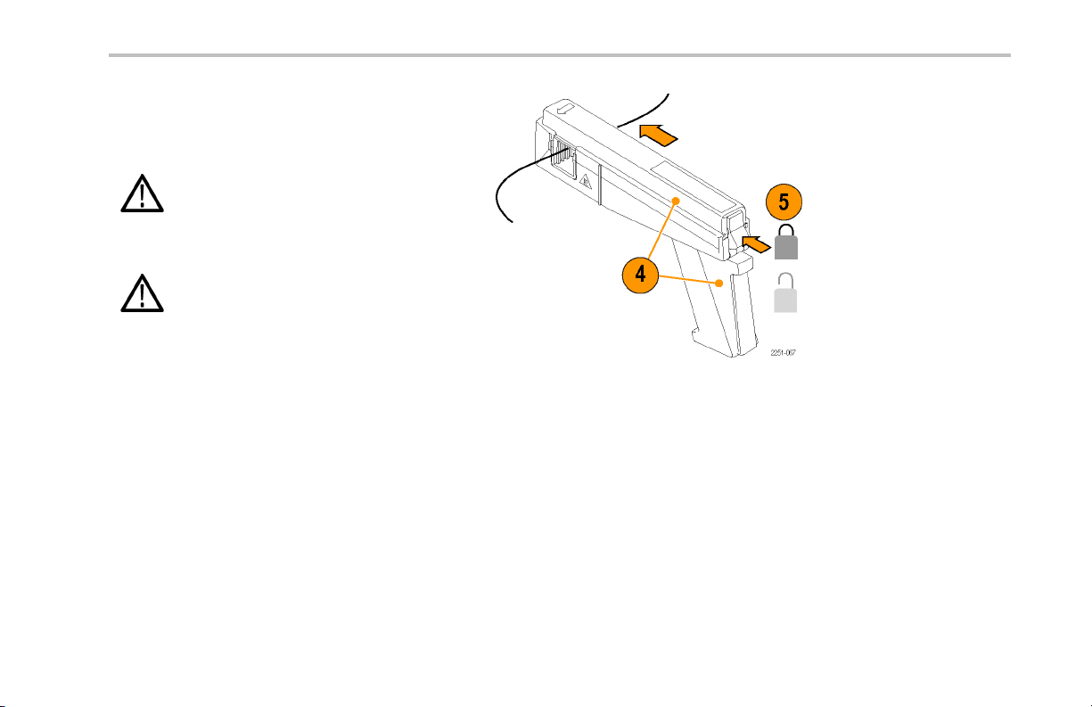
4. Release the trigger to close the slide over
the jaw.
5. Press the lock switch up to lock the slide.
WARNING. To prevent risk of electric shock,
use protective equipment (gloves, for example),
if you use the probe on accessible uninsulated
wires or bus bar.
WARNING. Do not exceed the ba re wire
voltage rating of the probe. R efer to the
specification section for details.
Installation
TCP0150 Current Probe Instruction Manual 7
Installation
Probe Controls and Indicators
When you connect the probe to the
oscilloscope, all of the indicator LEDs light
briefly, and then at least two LEDs remain
lighted to indicate:
The current range selected
The Degauss/AutoZero status
NOTE. On some host instruments, the probe
retains the range state and restores it when it
is power cycled.
8 TCP0150 Current Probe Instruction Manual
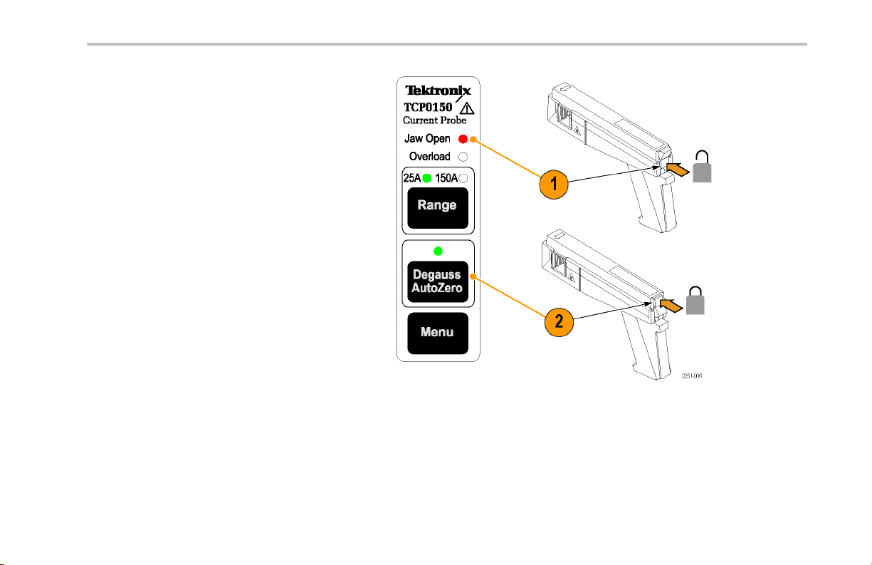
Jaw Open LED
1. If the Jaw Open LED glows, the probe slide
is unlocked.
2. Lock the probe slide to accurately measure
current or to degauss the probe.
Installation
TCP0150 Current Probe Instruction Manual 9
Installation
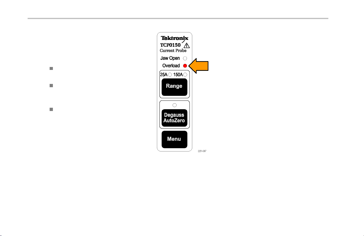
Overload LED
The multicolor Overload LED alerts you that
the probe specifications are being exceeded.
The Overload LED alert conditions are:
Glowing red. The maximum continuous
input current limit has been exceeded
Glowing orange. The safe operating
temperature of the probe has been
exceeded
Flashing red and orange. Both the
maximum continuous input current limit
and the safe operating temperature of the
probe have been exceeded
NOTE. The probe will sh ut down if you exceed
the safe operating temperature. To reset
the probe, disconnect the probe from the
oscilloscope, let it cool, and then reconnect it.
Quick Tip
An input current overload can magnetize the
probe. Always degauss t he probe after an
overload.
10 TCP0150 Current Probe Instruction Manual
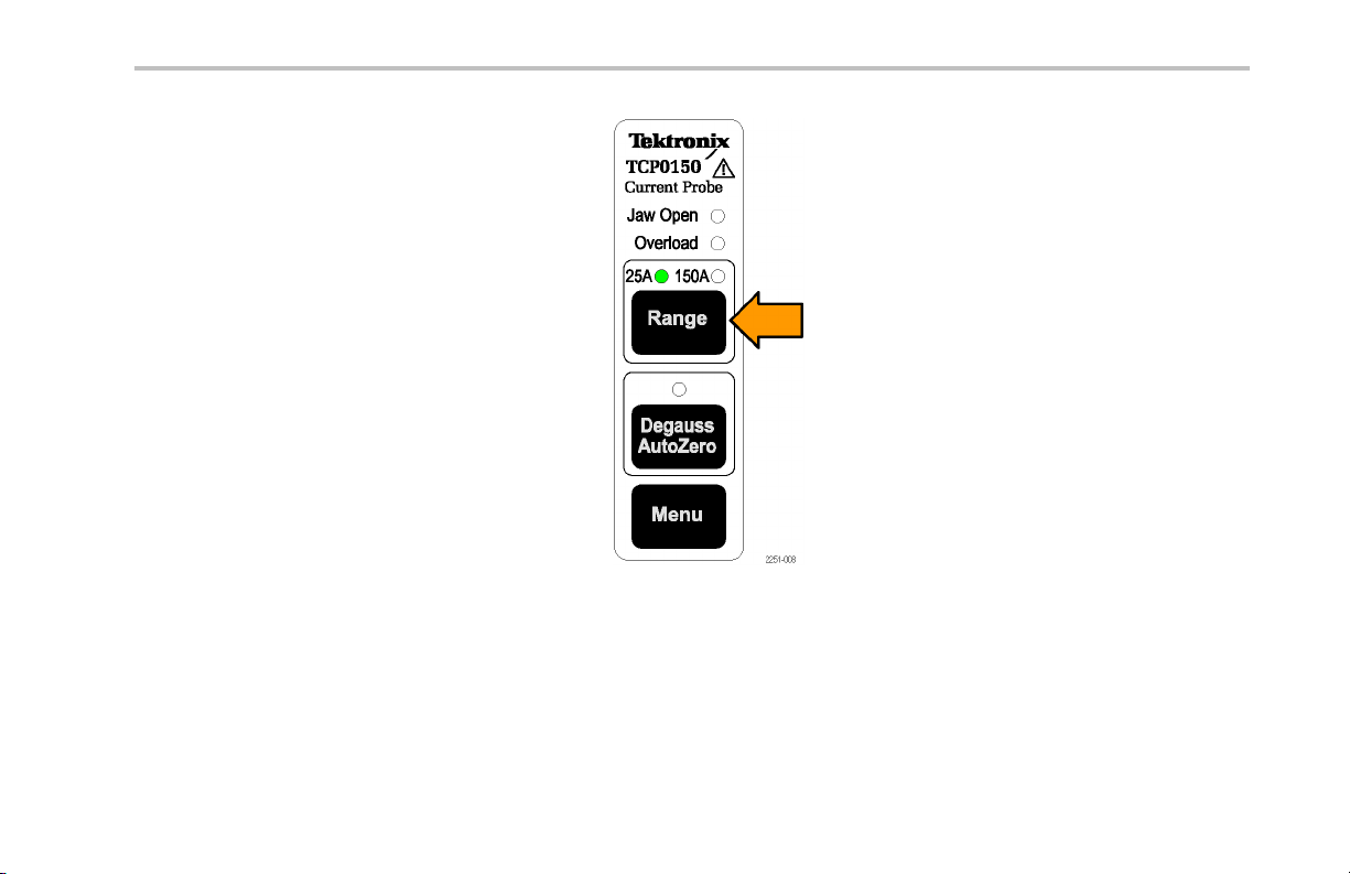
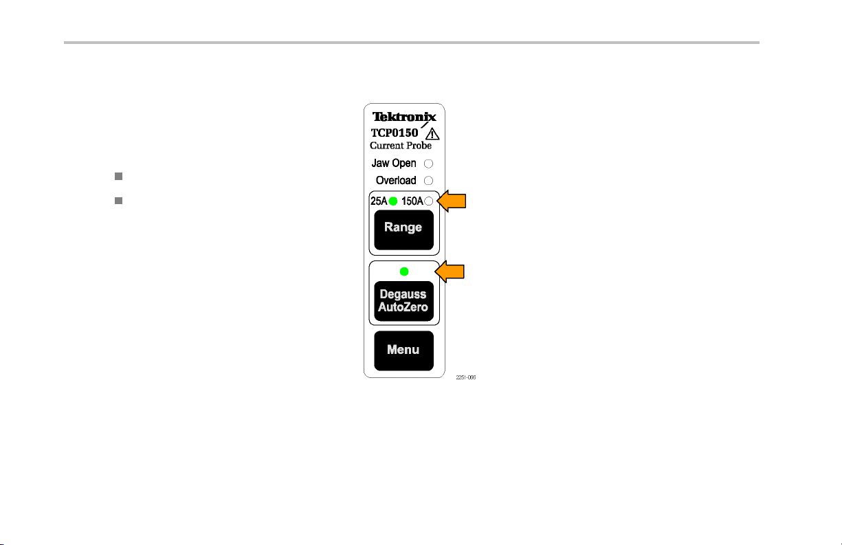
Range Button and LEDs
Press the Range button to select between the
25 A and 150 A current range settings.
The green LEDs indicate the selected range.
The range and units are also displayed on the
oscilloscope screen.
Installation
TCP0150 Current Probe Instruction Manual 11
Installation
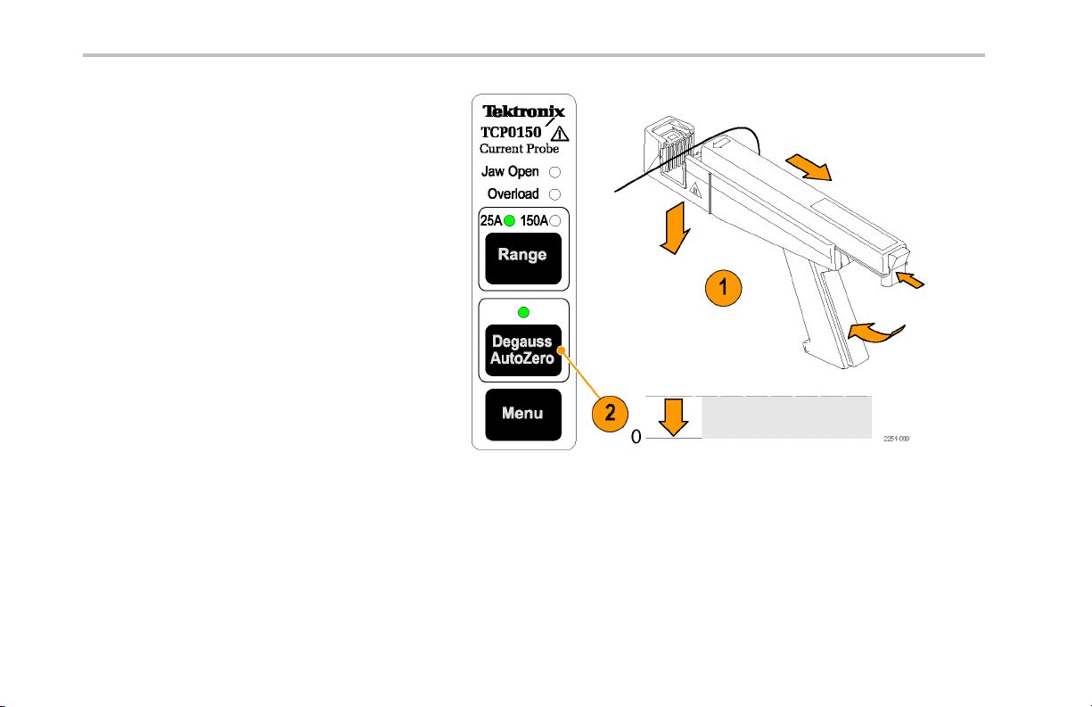
Degauss/AutoZero
Button and LED
When the multicolor Degauss/AutoZero status
LED fl ashes red , you must degauss the probe.
If th e LED flashes orange, you should degauss
the probe. The DC gain and offset accuracy are
not guaranteed when this LED flashes orange.
The Degauss/AutoZero function also clears
(AutoZeroes) any DC offset in the probe.
To degauss the p robe, d o the following:
1. Disconnect the probe from the current
source and lock the slide.
2. Press the Degauss/AutoZero button to
initiate the degauss routine.
The LED glows green a fter successfully
completing t he Degauss/AutoZero routine.
12 TCP0150 Current Probe Instruction Manual
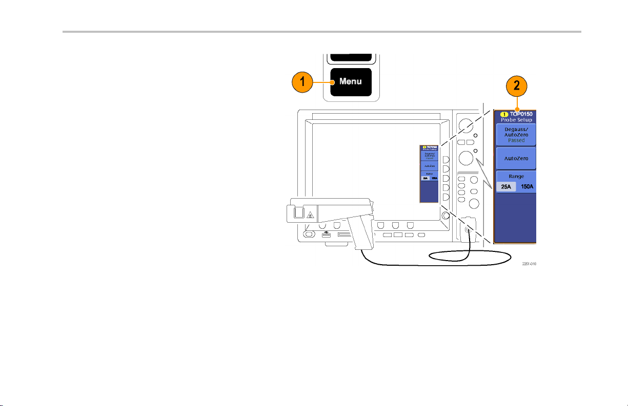
Menu Button
1. Press the Menu button on the probe.
2. The P robe Setup or Probe Controls screen
displays and shows your probe sett ings;
the screen differs by oscilloscope model.
(See page 14, Optional Probe Screens.)
Use the screen buttons to change
the settings or to access other probe
information.
3. Press the Menu button again to close the
screen.
Installation
TCP0150 Current Probe Instruction Manual 13
Installation
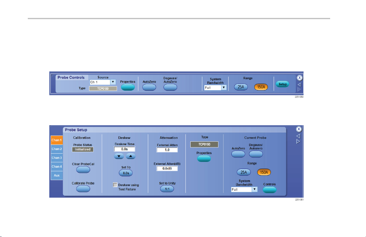
Optional Probe Screens
The following screens may be available for the probe, depending on the host oscilloscope model.
The P robe Controls screen may be accessed from the p robe Menu button or other probe screens. It contains buttons for common
probe functions and for access to other probe screens, such as Probe Setup and Probe Properties.
Click the Setup button to display the Probe Setup screen.
14 TCP0150 Current Probe Instruction Manual

Click the Properties button to display the Probe Properties screen.
Installation
TCP0150 Current Probe Instruction Manual 15

Functional Check and Basic Operation
Functional Check and Basic Operation
The following procedure checks that your probe is functioning properly. To verify that your pro be meets the warranted specifications,
refer to the Performance Verification procedures. (See page 57.)
1. Connect the probe to any channel (1–4) of
the oscilloscope.
2. Press the Degauss/AutoZero button.
3. When the Degauss/AutoZero LED glows
green, connect the probe to your circuit.
4. Set the oscilloscope to display the probe
channel.
5. Adjust the oscilloscope or press Autoset
to display a stable waveform.
A stable waveform indicates that your
probe is functioning correctly.
16 TCP0150 Current Probe Instruction Manual

Basic Operation
1. Check the oscilloscope display before
connecting the probe to a conductor.
If there is a DC offset, degauss the probe.
(See page 4, Degaussing the Probe.)
2. For correct polarity reading, connect the
probe so that the positive-to-negative
current flow is aligned with the arrow on
the probe jaw.
Close and lock the probe jaw over the
conductor.
3. Read the measurement on the oscilloscope
display.
CAUTION. To prevent risk of electric shock or
fire, do not exceed the bare wire voltage rating
of t he probe. (See page 43, Specifications.)
Functional Check and Basic Operation
TCP0150 Current Probe Instruction Manual 17

Application Examples
Application Examples
This section explains ways to use yo ur probe in common troubleshooting tasks and how to extend the use of your measurement
system.
18 TCP0150 Current Probe Instruction Manual

Inductance Measurements
You can use the current probe to measure the inductance of coils that have either a low-impedance or high-impedance pulse
source of a known value.
Low-Impedance Pulse Sources
This figure shows a constant-voltage pulse
generator of extremely low output impedance
connected to an inductor that has low
resistance.
1. Connect the inductor across the output
terminals of the pulse generator.
2. Maintain a constant voltage across the
inductor.
3. Clamp the current probe over one of the
source leads.
NOTE. If the probe impedance is a significant
part of the total circuit inductance, measurement
accuracy will be affected. Refer to the probe
specifications fo r probe insertion impedance.
Application Examples
TCP0150 Current Probe Instruction Manual 19

Application Examples
4. Measure the cu rrent ramp. The inductance
is effectively defined by the slope of the
current ramp shown here.
5. Calculate the inductance using the
following formula:
where:
L is the inductance in henries,
E is the voltage of the pulse generator,
dt is the change in time, and
di is the change in current.
20 TCP0150 Current Probe Instruction Manual

High-Impedance Pulse Sources
If the pulse source has a high er impedance of
known resistance, such that the output voltage
drops as the current increases, the inductance
of a coil can be calculated by the time const ant
of the charge curve.
The current ramp shows how the values for the
inductance formula are obtained.
Use this formula to calculate th e inductance
based on the current measurement:
where:
L is the inductance in henries,
τ is the time required for the current to rise
or fall 63.2% of the total current value, and
R is the source resistance of the pulse
generator.
Application Examples
TCP0150 Current Probe Instruction Manual 21

Application Examples
Measuring Inductor Turns Count
To obtain an approximate turns count of an
inductor, do the following:
1. Connect the inductor to a current limited
source, as shown.
2. Measure the input current on one of the
inductor leads.
3. Clamp the current probe around the
inductor and note the current value.
The number of turns is equal to the ratio of coil
current to input current.
NOTE. The accuracy of this method is limited
by the current measurement accuracy. See the
next page for a more accurate procedure.
22 TCP0150 Current Probe Instruction Manual

For a more precise turns count, y ou need a
coil with a known number of turns to use as a
reference. Do the following:
4. Repeat steps 1 and 2 and then make the
following changes:
5. Insert the reference coil into the current
probe.
6. Insert the test coil into the current probe
so that the currents oppose each other
as shown. You must observe the polarity
of coil current to determine whether the
test coil has fewer or more turns than the
reference coil. The turns are calculated by
using the formula:
where:
N
is th e number of turns in the test coil,
2
N
is the number of turns in the reference
1
coil,
I
is the measured coil current, and
m
I
is the input current.
1
Application Examples
TCP0150 Current Probe Instruction Manual 23

Accessories and Options
Accessories and Options
This section lists the standard accessories and provides information on how to use the accessories. Specifications are provided
where appropriate so that you can choose the accessory that best fits your needs.
Standard Accessories
Protective Cover
At your workbench, put the probe in the padded
protective cover to prevent accidental damage
to the probe.
1. Insert the probe into the protective cover.
2. Close the protective cover with the strap to
secure the cover to the probe.
3. To keep the cover with the probe, attach
the cover leash to the probe cable.
Reorder Tektronix part number: 016-1924-XX
24 TCP0150 Current Probe Instruction Manual

Instruction Manual
The instruction manual provides operating and
maintenance instructions.
Reorder Tektronix part number:
071-2251-XX (English)
071-2252-XX (Japanese)
071-2253-XX (Simplified Chinese)
Accessories and Options
TCP0150 Current Probe Instruction Manual 25

Accessories and Options
Optional Accessories
This section lists the optional accessories that you can purchase to help you with your probing tasks.
Current Loop
Use the 1-turn, 50 Ω current loop for the
performance verification procedures. The
BNC connector allows for easy connections to
current sources.
WARNING. To reduce the risk of shock, do not
use this accessory on voltages above 30 Vrms,
42 Vpk, or 60 VDC.
This accessory is limited to 0.5 Wrms and is not
intended to be used with hazardous voltages.
Reorder Tektronix pa rt number: 015-0601-50
26 TCP0150 Current Probe Instruction Manual

Deskew/Calibration Fixture
Connect this fixture to host instruments that
support the probe calibration or deskew
procedures. The deskew procedures
compensate for gain errors and timing
differences between current and voltage
probes. Refer to your oscilloscope manual or
fixture documentation for instructions.
WARNING. To reduce th e risk of shock, do not
use this accessory on voltages above 30 Vrms,
42 Vpk, or 60 VDC.
This accessory is limited to 2 Wrms and is not
intended to be used with hazardous voltages.
Reorder Tektronix part number: 067-1686-00
Accessories and Options
TCP0150 Current Probe Instruction Manual 27

Accessories and Options
Compensation Box Tool
Use this tool to open the compensation box
when servicing the probe (replacing the switch
panel, cable, or compensation box). Refer to
the com pensation box replacement procedures
for instructions for using the tool.
Reorder Tektronix pa rt number: 003-1892-00
Adjustment Tool
Use th is tool to access the adjustment controls
in the compensation box. Refer to the
adjustment procedures for instructions.
Reorder Tektronix pa rt number: 003-1433-02
28 TCP0150 Current Probe Instruction Manual

Options
Service Options
Manual Options
Accessories and Options
Option CA1. Provides coverage for a single calibration event
Option C3. Calibration Service 3 years
Option C5. Calibration Service 5 years
Option D1. Calibration Data Report
Option D3. Calibration D a ta Report, 3 years (with Option C3)
Option D5. Calibration D a ta Report, 5 years (with Option C5)
Option R3. Repair Service 3 years
Option R5. Repair Service 5 years
Option L0. English lang uage instruction manual
Option L5. Japanese language instruction manual
Option L7. Simplified Chinese langu age instruction manual
TCP0150 Current Probe Instruction Manual 29

Probing Principles
Probing Principles
The following information is provided to help you use the full potential of your current probe.
Degaussing a Probe with an Unpowered Conductor in the Jaws
You can degauss your current probe while a conductor of an unpowered circuit is clamped in the jaws. The ad vantage of
degaussing with an unpowered circuit is that any offset from stray DC magnetic fields is compensated. Degaussing with the
conductor in the probe jaws eliminates the need to manually remove the probe.
NOTE. Be certain that the conductor in the probe jaws is completely unpowered. Any current flowing through the conductor will
cause a re sid ual offset in the current probe and may cause an inaccurate measurement or an error condition.
The impedance of your circuit must be higher than 10 mΩ for the degauss procedure to work. (The probe core will not saturate with
a circuit impedance of less than 10 mΩ). While degauss occurs, the probe will induce a 60 mV, 200 Hz signal in the unpowered
circuit. Your circuit must be able to absorb this induced voltage. With low impedance circuits, several a mperes may be induced in
the circuit being measured. This may be of concern when you are using very small conductors.
30 TCP0150 Current Probe Instruction Manual

Measuring Differential Current
To simplify your differential or null current
measurements, you can place two conductors
in one current probe.
CAUTION. To prevent damage to the probe
head, do not force the slide closed. Damage to
the probe may result. If you cannot close the
slide around the conductor(s), either reduce
the number of conductors you are measuring,
or, if possible, take your measurement on a
smaller conductor.
CAUTION. To prevent the risk of fire, ensure
that when you are using multiple condu ctors
from different sources, that all conductors are
adequately insulated from each other.
Probing Principles
TCP0150 Current Probe Instruction Manual 31

Probing Principles
1. Orient the two conductors under test so
that the polarities (+ and –) oppose each
other.
2. Clamp the current probe around the two
conductors. Be careful not to pinch a
conductor in the probe jaws.
3. Measure the current.
Conventional current flows from positive to
negative. A waveform above the baseline
indicates that the conductor with the
conventional current flow in the direction
of the probe arrow is carrying the greater
current.
32 TCP0150 Current Probe Instruction Manual

4. To adjust for a current null, adjust the
current in one of the conductors until the
displayed measurement is zero.
Extending Current Range
If your measuremen t exceeds the maximum current rating of the connected probe, you can extend the AC and DC current ranges
without exceeding specified limits by using the following methods.
WARNING. To avoid personal injury or equipment damage, do not exceed the specified electrical limits of the probe or any
applicable accessories. When using multiple conductors, do not exceed current limits on either conductor.
Probing Principles
TCP0150 Current Probe Instruction Manual 33

Probing Principles
Extending DC Range
If you w ant to measure a low-amplitude AC component that is superimposed on an extremely large steady-state DC component
(such as in a power supply), or if you want to extend the DC current range of your probe, you can add offset (bucking) current with
a second conductor.
To supply additional bucking current:
1. Place a second conductor that has a p ure
DC component of known value in the probe
jaw with the conductor under test.
2. Orient the second cond uctor so that the
bucking current flows in the opposite
direction of the DC flow in the conductor
under test.
3. To determine measurement values, add
the value of the bucking current to the
displayed measurement.
NOTE. Adding a second conductor to the probe increases the insertion impedance and re duces the upper bandwidth limit of the
probe. Winding multiple turns further increases the insertion impedance, further reducing the upper bandwidth limit.
34 TCP0150 Current Probe Instruction Manual

To increase the value of the bucking current,
wind multiple turns of the second conductor
around the probe.
The bucking current is equal to the current
flowing in the condu ctor, multiplied by the
number of turns wound around the probe.
For example, if the second conductor has a
current of 100 mA DC and is wrapped around
the probe five times, the DC bucking current is
100 mA multiplied by 5, or 500 mA DC.
Probing Principles
TCP0150 Current Probe Instruction Manual 35

Probing Principles
Increasing Sensitivity
If you are measuring DC or low-frequency
AC signals of very small amplitudes, you can
increase measurement sensitivity of your
current probe by doing the following:
1. Wind several turns of the conductor under
test around the probe as shown. The
signal is multiplied by the number of turns
around the probe.
2. To obtain the actual current value, divide
the displayed amplitude by the number of
turns.
For example, if a conductor is wrapped
around the probe five times and the
oscilloscope shows a reading of 5 mA DC,
the actual current flow is 5 mA divided by
5, or 1 mA DC.
NOTE. Winding more turns around the probe increase s the insertion impedance and reduces the upper bandwidth limit of the probe.
36 TCP0150 Current Probe Instruction Manual

Common Mode Noise/Magnetic Field Errors
Common-mode noise at high frequencies and
strong magnetic fields on the supply side of
your circuit can cause measurement errors. To
avoid this:
1. Measure on the low or ground side of your
circuit.
2. Orient the probe to measure conventional
current flow (positive to negative).
Probing Principles
TCP0150 Current Probe Instruction Manual 37

Probing Principles
AC and DC Coupling
You can couple the signal input to the oscilloscope with either DC or AC coupling. DC coupling shows both the DC and AC
measurement components. AC coupling removes the DC component from the displayed signal.
1. This low-frequency square wave is
displayed using AC coupling. The signal
exhibits low-frequency rolloff.
2. Press the DC Coupling button to display
the waveform as truly square.
WARNING. To prevent personal injury or
probe damage, make sure that the input DC
current does not exceed the probe specification
when you use AC coupling.
38 TCP0150 Current Probe Instruction Manual

Maximum Current Limits
Current probes have three maximum current ratings: pulsed, continuous, and Ampere-second product. Exceeding any of these
ratings can saturate the probe core, which magnetizes the core and causes measurement errors. Refer to the specifications for the
maximum current ratings of the probe. (See Table 2 on page 45.)
Probing Principles
Maximum Pulsed Current (I
maxP
)isthe
maximum peak value of pulsed current the
probe can accurately measure, regardless
of how short (within bandwidth limitations)
the pulse duration is.
Maximum Continuous Current (I
maxC
)isthe
maximum current that can be continuously
measured at DC or at a specified AC
frequency. The maximum continuous
current value is derated with frequency;
as the frequency increases, the maximum
continuous current rating decreases.
TCP0150 Current Probe Instruction Manual 39

Probing Principles
Ampere-Second Product is the maximum
width of pulsed current that you can
measure when the pulse amplitude is
between the maximum continuous and
maximum pulsed current specifi cations.
The maximum continuous specification
varies by frequency.
To determine if your measurement exceeds
the Ampere-second product, you must first
determine th e maximum allowable pulse width
or maximum allowable pulse amplitude, as
described in the following section.
NOTE. Always degauss the probe after measuring a current that exceeds the maximum continuous current, maximum pulsed
current, or Ampere-second product rating of the probe. Exceeding these ratings can magnetize the probe and cause measurement
errors.
40 TCP0150 Current Probe Instruction Manual

Maximum Allowable Pulse Width
To determine the maximum allowable pulse
width do the following:
1. Measure the peak current of the pulse.
2. Divide the Ampere-second (or
Ampere-microsecond) speci fi cation
for the range setting of the TCP0150 probe
by the measured peak current of the pulse:
The quotient is th e maximum allowable
pulse width (PW
3. Check that the pulse width at the 50% point
of the measured signal is less than the
calculated maximum allowable pulse width
(PW
).
max
max
).
Probing Principles
TCP0150 Current Probe Instruction Manual 41

Probing Principles
Maximum Allowable Pulse Amplitude
To determine the maximum allowable pulse
amplitude, do the following:
1. Measure the pulse width at the 50% points.
2. Divide the Ampere-second (or
Ampere-microsecond) specification
for the range setting of the TCP0150 probe
by the pulse width.
The quotient is t he maximum allowable
pulse amplitude; the peak amplitude of the
measured pulse must be less than this
value.
For exam ple, the TCP0150 probe has
a maximum Ampere-second product of
15000 A-μs in the 150 A range setting. If a
pulse measured with the probe has a width of
40 μs, the maximum allowable peak current
would be 15000 A-μs divided by 40 μs, or
375 A.
42 TCP0150 Current Probe Instruction Manual

Specifications
The specifications in Tables 1 through 5 are valid under the following conditions:
The probe has been calibrated at an ambient tempe rature of 23 °C ±5 °C.
The probe is connected to a host instrument with an input impedan ce of 1 M Ω.
The probe must have a warm-up period of at least 20 minutes a nd be in an environment that does not exceed the limits
described. (See Table 3.)
Specifications for the TCP0150 current probe fall into three categories: warranted, typical, and nominal characteristics.
Specifications
TCP0150 Current Probe Instruction Manual 43

Specifications
Warranted Characteristics
Warranted characteristics describe guaranteed performance within tolerance limits or certain type-tested requirements. Warranted
characteristics that have checks in the Performance Verification se ction are marked with the
Table 1: Warranted electrical characteristics
Characteristic Description
DC gain accuracy
Rise time (10% to 90%)
Bandwidth (calculated)
symbol.
<3% (typical <1% at +23 °C, ± 5 °C)
≤17.5 ns
DC to 20 MHz
44 TCP0150 Current Probe Instruction Manual

Typical Characteristics
Typical characteristics describe typical but not guaranteed performance.
Table 2: Typical electrical characteristics
Characteristic Description
Maximum continuous current — DC and
Low frequency (See Figure 3.)
Maximum peak current (See Figure 3.)
Displayed RMS Noise ≤500 μA RMS. (Limit measurement bandwidth to 20 MHz)
Insertion impedance
Signal delay
Maximum voltage on bare wire
Maximum Amp·Second product (See
graph on page 49.)
Specifications
25 A Range: 25 A RMS
150 A Range: 150 A RMS
Control box derated to 100 A RMS above 40 °C
500 A maximum pe ak pulse
(See Figure 2.)
~21 ns
600 V RMS CAT II, 300 V RMS CAT III
25 A Range: 3000 A·µs
150 A Range: 15000 A·µs
TCP0150 Current Probe Instruction Manual 45

Specifications
TCP0150
Figure 1: Frequency derating (peak current versus frequency)
46 TCP0150 Current Probe Instruction Manual

Figure 2: Typical differential input im pedance versus frequency
Specifications
TCP0150 Current Probe Instruction Manual 47

Specifications
Figure 3: Maximum peak pulse versus pulse width
48 TCP0150 Current Probe Instruction Manual

Table 3: Environmental characteristics
Characteristic Description
Temperature
Humidity
Altitude
Operating: 0 to +50 °C (+32 to +122 °F)
Nonoperating: -40 to +75 °C (-40 to +167 °F)
Operating: 5-95% RH, tested up to +30 °C (+86 °F)
5-85% RH, tested at +30 °C to +50 °C (+86 °F to +122 °F)
Nonoperating: 5-95% RH, tested up to +30 °C (+86 °F)
5-85% RH, tested at +30 °C to +75 °C (+86 °F to +167 °F)
Operating: Up to 2000 meters (6,560 feet),
Nonoperating: Up to 12,192 meters (40,000 feet)
Table 4: Typical mechanical characteristics
Characteristic Description
Dimensions, compensation box
Dimensions, probe head
Dimensions, cable length
Unit weight
107 mm × 41 mm × 30.5 mm (4.2 in × 1.6 in × 1.2 in)
268 mm × 40.5 mm × 156 mm (10.5 in × 1.6 in × 6.13 in)
2 m (79 in) (from the probe head to the compensation box)
1.45 kg (3.2 lbs) (probe, accessories, and packaging)
Specifications
TCP0150 Current Probe Instruction Manual 49

Specifications
Figure 4: Probe dimensions
50 TCP0150 Current Probe Instruction Manual

Nominal Characteristics
Nominal characteristics describe guaranteed traits, but the traits do not have tolerance limits.
Table 5: Nom inal electrical characteristics
Characteristic Description
Input coupling
Current ranges
Termination
Compatibility Oscilloscopes equipped with the TekVPI interface
Certifications and Compliances
EC Declaration of Conformity - Low Voltage
Compliance was demonstrated to the following specification as listed in the Official Journal of the European Communities:
Low Voltage Directive 2006/95/EC.
EN 61010-1:2001. Safety requirements for electrical equipment for measurement control and laboratory use.
EN 61 010-2-032:2002. Particular requirements for handheld current clamps for electrical measurement and test equipment.
Specifications
DC
25 A and 150 A
Terminate output into 1 M Ω
TCP0150 Current Probe Instruction Manual 51

Specifications
U.S. Nationally Recognized Testing Laboratory Listing
Canadian Certification
Additional Compliance
UL 61010B-1:2003. Standard for electrical measuring and test equipment.
UL 6010B-2-032:2003. Particular requirements for handheld current clamps for electrical measurement and test equipment.
CAN/CSA C22.2 No. 1010.1:1997. Particular requirements for electrical equipment for measurement, control, and labora tory
use. Part 1.
CAN/CSA C22.2 No. 1010.2.032-96. Particular Requirements for Hand Held Current Clamps for Electrical Measurement
and Test.
IEC 61010-1:2001. Safety requirements for electrical equipment for measurement, control, and laboratory use.
IEC 6 1010-2-032:2002. Particular requirements for handheld current clamps for e lectrical measurement and test equipment.
52 TCP0150 Current Probe Instruction Manual

Specifications
Equipment Type
Test and measuring equipment.
Safety Class
Class 1 – grounded product.
Pollution Degree Descriptions
A measure of the contaminants that could occur in the environment around and within a product. Ty pically the internal environment
inside a product is considered to be the same as the external. Products should be used only in the environment for which they
are rated.
Polution Degree 1. No pollution or only dry, nonconductive pollution occurs. Products in this category are generally
encapsulated, hermetically sealed, or loca ted in clean rooms.
Polution Degree 2. Normally only dry, nonconductive pollution occurs. Occasionally a temporary conductivity that is caused by
condensation must be expected. This location is a typical office/home environment. Temporary condensation occurs only
when the product is out of service.
Polution Degree 3. Conductive pollution, or dry, nonconductive pollution that becomes conductive due to condensation. These
are sheltered locations where neither temperature nor humidity is controlled. The area is protecte d from direct sunshine,
rain, or direct wind.
Polution Degree 4. Pollution that generates persistent condu ctivity through conductive dust, rain, or snow. Typical outdoor
locations.
TCP0150 Current Probe Instruction Manual 53

Specifications
Pollution Degree
Pollution Degree 2 (as defined in IEC 61010-1). Note: Rated for indoor use only.
Measurement (Overvoltage) Category Descriptions
This product m ay have different measurement (overvoltage) category designations. The measurement categories are:
Measurement Category
Measurement Category II (as defined in IEC 61010-1).
Measurement Category IV. For measurements performed at the source of low-voltage installation.
Measurement Category III. For measurements performed in the building installation.
Measurement Categ ory II. For measurements performed on circuits directly connected to the low-voltage installation.
Measurement Category I. For mea surements performed on circuits not directly connect ed to MAINS.
54 TCP0150 Current Probe Instruction Manual

User Maintenance
This section contains information on how to resolve use-related problems and how to care for your probe.
Oscilloscope Firmware
If some of the LEDs or features do not appear to function correctly, first go to www.tektronix.com/software to check for
probe/oscilloscope compatibility and to download the latest oscilloscope firmware. Read the release notes and other information
associated with the firmware upgrades to learn about any anomalies that may exist with your probe/oscilloscope combination when
usingthatversionoffirmware. It is g ood practice to periodically check the Web site for new firmware versions that enhance the
performance and capabilities of your Tektronix instruments.
Troubleshooting
The LEDs on the probe alert you to error or status conditions affecting the probe. If you have the latest firmware installed on the
host oscilloscope and the probe LEDs do not light as expected, or if some of the probe features do not work properly, an error
condition may exist. See the following table:
User Maintenance
Symptom
LEDs on the probe do not light.
An error message displays on
the oscilloscope.
TCP0150 Current Probe Instruction Manual 55
Possible cause
The oscilloscope channel may be bad: Try another channe l or another oscilloscope. If th e
probe still does not work, the probe is defective, and must be returned to Tektronix for repair.
The message will describe the cause a nd solution. For example, if the Degauss Needed
message appears, perform the degauss procedure.

User Maintenance
Cleaning
CAUTION. To prevent damage to the probe, do not expose it to sprays, liquids, or solvents. Avoid getting moisture inside
the probe during exterior cleaning.
Protect the probe from adverse weather conditions. The probe is not wate rproof.
Do not use chemical cleaning agents; they may damage the probe. Do not use chemicals that contain benzine, benzene, toluene,
xylene, acetone, or similar solvents.
Clean the exterior surfaces of the probe with a dry, lint-free cloth or a soft-bristle brush. If dirt remains, use a soft cloth or swab
dampened with a 75% isopropyl alcohol solution and rinse with deionized water. A swab is useful for cleaning narrow spaces on the
probe; use only enough solution to dampen the swab or cloth. Do not use abrasive compounds on any part of the probe.
56 TCP0150 Current Probe Instruction Manual

Performance Verification
WARNING. The following servicing instructions are for use only by qualified personnel. To avoid injury, do not perform any
servicing other than that stated in the operating instructions unless you are qualified to do so. Refer to all safety summaries
before performing any service.
The procedures that follow verify the warranted specifications of the probe, listed below. The re c ommend ed calibration interval is
one year.
DC gain accuracy
Rise time
Bandwidth
Perform the following verification procedures in the order listed.
Performance Verification
TCP0150 Current Probe Instruction Manual 57

Performance Verification
Equipment Required
Table 6 lists the equipment required for the performance verification procedure.
Table 6: Test equipment
Description and quantity Performance requirement Recommended example
Oscilloscope TekVPI interface, 500 M Hz or greater bandwidth Tektronix DPO4000
High Amplitude Pulse
Generator
Calibrator DCA: 0.25% accuracy, 0 to ±10 A
Digital Multimeter (DMM) DCV: 0 .2% accuracy
TekVPI Calibration/Verification
adapter
DC Current loop 5 turns 18 AWG coated wire on 3 inch form See instructions that follow
HF Current loop 50 Ω ±0.5%, BNC male
BNC-to-Dual banana adapter
SMA M-to-BNC F adapter
BNC Cable 50 Ω , 0.76 m (30 in) length
Risetime <1 ns, pulse width >100 ns, amplitude
>10 Vpp into 50 Ω
ACA: 0.25% accuracy, 0 to ±7.5 A, square wave
output
TekV P I i n t erfa c e
1
Picosecond Labs 2600C
Fluke/Wavetek 9100 w/Options 100
and 250 or 600
Keithley 2700
067-1701-XX
015-0601-50
103-0090-00
015-0554-00
012-0117-00
1
Nine-digit part numbers (xxx-xxxx-xx) are Tektronix part numbers .
58 TCP0150 Current Probe Instruction Manual

Making the DC Current Loop
Construct the loop using #18 coated wire and a cylindrical form approximately 3 inches in diameter:
1. Wind exactly 5 turns of #18 coated wire
around the form.
2. Scrape about a half-inch of coating off of
the ends of the wire.
NOTE. Ensure that the current loop has
exactly 5 turn s. A significant error will result for
each turn variance from 5 turns.
Performance Verification
TCP0150 Current Probe Instruction Manual 59

Performance Verification
Equipment Setup
Use the following procedure to set up and warm up the equipment to test the probe.
1. Turn on the oscilloscope.
2. Connect the probe to any channel (1–4) of
the oscilloscope.
3. Press the Degauss/AutoZero button.
4. Power on the DMM, current source, and
the pulse generator.
5. Allow 20 minutes for the equipment to
warm up.
6. Photocopy the test record and use it to
record the test results. (See page 66.)
60 TCP0150 Current Probe Instruction Manual

DC Gain Accuracy
This test checks the DC gain accuracy of the probe. If the measurements are out of the specified limits in the test record, refer to
the Adjustments section. (See page 67.)
1. Connect a BNC-to-Dual Banana adapter to
the DMM input.
2. Connect the SMA M-to-BNC F adapter
to the SMA output of the TekVPI
Calibration/Verification adapte r.
3. Connect the BNC cable between
the BNC adapter on the TekVPI
Calibration/Verification adapter and the
BNC adapter attached to the DMM.
4. Connect the TekVPI Calibration/Verification
adapter to any channel (1–4) of the
oscilloscope.
5. Connect the probe to the TekVPI
Calibration/Verification adapte r.
Performance Verification
TCP0150 Current Probe Instruction Manual 61

Performance Verification
6. Do not clamp the current probe around
any conductor, but make sure the jaws are
locked shut.
7. Press the probe Degauss/AutoZero button.
Wait for the Degauss/AutoZero routine to
complete before proceeding. The routine
is complete when the indicator light turns
green.
8. Clamp the current probe around the 5 turn
current loop as shown. Maintain proper
polarity; the arrow-shaped indicator on the
probe points away from the (+) terminal of
the current source.
9. Set the probe range to 25 A.
10. Set the current source output to +2.50 A.
11. Enable the output of the current sou rce.
62 TCP0150 Current Probe Instruction Manual

12. Record the exact measurement of the
digital multimeter as M1.
13. Set the current source output to -2.50 A.
14. Record the exact measurement of the
digital multimeter as M2.
15. Compute the %Error using the measured
amplitude values and the formula shown.
For example, you might measure values of
2.475 V for M1 and -2.495 V for M2. With
an expected output voltage (Ve) of 2.5 V,
compute the % Error as follows:
16. Set the probe range to 150 A.
17. Repeat steps 9 through 15 for the 150 A
range, using +/-10.0 A as the test current.
18. Disable the calibrator output.
Performance Verification
2
5 A Range
Test current = +/-2.50 A Expected output voltage (Ve) = 2.5 V
1
50 A Range
Test current = +/-10.0 A Expected output voltage (Ve) = 1 .0 V
Example:
TCP0150 Current Probe Instruction Manual 63

Performance Verification
Rise Time and Bandwidth
This procedure verifies that the probe mee ts the rise time specification. The bandwidth of the probe is then calculated using the
measured probe rise time.
1. Connect the BNC cable to the output of the
pulse generator.
2. Connect the other end of the BNC cable to
the HF current loop.
3. Set the pulse generator output and pulse
width to maximum.
4. Set the oscilloscope as follows:
Vert: 250 mA/div, Horiz: 10 ns/div
Trigger at 50%, Averaging on (32)
Coupling to DC
Automeasurement to Rise Time
5. Connect the probe directly to one of the
oscilloscope channels (1–4).
64 TCP0150 Current Probe Instruction Manual

6. Set the probe range to 25 A.
7. Degauss the probe.
8. Clamp the current probe around the HF
current loop. Verify that the arrow-shaped
indicator on the probe points away from the
pulse generator.
9. Record the rise time measurement in the
Test Record.
NOTE. If you measure higher rise times than
expected, check your oscilloscope firmware
version. (See page 55, Oscilloscope Firmware.)
Early versions of oscilloscope firmware may
engage the bandwidth limit filter, which will
yield inaccurate rise time measurements.
10. Calculate the probe bandwidth using the
measured rise time in the formula shown.
11. Record the calculated bandwidth value in
the test record.
Performance Verification
TCP0150 Current Probe Instruction Manual 65

Performance Verification
Test Record
Probe Model/Serial Number:
Temperature:
Date of Calibration:
Performance
test
Accuracy
Rise time 25 A ~1 A < 500 ps <17.5 ns NA 17.5 ns
Bandwidth 25 A NA NA >20 MHz 20 MHz NA
Range Test
Current
25 A ±12.5 A 2.50 A 2.5 V
150 A ±50.0 A 10.0 A 1.0 V
Calibrator
output
Expected
output
Certificate Number:
RH %:
Technician:
Minimum
-3% +3%DC Gain
-3% +3%
Incoming
Outgoing
Maximum
66 TCP0150 Current Probe Instruction Manual

Adjustments
The procedures that follow describe the DC gain accuracy adjustments to th e probe to bring the performance within the warranted
specifications.
Equipment Required
Refer to the Performance Verification procedure for the equipme nt required . You also need an insulated adjustment tool. (See
page 28, Adjustment Tool.)
Equipment Setup
Refer to the Performance Verification proced ure for the equipment setup.
CAUTION. To avoid ESD damage to the probe, use an antistatic wrist strap and work at a static-approved workstation when
handling the probe .
Adjustments
TCP0150 Current Probe Instruction Manual 67

Adjustments
DC Gain Accuracy
This procedure describes the DC gain accuracy adjustments for the probe at the 25 A and 150 A range settings.
Adjust the 25 A Range
1. Complete steps 1–8 of the DC Gain
Accuracy Test in the Performance
Verification procedu re. (See page 61, DC
Gain Accuracy.)
2. Set the probe range to 25 A.
3. Set the current source to:
40 Hz square wave
1.0 Amp AC output
4. Enable the output of the current source.
5. Adjust the 25 A gain on the probe to display
1.000 V, +/- .005 V on the DMM.
68 TCP0150 Current Probe Instruction Manual

Adjust the 150 A Range
6. Set the probe range to 150 A.
7. Set the calibrator output to 7.5 A.
8. Adjust the 15 0 A gain on the probe to
display 750 mV, +/- 3 mV on the DMM.
9. Disconnect the probe from the current
source.
Adjustments
TCP0150 Current Probe Instruction Manual 69

Repair
Repair
WARNING. To reduce the risk of shock or probe damage, all service procedures, including disassembly/reassembly and
repair/replacement of parts, must be performed by qualified service personnel.
Repairing the Probe
The s uba ssemblies listed below can be replaced on the probe. The replacement procedures are on the following pages.
Replaceable component Procedures to use
Transformer Probe Head Disassembly, Transformer Replacement
Circuit Board Assembly Probe Head Disassembly, Cable/Circuit Board Assembly Replacement,
Cable Probe Head Disassembly, Cable/Circuit Board Assembly Replacement,
Compensation Box Compensation Box Replacement
Switch Panel Compensation Box Replacement
Compensation Box Replacement
Compensation Box Replacement
70 TCP0150 Current Probe Instruction Manual

Required Equipment
The following equipment is necessary to perform the repair procedures.
Tool Description
Screwdriver 3/32 Allen bit
Soldering iron
Cleaner
Lubricant
Compensation box separator
1
Required for cable, switch panel, and compensation box replacement procedures
Probe Disassembly
The following procedures explain how to disassemble the probe and replace the components.
WARNING. To reduce the risk of sho ck or probe damage, all service procedures, including disassembly/reassembly and
repair/replacement of parts, must be performed by qualified service personnel.
Repair
25 W
Isopropyl alcohol
Silicone-based grease
1
Order Tektronix part number 003-1892-00 (See page 28, Compensation Box Tool.)
TCP0150 Current Probe Instruction Manual 71

Repair
Probe Head
1. Unlock the probe slide.
2. Place the probe on a flat surface with the
screw heads facing up.
3. Usinga3/32inchAllenwrench,remove
the eight retaining screws from the case.
4. Separate the case halves and remove the
slide.
72 TCP0150 Current Probe Instruction Manual

WARNING. To reduce the risk of injury, use
care when disassembling the probe. The
spring in the squeeze handle is under tension
and can pop out.
1. Lift the cable out of the probe handle and
insert a pair of pliers in the handle as
shown.
2. While maintaining a firm grip on the pliers,
carefully lift the squeeze handle and gear
out of the probe.
Repair
TCP0150 Current Probe Instruction Manual 73

Repair
Transformer
1. To remove the current transformer, lift the
assembly out of the probe as shown.
2. Disconnect the transformer from the circuit
board.
74 TCP0150 Current Probe Instruction Manual

Circuit Board
The circuit board and cable are replaceable
separately.
1. Remove the transformer as described in
the previous procedure.
2. To remove the circuit board, cut the cable
tie th at secures the cable to the board.
3. Disconnect the cable from the board .
When reassembling the probe, do not tighten
the new cable tie until you seat the board and
cable in the probe case, to allow enough cable
length for a proper fit.
Repair
TCP0150 Current Probe Instruction Manual 75

Repair
Cable
1. Remove the transformer and circuit board
as de scribed in the previous procedures.
2. Unsolder the two switch wires.
3. Proceed to the Compensation Box
procedure to detach the cable from the
compensation box. (See page 77.)
4. To reassemble the probe after replacing
the cable, perform steps 1 through 3 of this
procedure in reverse. (See the following
Caution statement.)
CAUTION. To avoid damaging the wires inside the probe, carefully dress the wires in the lower body half to avoid contact with
theslideassembly.
To avoid damaging the switch contacts, exercise care when fitting the slide back into the probe body. Aligning the switch
contacts requires precision.
76 TCP0150 Current Probe Instruction Manual

Compensation Box
1. Insert the separator tool into the four
holes to disengage the front section of the
compensation box from the main section.
2. Grasp the tool and front section together
with one hand. Hold the main section with
the other hand and gently pull the two
sections apart.
3. Use the separator tool tab to p op the
cable cover off of the back section of the
compensation box.
Repair
TCP0150 Current Probe Instruction Manual 77

Repair
4. Separate the two halves of the
compensation box enclosure.
5. If you are only replacing the switch panel,
remove the metal shield from the main
assembly.
6. Release the connector to disconnect
the panel cable, replace it, and then
reassemble the c omp ensation box.
7. If you are replacing the cable or
compensation box, disconnect the cable
connector.
8. Install the new cable or compe nsation box
by performing this procedure in reverse. If
youarereplacingthecable,referalsotothe
Cable/Circuit Board Assembly pro c edure
to complete the cable replacement.
78 TCP0150 Current Probe Instruction Manual

Reassembly
1. Before reassembling the probe body, be sure to verify the following:
a. The gap between the stationary and moveable core pieces is clean. If n ecessary, use isopropyl alcohol or a s imilar
b. The contacts of the slide switch are clean. (Clean th em if necessary.)
c. The plastic slide assembly is lubricated. If necessary, apply silicone-based grease sparingly to the parts.
2. Reassemble the probe body by following steps 1 and 2 of the probe head disassembly procedure in reverse. (See page 71,
Probe Disassembly.)
CAUTION. To avoid damaging the wires inside the probe, carefully dress the wires in the lower body half to avoid contact with
the slide assembly.
To avoid damaging the switch contacts, exercise care when fitting the slide back into the probe bo dy. Aligning the switch
contacts requires precision.
If the slider does not work smoothly after tightening the two screws, loosen the screws slightly.
Repair
cleaning agent to clean the pieces.
TCP0150 Current Probe Instruction Manual 79

Repair
Replaceable Parts
This section contains a list of the replaceable parts for the probe. Use this list to identify and order replacement parts.
Parts Ordering Information
Replacement parts are available through your local Tektronix field office or representative.
Changes to Tektronix instruments are sometimes made to accommodate improved components as they become available and
to give you the benefit of the latest circuit improvemen ts. Therefore, when ordering parts, it is important to include the following
information in your order:
Part number
Instrument type or model number
Instrument serial nu mber
Instrument modification number, if applicable
80 TCP0150 Current Probe Instruction Manual

Using the Replaceable Parts List
This section contains a list of the mechanical and/or electrical components that are replaceable for the probe. Use this list to identify
and order replacement parts. Table 8 describes each column in the parts list.
Table 7: Parts List Column Descriptions
Repair
Column Column name
1
2 Tektronix Part Number
3and4
5
6
Figure & Index Number Items in this section are r eferenced by figure and index numbers to the
Serial Number Column three indicates the serial number at which the part was first e ffective.
Qty This indicates the quantity of parts used.
Name & Description An item name is separated from the description by a colon (:). Because of
Description
exploded view illustrations that follow.
Use th is part number when ordering replacement parts from Tektronix.
Column four indicates the serial number at which the part was discontinued.
No entries indicates the part is good for all serial numbers.
space limitations, an item name may sometimes appear as incomplete. Use
the U .S. Federal Catalog handbook H6-1 for further item name identification.
Abbreviations
Abbreviations conform to American National Standard ANSI Y1.1-1972.
TCP0150 Current Probe Instruction Manual 81

Repair
Figure 5: Replaceable Parts
82 TCP0150 Current Probe Instruction Manual

Table 8: Replaceable Parts
Repair
Fig. & Index
Number
5-1 204-0713-02 1
-2
-3 214-2422-00 1
-4 120-2099-00 1
-5
-6 211-0093-00 6
-7
-8 211-0183-00 2
-9 343-0149-00 1
-10 878-0119-00 1
-11 214-2446-00 1
-12 367-0218-00 1
-13 401-0352-00 1
-14 174-5450-00 1
-15 206-0583-00 1
-16 260-2873-00 1
Tektronix Part Number
—
204-0712-02 1
348-0023-00 4
Qty Name & Description
BODY HALF,PROBE:LEFT W/CONTACTS
1
SLIDE ASSEMBLY:CONTACT TEKTRONIX SERVICE
SPRING,FLAT:UPPER CAN
TRANSFORMER:SUBASSEMBLY, TOP AND BOTTOM
BODY HALF,PROBE:RIGHT W/CONTACTS
SCREW,CAP:4-40 X 0.75,SCH,STL,CD PL,HEX REC
PLUG,HOLE:U/W0.14 DIA HOLE,WHT PLSTC
SCREW,CAP:4-40 X 0.5,SCH,STL,CD PL,HEX REC
STRAP, TIEDOWN,E,6.75L,PLASTIC
CIRCUIT BOARD ASSEMBLY
SPR,HLCL,TRSN:0.1 OD X 0.5 L,MUSIC WIRE
HANDLE,SQUEEZE:PROBE
GR CLUSTER,SPUR:(2)18 AND (1) 24 T,PLASTIC
CABLE ASSEMBLY, RF, COAX, 12 COND
CONTROL BOX
MEMBRANE SWITCH
TCP0150 Current Probe Instruction Manual 83

Repair
84 TCP0150 Current Probe Instruction Manual
 Loading...