

Tektronix TBS2102, TBS2072, TBS2074, TBS2104 User Manual

x
TBS2000 Series
Oscilloscopes
ZZZ
User Manual
*P077114701*
077-1147-01


xx
TBS2000 Series
Oscilloscopes
ZZZ
User Manual
Revision C
Register now!
Click the following link to protect your product.
► www.tek.com/register
www.tek.com
077-1147-01

Copyright © Tektronix. All rights reserved. Licensed software products are owned by Tektronix or its subsidiaries or suppliers, and are
protected by na
tional copyright laws and international treaty provisions.
Tektronix pro
previously published material. Specifications and price change privileges reserved.
TEKTRONIX and TEK are registered trademarks of Tektronix, Inc.
TekVPI is a registered trademark of Tektronix, Inc.
TekSecure and TekSmartLab are trademarks of Tektronix, Inc.
ducts are covered by U.S. and foreign patents, issued and pending. Information in this publication supersedes that in all
Contacting Tektronix
Tektronix, Inc.
14150 SW Karl Braun Drive
P.O. Box 500
Beaverton, OR 97077
USA
For product information, sales, service, and technical support:
In North America, call 1-800-833-9200.
Worldwide, visit ww w.tek.com to find contacts in your area.

TBS2000 Series Oscilloscopes
Warranty
Tektronix warrants that the product will be free from defects in materials and workmanship for a period of five (5) years from the date of
original purchase from an authorized Tektronix distributor. If the product proves defective during this warranty period, Tektronix, at its
option, either will repair the defective product without charge for parts and labor, or will provide a replacement in exchange for the
defective product. Batteries are excluded from this warranty. Parts, modules and replacement products used by Tektronix for warranty
work may be new or reconditioned to like new performance. All replaced parts, modules and products become the property of Tektronix.
In order to obtain service under this warranty, Customer must notify Tektronix of the defect before the expiration of the warranty
period and make suitable arrangements for the performance of service. Customer shall be responsible for packaging and shipping
the defective product to the service center designated by Tektronix, shipping charges prepaid, and with a copy of customer proof of
purchase. Tektronix shall pay for the return of the product to Customer if the shipment is to a location within the country in which
the Tektronix service center is located. Customer shall be responsible for paying all sh ipping charges, duties, taxes, and any other
charges for products returned to any other locations.
This warranty shall not apply to any defect, failure or damage caused by improper use or improper or inadequate maintenance and
care. Tektronix shall not be obligated to furnish service under this warranty a) to repair damage resulting from attempts by personnel
other than Tektronix representatives to install, repair o r service the product; b) to repair damage resulting from improper use or
connection to incompatible equipment; c) to repair any damage or malfunction caused by the use of non-Tektronix supplies; or
d) to service a product that has been modified or integrated with other products when the effect of such modification or integration
increases the time or difficulty of servicing the product.
THIS WARRANTY IS GIVEN BY TEKTRONIX WITH RESPECT TO THE PRODUCT IN LIEU OF ANY OTHER WARRANTIES,
EXPRESS OR IMPLIED. TEKTRONIX AND ITS VENDORS DISCLAIM A NY IMPLIED WARRANTIES OF MERCHANTABILITY OR
FITNESS FOR A PARTICULAR PURPOSE. TEKTRONIX' RESPONSIBILITY TO REPAIR OR REPLACE DEFECTIVE PRODUCTS
IS THE SOLE AND EXCLUSIVE REMEDY PROVIDED TO THE CUSTOMER FOR BREACH OF THIS WARRANTY. TEKTRONIX
AND ITS VENDORS WILL NOT BE LIABLE FOR ANY INDIRECT, SPECIAL, INCIDENTAL, OR CONSEQUENTIA L DAMAGES
IRRESPECTIVE OF WHE THER TEKTRONIX OR THE VENDOR HAS ADVANCE NOTICE OF THE POSSIBILITY OF SUCH
DAMAGES.

TPP0100 Probe
Warranty
Tektronix warrants that this product will be free from defects in materials and workmanship for a period of one (1) year from the date of
shipment. If any such product proves defective during this warranty period, Tektronix, at its option, either will repair the defective
product without charge for parts and labor, or w ill provide a replacement in exchange for the defective product. Parts, modules and
replacement products used by Tektronix for warranty work may be new or reconditioned to like new performance. All replaced
parts, modules and products become the property of Tektronix.
In order to obtain service under this warranty, Customer must notify Tektronix of the defect before the expiration of the warranty period
and make suitable arrangements for the performance of service. Customer shall be responsible for packaging and shipping the
defective product to the service center designated by Tektronix, with shipping charges prepaid. Tektronix shall pay for the return of the
product to Customer if the shipment is to a location within the country in which the Tektronix service center is located. Customer shall
be responsible for paying all shipping charges, duties, taxes, and any other charges for products returned to any other locations.
This warranty shall not apply to any defect, failure or damage caused by improper use or improper or inadequate maintenance and
care. Tektronix shall not be obligated to furnish service under this warranty a) to repair damage resulting from attempts by personnel
other than Tektronix representatives to install, repair or service the product; b) to repair damage resulting from improper use or
connection to incompatible equipment; c) to repair any damage or malfunction caused by the use of non-Tektronix supplies; or
d) to service a product that has been modified or integrated with other products when the effect of such modification or integration
increases the time or difficulty of servicing the product.
THIS WARRANTY IS GIVEN BY TEKTRONIX W ITH RESPECT TO THE PRODUCT IN LIEU OF ANY OTHER WARRANTIES,
EXPRESS OR IMPLIED. TEKTRONIX AND ITS VENDORS DISCLAIM ANY IMPLIED WARRANTIES OF MERCHANTABILITY OR
FITNESS FOR A PARTICULAR PURPOSE. TEKTRONIX' RESPONSIBILITY TO REPAIR OR REPLACE DEFECTIVE PRODUCTS
IS THE SOLE AND EXCLUSIVE REMEDY PROVIDED TO THE CUSTOMER FOR BREACH OF THIS WARRANTY. TEKTRONIX
AND ITS VENDORS WILL NOT BE LIABLE FOR ANY INDIRECT, SPECIAL, INCIDENTAL, OR CONSEQUENTIAL DAMAGES
IRRESPECTIVE OF WHETHER TEKTRONIX OR THE VENDOR HAS ADVANCE NOTICE OF THE POSSIBILITY OF SUCH
DAMAGES.

Table of Contents
Important safetyinformation .......................................................................................................... v
Preface................................................................................................................................. ix
Key features...................................................................................................................... ix
Terms in this manual . .. .. .. .. .. . . . . ... . .. .. . . . . ... . .. .. . . . . ... . .. .. .. . . ... . .. .. . . . . ... . .. .. . . . . ... . .. .. . . . . ... . .. .. . . . . ... . .. .. . . x
Symbols and terms on the product ... . .. ... . .. .. . . . . ... . .. .. .. . . ... . .. .. . . .. ... . .. .. . . . . ... . .. .. .. . . ... . .. .. . . .. ... . .. .. . . . . ... . x
Conventions used in this manual . .. . . ... . .. .. ... . .. .. . . ... . .. .. ... . .. .. . . ... . .. .. ... . .. .. . . ... . .. .. ... . .. .. . . ... . .. . . . . . . ... . .. . xi
Installation.............................................................................................................................. 1
Before installation................................................................................................................ 1
Operating requirements .. . . . ... . .. .. .. . . ... . .. .. .. . . ... . .. .. . . . . ... . .. .. .. . . ... . .. .. .. . . ... . .. .. . . . . ... . .. .. .. . . ... . .. .. .. . . ... . ...... 5
Environment requirements.. . .. . . . . ... . .. .. .. . . ... . .. .. .. .. ... . .. .. .. . . ... . .. .. .. . . ... . .. .. .. . . ... . .. .. .. . . ... . .. .. .. . . . . . . . . ... . 5
Power requirements . ... . .. .. .. . . ... . .. .. .. . . ... . .. .. .. . . ... . .. .. .. . . ... . .. .. .. . . ... . .. .. . . .. ... . .. .. . . .. ... . .. .. . . . . ... . .. .. .. . . . 5
Getting acquainted with the oscilloscope .. .. ... . .. .. . . ... . .. .. ... . .. .. . . ... . .. .. ... . .. .. . . ... . .. .. ... . .. .. . . ... . .. . . . . . . ... . .. . . . . ... 6
Powering on and off the oscilloscope ........................................................................................... 7
Changing the user interface language .. . .. . . .. . . ... . .. .. . . . . ... . .. .. .. . . ... . .. .. .. . . ... . .. .. . . . . ... . .. .. .. . . ... . .. .. .. . . ... . .. . 8
Changing the date and time .. . .. .. .. . . . . ... . .. .. .. . . ... . .. .. .. .. ... . .. .. .. . . ... . .. .. .. . . ... . .. .. .. . . ... . .. .. .. . . ... . .. .. .. . . . . . 11
Connecting probes to the oscilloscope. . .. .. .. ... . .. . . . . . . ... . .. .. ... . .. .. . . ... . .. .. . . . . ... . .. . . . . . . ... . .. . . . . . . ... . .. .. ... . .. . 13
Reducing electrostatic damage while taking measuremens ... . .. .. .. . . . . .. ... . .. .. .. .. ... . .. .. .. .. . . . . . . . . . . .. ... . .. .. . 13
Doing a functional check . .. .. ... . .. .. ... . .. .. . . ... . .. .. . . ... . .. .. ... . .. .. . . . . ... . .. . . . . . . ... . .. .. . . ... . .. .. ... . .. .. . . . . ... . .. . . . 14
What is Autoset?........................................................................................................... 16
Compensating a passive voltage probe. . .. .. . . . . ... . .. .. . . . . ... . .. .. . . . . ... . .. .. . . . . ... . .. .. . . . . ... . .. .. .. . . ... . .. .. . . . . ... . .. 17
Signal path compensation (SPC). . . . . . . . ... . .. .. .. . . ... . .. .. . . .. ... . .. .. . . . . ... . .. .. .. . . ... . .. .. . . .. ... . .. .. . . . . ... . .. .. .. . . ... 20
Getting on-screen helpfor settings: Help Everywhere ........................................................................ 21
The Scope Intro function........................................................................................................ 23
Sampling oscilloscope concepts ..................................................................................................... 24
Sampling and acquisition concepts ............................................................................................ 24
Trigger concepts . ... . .. .. . . . . ... . .. .. . . ... . .. .. ... . .. .. . . . . ... . .. . . . . . . ... . .. .. ... . .. .. . . ... . .. .. . . . . ... . .. . . . . . . ... . .. . . . . . . ... 26
Trigger slope and level concepts.. . .. .. . . ... . .. .. ... . .. .. .. ... . .. .. . . . . ... . .. .. ... . .. .. .. ... . .. .. . . . . ... . .. .. ... . .. .. .. ... 27
Setting channel input parameters .. .. ... . .. .. . . . . ... . .. .. . . . . ... . .. .. . . . . ... . .. .. . . . . ... . .. .. . . . . ... . .. .. . . . . ... . .. .. . . ... . .. .. ... . .. 30
Setting input signal coupling .. . . ... . .. .. . . . . ... . .. . . . . . . ... . .. .. . . . . ... . .. . . . . . . ... . .. .. . . . . ... . .. . . . . . . ... . .. .. . . . . ... . .. .. ... . 30
Inverting the input signal . . ... . .. .. . . . . ... . .. .. . . . . ... . .. .. . . . . ... . .. .. . . . . ... . .. .. . . ... . .. .. ... . .. .. .. . . ... . .. .. ... . .. .. .. ... . .. 30
ing the oscilloscope bandwidth.. . ... . .. .. . . . . ... . .. .. ... . .. .. . . ... . .. .. . . . . ... . .. . . . . . . ... . .. .. ... . .. .. . . ... . .. .. . . ... . .. .. 31
Sett
Setting the probe type (voltage or current)..................................................................................... 31
Setting the probe attenuation factor .. . . . . . . ... . .. . . . . . . ... . .. . . . . . . ... . .. .. ... . .. .. . . ... . .. .. . . . . ... . .. . . . . . . ... . .. . . . . . . ... . .. 32
Quickly setting the probe attenuation to 1X or 10X . .. . . ... . .. .. ... . .. .. . . . . ... . .. . . . . . . ... . .. .. ... . .. .. . . ... . .. .. . . . . ... . .. . . . 32
Setting the Measure Current mode for voltage probes .. . .. .. . . ... . .. .. .. . . ... . .. .. . . . . ... . .. .. . . .. ... . .. .. . . . . ... . .. .. . . . . ... 32
Setting the input signal vertical offset . . .. .. . . . . . . ... . .. .. . . . . ... . .. .. . . . . ... . .. .. . . . . ... . .. .. .. . . ... . .. .. . . . . ... . .. .. . . . . ... . .. 33
Setting the waveform vertical position.......................................................................................... 33
The difference between vertical position and vertical offset ............................................................. 34
Setting channel deskew. . . . . . ... . .. .. . . . . ... . .. . . . . . . ... . .. .. . . . . ... . .. .. ... . .. .. .. ... . .. . . . . . . ... . .. .. . . . . ... . .. . . . . . . ... . .. .. . 34
Trigger setup . .. .. . . . . .. ... . .. .. . . . . ... . .. .. .. . . ... . .. .. .. . . ... . .. .. .. . . ... . .. .. .. . . ... . .. .. .. . . ... . .. .. .. . . ... . .. .. .. . . ... . .. .. ....... 36
Triggering on a waveform edge .. . ... . .. .. . . ... . .. .. ... . .. .. . . ... . .. .. ... . .. .. . . ... . .. .. ... . .. .. . . ... . .. .. ... . .. .. . . ... . .. .. ... 36
Triggering on a specified pulse width .......................................................................................... 37
Table of Content
s
TBS2000 Series User Manual i

Table of Content
Acquisition setup...................................................................................................................... 40
Waveform display settings ........................................................................................................... 47
Analyzing a waveform .. . .. .. . . . . . . ... . .. .. . . ... . .. .. ... . .. .. . . . . ... . .. .. . . . . ... . .. .. ... . .. .. .. ... . .. . . . . . . ... . .. .. . . . . ... . .. . . . . . . ... 50
Saving data ........................................................................................................................... 66
s
Triggering on a runt pulse....................................................................................................... 38
Setting the trigger mode . .. .. ... . .. .. . . . . ... . .. .. . . ... . .. .. ... . .. .. . . . . ... . .. . . . . . . ... . .. .. ... . .. .. . . ... . .. .. . . . . ... . .. . . . . . . ... 39
Using Autoset ................................................................................................................... 40
Autoset tips ................................................................................................................ 40
How to disable Autoset in the oscilloscope............................................................................... 40
How to change the Autoset password . . .. . . ... . .. .. .. . . . . . . . . ... . .. .. .. .. ... . .. .. .. . . ... . .. .. .. . . . . . . . . ... . .. .. .. .. ... . .. 41
Starting and stopping an acquisition . . .. ... . .. . . . . . . ... . .. .. . . . . ... . .. .. ... . .. .. . . ... . .. .. . . . . ... . .. .. . . . . ... . .. . . . . . . ... . .. .. . 42
Setting the acquisition mode.................................................................................................... 42
Setting the acquisition trigger delay time.. . .. .. .. .. . . . .. .. .. .. .. .. .. .. .. .. .. .. . . . .. .. .. .. .. .. .. .. .. .. .. .. .. .. .. . . . .. .. .. .. .. .. . 43
Setting the record length . .. .. . . . . ... . .. .. ... . .. .. . . . . ... . .. .. . . . . ... . .. .. ... . .. .. .. ... . .. . . . . . . ... . .. .. . . . . ... . .. . . . . . . ... . .. .. . 44
Using the roll display mode..................................................................................................... 45
Setting the oscilloscope to factory default values (Default Setup) ............................................................ 46
Displaying and removing a waveform.......................................................................................... 47
Setting the waveform persistence.............................................................................................. 47
The XY display mode ........................................................................................................... 48
Setting the backlight intensity................................................................................................... 49
Taking automatic measurements............................................................................................... 50
Automatic measurements tip.............................................................................................. 51
Taking a measurements snapshot . ... . .. .. .. . . ... . .. .. . . .. ... . .. .. . . . . ... . .. .. .. . . ... . .. .. . . .. ... . .. .. . . . . ... . .. .. .. . . ... . .. .. . 51
Snapshot measurement tip. . .. .. ... . .. .. .. . . . . . . . . ... . .. .. .. . . . . . . . . ... . .. .. .. .. ... . .. .. .. . . ... . .. .. .. . . . . . . . . ... . .. .. .. .. 51
Automatic measurement descriptions.......................................................................................... 52
Frequency measurement descriptions. .. .. . . . . ... . .. .. .. . . ... . .. .. .. . . ... . .. .. .. . . ... . .. .. .. . . ... . .. .. .. . . ... . .. .. .. . . ... 52
Time measurement descriptions.......................................................................................... 52
Amplitude measurement descriptions .................................................................................... 53
Area measurement descriptions .......................................................................................... 55
Taking a measurement on just a part of the waveform (Gating) .............................................................. 55
Using cursors to take manual measurements .. . . . . ... . .. .. .. . . ... . .. .. .. . . ... . .. .. . . . . ... . .. .. .. . . ... . .. .. .. . . ... . .. .. . . .. ... 56
Creating math waveforms ...................................................................................................... 58
Math waveformtips........................................................................................................ 59
Using FFT to see signal frequency information . .. .. ... . .. .. . . . . ... . .. .. .. . . ... . .. .. . . . . ... . .. .. . . . . ... . .. .. . . . . ... . .. .. . . . . ... 59
FFT tips .................................................................................................................... 61
About FFT windows . . .. .. . . . . . . . . . . . . . . . . . . . . . . . . . . .. ... . .. .. .. . . . . . . . . . . . . . . . . . . . . . . . . . . . . . . . . . . . . .. ... . .. .. .. . . . . . . . . . . . 62
FFT and display waveform aliasing....................................................................................... 63
Displaying reference waveforms ............................................................................................... 64
Reference waveform tips.................................................................................................. 64
How to view long record length waveforms (Zoom) . .. .. .. .. ... . .. .. . . . . ... . .. .. .. . . ... . .. .. .. . . ... . .. .. . . . . ... . .. .. .. . . ... . .. 65
Saving screen images to a file.................................................................................................. 66
About saved image file formats ........................................................................................... 66
Saving waveform data .......................................................................................................... 67
About waveform data files................................................................................................. 68
Saving oscilloscope setup information ......................................................................................... 69
ii TBS2000 Series User Manual

Table of Content
Saving files to USB with the Save File button.................................................................................. 70
Recalling data......................................................................................................................... 71
Recalling oscilloscope setup information....................................................................................... 71
Recalling waveform data........................................................................................................ 72
Using the USBFile Utility functions.................................................................................................. 73
Overview of the File Utility pane ... . .. ... . .. .. . . ... . .. .. ... . .. . . ... . .. .. . . ... . .. ... . .. .. . . ... . .. .. ... . .. . . ... . .. .. . . ... . .. ... . .. 73
Changing the default file save location on the USB drive ..................................................................... 75
Default save folder location rules ......................................................................................... 75
Creating a new folder on the USB drive........................................................................................ 76
Folder creation tip ......................................................................................................... 76
Deleting files or folders from the USB drive.................................................................................... 76
Renaming files or folders on the USB drive ................................................................................... 77
File, folder renaming tip . .. ... . .. .. .. ... . .. .. ... . .. .. .. . . ... . .. .. . . ... . .. .. ... . .. .. .. . . ... . .. .. . . ... . .. .. ... . .. .. .. . . ... . .. 77
Formatting the USB drive ....................................................................................................... 78
About automatically generated file names..................................................................................... 78
Image, setting, and waveform file tips .................................................................................... 78
Erasing data from oscilloscope memory (TekSecure)............................................................................... 79
Setting orviewing USB Device port parameters .................................................................................... 80
Selecting which device is attached to the USB Device port................................................................... 80
Disabling the USB Device port ................................................................................................. 81
Viewing the USBTMC information.............................................................................................. 81
Setting upthe LAN network..........................................................................................................82
Viewing the IP address - Ethernet . .. .. . . ... . .. .. . . . . ... . .. .. .. . . ... . .. .. . . . . ... . .. .. . . . . ... . .. .. . . . . ... . .. .. . . . . ... . .. .. . . . . ... 82
Setting the IP address (DHCP network)- Ethernet.. . .. ... . .. .. . . . . ... . .. .. .. . . ... . .. .. .. . . ... . .. .. . . . . ... . .. .. .. . . ... . .. .. .. . . 83
Setting the IP address (nonDHCP network)- Ethernet . . .. .. ... . .. .. . . . . ... . .. .. . . . . ... . .. .. . . . . ... . .. .. . . . . ... . .. .. . . . . ... . .. 83
Turning Ethernet DHCP onor off............................................................................................... 84
Setting upthe Wi-Fi network ......................................................................................................... 85
Turning Wi-Fi on or off .......................................................................................................... 85
Viewing Wi-Fi settings .......................................................................................................... 86
Viewing and selecting available Wi-Finetworks ............................................................................... 86
Setting the IP address (DHCP network) in Wi-Fi . .. .. .. . . . . . . . . ... . .. .. .. .. ... . .. .. .. . . . . . . . . . . . . . . ... . .. .. .. .. ... . .. .. .. .. ... 87
Setting the IP address (nonDHCP network) in Wi-Fi . . . . . ... . .. .. .. .. ... . .. .. .. . . ... . .. .. .. .. ... . .. .. .. . . ... . .. .. .. . . . . . . . . ... 88
Turning DHCP on or off (Wi-Fi)................................................................................................. 89
Remotely controlling the oscilloscope from a Web browser (LXI) .................................................................. 90
Installing new firmware on the oscilloscope ......................................................................................... 91
Running diagnostic tests . ... . .. .. . . . . ... . .. .. . . ... . .. .. ... . .. .. . . . . ... . .. .. . . . . ... . .. .. ... . .. .. . . ... . .. .. . . . . ... . .. .. . . . . ... . .. . . .... 92
Courseware; on-instrument education and training .. . .. .. .. ... . .. .. . . . . ... . .. .. .. . . ... . .. .. . . . . ... . .. .. .. . . ... . .. .. . . . . ... . .. .. . . . . 93
Loading a courseware file from a USB drive................................................................................... 94
Running Courseware lab exercises ............................................................................................ 95
Saving Courseware lab results ................................................................................................. 96
The oscilloscope controls ............................................................................................................ 97
The Navigation controls......................................................................................................... 97
The Horizontal controls ......................................................................................................... 99
The Trigger controls. . ... . .. .. ... . .. .. ... . .. .. . . ... . .. . . . . ... . .. .. ... . .. .. ... . .. .. . . ... . .. . . . . ... . .. .. ... . .. .. ... . .. .. . . ... . .. . . . 99
The Vertical controls .......................................................................................................... 100
s
TBS2000 Series User Manual iii

Table of Content
The graphical user interface elements. . . . . ... . .. .. . . . . ... . .. .. . . . . ... . .. .. . . . . ... . .. .. .. . . ... . .. .. . . . . ... . .. .. . . . . ... . .. .. . . . . ... . 106
Warranted specifications ............................................................................................................ 111
The default o
Physically securing the oscilloscope...............................................................................................114
Environmen
Safety andcompliance information ................................................................................................ 116
Index
s
The Resources controls....................................................................................................... 101
Other front-pa
Using the menu system....................................................................................................... 102
Front-panel connectors . . .. .. ... . .. .. . . . . ... . .. .. .. . . ... . .. .. . . . . ... . .. .. .. . . ... . .. .. . . . . ... . .. .. . . . . ... . .. .. .. . . ... . .. .. . . . . . 104
Rear-panel co
Oscilloscope settings that are not reset by Default Setup................................................................... 113
Product end-of-life handling . . . . ... . .. . . . . . . ... . .. .. ... . .. .. . . ... . .. .. . . . . ... . .. . . . . . . ... . .. . . . . . . ... . .. .. ... . .. .. . . ... . .. .. . . 115
nel controls..................................................................................................... 101
nnectors. . . .. . . ... . .. .. .. . . ... . .. .. .. . . ... . .. .. .. . . ... . .. .. .. . . . . . . . . ... . .. .. .. . . ... . .. .. .. . . ... . .. .. .. . . . . . . . . . 105
scilloscope settings (Default Setup) ................................................................................. 112
tal considerations...................................................................................................... 115
iv TBS2000 Series User Manual

Important safet
y information
Important saf
This manual contains information and warnings that must be followed by the user for safe operation and to keep the product
in a safe condition. To safely perform service on this product, additional information is provided at the end of this section.
General safety summary
Use the product only as specifi ed. Review the following safety precautions to avoid injury and prevent damage to this product
or any produ
Comply with local and national safety codes.
For correct and safe operation of the product, it is essential that you follow generally accepted safety procedures in addition
to the safety precautions specified in this manual.
The product is designed to be used by trained personnel only.
Only qualified personnel who are aware of the hazards involved should remove the cover for repair, maintenance, or
adjustment.
Before use, always check the product with a known source to be sure it is operating correctly.
This product is not intended for detection of hazardous voltages.
Use personal protective equipment to prevent shock and arc blast injury where hazardous live conductors are exposed.
While using this product, you may need to access other parts of a larger system. Read the safety sections of the other
component manuals for warnings and cautions related to operating the system.
cts connected to it. Carefully read all instructions. Retain these instructions for future reference.
ety information
When incorporating this equipment into a system, the safety of that system is the responsibility of the assembler of the system.
To avoid fire or personal injury
Use proper power cord. Use only the power cord specified for this product and certified for the country of use.
Do not use the provided power cord for other products.
Ground the product. This product is grounded through the grounding conductor of the power cord. To avoid electric
shock, the grounding conductor must be connected to earth ground. Before making connections to the input or output
terminals of the product, ensure that the p roduct is properly grounded.
Do not disable the power cord grounding connection.
Power disconnect. The power cord disconnects the product from the power source. See instructions for the location.
Do not position the equipment so that it is difficult to access the power cord; it must remain accessible to the user at all
times to allow for quick disconnection if needed.
Connect and disconnect properly. Do not connect or disconnect probes or test leads while they are connected
to a voltage source.
Use only insulated voltage probes, test leads, and adapters supplied with the product, or indicated by Tektronix to be
suitable for the product.
Observe all terminal ratings. To avoid fire or shock hazard, observe all ratings and markings on the product. Consult
the product manual for further ratings information before making connections to the product. Do not exceed the Measurement
TBS2000 Series User Manual v

Important safet
Category ( CAT) rating and voltage or current rating of the lowest rated individual component of a product, probe, or
accessory. Use
Do not apply a potential to any terminal, including the common terminal, that exceeds the maximum rating of that terminal.
Do not float the common terminal above the rated voltage for that terminal.
Do not operate without covers. Do not operate this product with covers or panels removed, or with the case open.
Hazardous voltage exposure i s possible.
Avoid exposed circuitry. Do not touch exposed connections and components when power is present.
Do not operate with suspected failures. If you suspect that there is damage to this product, have it inspected by
qualified service personnel.
Disable the product if it is damaged, Do not use the product if it is damaged or operates incorrectly. If in doubt about safety of
the product, turn it off and disconnect the power cord. Clearly mark the product to prevent its further operation.
y information
caution when using 1:1 test leads because the probe tip v oltage is directly transmitted to the product.
Before use, inspect voltage probes, test leads, and accessories for m
use probes or test leads if they are damaged, if there is exposed metal, or if a wear indicator shows.
Examine the exterior of the product before you use it. Look for cracks or missing pieces.
Use only specified replacement parts.
echanical damage and replace when damaged. Do not
Do not operate in wet/damp conditions. Be aware that condensation may occur if a unit is moved from a cold to a
warm environment.
Do not operate in an explosive atmosphere.
Keep product surfaces clean and dry.
Remove the input signals before you clean the product.
Provide proper ventilation. To ensure proper cooling, keep the sides and rear of the instrument clear of obstructions.
Slots and openings are provided for ventilation and should never be covered or otherwise obstructed. Do not push objects
into any of the openings.
Provide a safe working environment. Always place the product in a location convenient for viewing the display
and indicators.
Avoid improper or prolonged use of keyboards, pointers, and button pads. Improper or prolonged keyboard or pointer use
may result in serious injury.
Be sure your work area meets applicable ergonomic standards. Consult with an ergonomics professional to avoid stress
injuries.
Probes and test leads
Before connecting probes or test leads, connect the power cord from the power connector to a properly grounded power
outlet.
Keep fingers behind the fi nger guards on the probes.
Remove all probes, test leads and accessories that are not in use.
Use only correct Measurement Category ( CAT), voltage, temperature, altitude, and amperage
and adapters for any measurement.
vi TBS2000 Series User Manual
rated probes, test leads,

Important safet
y information
Beware of high voltages. Understand the voltage ratings for the probe you are using and do not exceed those ratings.
Two ratings are
important to know and understand:
The maximum me
The maximum flo
These two volt
WARNING. To prevent electrical shock, do not exceed the maximum measurement or maximum floating voltage for the
oscilloscope input BNC connector, probe tip, or probe reference lead.
Connect and disconn
probe to the circuit under test. Connect the probe reference lead to the circuit under test before connecting the probe input.
Disconnect the probe input and the probe reference lead from the circuit under test before disconnecting the probe from
the measurement pr
asurement voltage from the probe tip to the probe reference lead
ating voltage from the probe reference lead to earth ground
age ratings depend on the probe and your application. Refer to the Specifications manual for more information.
ect properly.
oduct.
Connect the probe output to the measurement product before connecting the
Connect and disconnect properly. De-energize the circuit under test before connecting or disconnecting the current
probe.
Connect the probe reference lead to earth ground only.
Do not connect a current probe to any wire that carries voltages above the current probe voltage rating.
Inspect the probe and accessories. Before each use, inspect probe and accessories for damage (cuts, tears, or
defects in the probe body, accessories, or cable jacket). Do not use if damaged.
Service safety
The Service safety summary section contains additional information required to safely perform service on the product. Only
qualified personnel should perform service procedures. Read this Service safety summary and the General safety summary
before performing any service procedures.
To avoid elec
summary
tric shock.
Do not touch exposed connections.
Do not service alone. Do not perform internal service or adjustments of this product unless another person capable of
rendering first aid and resuscitation is present.
Disconnect power. To avoid electric shock, switch off the product power and disconnect the power cord from the mains
power before removing any covers or panels, or opening the case for servicing.
Use care when servicing with power on. Dangerous voltages or currents may exist in this product. Disconnect
power, remove battery (if applicable), and disconnect test leads before removing protective panels, soldering, or replacing
components.
Verify safety after repair. Always recheck ground continuity and mains dielectric strength after performing a r epair.
TBS2000 Series User Manual vii
Important safet
Terms in product manuals
These terms may appear in the product manuals:
WARNING. Warning statements identify conditions or practices that could result in injury or loss of life.
CAUTION. Caution statements identify conditions or practices that could result in damage to this product or other property.
Symbols and terms on the product
These terms may appear on the product:
y information
DANGER indicates an injury hazard immediately accessible as you read the marking.
WARNING indicates an injury hazard not immediately accessible as you read the marking.
CAUTION indicates a hazard to property including the product.
When this symbol is marked on the product, be sure to consult the manual to find out the nature of the
potential hazards and any actions which have to be taken to avoid them. (This symbol may also be used to
refer the user to ratings
in the manual.)
The following symbol(s) may appear on the product:
viii TBS2000 Series User Manual

Preface
This manual describes the installation and operation of the following oscilloscopes:
TBS2072 TBS2102 TBS2074 TBS2104
Key features
This oscilloscope can help you verify, debug, and characterize electronic designs. K ey features include:
100 MHz and 70 MHz bandwidths
2 channel and 4 channel models
TekVP I®Versatile Probe Interface supports active voltage and current probes for automatic scaling and units
Large 9 inch (228 mm) WVGA wide-screen color display
Sample rates up to 1 GS/s (1 channel on 2-channel instruments; 2 channels on 4-channel instruments)
Up to 20 million points record length on every channel
Preface
10,000 waveforms/second capture rate
More than 32 automated measurements
Runt and pulse width triggers
FFT analysis for waveform spectrum analysis
Wi-Fi (with optional TEKUSBWIFI dongle) and Ethernet for remote operation and programming
Embedded LXI Web site, accessed by typing instrument IP address into a Web browser, provides remote UI control and
SCPI co
USB 2.0
drives; installing firmware updates; and loading waveforms and settings from saved files
USB 2.0 Device port for direct PC control of the oscilloscope using TekVISA connectivity, and other remote connectivity
tools that support USBTMC
Scope Intro provides a built-in overview of oscilloscope concepts and an introduction to the TBS2000 controls and
feat
Help
settings
Courseware function provides on-oscilloscope teaching instruction, with hundreds of courses available on the Tektronix
Education Web page and the ability to easily create courses specific to your education needs
mmand support
Host ports for quick and easy storage of screen images, instrument settings, and waveforms to USB flash
ures
Everywhere displays graphics and short text descriptions when you access the menus for most oscilloscope
TBS2000 Series User Manual ix
Preface
Terms in this manual
These terms may appear in this manual:
WARNING. Warning statements identify conditions or practices that could result in injury or loss of life.
CAUTION. Caution statements identify conditions or practices that could result in damage to this product or other property.
Symbols and terms on the product
These terms may appear on the product:
DANGER indicates an injury hazard immediately accessible as you read the marking.
WARNING indicates an injury hazard not immediately accessible as you read the marking.
CAUTION indicates a hazard to property including the product.
When this symbol is marked on the product, be sure to consult the manual to find out the nature of the
potential hazards and any actions which have to be taken to avoid them. (This symbol may also be used to
refer the user to ratings
in the manual.)
The following symbol(s) may appear on the product:
x TBS2000 Series User Manual

Conventions used in this m anual
The following icons are used throughout this manual.
Preface
Sequence Step
Front panel power
Connect power
Network
USB
TBS2000 Series User Manual xi

Preface
xii TBS2000 Series User Manual

Installation
Before installation
Unpack the oscilloscope and check that you received all it ems listed as standard accessories. The following pages
list recommended accessories and probes, oscilloscope options, and upgrades. Check the Tektronix Web site
(www.tektronix.com) for the most current information.
Standard accessories
Accessory Description
TBS2000 Series Oscilloscopes Safety and
Installation Instructions
TBS2000 Series Oscilloscopes
Documentation Browser CD
Calibration certifi cate documenting
traceability to national metrology institute(s),
and ISO9001 quality system registration.
Probes (all models)
Five year warranty
Power cord
Printed safety and installation information. The
instructions are translated into 10 languages.
Electronic versions of documents, including
the User Manual, Programmer Manual and
Technical References.
2 Ch Models: Two TPP0100 100 MHz, 10X
passive voltage probes with 10 M input
resistance.
4 Ch Models: Four TPP0100 100 MHz, 10X
passive voltage probes with 10 M input
resistance.
For details, r efer to the warranty at the front
of this manual
North America (Option A0)
Universal Euro (Option A1)
United Kingdom (Option A2)
Australia (Option A3)
Switzerland (Option A5)
Japan (Option A6)
China (Option A10)
India (Option A11)
Brazil (Option A12)
No power cord or AC adapter (Option A99)
Installation
Tektronix part
number
071-3556-xx
063-4568‑xx
––
TPP0100
––
161-0348-xx
161-0343-xx
161-0344-xx
161-0346-xx
161-0347-xx
161-0342-xx
161-0341-xx
161-0349-xx
161-0356-xx
––
TBS2000 Series User Manual 1

Installation
Standard accessories (cont.)
Accessory Description
Front-panel overlays are provided with the
ordered language option.
French (Option L1)
Italian (Option L2)
German (Option L3)
Spanish (Option L4)
Japanese (Option L5)
Portuguese (Option L6)
Simplified Chinese (Option L7)
Traditional Chinese (Option L8)
Korean (Option L9)
Russian (Option L10)
Tektronix part
number
2 TBS2000 Series User Manual

Installation
Optional accessories
Accessory Description Tektronix part number
TEKUSBWIFI The USB module adds Wi-Fi connectivity for remote
programmabil
TekVP I®probes that work with
TBS2000 Seri
50 BNC adapter Connect 50 cables to the oscilloscope
Deskew puls
Power meas
calibration fixture
TEK-USB-488 A dapter GPIB to USB Adapter TEK-USB-488
Soft transit cas e
Hard transit case (requires use of
ansit case)
soft tr
The TBS2000 series oscilloscopes work with multiple optional probes. (See page 13, Connecting probes to the oscilloscope.)
Check the Tektronix Web site (www.tek.com) for the most current information.
es oscilloscopes
e generator
urement deskew and
Visit theOsc
Tool on the Tektronix Web site at www.tek.com
Deskew puls
TekVPI oscilloscope interface
Converts TEK-DPG pulse generator output into a
series of test point connections
Two-channel oscilloscopes
Four-channel oscilloscopes
Two- and four-channel oscilloscopes HCTEK4321
ity and control
illoscope Probe and Accessory Selector
e generator and signal source with
TEKUSBWIFI
013-0227-00
TEK-DPG
067-1686-
ACD2000
ACD4000B
00
Related documentation
Accessory Description Tektronix part number
TBS2000 Series Oscilloscopes User Manual
TBS2000 Series Oscilloscopes Specifications
and Performance Verification Manual
sh
Engli
French 077-1264-xx
German
Italian 077-1266-xx
Spanish
tuguese
Por
Korean 077-1269-xx
Japanese 077-1270-xx
Simple Chinese
Traditional Chinese
ussian
R
Describes the oscilloscope specifications
and performance verification procedure.
Available electronically on the Documentation
Browser C D or for download from
www.tek.com/downloads. English only.
147-xx
077-1
077-1265-xx
-1267-xx
077
-1268-xx
077
7-1271-xx
07
77-1272-xx
0
77-1273-xx
0
077-1148-xx
TBS2000 Series User Manual 3

Installation
Related documentation (cont.)
Accessory Description Tektronix part number
TBS2000 Series Oscilloscopes Programmer
Manual
TBS2000 Series Oscilloscopes Service
Manual
Describes commands for remote control of
the oscilloscope. Available electronically
on the Documentation Browser CD or for
download from www.tektronix.com/manuals.
English only.
Service information. Available electronically
on the Documentation Browser CD or for
download from www.tek.com/downloads.
English only
077-1149-xx
077-1150-xx
4 TBS2000 Series User Manual

Operating requi
rements
Operating req
Make sure to operate the instrument within the following environmental and power requirements.
uirements
Environment requirements
Characteristic Description
Operating temperature 0 °C to +50 °C, with 5 °C/minute maximum gradient, noncondensing, up to 3000 meter
Operating humidity 5% to 95% relative humidity (% RH) up to +30 °C
Operating altitude Up to 3000 meters (9842 feet)
Power requirements
Characteristic Description
Power source voltage
Power source frequency 50/60 Hz over entire source voltage range
Power consumption All models: 80 W maximum
altitude
5% to 60% RH above +30 °C up to +50 °C, noncondensing
100 V
400 Hz (360 Hz to 440 Hz) for 115 V
– 240 VAC±10% RMS, single phase
AC
AC
(100 VAC– 132 VAC) RMS source voltage range
CAUTION. A ground connection through the power cord grounding conductor is essential for safe operation.
TBS2000 Series User Manual 5

Getting acquain
ted with the oscilloscope
Getting acqua
This section shows you how to power on the oscilloscope, and uses a hands-on approach to introduce you to key
oscilloscope functions, using the menu system, and verifying that the oscilloscope is operating correctly.
inted with the oscilloscope
6 TBS2000 Series User Manual
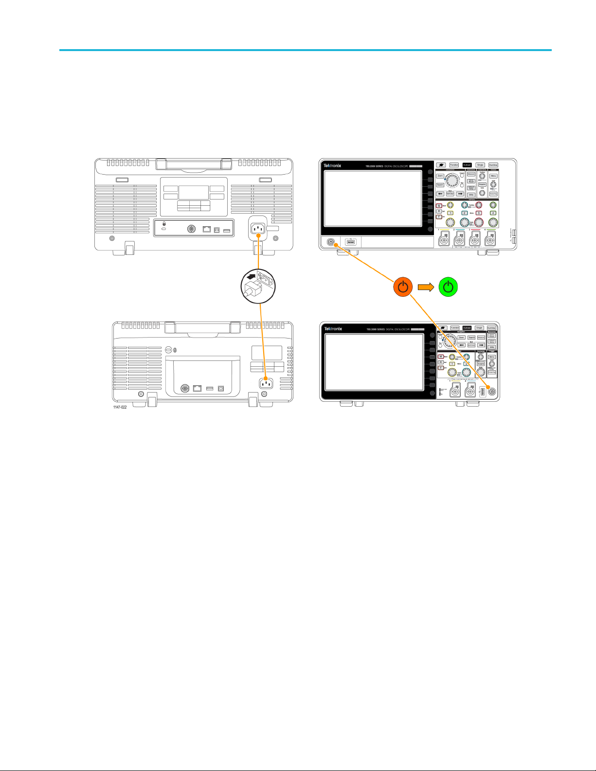
Powering on and off the oscilloscope
Grounding the oscilloscope is necessary for safety and to take accurate measurements. The oscilloscope must share the
same ground as any circuits that you are testing. You connect the oscilloscope to ground by plugging the three-pronged
power cord into an outlet grounded to earth ground.
To connect the power cord and power on the oscilloscope:
Getting acquain
ted with the oscilloscope
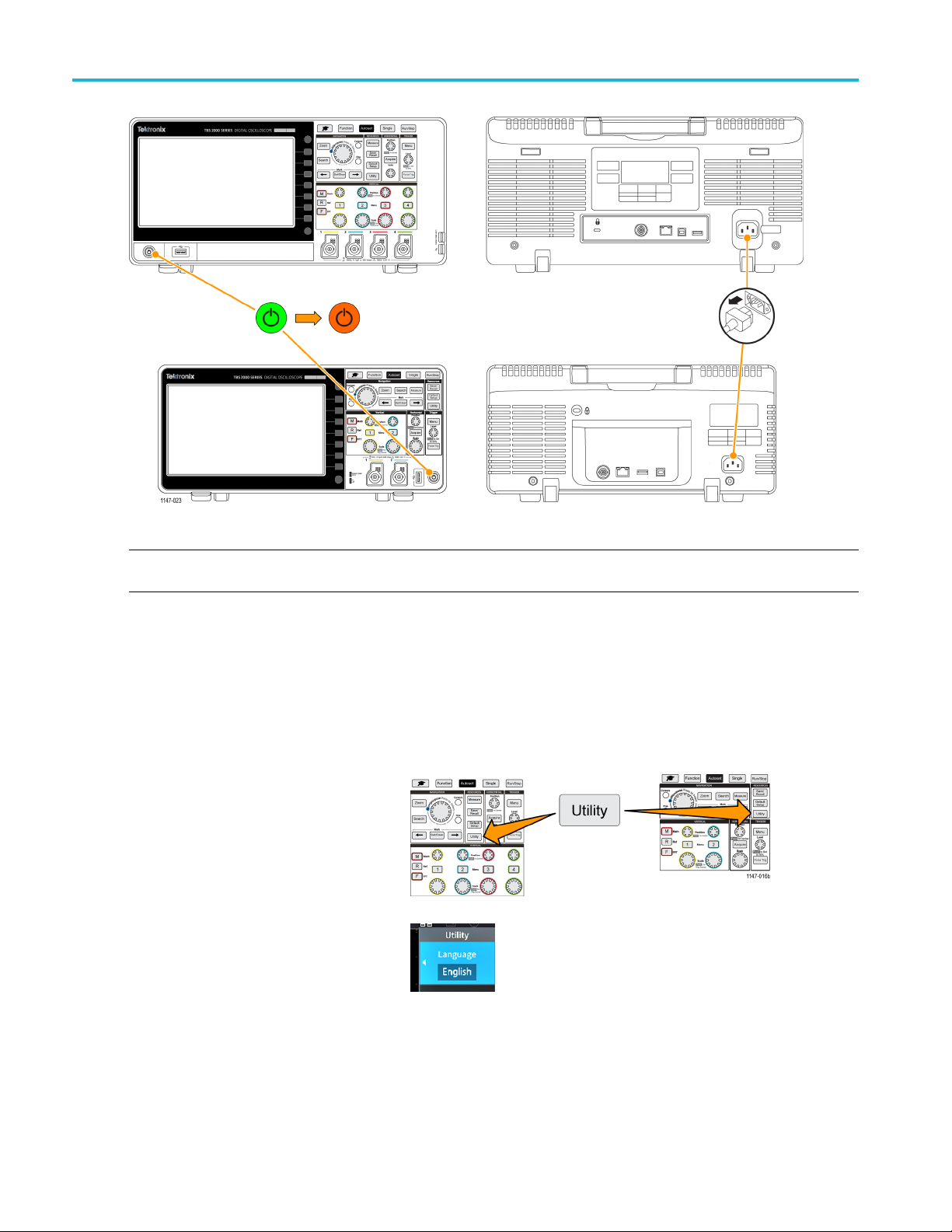
To power off the oscilloscope and remove the power cord:
TBS2000 Series User Manual 7
Getting acquain
ted with the oscilloscope
NOTE. The current instrument settings are stored in nonvolatile memory when you power off the oscilloscope. The
oscilloscope restores the settings when you power on.
Changing the user interface language
You can change the language used for the oscilloscope on-screen display, measurements, readouts, and menus to one of
11 languages.
The following steps show how to change the user interface language. These steps also introduce you to the oscilloscope
menu system.
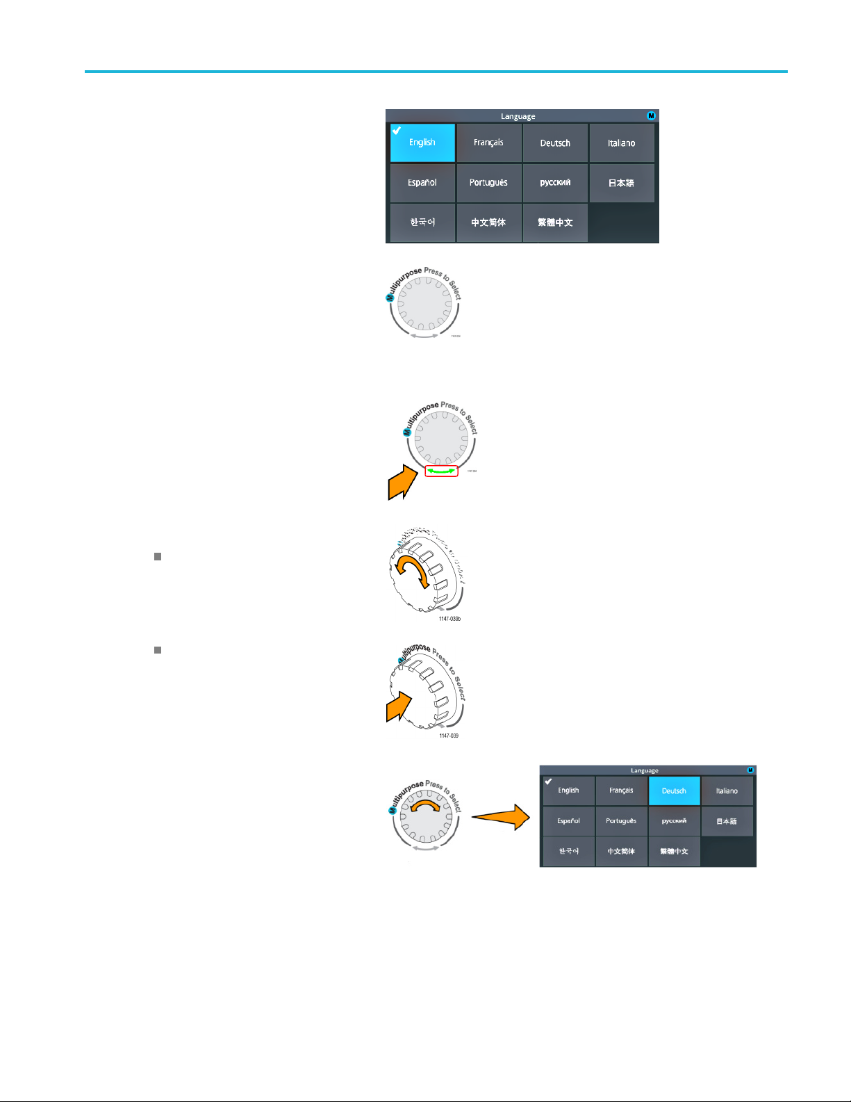
1. Push the Utility front-panel button. The
oscilloscope displays a side menu on the
right side of the screen.
htheLanguage side-menu button.
2. Pus
8 TBS2000 Series User Manual
Getting acquain
ted with the oscilloscope
The oscillosco
menu.
YouwillusetheMultipurpose knob
to select and c
following text describes how the
Multipurpose knob works.
The Multipurpose knob lets you interact with
on-screen m
boxes.
A blue-colored M icon on a menu, message,
or dialog bo
the Multipurpose knob to select and click
values in that item.
The turn arrow indicator, located below the
knob, turns green when you can use the
knob to ma
menu or dialog box.
pe opens the Language
lick menu items. The
enus, messages, and dialog
x label means that you can use
ke selections or enter values in a
The knob has two functions:
Select function, where you turn the
knob to select (highlight) a menu
item. Selecting a menu item does
not execute (run) that function.
Click function, where you push the
knob to either run the selected menu
item or enable a field in that menu
item to enter numbers or select
values.
3. Turn the Multipurpose knob to select a
uage.
lang
TBS2000 Series User Manual 9
Getting acquain
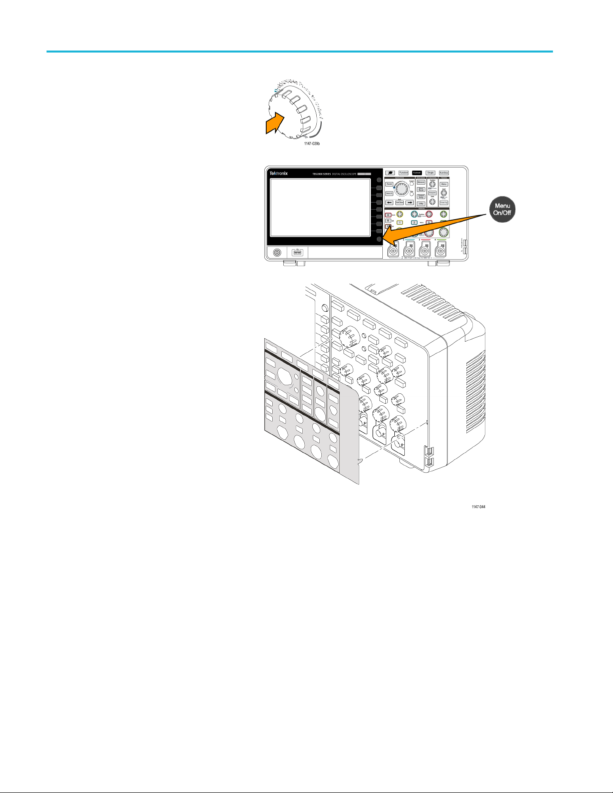
4. Click (push) the Multipurpo se knob
5. Push the Menu On /Off buttontoclose
ted with the oscilloscope
to enter the highlighted language.
The selected l
immediately.
the Utility
anguage takes effect
menu.
6. If you load
install the plastic overlay on the front
panel to provide labels in that language.
Fold the o
over the knobs until the knob hole tabs
click over the bottom edges of the knobs.
Insert t
slots.
If you are changing from a non English
languag
front-panel language overlay.
a language other than English,
verlay tabs. Push the overlay
he overlay tabs into the small
e to English, remove the
10 TBS2000 Series User Manual
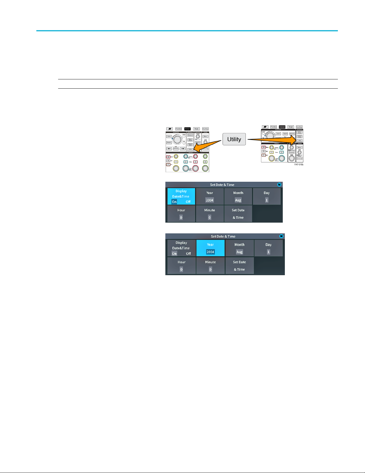
Changing the date and time
Set the current data and time so that files that you save are marked with the correct date and time. The date and time are
shown in the lower-right corner of the screen. Time is shown using a 24-hour clock.
NOTE. The clock does not automatically adjust for seasonal time changes. The calendar does adjust for leap years.
The following steps show how to set the oscilloscope clock with the current date and time. These steps also introduce
you to more functions of the menu system.
1. Push Utility front-panel button.
Getting acquain
ted with the oscilloscope
2. Push Set D
button. The oscilloscope shows the Set
Date & Time menu.
3. Turn the Multipurpose knob to select
the Yea
ate & Time side-menu
r field.
TBS2000 Series User Manual 11
Getting acquain
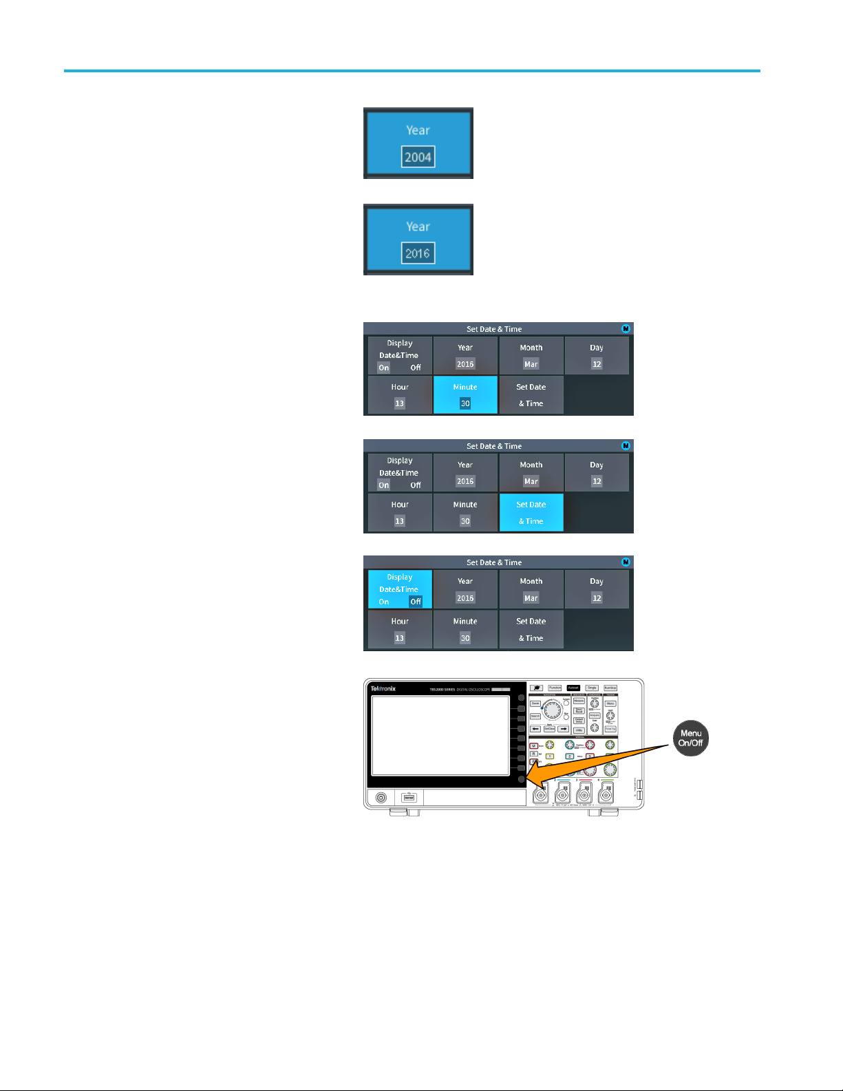
4. Click the Multipurpose knob to enable
5. Turn the Multipurpose knob to change
6. Repeat steps 3 – 5 to select and change
7. When you have finished making all date
ted with the oscilloscope
setting the year value. A white box is
drawn around t
that you can use the Multipurpose knob
to change that value.
the year value in the field.
When the val
Multipurpose knob. This enters the
number and returns the knob to menu
select mode
the remain
(Month, Day, Hour, Minute).
and time changes, turn the Multipurpose
knob to s
click the knob to enter the date/time
settings into the oscilloscope.
he number field, indicating
ue is correct, click the
.
ing date and time settings
elect Set Date & Time, then
8. To turn off displaying the date and time,
Display Date & Time and click the
select
Multipurpose knob to toggle On or Off.
9. Push the Menu On /Off buttontoclose
the Utility side menu.
The new date and time are shown in the
lower-right corner of the screen.
12 TBS2000 Series User Manual
 Loading...