

Page 1

tek.com/keithley
Model 2000-SCAN
Scanner Card for use with the DMM6500
User’s Manual
2000-SCAN-900-01 Rev. A / April 2018
*P2000-SCAN-900-01A*
2000-SCAN-900-01A
Page 2

Scanner Card
Model 2000-SCAN
User's Manual
© 2018, Keithley Instruments, LLC
Cleveland, Ohio, U.S.A.
All rights reserved.
Any unauthorized reproductio n, photocopy, or use of the information herein, in whole or in part,
without the prior written appro val of Keithley Instruments, LLC, is strictly prohibited.
These are the original instructions in English.
TSP®, TSP-Link®, and TSP-Net® are trademarks of Keithley Instruments, LLC. All Keithley
Instruments product names are t r ademarks or registered trademarks of Keithley Instruments, LLC.
Other brand names are trademarks or r egistered trademarks of their respec tive holders.
The Lua 5.0 software and associated documentation files are copyright © 1994 - 2015, Lua.org,
PUC-Rio. You can access terms of lic ens e for the Lua software and associated documentation at
the Lua licensing site (http://www.lua.org/license.html).
Microsoft, Visual C++, Excel, and W indows are either registered trademarks or trademarks of
Microsoft Corporation in the United States and/or other countries.
Document number: 2000-SCAN-900-01 Rev. A / April 2018
Page 3

Table of contents
General Information .................................................................................................... 1-1
Introduction .......................................................................................................................... 1-1
Features ............................................................................................................................... 1-1
Unpacking and inspection .................................................................................................... 1-1
Inspecting for damage ............................................................................................................... 1-1
Handling precautions ................................................................................................................ 1-2
Factory service ..................................................................................................................... 1-2
Card connections and installation ............................................................................ 2-1
Introduction .......................................................................................................................... 2-1
Installation handling precautions .......................................................................................... 2-1
Board cleaning ..................................................................................................................... 2-1
Connections ......................................................................................................................... 2-2
Connection precautions ............................................................................................................ 2-2
Card configurations ................................................................................................................... 2-2
Card connectors ........................................................................................................................ 2-4
Output connections ................................................................................................................... 2-5
Wiring procedures ..................................................................................................................... 2-5
Dressing leads .......................................................................................................................... 2-6
Typical connecting schemes ................................................................................................ 2-7
Voltage connections .................................................................................................................. 2-7
Resistance connections ............................................................................................................ 2-8
Card installation and removal ............................................................................................ 2-10
Scanner card installation ......................................................................................................... 2-11
Output connections to the multimeter ...................................................................................... 2-13
Scanner card removal ............................................................................................................. 2-14
Operation ..................................................................................................................... 3-1
Introduction .......................................................................................................................... 3-1
Signal limitation .................................................................................................................... 3-1
Relay input signal limitations ..................................................................................................... 3-1
Scanner card detection ........................................................................................................ 3-2
Power-up detection ................................................................................................................... 3-2
Scanner option remote command ............................................................................................. 3-2
Basic front-panel measurements ......................................................................................... 3-2
Opening and closing channels from the CHANNEL swipe screen ............................................ 3-2
Building a scan .......................................................................................................................... 3-4
RTD temperature measurements ........................................................................................ 3-6
Connecting RTD probes ............................................................................................................ 3-6
Setting up an RTD measurement on the front panel ................................................................. 3-7
Typical applications .............................................................................................................. 3-7
Resistor testing ......................................................................................................................... 3-7
Current measurements ........................................................................................................... 3-14
Measurement considerations ............................................................................................. 3-17
Page 4

Table of contents
User's Manual
Model 2000-SCAN Scanner Card
Path isolation ........................................................................................................................... 3-17
Magnetic fields ........................................................................................................................ 3-18
Electromagnetic interference (E M I) ......................................................................................... 3-18
Ground loops ........................................................................................................................... 3-19
Keeping connectors clean ....................................................................................................... 3-20
Page 5

Safety precautions
The following safety precautions should be observed before using this product and any associated instrumentation. Although
some instruments and accessories would normally be used with nonhaz ardous voltages, there are situations where hazardous
conditions may be present.
This product is intended for use by personnel who recognize shock hazards and are familiar with the safety precautions required
to avoid possible injury. Read and follow all installation, operation, and maintenance information carefully before using the
product. Refer to the user documentation for complete product specifications.
If the product is used in a manner not specified, the protection provided by the product warranty may be impaired.
The types of product users are:
Responsible body is the individual or group responsible for the use and maintenance of equipment, for ensuring that the
equipment is operated within its specifications and operating limits, and for ensuring that operator s are adequately trained.
Operators use the product for its i ntended function. They must be trained in electrical safety procedures and proper use of the
instrument. They must be protected from electric shock and contact wit h hazardous live circuits.
Maintenance personnel perform routine procedures on the product to keep it operating properly, for example, setting the line
voltage or replacing consumable materials. Maintenance procedures ar e described in the user documentation. The procedures
explicitly state if the operator may perform them. Otherwise, they should be performed only by service personnel.
Service personnel are trained to work on live circuits, perform safe installations, and repair products. Only properly trained
service personnel may perform ins tallation and service procedures.
Keithley products are designed f or use with electrical signals that are measurement, control, and data I/O connections, with low
transient overvoltages, and mus t not be directly connected to mains voltage or to voltage sources with high tr ans ient
overvoltages. Measurement Cat egory II (as referenced in IEC 60664) connections require protection for high transient
overvoltages often associated with local AC mains connections. Certai n K ei thley measuring instruments may be connected to
mains. These instruments will be mar k ed as category II or higher.
Unless explicitly allowed in the spec i fications, operating manual, and instrument labels, do not connect any instrument to mains.
Exercise extreme caution when a shock hazard is present. Lethal voltage may be present on cable connector jacks or test
fixtures. The American National S tandards Institute (ANSI) states that a shock hazard exists when voltage level s greater than
30 V RMS, 42.4 V peak, or 60 VDC are present. A good safety practice is to expect that hazardous voltage is present in any
unknown circuit before measuring.
Operators of this product must be protec ted from electric shock at all times. The responsible body must ensure that operators
are prevented access and/or insulated from every connection point. In some c ases, connections must be exposed to potential
human contact. Product operators i n these circumstances must be trained to pr otect themselves from the risk of electric shock. If
the circuit is capable of operating at or above 1000 V, no conductive part o f the circuit may be exposed.
Do not connect switching cards direc tly to unlimited power circuits. They are intended to be used with impedance-limited
sources. NEVER connect switching cards directly to AC mains. When connecting sources to switching ca rds, install protective
devices to limit fault current and v ol tage to the card.
Before operating an instrument, ensure that the line cord is connected to a properly-grounded power receptacle. Inspect the
connecting cables, test leads, and j umpers for possible wear, cracks, or breaks before each use.
When installing equipment where ac cess to the main power cord is restricted, such as rack mounting, a separate main input
power disconnect device must be prov i ded in close proximity to the equipment and within easy reach of the operator.
For maximum safety, do not touch the product, test cables, or any other instruments while power is applied to the circuit under
test. ALWAYS remove power from the entire test system and discharge any capacitors before: connecting or disconnecting
cables or jumpers, installing or rem oving switching cards, or making int ernal changes, such as installing or r emoving jumpers.
Do not touch any object that could pr ovide a current path to the common side of the circuit under test or power line (earth)
ground. Always make measurements with dry hands while standing on a dry, insulated surface capable of withstandin g the
voltage being measured.
Page 6

For safety, instruments and accessories must be used in accordance with the operating instructions. If the instruments or
accessories are used in a manner not s pecified in the operating instructions, the protection provided by the equipment may be
impaired.
Do not exceed the maximum signal levels of the instruments and accessori es. Maximum signal levels are defined in the
specifications and operating inf or mation and shown on the instrument panels, test fixture panels, and switching cards.
When fuses are used in a product, replac e with the same type and rating for continued protection against fire hazard.
Chassis connections must only be used as shield connections for measuring c i rcuits, NOT as protective earth (s afety ground)
connections.
If you are using a test fixture, keep the lid closed while power is applied to t he dev i ce under test. Safe operation requires the use
of a lid interlock.
screw is present, connect it to protective earth (safety ground) using the wire recommended in the user documentation.
If a
The
symbol on an instrument means caution, risk of hazard. The user must refer to the operating instructions located in the
user documentation in all cases where the symbol is marked on the instrument .
The
symbol on an instrument means warning, risk of electric shock. Use standard safety precautions to avoid pers onal
contact with these voltages.
The symbol on an instrument shows that the surface may be hot. Avoid personal contact to prevent burns.
The
If this
symbol indicates a connection terminal to the equipment frame.
symbol is on a product, it indicates that mercury is present in the display l amp. Please note that the lamp must be
properly disposed of according to federal, state, and local laws.
The WARNING heading in the user documentation explains hazards that might result in personal injury or death. Always read
the associated information very car efully before performing the indicated procedure.
The CAUTION heading in the user documentation explains hazards that could damage the inst rument. Such damage may
invalidate the warranty.
The CAUTION heading with the
symbol in the user documentation explains hazards that could result in moderate or minor
injury or damage the instrument. Always read the associated information very carefully before performing the indicated
procedure. Damage to the instrument may invalidate the warranty.
Instrumentation and accessories shall not be connected to humans.
Before performing any maintenance, disconnect the line cord and all test cables.
To maintain protection from electric shock and fire, replacement components in mains circuits — including the power
transformer, test leads, and input j ac ks — must be purchased from Keithley. S tandard fuses with applicable national safety
approvals may be used if the rating and type are the same. The detachable mains power cord provided with the instrum ent may
only be replaced with a similarly rated power cord. Other components that are not safety-related may be purchas ed from other
suppliers as long as they are equival ent to the original component (note that selected parts should be purchased on ly through
Keithley to maintain accuracy and f unctionality of the product). If you are unsure about the applicability of a replacement
component, call a Keithley office for information.
Unless otherwise noted in product-specific literature, Keithley instruments are designed to operate indoors only, in the following
environment: Altitude at or below 2,000 m (6,562 ft); temperature 0 °C to 50 °C (32 °F to 122 °F); and pollution degree 1 or 2.
To clean an instrument, use a cloth dampened with deionized water or mild, water-based cleaner. Clean the exterior of the
instrument only. Do not apply cleaner directly to the instrument or allow liquids to enter or spill on the instrument. Products that
consist of a circuit board with no case or chassis (e.g., a data acquisition board for installation into a computer ) should never
require cleaning if handled acc or ding to instructions. If the board becomes contaminated and operation is aff ec ted, the board
should be returned to the factory for proper cleaning/servicing.
Safety precaution revision as of J une 2017.
Page 7

Factory service ......................................................................... 1-2
In this section:
Introduction .............................................................................. 1-1
Features ................................................................................... 1-1
Unpacking and inspection ........................................................ 1-1
Introduction
This section contains general information about the 2000-SCAN Scanner Card. The 2000-SCAN is a
scanner card used in the DMM6500 6½ Digit Graphic al Sampling Multimeter. The 2000-SCAN
provides 10 channels of 2-pole relay switching. The channels can also be configured for 4-pole
operation.
Section 1
General Information
If you are using this scanner card with the 2700, 270 1, or 2750, please see the 2000-SCAN Scanner
Card Instruction Manual.
Features
Features of the scanner card include:
• Ten channels of 2-pole relay input.
• Configurable channels for 4-pole operation.
• Ability to multiplex one of ten 2-pole or one of five 4-pole channel s int o a DMM6500.
Unpacking and inspection
Inspecting for damage
The 2000-SCAN is packaged in a resealable, anti-st atic bag to protect from damage due to static
discharge and contamination that could degrade it s performance. Before removing the card from the
bag, observe the following handling precautions.
Page 8

Section
User's Manual
1: General Information Model 2000-SCAN Scanner Card
Handling precautions
• Always grasp the card by the side edges and cover s. Do not touch the board surfaces or
components.
• When the card is not installed in a multimeter, keep the card in the anti-static bag and store it in
the original packing carton.
• After removing the card from its anti-static bag, inspect it for any obvious signs of physical
damage. Report any such damage to the shipping agent immediately.
Factory service
To return the scanner card to Keithley Instruments for repair:
• Call the Repair Department at 1-800-833-9200 or send an email to
RMAREQUEST@tektronix.com for a Return Material Authorization (RMA) n um ber.
• Carefully pack the instrument in the original packi ng carton.
• Write ATTENTION REPAIR DEPARTMENT and the RMA number on the shipping label.
1-2 2000-SCAN-900-01 Rev. A / April 2018
Page 9

Card installation and removal ................................................. 2-10
In this section:
Introduction .............................................................................. 2-1
Installation handling precautions .............................................. 2-1
Board cleaning ......................................................................... 2-1
Connections ............................................................................. 2-2
Typical connecting schemes .................................................... 2-6
Introduction
This section includes information on making conne ct i ons t o the 2000-SCAN Scanner Card and
installing the scanner card in a DMM6500.
Section 2
Card connections and installation
The information in this topic is intended only for qualified service personnel. Some of the
procedures may expose you to hazardous voltages that could result in personal injury or
death. Do not attempt to perform these procedures unless you are qualified to do so.
Installation handling precautions
To maintain high-impedance isolation between cha nnels, avoid contamination from foreign materials
as body oils when handling the scanner card. Contamination can substantially lower leakage
resistances, degrading card performance. To avoid possible contamination, always hold the scanner
card by the side edges or covers. Do not touch board surfaces, components, or areas adjacent to
electrical contacts.
Dirt build-up over a period of time is another possible source of contamination. To avoid this problem,
operate the multimeter and scanner card in a clean env i ronment.
Board cleaning
The circuit board should be thoroughly cleaned with pure water after soldering to remove all
contaminants. After cleaning with water, swab t he area with pure methanol and allow the board to dry
for several hours in a 50 °C environment before use.
Page 10

Section
User's Manual
2: Card connections and installation Model 2000-SCAN Scanner Card
Connections
This section provides information on connecti ng your external test circuitry to the scanner card.
Failure to observe the following precautions may result in degraded card performance.
Connection precautions
Connection and wiring procedures in this document are intended for use by qualified
personnel only. Do not perform these procedures unless qualified to do so. Failure to
recognize and observe normal safety precautions could result in personal injury or death.
Do not attempt to perform this procedure unless qualified to do so. Failure to recognize and
observe normal safety precautions could result in personal injury or death.
Do not exceed the maximum specifications for the 2000-SCAN Scanner Card. Refer to the
specifications provided in the data sheet. Failure to recognize and observe normal safety
precautions could result in personal injury or death.
As described in the International Electrotechnical Commission (IEC) Standard IEC 664 ,
scanner cards are Installation Category I and must not be connected to mains.
To prevent electric shock that could result in serious injury or death, make sure the DMM
power is turned off and power is removed from all external circuitry before making or
breaking connections to the scanner card.
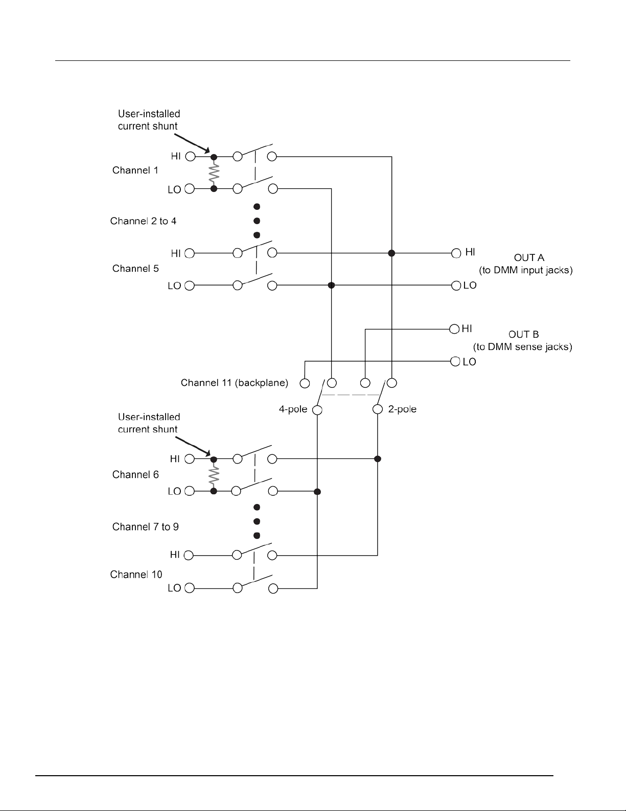
Card configurations
The following figure shows a simplified diagram of t he 2000-SCAN. The scanner card has 10 input
channels and two outputs. Channels 1 to 10 are all switched by the relays.
4-pole paired channels are as follows:
• Channels 1 and 6
• Channels 2 and 7
• Channels 3 and 8
• Channels 4 and 9
2-2 2000-SCAN-900-01 Rev. A / April 2018
• Channels 5 and 10
Page 11
Model 2000
Card connections and installation
-SCAN Scanner Card User's Manual Section 2:
Figure 1: Simplified schematic
2000-SCAN-900-01 Rev. A / April 2018 2-3
Page 12

Section
User's Manual
2: Card connections and installation Model 2000-SCAN Scanner Card
Card connectors
The following figure shows the input and output connectors for the card. Card connectors include:
• CH 1 to 10 (channels 1 to 10): HI and LO input terminals prov ided for each of the 10 channels on
the card.
• OUT A: HI and LO output connections for all 10 channels in 2-pole mode or channels 1 to 5 in
4-pole mode.
• OUT B: HI and LO output connections for channels 6 t o 10 i n 4-pole mode.
To access the connectors, open the plastic shield by pressing in the locking tab, and swing the shield
away from the circuit board.
Figure 2: Card connectors
2-4 2000-SCAN-900-01 Rev. A / April 2018
Page 13

Model 2000
Card connections and installation
-SCAN Scanner Card User's Manual Section 2:
Output connections
When making output connections from your 2000 -SCAN to a DMM6500, use the supplied test leads
for scanner output connections.
To make output connections to your DMM6500:
1. Connect the red leads to the output (OUT A and OUT B) HI terminals.
2. Connect the black leads to the output LO terminals. See the following figure for details.
3. Dress the output test leads through the cable clam p.
4. After all wires are connected and secure, close t he pl astic shield, and secure it with the locking
tab.
Figure 3: Output connections
2000-SCAN-900-01 Rev. A / April 2018 2-5
Wiring procedures
Before connecting or disconnecting wires, all power must be off and stored energy in
external circuitry discharged.
Page 14

Section
User's Manual
2: Card connections and installation Model 2000-SCAN Scanner Card
Mechanical shock may open or close latching relays on the scanner card. Before enabling
any external sources, open all relay s by inser ti ng the 2000-SCAN into the multimeter and
turning on the power.
To wire the circuitry to the screw terminals on the scanner card:
1. To access the connectors, open the plastic shield.
2. Strip approximately 7.93 mm (5/16 in.) of insulation from the end of each wire.
3. Twist the strands of the wire together.
#22 AWG stranded wire is recommended for scanner card connections.
4. Loosen the screw terminal.
5. Insert the wire into the access hole.
6. While holding the wire in place, tighten the connector screw securely.
7. Repeat the above steps until all wires are connect ed.
8. Dress input wires through the cable clamp.
Dressing leads
After the wires are connected to the terminal blocks, they should be dressed through the cable clamp
as shown in the figure below. Unlatch the clip that holds the cable clamp together, then route all wires
flat against the lower half of the clamp. Clamp the wires down, then secure the clamp with the
unlatched metal clip.
Figure 4: Routing wires through the cable clamp
2-6 2000-SCAN-900-01 Rev. A / April 2018
Page 15

Model 2000
Card connections and installation
-SCAN Scanner Card User's Manual Section 2:
Typical connecting schemes
This section discusses typical connections for the scanner card.
Voltage connections
The figure below shows typical connections for v ol tage measurements. Note that all channels are
used in the 2-pole mode and that up to 10 voltage source s can be switched with this configuration.
This basic configuration can be used for the following t ypes of measurements:
• DCV
• ACV
• Frequency (voltage only)
• Digitize voltage
Figure 5: Connections for voltage scanning
2000-SCAN-900-01 Rev. A / April 2018 2-7
Page 16

Section
User's Manual
2: Card connections and installation Model 2000-SCAN Scanner Card
Resistance connections
Making 2-pole connections
The following figure shows typical 2-pole resistor connections. The 2-pole resistance configuration
can be used to test up to ten devices under test (DUTs).
Figure 6: Typical connections for 2-wire resistance scanning
2-8 2000-SCAN-900-01 Rev. A / April 2018
Page 17

Model 2000
Card connections and installation
-SCAN Scanner Card User's Manual Section 2:
Making 4-pole connections
Typical 4-pole resistance connections are shown in the following figure. This general configuration
can be used with all channels to scan:
• 4-wire resistance measurements
• 4-wire RTD temperature measurements
Figure 7: Typical connections for 4-wire resistance scanning
2000-SCAN-900-01 Rev. A / April 2018 2-9
Page 18
Section
User's Manual
2: Card connections and installation Model 2000-SCAN Scanner Card
Card installation and removal
This section explains how to install and remove the 2000-SCAN scanner card from the DMM6500. All
wiring connections must be complete before install i ng the 2000-SCAN.
The information in this topic is intended only for qualified service personnel. Some of the
procedures may expose you to hazardous voltages that could result in personal injury or
death. Do not attempt to perform these procedures unless you are qualified to do so.
To prevent electric shock that could result in injury or death, never handle a scanner card
that has power applied to it. Before installing or removing a scanner card, make sure the
2000-SCAN is turned off and disconnected from line power. If the scanner card is connected
to a DUT, make sure power is removed from all external circuitry.
If a card slot is unused, you must install slot covers to prevent personal contact with high
voltage circuits. Failure to install slot covers could result in personal exposure to hazardous
voltages, which could cause personal injury or death if contacted.
If you have a 2000-SCAN or 2001-TCSCAN that was used in another Keithley Instruments product,
such as the Model 2000, you can use your existing scan cards in the DMM6500. Follow the
instructions in your original equipment docume ntation to remove the card from the instrument, then
use the following instructions to install it in the DMM6 500. You do not need to remove the wiring to
the card.
For inexperienced users, it is recommended that you do not connect a device under test (DUT) and
external circuitry to the scanner card. This allows you to exercise close and open operations without
the dangers associated with live test circuit s. You can also set up pseudocards to experiment with
switching.
Select the rear inputs with the multimeter front-panel TERMINALS switch when using the scanner
card.
2-10 2000-SCAN-900-01 Rev. A / April 2018
Page 19

Model 2000
Card connections and installation
-SCAN Scanner Card User's Manual Section 2:
Scanner card installation
Turn off power to all instruments (including the multimeter), and disconnect all power cords.
Make sure all power is removed and any stored energy in external circuitry is discharged.
To prevent contamination of the 2000-SCAN that c ould degrade performance, handle the scanner
card by the edges and covers only.
The figure below demonstrates the 2000-SCAN installation.
Figure 8: Unlock card
2000-SCAN-900-01 Rev. A / April 2018 2-11
Page 20

Section
User's Manual
2: Card connections and installation Model 2000-SCAN Scanner Card
Figure 9: Lock card
To install your 2000-SCAN:
1. Remove power from the DMM6500.
2. Disconnect the power cord and any other cables that are connected to the rear panel.
3. Remove the cover plate from the Accessory Card Sl ot on the rear panel of the multimeter. To do
so, move the tab on the cover plate up and out.
4. Slide the card edges into the guide rails inside the multimeter.
5. With the ejector arms in the unlocked position, carefully push the card all the way forward until the
arms engage the ejector clips. Push both arms inward to lock the scanner card into the
multimeter.
6. After installing your scanner card, make your output connections.
2-12 2000-SCAN-900-01 Rev. A / April 2018
Page 21
Model 2000
Card connections and installation
-SCAN Scanner Card User's Manual Section 2:
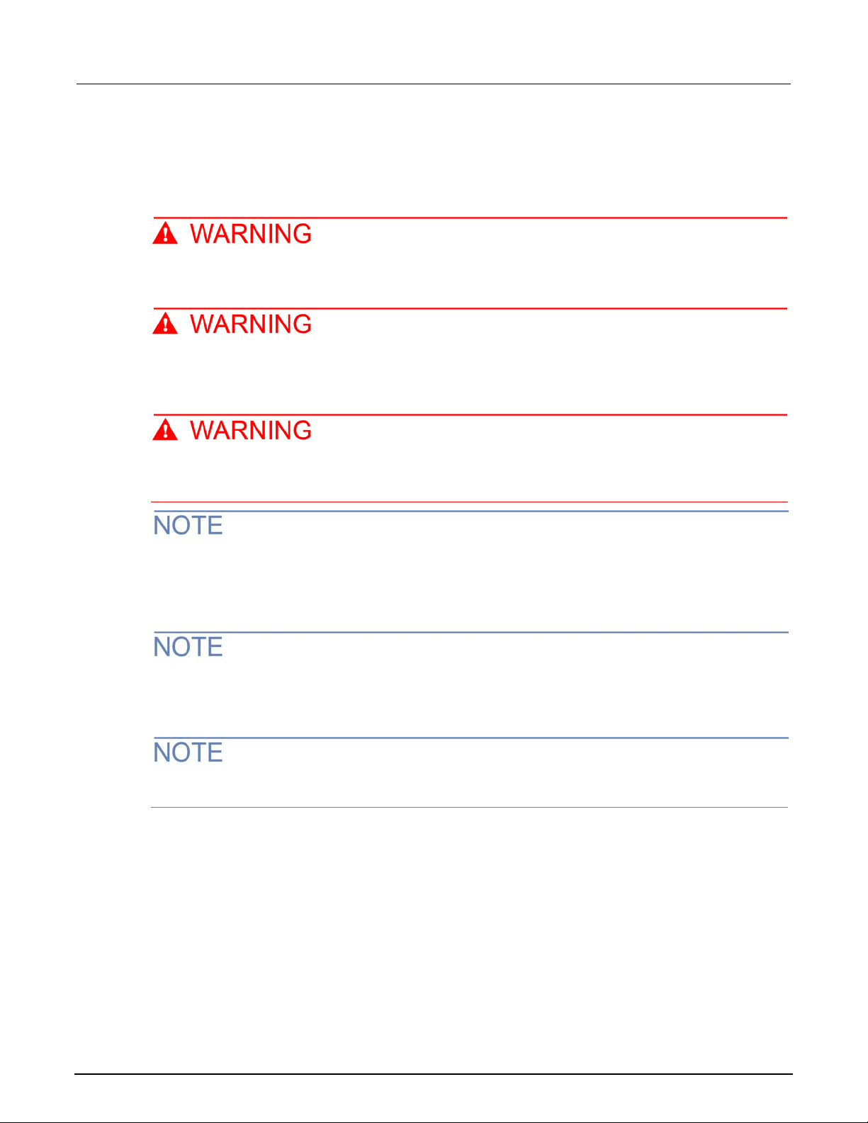
Output connections to the multimeter
After installing the 2000-SCAN, connect t he scan ner card output leads to the multimeter rear panel
jacks.
To connect the output leads for 2-pole connection:
1. Connect OUT A HI (red) to INPUT HI.
2. Connect OUT A LO (black) to INPUT LO.
See the following figure.
Figure 10: 2-pole output connections
2000-SCAN-900-01 Rev. A / April 2018 2-13
Page 22
Section
User's Manual
2: Card connections and installation Model 2000-SCAN Scanner Card
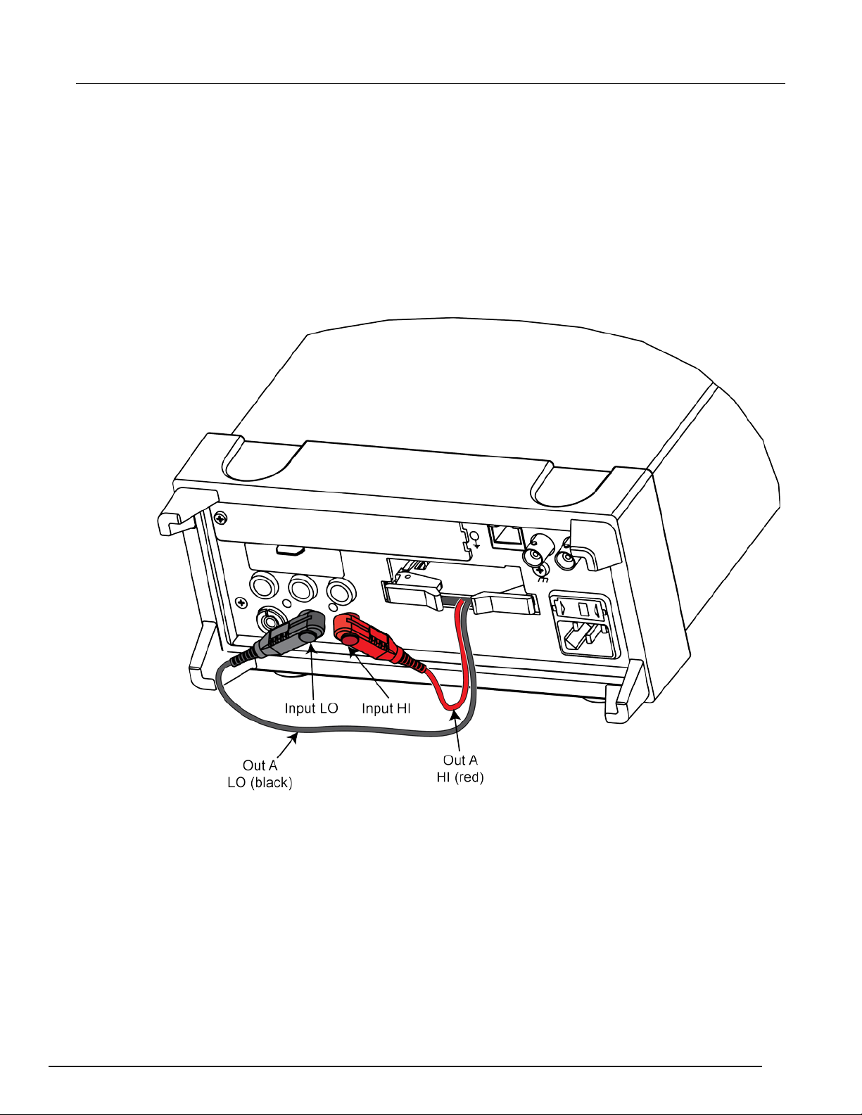
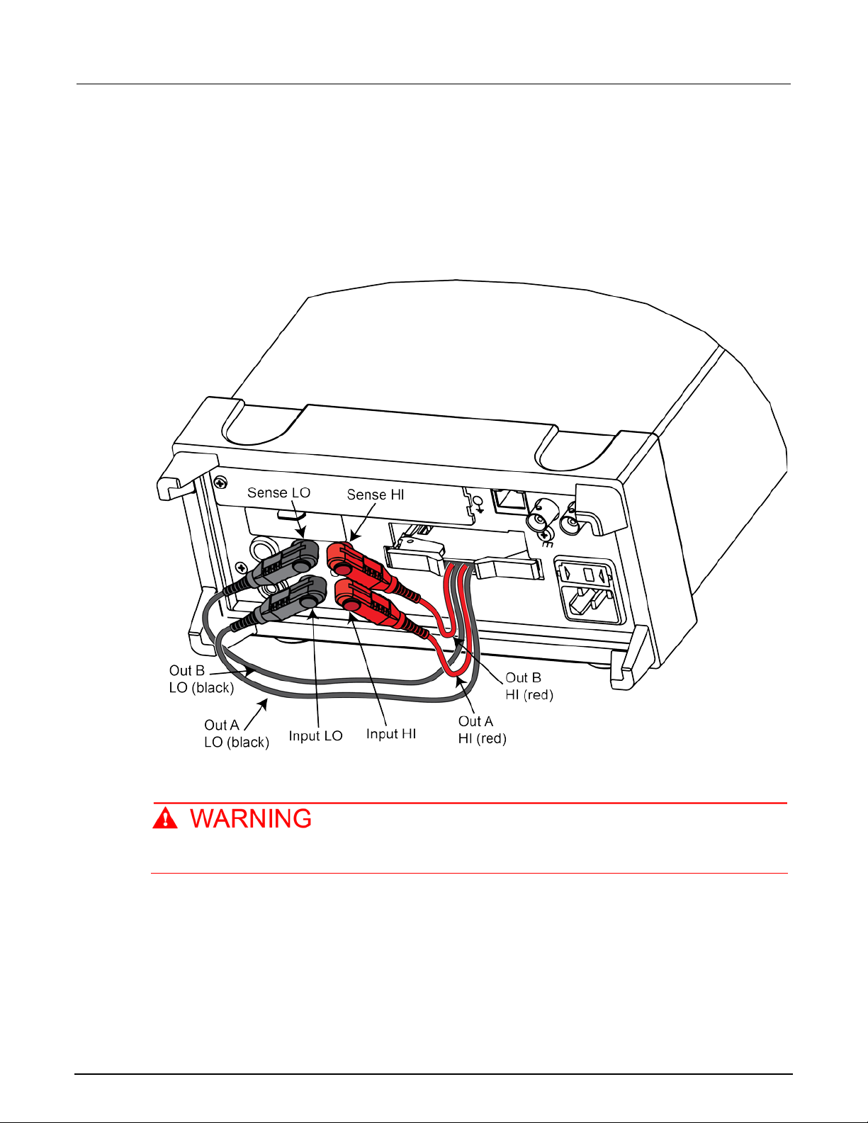
To connect the output leads for 4-pole connection:
1. Connect OUT A HI (red) to INPUT HI.
2. Connect OUT A LO (black) to INPUT LO.
3. Connect OUT B HI (red) to SENSE HI.
4. Connect OUT B LO (black) to SENSE LO.
See the following figure.
Figure 11: 4-pole output connections
Scanner card removal
Turn off power to all instrumentation, including the multimeter, and disconnect all line cords.
Make sure all power is removed and any stored energy in external circuitry is discharged.
To remove the scanner card from th e m ultimeter:
1. Unlock the scanner card by pulling the ejector arms outward.
2. Carefully slide the scanner card out of the multimet er.
3. If you will operate the DMM6500 without the scanner card installed, install the cover plate over
the Accessory Card Slot.
2-14 2000-SCAN-900-01 Rev. A / April 2018
Page 23

Measurement considerations ................................................. 3-17
In this section:
Introduction .............................................................................. 3-1
Signal limitation ........................................................................ 3-1
Scanner card detection ............................................................ 3-2
Basic front-panel measurements .............................................. 3-2
RTD temperature measurements ............................................. 3-6
Typical applications .................................................................. 3-7
Introduction
This section contains detailed information on front panel and remote interface operation of the
2000-SCAN.
Section 3
Operation
Before using the 2000-SCAN, you should be thoroughly familiar with the operation of the
DMM6500 multimeter. See the DMM6500 User's and Reference Manuals for the necessary
information.
Signal limitation
To prevent damage to the 2000-SCAN, do not ex ceed the maximum level specifications of the
scanner card.
Relay input signal limitations
Channels 1 to 10 are all relay inputs. To prevent overheating or damaging the relays, never exceed
the following maximum signal levels for these channe l s:
• DC signals: 110 VDC, 1 A switched, 30 VA (resistive load)
• AC signals: 125 V
or 175 VAC
RMS
, 1 A switched, 62.5 VA (resistive load)
PEAK
Page 24

Section
User's Manual
3: Operation Model 2000-SCAN Scanner Card
Scanner card detection
Power-up detection
The scanner card is detected when the power is turned on. If the scanner card is plugged in after the
power is turned on, the scanner card will not be rec ognized.
Installing the scanner card with the multimeter powered on may result in damage to both the
2000-SCAN and the multimeter.
Scanner option remote command
If the card is not present when powering on the instrument , scanner remote commands will generate
an error, and front panel operations related to the sc anner will inform you that no scanner card is
present.
:SYSTem:CARD<n>:IDN? is a SCPI command that will determine whethe r s canner card is installed.
The TSP command equivalent is print(slot[n].idn). The response to this query indicates
whether a scanner card is present as follows:
• 0 : Scanner not installed.
• 2000,10-Chan\Mux,0.0.0a,00000000 : Scanner installed
Basic front-panel measurements
The following procedures show you how to make a measurement, access settings for the
measurement, and view measurement data in a reading buffer. To build scans using the 2000-SCAN,
you must make sure your DMM6500 is set to use the rear terminals.
Opening and closing channels from the CHANNEL swipe screen
You can open and close channels on the DMM6500 from the CHANNEL and the SCAN swipe
screens.
To open and close channels from th e CH AN NE L swipe screen:
1. From the Channel tab on the swipe screen, select the SELECT icon to access the 2000-SCAN
channel list.
3-2 2000-SCAN-900-01 Rev. A / April 2018
Page 25

Model 2000
Operation
-SCAN Scanner Card User's Manual Section 3:
2. From the 2000-SCAN channel list, select the box next to the channel number to open or close it.
Selecting the channel box again will open the channel, and the connection icon will move to the
open state.
Figure 12: DMM6500 channel list
3. When closing a channel, select the measurement function for that channel from Measure
Functions screen. Note that you will select a measurement function for each channel you close.
Figure 13: Measurement function screen
4. Select OK.
2000-SCAN-900-01 Rev. A / April 2018 3-3
Page 26

Section
Manual
3: Operation Model 2000-SCAN Scanner Card User's
Controlling channels using the remote interface
Use the SCPI command :SENSE:FUNC to program functions for the selected channels. For TSP, use
the command channel.setdmm(). For example, to measure DC volts on channel 1, AC volts on
channel 2, and 2-wire resistance on channel 3, you w oul d use the following SCPI commands:
:SENS:FUNC "VOLT:DC", (@1)
:SENS:FUNC "VOLT:AC", (@2)
:SENS:FUNC "RES", (@3)
The TSP equivalent for the above commands are:
channel.setdmm("1", dmm.ATTR_MEAS_FUNCTION, dmm.FUNC_DC_VOLTAGE)
channel.setdmm("2", dmm.ATTR_MEAS_FUNCTION, dmm.FUNC_AC_VOLTAGE)
channel.setdmm("3", dmm.ATTR_MEAS_FUNCTION, dmm.FUNC_RESISTANCE)
To use the same function (DCV in this example) on al l three channels, use a single SCPI command
like the following example:
:SENS:FUNC "VOLT:DC", (@1:3)
The TSP equivalent for the above command is:
channel.setdmm("1:3", dmm.ATTR_MEAS_FUNCTION, dmm.FUNC_DC_VOLTAGE)
Building a scan
Front panel scan controls are located on the SCAN swipe screen. Select BUILD SCAN to build a
scan. If a scan is already configured, select the icon on the top right of the SCAN swipe screen to
access the Scan menu.
Figure 14: DMM6500 SCAN swipe screen
3-4 2000-SCAN-900-01 Rev. A / April 2018
Page 27

Model 2000
Operation
-SCAN Scanner Card User's Manual Section 3:
Selecting channels for a scan
To select channels from the front panel:
1. From the Build Scan screen, select Add Group of Channels t o access the 2000-SCAN channel
list. If you selected the channels for your scan from the Channels tab on the swipe screen, you
can skip this step.
Figure 15: Add group of channels
2. From the 2000-SCAN channel list, select the box next to the channel number to select your
channels.
3. Select OK to proceed to the Measurement Functions/Digitize Fun cti ons screen.
Selecting a measurement function
After choosing the channels for your scan, the Measu rement Functions screen opens. On this screen,
you can select the required function for your scan.
The available measurement functions are shown below.
Figure 16: Measurement functions
2000-SCAN-900-01 Rev. A / April 2018 3-5
Page 28

Section
User's Manual
3: Operation Model 2000-SCAN Scanner Card
Selecting a measurement function assigns it to the channel you selected. To assign the same
measurement function to all selected channel s, select the same measurement function for each
channel.
Run a scan
Once the scan is set up, you can run it.
To start the scan from the front panel, use one of the following:
• Press the TRIGGER key.
• On the Scan menu, select Start.
• On the Scan swipe screen, select Start Scan.
• From the trigger mode indicator on the home screen, select Initiate Scan.
You can pause the scan from scan swipe screen on the front panel . Select Pause Scan. To continue
the scan, select Resume Scan.
Stop a scan
You can stop a running scan.
When you stop a scan, the channels remain in the state they were in (opened or closed) when the
scan was stopped.
To stop a scan from the front panel:
Select Abort Scan from the Scan menu, the Scan swipe screen, or the trigger mode indicator on the
home screen.
• On the Scan menu, select Abort Scan.
• On the Scan swipe screen, select Abort Scan.
• From the trigger mode indicator on the home screen, select Abort Scan.
RTD temperature measurements
You can make resistance temperature detector (RTD) measurements when the 2000-SCAN is
installed. The following section provides procedures for making temperature measurements from the
front panel using the scanner card. For more detailed information on temperature measurements in
general, refer to the Model DMM6500 Reference Manual.
Connecting RTD probes
Connect RTD probes to the scanner using the basic re sist ance connections outlined in the DMM6500
reference manual. For 4-wire probes, pair the connection as follows:
• Channels 1 and 6: probe #1
• Channels 2 and 7: probe #2
• Channels 3 and 8: probe #3
• Channels 4 and 9: probe #4
• Channels 5 and 10: probe #5
3-6 2000-SCAN-900-01 Rev. A / April 2018
Page 29

Model 2000
Operation
-SCAN Scanner Card User's Manual Section 3:
Setting up an RTD measurement on the front panel
To set up an RTD measurement on the front panel:
1. After selecting the channels for your scan, select Temperature.
2. From the SETTINGS tab, select the Transducer options.
3. Select 2-Wire RTD, 3-Wire RTD, or 4-Wire RTD.
4. Below the Transducer options, the selected transducer type will have RTD options. Select the
appropriate RTD type.
5. Next to Unit, use the selection button to choose between Celsius, Fahrenheit, or Kelvin.
6. Set the NPLC to 1.
7. Select the SCAN tab.
8. Set the scan count.
9. Set the scan interval.
10. You can now start your scan in one of two ways:
Select Start on the SCAN screen.
Press the TRIGGER key, and select a measurement state. Select I nitiate Scan to start the
scan.
Typical applications
Resistor testing
The 2000-SCAN can be used to test up to 10 resistors using 2-wire measurements or up to f i ve
resistors using 4-wire measurements. These tests use the DMM6500 2-wire and 4-wire resistance
functions.
2000-SCAN-900-01 Rev. A / April 2018 3-7
Page 30

Section
User's Manual
3: Operation Model 2000-SCAN Scanner Card
Two-wire resistance tests
The figure below shows a typical setup for making 2 -wire resistance measurements. The following
figure shows an equivalent circuit. The 2000-SCAN provides the switching function, while the
resistance measurements are made by the DMM650 0. Since only 2-pole switching is required for this
application, one 2000-SCAN can be used to switch up to 10 resistors.
Figure 17: Two-wire resistance test configuration
Figure 18: Two-wire resistance test equivalent circu it
3-8 2000-SCAN-900-01 Rev. A / April 2018
Page 31

Model 2000
Operation
*RST
Puts the DMM in a known state
FUNC 'RES', (@1:10)
Sets the channels for 2-wire measurements
RES:RANG 100e3, (@1:10)
Sets the range to 100 kΩ
ROUT:SCAN:CRE (@1:10)
Creates the scan
ROUT:SCAN:COUN:SCAN 1
Sets the scan count
TRAC:CLE
Clears the buffer
INIT
Initiates the scan
reset()
Puts the DMM in a known state
channel.setdmm("1",
dmm.ATTR_MEAS_FUNCTION,dmm.FUNC_RESISTANCE)
Sets the channels for 2-wire
measurements
channel.setdmm("1:10", dmm.ATTR_MEAS_RANGE, 100e3)
Sets the range to 100 kΩ
scan.create("1:10")
Creates the scan
scan.scancount = 1
Sets the scan count
defbuffer1.clear()
Clears the buffer
trigger.model.initiate()
Initiates the scan
-SCAN Scanner Card User's Manual Section 3:
Use the SCPI commands below to set up a 2-wire resistance test using the DMM6500 and your
2000-SCAN.
Below is the TSP equivalent to set up a 2-wire resistance test using the DMM6500 and your
2000-SCAN.
Measurement accuracy can be optimized with minimal residual resistance. Make connecting wires as
short as practical and limit the number of connectors to minimize path resistance. You can also short
one of the scanner channel inputs, close the short ed channel, and enable the DMM REL feature to
null the path resistance. REL must be enabled for the entire test.
2000-SCAN-900-01 Rev. A / April 2018 3-9
Page 32

Section
User's Manual
3: Operation Model 2000-SCAN Scanner Card
Four-wire resistance tests
Precise measurements over a range of system and DUT c onditions can be obtained by using the
4-wire measurement scheme shown below. Separate sense leads from the DMM6500 are routed
through the scanner card to the DUT. The extra set of sens e l eads minimizes the effects of voltage
drops across the test leads, reducing measurement errors with lower DUT resistances. Note that an
extra two poles of switching are required for each re sistor tested. Only five resistors can be tested
using this configuration. The second figure show s an equivalent circuit for the 4-wire resistance test.
3-10 2000-SCAN-900-01 Rev. A / April 2018
Page 33

Model 2000
Operation
*RST
Puts the DMM in a known state
FUNC 'FRES', (@1:5)
FRES:OCOM ON, (@1:5)
Turns on offset compensation
FRES:RANG 100, (@1)
Sets the range to 100 Ω
FRES:RANG 10, (@2:3)
Sets the range to 10 Ω
FRES:RANG 1, (@4:5)
Sets the range to 1 Ω
ROUT:SCAN:CRE (@1:5)
Creates the scan
ROUT:SCAN:COUN:SCAN 1
Sets the scan count
TRAC:CLE
INIT
Initiates the scan
reset()
Puts the DMM in a known state
channel.setdmm("1:5", dmm.ATTR_MEAS_FUNCTION,
dmm.FUNC_4W_RESISTANCE)
Sets up the channels for 4-wire
measurements
channel.setdmm("1:5", dmm.ATTR_MEAS_OFFCOMP_ENABLE,
dmm.OCOMP_ON)
Turns on offset compensation
channel.setdmm(1, dmm.ATTR_MEAS_RANGE, 100)
Sets the range to 100 Ω
channel.setdmm("2:3", dmm.ATTR_MEAS_RANGE, 10)
Sets the range to 10 Ω
channel.setdmm("4:5", dmm.ATTR_MEAS_RANGE, 1)
Sets the range to 1 Ω
scan.create("1:5")
scan.scancount = 1
Sets the scan count
defbuffer1.clear()
Clears the buffer
trigger.model.initiate()
Initiates the scan
-SCAN Scanner Card User's Manual Section 3:
Figure 19: Four-wire resistance test equivalent circu it
Use the SCPI commands below to set up a 4-wire resistance test using the DMM6500 and your
2000-SCAN.
Sets up the channels for 4-wire measurements
Clears the buffer
Below is the TSP equivalent to set up a 4-wire resistance te st using the DMM6500 and your
2000-SCAN.
Creates the scan
2000-SCAN-900-01 Rev. A / April 2018 3-11
Page 34

Section
User's Manual
3: Operation Model 2000-SCAN Scanner Card
Combining 2-pole and 4-pole switching
The 2000-SCAN can combine 2- and 4-pole switchi ng in various combinations. This is useful if you
require 4-pole switching for only two resistors. The remaining resistors can be tested using
conventional 2-pole switching.
The figure below shows a test configuration using mixed 2- and 4-pole switching. Four-pole switching
is only used for device 1 (connected to channels 1 an d 6) and device 2 (connected to channels 2 and
7). Six more resistors are tested using 2-pole switchin g.
Figure 20: Combining 2-pole and 4-pole switching
3-12 2000-SCAN-900-01 Rev. A / April 2018
Page 35

Model 2000
Operation
*RST
Puts the DMM in a known state
FUNC 'FRES', (@1:2)
Sets the channels for 4-wire measurements
FRES:OCOM ON, (@1:2)
Turns on offset compensation
FRES:RANG 100, (@1:2)
Sets the 4-wire range to 100 Ω
FUNC 'RES', (@3:5, 8:10)
Sets the channels to 2-wire measurement
RES:RANG 100e3, (@3:5, 8:10)
Sets the 2-wire range to 100 kΩ
ROUT:SCAN:CRE (@1:5, 8:10)
Creates the scan
ROUT:SCAN:COUN:SCAN 1
Sets the scan count
TRAC:CLE
Clears the buffer
INIT
Initiates the scan
reset()
Puts the DMM in a known state
channel.setdmm("1:2, dmm.ATTR_MEAS_FUNCTION,
dmm.FUNC_4W_RESISTANCE)
Sets channels for 4-wire
measurements
channel.setdmm("1:2", dmm.ATTR_MEAS_OFFCOMP_ENABLE,
dmm.OCOMP_ON)
Turns on offset compensation
channel.setdmm("1:2", dmm.ATTR_MEAS_RANGE, 100)
channel.setdmm("3:5, 8:10", dmm.ATTR_MEAS_FUNCTION,
dmm.FUNC_RESISTANCE)
Sets channels to 2-wire
measurement
channel.setdmm("3:5, 8:10", dmm.ATTR_MEAS_RANGE, 100e3)
Sets 2-wire range to 100 kΩ
scan.create("1:5, 8:10")
Creates scan
scan.scancount = 1
Sets the scan count
defbuffer1.clear()
Clears buffer
trigger.model.initiate()
Initiates trigger model
-SCAN Scanner Card User's Manual Section 3:
Measurement functions for each scanner channel are defined using the FUNCTION menu when
building a scan. Measurement functions for this test would be set up as follows:
• Channels 1 and 2: 4W Ω
• Channels 3, 4, 5, and 8, 9, 10: 2 WΩ
Functions cannot be defined for channels 6 and 7 with this application because these channels are
paired with channels 1 and 2 for 4-pole switching.
Use the SCPI commands below to set up a combinati on 2- and 4-wire resistance test using the
DMM6500 and your 2000-SCAN.
Below is the TSP equivalent to set up a combination 2- and 4-wire resistance test using the
DMM6500 and your 2000-SCAN.
Sets 4-wire range to 100 Ω
2000-SCAN-900-01 Rev. A / April 2018 3-13
Page 36

Section
User's Manual
3: Operation Model 2000-SCAN Scanner Card
Current measurements
The 2000-SCAN is not intended for direct current m easurements, but by installing a shunt resistor,
you can measure and calculate current. There are no dedicated channels or channel routing to
measure current on the scanner card. Shunt resisto rs can be installed for channels 1 and 6 to allow
for indirect current measurements. The followin g f i gure shows the typical configuration for current
measurement. Refer to Current shunt locations (on page 3-15
Figure 21: Connections for current measurements
) for information on shunt resistors.
Figure 22: Connections for current measurements equivalent circuit
3-14 2000-SCAN-900-01 Rev. A / April 2018
Page 37

Model 2000
Operation
-SCAN Scanner Card User's Manual Section 3:
Current shunt locations
The following figure shows the locations for the use r -installable current shunts.
Figure 23: Current shunt locations
Recommended current shunt values
Hole spacing on the circuit board is intended for 1/4 W resistors. The resistance value depends on
the current you are measuring; a 1 kΩ resistor should be optimum for many applications. A 1 kΩ
resistor will allow you to switch currents up to 15 mA without exceeding the power rating of the
resistor.
For larger currents, decrease the shunt value. Conversely, the shunt value can be increased for
smaller currents.
Do not exceed the maximum card signal levels:
DC signals: 110 VDC, 1 A switched, 30 VA maximum
AC signals: 125 VAC
or 175 VAC
RMS
, 1 A switched, 62.5 VA maximum
PEAK
Current measurement math
The current through each shunt resistor can be cal culated as follows:
Where:
• I = current being determined
• V = voltage measured by the multimeter
• R = shunt resistance value
2000-SCAN-900-01 Rev. A / April 2018 3-15
Instead of manually calculating current, set up a DMM 6500 m x + b math function. Here, m = 1/R and
b = 0.
Refer to the Model DMM6500 Reference Manual for details on using math functions.
Page 38

Section
User's Manual
3: Operation Model 2000-SCAN Scanner Card
Current connections
The figure below shows typical connections for measuring currents using the 2000-SCAN with current
shunts installed. As noted, only channels 1 and 6 h ave current shunts installed, and this configuration
can be used to scan the following:
• DC current
• AC current
Figure 24: Current connections
3-16 2000-SCAN-900-01 Rev. A / April 2018
Page 39

Model 2000
Operation
-SCAN Scanner Card User's Manual Section 3:
Measurement considerations
Many measurements made with the 2000-SCAN are subject to effects that can seriously affect
low-level measurement accuracy. The following sect i ons discuss these effects and methods on
minimizing them.
Path isolation
Path isolation is the equivalent impedance between any two test paths in a measurement system.
Theoretically, the path isolation should be infini te, but the actual resistance and distributed
capacitance of cables and connectors results in less than infinite path isolation values for these
devices.
Figure 25: Path isolation resistance
R
= source resistance of the DUT
DUT
E
= source EMF of the DUT
DUT
= path isolation of resistance
R
PATH
= input resistance of the multimeter
R
IN
Path isolation resistance forms a signal path that is in parallel with the equivalent resistance of the
DUT, as shown in the figure above. For low-to-medium device resistance values, path isolation
resistance is seldom a consideration; however, it m ay seriously degrade measurement accuracy
when testing high-impedance devices. For example, the voltage measured across such a device can
be substantially attenuated by the voltage divider action of the device source resistance and path
isolation resistance, as shown in the previous figure. Also, leakage currents can be generated
through these resistances by voltage sources in the system.
2000-SCAN-900-01 Rev. A / April 2018 3-17
Page 40

Section
User's Manual
3: Operation Model 2000-SCAN Scanner Card
Magnetic fields
When a conductor cuts through magnetic lines of force, a small current is generated. This may cause
unwanted signals to occur in the test leads of a scan ning system. If the conductor has sufficient
length, even weak magnetic fields can create s uf ficient signals that affect low-level measurements.
Two ways to reduce these effects are to:
• Reduce the lengths of the test leads
• Minimize the exposed circuit area
In extreme cases, magnetic shielding may be require d. S pecial m etal with high-permeability at low
flux densities, such as mu metal, is effective at reducing these effects.
Even when the conductor is stationary, magneticall y-induced signals may still be a problem. Fields
can be produced by various signals such as AC power l ine voltage. Large inductors, such as power
transformers, can generate substantial magnetic fields. Care must be taken to give the switching and
measuring circuits enough distance from these potential noise sources. At high-current levels, even a
single conductor can generate significant f i elds. T hese effects can be minimized by using twisted
pairs, which will cancel out most of the resulting f i elds.
Electromagnetic interference (EMI)
The electromagnetic interference characterist i cs of the DMM6500 comply with the electromagnetic
compatibility (EMC) requirements of the Europ ean Union (EU) directives as denoted by the CE mark.
However, it is still possible for sensitive measurem ents to be affected by external sources. In these
instances, special precautions may be required in the test setup.
Sources of EMI include:
• Radio and television broadcast transmitters.
• Communications transmitters, including cellul ar phones and hand-held radios.
• Devices using microprocessors and high-spee d digi tal circuits.
• Impulse sources like arcing in high-voltage environments.
The instrument, measurement leads, and other cables should be kept as far away as possible from
any EMI sources. Shielding measurement leads and the multimeter may reduce EMI to acceptable
levels. In extreme cases, a specially-constructed screen room may be required to sufficiently
attenuate troublesome signals.
Many cases use internal filtering that may help red uce EMI effects. In some cases, additional external
filtering may be required. However, keep in mind that filtering may have negative effects on the
measurement.
3-18 2000-SCAN-900-01 Rev. A / April 2018
Page 41

Model 2000
Operation
-SCAN Scanner Card User's Manual Section 3:
Ground loops
When two or more instruments are connected, you must take precautions to avoid unwanted signals
from ground loops. Group loops typically occur when sensitive instrumentation is connected to other
instrumentation with more than one signal retur n path such as power line ground. As shown in the
following figure, the resulting ground loop causes current to flow through the instrumentation LO
signal leads and then back through the power line ground. This circulating current develops a small
but unwanted voltage between the LO terminals of t he two instruments. This voltage will be added to
the source voltage, affecting the accuracy of t he m eas urement.
Figure 26: Power line ground loops
2000-SCAN-900-01 Rev. A / April 2018 3-19
Page 42
Section
User's Manual
3: Operation Model 2000-SCAN Scanner Card
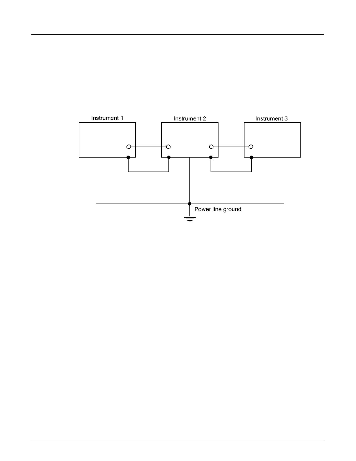
The following figure shows how to connect several instruments together to eliminate this ground loop
problem. Here, only one instrument is connected t o the power line ground. Ground loops are not
typically a problem with instruments with isolated LO terminals. However, all instruments in the test
setup may not have isolated terminals. When in doubt , consult the manual for each instrument in the
test setup.
Keeping connectors clean
As is the case with any high-resistance device, the integrity of connectors can be compromised if they
are not handled properly. If the connector insulati on becomes contaminated, insulation resistance will
be substantially reduced, affecting high-impedance measurement paths. Oils and salts from th e skin
can contaminate connector insulators, reducing their resistance. Also, contaminants present in the ai r
can be deposited on the insulator surface. To av oi d these problems, never touch the connector
insulating material. In addition, the scanner card should be used only in clean, dry environments to
avoid contamination.
If the connector insulators should become contami nated, either by inadvertent touching, or from
airborne deposits, they can be cleaned with a cotton sw ab di pped in clean methanol. After thoroughly
cleaning, they should be allowed to dry for several hours in a low-humidity environment before use, or
they can be dried more quickly using dry nitrogen.
3-20 2000-SCAN-900-01 Rev. A / April 2018
Page 43

All Keithley trademarks and trade names are the property of Keithley Instruments.
All other trademarks and trade names are the property of their respective companies.
Specifications are subject to change without notice.
Corporate Headquarters • 28775 Aurora Road • Cleveland, Ohio 44139 • 440-248-0400 • Fax: 440-248-6168 • 1-800-935-5595 • www.tek.com/keithley
Keithley Instruments
12/17
 Loading...