

Page 1
Astra-Z-8845 Ver. A
Wireless Repeater / Router
Operation Manual
Revision 8845-аv2_6_en
This operation manual is intended for studying the operating
principles, proper use, storage, and maintenance of the
Wireless Repeater / Router Astra-Z-8845 version A
(hereinafter referred to as router) (Figure 1).
The manufacturer reserves the right to make alteration regarding
refinement of the product without prior notification. All
improvements are included in new revision of the operation
manual.
List of Abbreviations:
Astra-Zitadel System: Astra-Zitadel on-site Wireless Intrusion
/ Fire Detection and Alarm System;
Astra-Zitadel System Control Panel – Astra-Z-812M, Astra-
Z-8945 ver.A, Astra-8945 Pro, Astra-712 Pro or Astra-812 Pro
Control Panel (with connected WE-2.4 Wireless Extender);
MSS Astra-Z – Astra-Z Monitoring Software Suite;
MSS Astra Pro: Astra Pro Monitoring Software Suite;
LT: Astra-942 Laser Tester;
BAT: Battery;
AL: Alarm Loop;
FW: Firmware;
MSS: Astra-Z Monitoring Software Suite.
1 Function
1.1 The router is intended for operation
within the Astra-Zitadel system.
1.2 The router is intended:
- for retransmitting messages (notifications,
control commands, responses, handshakes,
etc.) from wireless devices within the AstraZitadel system through all retransmission
levels to the control panel;
- for automatically routing messages from wireless devices if
the current data transfer route is lost;
- for controlling external devices (sirens, lighted signs) via its
outputs.
1.3 The router ensures operation directly with 30 detectors
(plus two mobile devices).
1.4 The router ensures TM identifier code transmitting to
control panel via radio.
1.5 The router ensures control of passive detectors and other
devices with «dry contact»-type outputs through the ZoneGND input with current control.
1.6 Power is supplied to the router from a 10-27 V power
supply unit.
1.7 The router has the potential to connect a backup power
supply unit: a lithium ion polymer rechargeable battery
(hereinafter BAT) of LP704374 type with nominal voltage of
3.7 V and a capacitance of 2 200 mA/h.
2 Specification
Technical Parameters of Radio Channel
Operating frequency range, MHz ..................... 2 400 to 2 483, 5
Number of operating channels at 5 MHz intervals ................... 16
Channel width, MHz .................................................................. 2
Wireless coverage range, line-of-sight, m, min ................... 1000
Relay 1 Technical Parameters
Loading voltage, V, max ........................................................ 100
Loading current, mA, max ..................................................... 150
AL Technical Parameters
Zone-GND terminal voltage
in standby mode, V ....................................................... 2,7 to 5,0
Zone-GND terminal
active ripple voltage, mV, max ................................................. 50
AL resistance*, kΩ
- in «Normal» status .................................................... 3,0 to 5,0
- in «Violation» status .............................................. <3,0 or >5,0
General Technical Parameters
Main power supply voltage, V ................................ from 10 to 27
Current consumption
(at a power supply voltage of 10 V), mA, max:
- in transmitting mode, without BAT, registered in
wireless network .................................................................... 135
- in transmitting mode, with charging BAT,
registered in wireless network ............................................... 170
BAT-powered supply voltage, V .............................. from 3 to 4,2
BAT-powered** operating time, h, min .................................... 24
BAT discharge notification threshold, V ........................... 3,5±0,1
Completely discharged battery charge
time, h, max ............................................................................. 24
Technical readiness time, s, max ............................................ 20
Overall dimensions, mm, max ................................... 1016332
Weight (without BAT***), kg, max ....................................... 0.065
Operating Conditions
Temperature range, °C ................................................ -30 to +50
Relative air humidity, % .................................. up to 95 at +35 °C
without moisture condensation
______________________________________________
* The permissible parameter spread for resistance is no more than 10%.
** At temperatures below 0 °C, the BAT-powered operating time is
significantly less.
*** BAT weight = 0.044 kg
3 Delivery Set
Router delivery package contents:
Astra-Z-8845 version A ...................................................... 1 pcs.
Screw 2.9×25 ................................ ................................ .... 4 pcs.
Dowel 5×25 ....................................................................... 4 pcs.
Operation Manual ............................................................. 1 copy
Note – BAT is supplied separately.
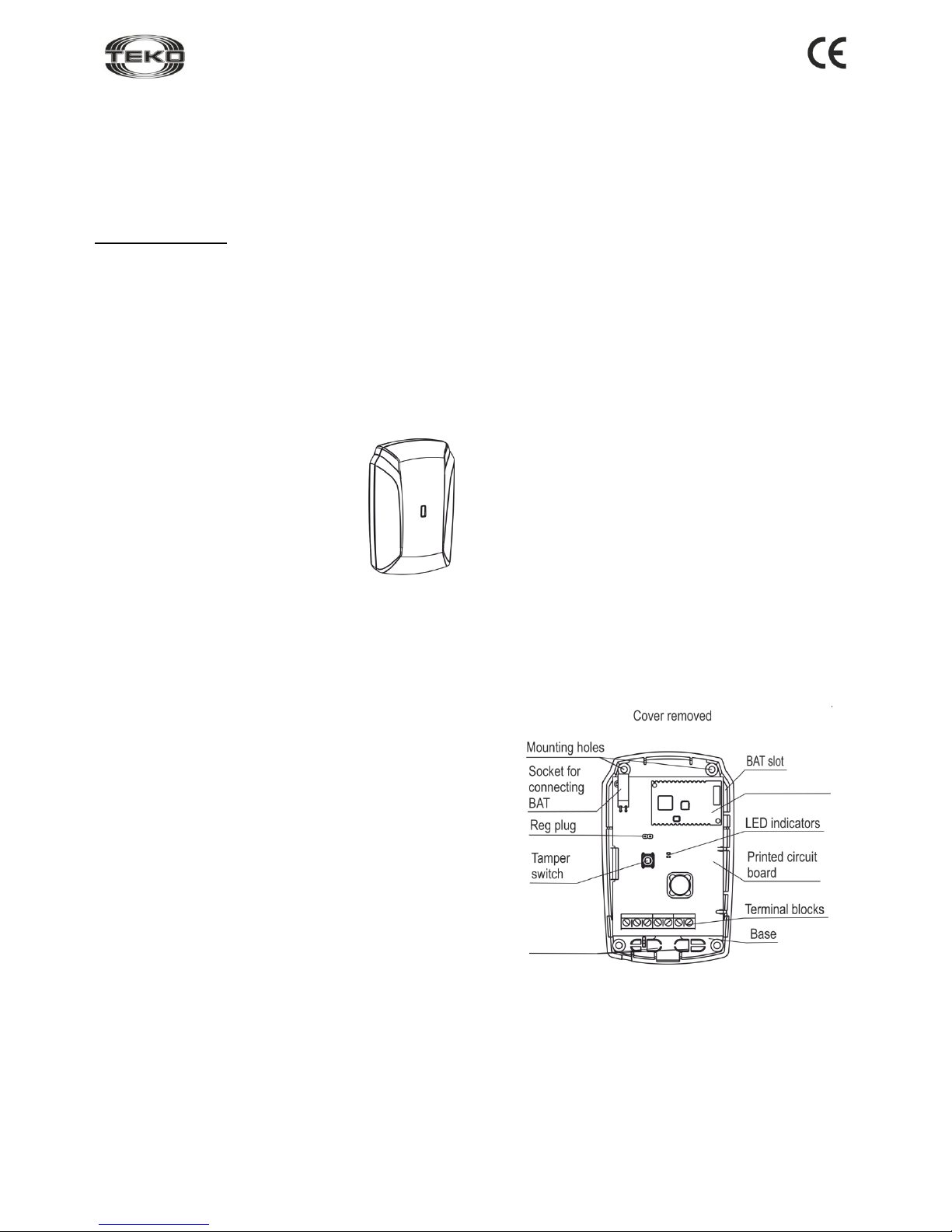
4 Structure
4.1 Structurally the router is designed as a block consisting of a
base and removable cover. Mounted inside the block is a printed
circuit board (PCB) with radio elements (Figure 2).
Figure 2
4.2 The base has a slot for installing BAT. The PCB has a
socket for connecting BAT outputs.
4.3 Mounted on PCB are red and white LEDs for router’s
functional status and the wireless network status supervision
respectively.
4.4 Mounted on PCB is a tamper switch, which results in the
«Tampering» notification when the cover is removed.
4.5 Mounted on PCB is a terminal block. For terminal function
see Table 1.
Figure 1
Radio module
Wire
insertion
holes
Page 2
Revision 8845-аv2_6_en
2
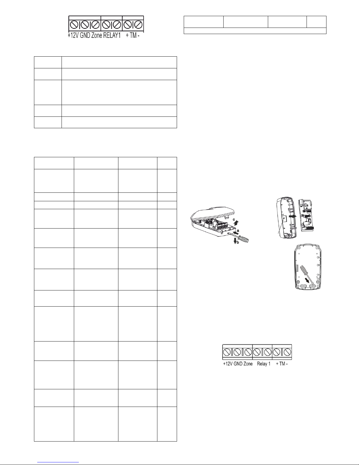
Table 1: Terminals
Terminal
Name
Terminal function and characteristics
+12V,
GND
Input for power supply connecting
GND,
Zone
AL Input with current control for external devices
with «dry contact» outputs connecting.
Wire length must be not greater than 10 m.
RELAY1
Output for slave devices connecting
+ТМ -
Not used in this router version
5 Notification Types
Table 2: Notifications to LEDs and Control Panel (or MSS
interface)
Notification
Type
Red
LED
White
LED
Control
Panel
Standby
mode start
Lights up one
time for 1 to 20
seconds after
powering up on
Not lit
-
Normal
Not lit
Not lit
+
AL normal
Not lit
Not lit
+
Violation
Lights up one
time for 0.2
seconds
Not lit
+
AL recovery
Lights up one
time for 0.2
seconds
Not lit
-
BAT discharge
Triple blink
every 25 seconds
Not lit
+
Main power
supply
failure
Not lit
Not lit
+
BAT failure
Not lit
Not lit
+
BAT
missing
Blinks with
frequency of 5
Hz during 5 sec.
after 5 sec of
detecting the
missing
Not lit
+
Tampering/
Tamper
recovery
Lights up one
time for 0.2
seconds
Not lit
+
Network
search
Not lit
Blinks with
frequency of 5
Hz for 1 to 60
seconds
-
No network
Not lit
Double blink
every 25
seconds
-
Command
received from
LT
Lights up one
time for 2
seconds upon
receipt of
command from
any LT button
-
-
Notification
Type
Red
LED
White
LED
Control
Panel
+: notification issued; –: notification not issued
6 Operating Modes
6.1 The router operating modes are defined via radio upon a
command from the control panel in accordance with an
appropriate Astra-Zitadel Quick Start Guide* or MSS
interface*.
1) switching AL supervision ON/OFF;
2) switching TM input (from MSS Astra-Pro only);
3) setting RELAY1 output operating mode;
4) FW upgrade.
6.2 Operating modes initiated by the Astra-942 laser tester
buttons:
1) test (upper button);
2) wireless network optimization (middle button);
3) router registration in wireless network (lower button).
7 Pre-Starting Procedure
7.1 After transportation in conditions differing from those of
operation, the router must be kept unpacked for 4 hours in the
expected operating conditions.
7.2 Running Router
Step-1
Push the cover catch out of
the base groove. Remove
the cover.
Step-2
Unbend the latch on the base.
Remove PCB.
Step-3
Push the blank out of the wire insertion hole
in the base.
Lead the wires from the power supply unit
through the hole.
Step-4
Insert BAT (if necessary) as follows:
a) Insert the BAT into the base;
b) Reinstall the PCB.
c) Connect BAT outputs to dedicated socket on the PCB.
Step-5
Connect wires from the power supply unit to the terminal
blocks in accordance with Table 1.
Supply power from an external source.
7.3 Registering the Router in the Wireless Network
Router registration is required for identification in the wireless
network in which it is supposed to operate.
Step-1 According to Astra-Zitadel System Control Panel`s
Operating Manual * perform the following procedure:
1) Install Software ** (MSS Astra-Z, Pconf-Z or MSS Astra
Pro) intended for configuring Control Panel.
2) Create wireless network
Step-2
Perform p.7.2.
Latch
Page 3

Revision 8845-аv2_6_en
3
Step-3
Switch the control panel to Wireless device registration
mode by the method described in the appropriate AstraZitadel System Control Panel`s Operating manual *.
The mode switches for 60 s.
Step-4
Initiate router registration procedure by one of 2 methods:
a) using LT (step-5);
b) using the Reg plug and the Tamper switch (step-6).
WARNING!
Avoid to initiate registration procedure on several
detectors simultaneously
Step-5
Initiating Router Registration Procedure Using LT (can
be conducted with router assembled):
1) Press the lower button on the LT and hold until a beam
appears.
2) Direct the laser beam at the router and irradiate LED for
at least 1 second.
The router’s red LED lights up for 2 seconds, and then the
white LED blinks with a frequency of 5 Hz for not more
than 60 seconds («Network search»).
Step-6
Initiating Router Registration
Procedure Using the Reg Plug and
Tamper Switch:
1) Shortly (for 0.5-2.5 seconds)
close the Reg plug with a
screwdriver.
The router switches to registration in
wireless network mode for 60
seconds.
2) Within 60 seconds, shortly press the tamper switch on
the router. The router switches to wireless network search
mode, at that white LED blinks at a frequency of 5 Hz.
Step-7
Verify registration procedure:
If registration procedure
completed successfully, the
abbreviated name of router
«RTR» appears on the screen or
«RTRxxx registered» notification
appears on the control panel`s
screen.
Assemble the router.
If registration procedure failed, repeat the registration
procedure, i.e. execute steps 3 and 5 or 3 and 6.
If registration procedure failed several times, perform
deletion of router from wireless network in accordance with
paragraph 7.4 and repeat registration procedure.
Step-8
Attention!
Do not switch off the router before the end of
registration and setting of all wireless devices in the
system.
After successful registration of the router, for long term
storage before its installation, it is allowed to switch the
router OFF.
When power is supplied, there is no need to re-register the
router in the same wireless network if it was not intentionally
removed from the network through MSS or control panel.
7.4 Deleting Router from Wireless Network
Deletion the router from wireless network is performed
using Software ** or through Control Panel`s menu.
When deleting detector from wireless network, Control Panel
transmits notification about deletion to detector within two
periods of RF supervision time. After receiving the notification
detector issues "No network" notification.
To speed up the deletion procedure:
- remove detector`s cover
- shortly close Reg plug
- press and hold down tamper switch for 8-10 sec.
The router issues "No network" notification to LED and is
available for registration.
7.5 Charging BAT
7.5.1 Prior to use, make sure that the BAT in the router is fully
activated via one charge/discharge cycle in the router. In order
to achieve this, charge the battery for at least 10 hours, fully
discharge it by disconnecting the external power supply unit for
at least 24 hours, and then recharge it for at least 24 hours.
7.5.2 It is permissible to begin using the router with partially
discharged BAT if a training cycle is conducted and the external
power supply voltage is guaranteed to be uninterrupted.
7.5.3 The BAT is recharged in the router from the DC power
source with a voltage of 10 to 27 V via the built-in smart
charger. Full charge of a fully discharged battery takes not more
than 24 hours.
8 Installation
8.1 Installation Procedure
Step-1
Push the cover catch out of
the base groove. Remove
the cover.
Step-2
Unbend the latch on the base.
Remove PCB and BAT (if
present).
Step-3
Push the blank out of the wire insertion and
mounting holes in the base.
Lead the wires from the power supply
unit and AL through the hole.
Step-4
Mark the selected
installation site using the
applied base.
Fasten the detector base.
Step-5
Insert the BAT by the method
given in p. 7.2. (if needed)
Replace the PCB.
Mounting holes
Latch
Page 4

Revision 8845-аv2_6_en
4
Step-6
Carry out wiring to the
router terminals in
accordance with Table 1.
Step-7
Replace the router cover
(until it clicks).
Step-8
Set the router operating modes in accordance with an
appropriate Astra-Zitadel system Quick Start Guide*.
Configure the router through «Alerting / System outputs»
menu sub-item.
Step-9
Verify Router Operability:
1) Verify the router status on the control panel or MSS
(«Normal» status should appear);
2) Initiate a test mode in accordance with an appropriate
Astra-Zitadel system Quick Start Guide*.
8.2 To ensure the alarm system reliable operation, testing
and maintenance of the router is recommended as follows:
- Inspect the integrity and secure fastening of the router
housing, external wires status and reliability of connection at
least once a month;
- Verify router operability by the method described in p.8.1 step
9 at least once a month;
- Clean contaminants from the router at least once in three
months.
9 Labeling
The following information is marked on the label attached to the router
housing:
- manufacturer trademark;
- abbreviated router designation;
- firmware version;
- month and year (last two digits) of manufacture;
- conformity mark (if an appropriate certificate is available);
- bar-code that duplicates textual information.
10 EC Conformity Declarations
This product is in conformity with the provisions of:
R&TTE Directive 1999/5/EC, Article 10.5;
EN 60950: 2001 Safety of information technology equipment;
EN 50371 Generic standard to demonstrate the compliance of lowpower electronic and electrical apparatuses with the basic restrictions
related to human exposure to electromagnetic fields (10 MHz - 300
GHz) – General public;
EN 301489-17 V1.1.1 (09-2000) Electromagnetic Compatibility and
radio spectrum Matters (ERM); Electromagnetic Compatibility (EMC)
standard for radio equipment and services; Part 17: Specific conditions
for wideband data Hiperlan equipment;
EN 300220-1 V1.3.1 (2000-09) Electromagnetic compatibility and
Radio spectrum Matters (ERM); Short range devices; Technical characteristics and test methods for radio equipment to be used in the 25
MHz to 1 000 MHz frequency range with power levels ranging up to
500 mW; Part 1: Parameters intended for regulatory purposes.
Construction of the detector provides for protection class IP41.
11 Recycling
11.1 The router poses no threat to human life, health or to the
environment; after its service life is over, it can be recycled without any
special environmental protection measures.
11.2 Recycle BAT by giving spent BAT to a trade organization, service
center, equipment manufacturer, or organization that accepts spent
batteries.
12 Warranty Terms
12.1 Quality Management System meets provisions of ISO 9001-2011.
12.2 The manufacturer guarantees the compliance of the router to
specifications on condition that user observes required conditions of
transportation, storage, installation and operation.
12.3 The storage warranty period is 5 years and 6 months from the date
of manufacture.
12.4 The operating warranty period is 5 years from the startup date, but
not more than 5 years and 6 months from the date of manufacture.
12.5 The manufacturer guarantees replacement or repair of the product
during the warranty period.
12.6 The warranty doesn’t come into effect in the following cases:
- not adherence to the operating manual;
- mechanical damage to the router;
- repair of the router by any third-party service except the
Manufacturer.
12.7 The warranty applies to the router only. All equipment from other
manufacturers used in conjunction with the router is subject to its own
warranty terms.
The manufacturer bears no responsibility for death, injury,
property damage or other incidental or premeditated loss based
on user's statement that the device failed to implement its
functions.
* Available for free downloading from www.controlex.eu
Sales:
Controlex GmbH
Warranty service and
technical support:
ТЕКО-TD
Philosophenweg 31-33
47051 Duisburg, Germany
Phone: +49 (0) 203 / 393 91 188
Fax: +49 (0) 203 / 393 91 189
GSM: +49 (0) 178 / 218 48 22
E-mail: info@controlex.eu
Web: www.controlex.eu
Prospekt Pobedy str. 19
420138 Kazan, Russia
Phone: +7 (843) 261-55-75
Fax: +7 (843) 261-58-08
E-mail: info@teko.biz
support@teko.biz
Web: www.teko.biz
Made in Russia
 Loading...