

Page 1
Astra-Z-3645
Wireless Electro-Contact Water Leak Detector
Operating Manual
This operation manual is intended for studying the operating principles,
proper use, storage, and maintenance of Wireless Electro-Contact
Water Leak Detector Astra-Z-3645 (hereinafter “detector”) (Fig. 1).
The manufacturer reserves the right to introduce changes which update and retrofit the detector without prior notice. All such changes will
be described in an updated revision of the operating manual.
List of Abbreviations:
Astra-Zitadel system –on-site Wireless Intrusion / Fire Detection and
Alarming System Astra-Zitadel;
Astra-Zitadel System Control Panel: Astra-Z-812M, Astra-Z-8945
ver.A, Astra-8945 Pro or Astra-812 Pro Control Panel (with connected
Astra-Z Wireless Extender);
MSS Astra-Z – Monitoring Software Suite Astra-Z;
MSS Astra Pro – Monitoring Software Suite Astra Pro;
LT – Laser Tester Astra-942;
Battery – power supply battery.
1 Function
1.1 The detector generates and sends to the
control panel “Alarm” notifications when water of any
chemical composition (except for distilled water) gets
to detector contact pads.
1.2 The detector is powered by one battery of
CR2450 type (voltage – 3.0 V) (included in the delivery set).
2 Specifications
Technical Parameters of Wireless Channel
Bandwidth, MHz ........................................................... 2400 to 2483.5
Number of active channels with 5 MHz increment ............................ 16
Channel width, MHz ........................................................................... 2
Wireless coverage range, line-of-sight, m, min ............................... 300
General parameters
Power supply voltage, V .............................................................. 2.2-3
Current consumption, mA, max:
- radio module ON ........................................................................... 45
- radio module OFF ..................................................................... 0,010
Battery replacement indication threshold, V ................................ 2.5
-0.2
Power supply voltage lower threshold (deactivating
threshold retaining battery discharge indication), V ......... below (2.3
-0.2
)
Battery service life, months, min ...................................................... 18
Overall dimensions, mm, max .............................................. 644622
Weight (with battery), kg, max ..................................................... 0.074
Operating Conditions
Temperature range, °С .......................................... from + 5 up to + 50
Relative air humidity, % .......................................... up to 95 at +35 °С
no moisture condensation
3 Delivery Set
Astra-Z-3645 ............................................................................. 1 pcs.
Battery ....................................................................................... 1 pcs.
Operating Manual .................................................................... 1 copy.
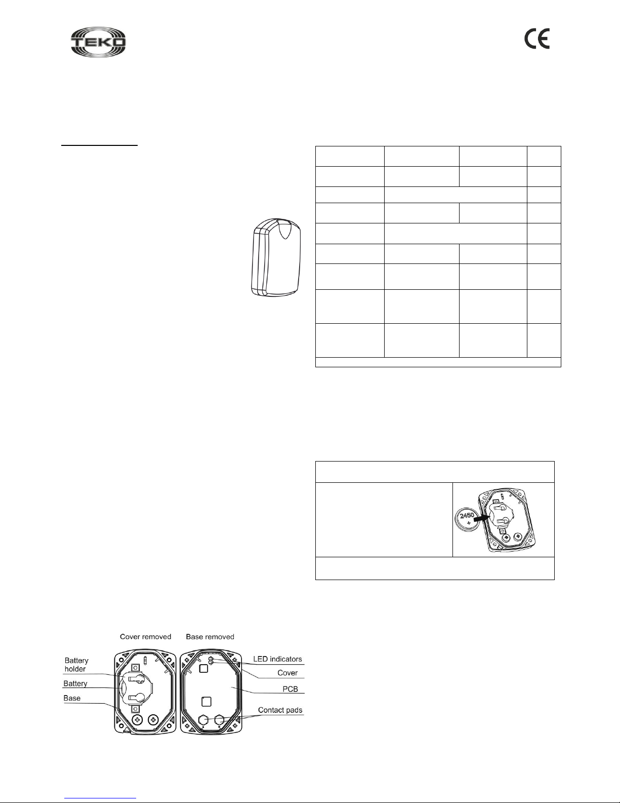
4 Structure
4.1 The detector is designed as a unit consisting of a removable
cover, a base and a printed circuit board with radio elements (Fig. 2),
the battery from the delivery set is pre-installed.
Fig. 2
4.2 The following indicators are mounted on the printed circuit board:
red – for detector operability supervision, white – for wireless network
status indication.
5 Information Capacity
Table 1 – Notification – Detector indicators and control panel
Notification
type
Red
indicator
White
indicator
Control
panel
Detector standby
mode start
Lights up once for
1 s after power up
−
−
Norm
Not lit
+
Violation
Lights up once for
0.2 s
−
+
Power ON
Not lit
+
Power failure
Blinks 3 times every
25 s
−
+
Network search
−
Blinks 5 times a
second for 1 to
60 s
−
No network
−
Blinks 2 times
every 25 s
−
Radio module
failure
−
Blinks 3 times
every 25 s
+
“+” – the notification is given, “–” – the notification is not given
Note – When “Power failure” notification is given, replace the battery
within two months.
6 Pre-Starting Procedure
6.1 After transportation in conditions differing from those of operation,
the detector must be kept unpacked for at least 4 hours in the operating conditions.
6.2 Running Detector. Battery Replacement
Step-1
Remove the detector cover by unscrewing 4 screws from the base side
Step-2
Install the battery (to replace, remove
the old battery, wait at least 2 min and
install the new one).
The red indicator lights up for 1 s (if
after 60 s the red indicator blinks 3
times every 25 s, the battery is
discharged and must be replaced).
Step-3
Close the detector cover by screwing 4 screws from the base side
6.3 Registering the Detector in the Wireless Network
Detector registration is required for detector identification in the wireless network in which it shall operate.
Step-1
According to Astra-Zitadel System Control Panel`s Operating
Manual * perform the following procedure:
1) Install Software ** (MSS Astra-Z, Pconf-Z or MSS Astra Pro)
intended for configuring Control Panel;
2) Create wireless network.
Step-2
Perform p. 6.2
Step-3
Switch the control panel to Wireless device registration mode by
the method described in the appropriate Astra-Zitadel System
Control Panel`s Operating manual *.
The mode activates for 60 s for registration of 1 wireless device.
Fig. 1
Page 2

Rev. 3645-v1_5_en
2
Step-4
Initiate detector registration procedure by one of 2 methods:
а) using LT (step 5);
b) by closing contact pads (step 6).
Step-5
Initiating Detector Registration Procedure Using LT:
1) press the lower LT button and wait until the beam appears;
3) shine the laser beam on the detector indicator from a distance of
not more than 5 m (detector cover is removed);
4) illuminate the indicator for 1 s.
The detector`s red LED lights up for 2 seconds, then the detector
switches to wireless network search mode and the white LED
blinks at a frequency of 5 Hz.
Step-6
Initiating Detector Registration by
closing (shorting) contact pads:
1) Using a screwdriver, shortly (for 1-2
s) close the detector contact pads.
The “Waiting for detector registration in
the network” mode switches ON for 60 s.
2) Close the detector contact pads
again (for not more than 2 s).
The detector switches to the wireless network search mode, and its
white indicator blinks 5 times per second.
Step-7
Verify registration procedure:
Once registration procedure completed successfully, the
abbreviated name of detector «WLD» appears on the screen or
«WLDxxx registered» notification appears on the control panel`s
screen.
Once registration procedure failed, repeat the registration
procedure, i.e. perform steps 3, 5 or 3, 6.
Step-8
After successful registration of the detector, for long term storage
before its installation, it is allowed to switch the detector OFF by
removing the battery or installing a soft isolator.
When power is supplied, there is no need to re-register the detector in
the same wireless network if it was not intentionally removed from the
network through software or control panel.
6.4 Deleting Alerter from Wireless Network
Deletion the detector from wireless network is performed using
Software ** or through Control Panel`s menu.
When deleting detector from wireless network, Control Panel transmits
notification about deletion to detector within two periods of RF
supervision time. After receiving the notification detector issues "No
network" notification.
To speed up the deletion procedure:
- close shortly detector`s contact pads
- within 1 minute close and hold closed for 8-10 sec. contact pads
The detector issues "No network" notification to LED and is available
for registration.
7 Installation
7.2 The detector shall be mounted on the floor in the lowest place of
a room where flooding possibility is monitored (taking into account
directions of water flow in case of burst water conduits or heating
system pipelines).
7.3 The detector shall be mounted with the contact pads facing
downwards.
7.4 Check detector operability:
- close the contacts pads (e.g., with a wet cloth),
- make sure “Violation” event is displayed on the display of Astra-Z-
812М or MSS Astra-Z.
8 Maintenance
To provide for reliable operation of the detector it is recommended to
test and maintain the detector at least once a month in the following
way:
- inspect integrity of the detector body;
- check its location;
- check detector operability as described in 7.3;
- clean the detector from any dirt accumulated.
9 Labeling
The following data are shown on the label glued to the body:
- manufacturer trademark;
- detector abbreviated designation;
- firmware version;
- month and year of manufacture (last two digits);
- conformity mark (if the conformity certificate is available);
- bar code, duplicating textual data.
10 EC Conformity Declarations
This product is in conformity with the provisions of:
R&TTE Directive 1999/5/EC, Article 10.5;
EN 60950: 2001 Safety of information technology equipment;
EN 50371 Generic standard to demonstrate the compliance of lowpower electronic and electrical apparatuses with the basic restrictions
related to human exposure to electromagnetic fields (10 MHz - 300
GHz) – General public;
EN 301489-17 V1.1.1 (09-2000) Electromagnetic Compatibility and
radio spectrum Matters (ERM); Electromagnetic Compatibility (EMC)
standard for radio equipment and services; Part 17: Specific conditions for wideband data Hiperlan equipment;
EN 300220-1 V1.3.1 (2000-09) Electromagnetic compatibility and
Radio spectrum Matters (ERM); Short range devices; Technical characteristics and test methods for radio equipment to be used in the 25
MHz to 1 000 MHz frequency range with power levels ranging up to
500 mW; Part 1: Parameters intended for regulatory purposes.
Construction of the detector provides for protection class IP41.
11 Recycling
11.1 Detector is not a danger to life, human health and the
environment. On expiry of its lifetime recycling is done without taking
special measures to protect the environment.
11.2 Recycling of battery cells should be done by delivering used cells
to a trading organization, service centre, manufacturer, or to an organization accepting used batteries.
12 Manufacturer Warranties
12.1 Quality Management System meets provisions of ISO 9001-2011.
12.2 The manufacturer guarantees the compliance of the detector to
specifications on condition that user observes required conditions of
transportation, storage, installation and operation.
12.3 The storage warranty period is 5 year and 6 months from the date
of manufacture.
12.4 The operating warranty period is 5 year from the date of commissioning, but not more than 5 year and 6 months from the date of manufacture.
12.5 The manufacturer shall repair or replace a faulty detector during
the warranty period.
12.6 The warranty becomes void if:
- the user does not follow guidelines of the operating manual;
- the detector is mechanically damaged;
- the detector is repaired by a party other than the Manufacturer.
12.7 The warranty covers the detector only. All equipment manufactured by other parties and used with the detector, including batteries, is
covered by its respective warranty.
The manufacturer bears no responsibility for death, injury, property damage or other incidental or premeditated loss based on
user's statement that the device failed to implement its functions.
* Available for free downloading from www.controlex.eu
and/or integrated with configuring software.
** Available for free downloading from www.controlex.eu.
Sales:
Controlex GmbH
Warranty service and
technical support:
ТЕКО-TD
Philosophenweg 31-33
47051 Duisburg, Germany
Phone: +49 (0) 203 / 393 91 188
Fax: +49 (0) 203 / 393 91 189
GSM: +49 (0) 178 / 218 48 22
E-mail: info@controlex.eu
Web: www.controlex.eu
Prospekt Pobedy str. 19
420138 Kazan, Russia
Phone: +7 (843) 261-55-75
Fax: +7 (843) 261-58-08
E-mail: info@teko.biz
support@teko.biz
Web: www.teko.biz
Made in Russia
 Loading...