

Teknatool Nova Viking Series, Nova 83701, Nova 83700, Nova 83703, Nova 83702 Operation Manual
...
123-0719-018
OPERATION MANUA
L
Viking DVR 16”
Benchtop Drill Press
™
Publication: 123-0719-018
Date: 11 July 2019
Models:
83700 - USA
83701 - NZ/Australia
83702 - Canada
83703 - Europe
83704 - UK

123-0719-018
Contact
Teknatool International Ltd
Phone: (+64) 9 477 5600
Teknatool USA
Phone: 727-954-3433
Customer Solutions
For all worldwide Inquiries, Repairs or Services (issues must be in writing)
Email: Service@Teknatool.com
Or you can contact the retailer where you purchased your NOVA Viking DVR Drill Press, for the contact
details please see our website www.teknatool.com

123-0719-018
Table of Contents
Contact .................................................................................................................................................................................... 2
Table of Contents .................................................................................................................................................................... 3
General Safety Rules ............................................................................................................................................................... 5
Additional Safety Rules for Drill Presses ................................................................................................................................. 6
NOVA DVR Viking Features ..................................................................................................................................................... 1
Drill Press Features ............................................................................................................................................................. 1
Drill Press Specifications ..................................................................................................................................................... 2
Package Contents .................................................................................................................................................................... 3
Assembling the Drill Press ....................................................................................................................................................... 4
Drill Press Body ................................................................................................................................................................... 4
Drill Chuck and Arbor .......................................................................................................................................................... 4
Drill Press Handle ................................................................................................................................................................ 5
Chuck and Arbor Assembly Attachment ............................................................................................................................. 5
Attaching the Drill Press Table ............................................................................................................................................ 6
Tilting the table ............................................................................................................................................................... 6
Attaching the Chuck Guard ................................................................................................................................................. 7
Connecting to Power ............................................................................................................................................................... 8
Ground Fault Interrupters (GFI) ...................................................................................................................................... 9
Setting up your drill press ....................................................................................................................................................... 9
Setting up your workshop environment ............................................................................................................................. 9
Drill Press Interface ............................................................................................................................................................... 10
Keypad Buttons ................................................................................................................................................................. 10
Display Icons ..................................................................................................................................................................... 10
Operating the Drill Press ....................................................................................................................................................... 12
Turning the Drill Press ON ................................................................................................................................................. 12
Basic Drill Press Functions ................................................................................................................................................. 12
Running the drill press .................................................................................................................................................. 12
Stopping the drill press ................................................................................................................................................. 13
Emergency Stop ............................................................................................................................................................ 13
Adjusting the speed ...................................................................................................................................................... 13
Changing the display mode ........................................................................................................................................... 14
Changing the measurement units ................................................................................................................................. 14
Switching between forward and reverse ...................................................................................................................... 15
Zeroing the depth ......................................................................................................................................................... 16

123-0719-018
Using the light and lasers .............................................................................................................................................. 17
Intermediate Functions ..................................................................................................................................................... 18
Using the electronic depth stop function ..................................................................................................................... 18
Quick Set Depth Function ............................................................................................................................................. 19
Electronic Depth Stop Function .................................................................................................................................... 19
Using the Self-Start Function ........................................................................................................................................ 20
Power Spindle Hold Function ........................................................................................................................................ 21
Advanced Functions .......................................................................................................................................................... 22
Performing a Factory Reset ........................................................................................................................................... 22
Turning the sound on or off .......................................................................................................................................... 22
Changing the power bar settings .................................................................................................................................. 23
Calibrating the Height Sensor Drill Press ...................................................................................................................... 24
Unlocking the drill press speed range to 6000rpm ....................................................................................................... 24
Changing the drill press depth stop behaviour ............................................................................................................. 25
Maintaining your Drill Press .................................................................................................................................................. 26
Maintenance after each use ............................................................................................................................................. 26
Monthly maintenance ....................................................................................................................................................... 26
6month Maintenance ....................................................................................................................................................... 26
Speed Chart for Metal Drilling .............................................................................................................................................. 26
Full Speed Chart for General Materials ................................................................................................................................. 27
Firmware Update .................................................................................................................................................................. 28
Checking the firmware version ......................................................................................................................................... 28
USB Mode ......................................................................................................................................................................... 29
Troubleshooting .................................................................................................................................................................... 30
Mechanical Issue ............................................................................................................................................................... 30
Electrical Issues ................................................................................................................................................................. 32
Error Codes ....................................................................................................................................................................... 32
Teknatool Warranty .............................................................................................................................................................. 33
Viking Drill Press Headstock Breakdown .............................................................................................................................. 34
Viking Drill Press Stand and Base .......................................................................................................................................... 35
NOVA Viking Drill Press Parts List ......................................................................................................................................... 36
Chuck Guard .......................................................................................................................................................................... 39
Appendix ............................................................................................................................................................................... 40
NOVA Viking Wiring Diagram ............................................................................................................................................ 40
Using the included accessories ......................................................................................................................................... 41
Chuck Drift..................................................................................................................................................................... 41

123-0719-018
General Safety Rules
WARNING! Failure to follow these rules may result in serious personal injury or death.
IMPORTANT: Before switching the drill press on, ALWAYS check the machine for the correct setting and
speed, as well as ensuring the Chuck Key is removed.
1. FOR YOUR OWN SAFETY, READ THE MANUAL
BEFORE OPERATING THE TOOL. Learn the machine’s
application and limitations, plus the specific hazards
particular to it.
2. ALWAYS USE SAFETY GLASSES (must be ANSI
approved) Everyday eyeglasses usually are only impact
resistant and safety glasses only protect eyes. A full-face
shield will protect the eyes and face. Also use face or dust
mask if cutting operation is dusty.
3. WEAR PROPER APPAREL. Do not wear loose clothing,
gloves, neckties, rings, bracelets or other jewelry which
may get caught in moving parts. Nonslip footwear is
recommended. Wear protective hair covering to contain
long hair.
4. USE EAR PROTECTORS. Use ear muffs for extended
period of operation. Use muffs rated to 103 DBA LEQ (8
hour).
5. DON’T USE IN DANGEROUS ENVIRONMENT. Don’t
use power tools in damp or wet locations, or expose them
to rain. Keep work area well lighted. The NOVA Viking
DVR Drill press is intended for indoor use only. Failure to
do so may void the warranty.
14. KEEP GUARDS IN PLACE and in working order.
15. USE CORRECT TOOLS. Do not use a tool or attachment to
do a job for which it was not designed.
16. USE RECOMMENDED ACCESSORIES. The use of
improper accessories may cause hazards.
17. DON’T FORCE THE TOOL. It will do the job better and be
safer at the rate for which it was designed.
18. MAINTAIN TOOLS IN TOP CONDITION. Keep tools sharp
and clean for best and safest performance. Follow
instructions for lubricating and changing accessories.
19. NEVER STAND ON TOOL. Serious injury could occur if the
tool is tipped or if the cutting tool is accidentally contacted.
20. REMOVE ADJUSTING KEYS AND WRENCHES. Form a
habit of checking to see that keys and adjusting wrenches
are removed from tool before turning it on.
21. DON’T OVERREACH. Keep proper footing and balance at
all times.
22. DIRECTION OF FEED. Feed work into a blade or cutter
against the direction of rotation of the blade or cutter only.
23. PAY ATTENTION TO WORK. Concentrate on your work. If
you become tired or frustrated, leave it for a while and rest.
24. SECURE WORK. Use clamps or a vice to hold work when
practical. Severe injury or death can occur if an object comes
free as it can become a dangerous projectile.
25. CHECK DAMAGED PARTS. Before further use of the tool,
any part that is damaged should be carefully checked to
ensure that it will operate properly and perform its intended
function. Check for alignment of moving parts, binding of
moving parts, mounting, and any other conditions that may
affect its operation. Any damaged part should be properly
repaired or replaced.
26. DRUGS, ALCOHOL, MEDICATION. Do not operate
machine while under the influence of drugs, alcohol, or any
medication.
27. DUST WARNING. The dust generated by certain woods
and wood products can be harmful to your health. Always
operate machinery in well-ventilated areas and provide
means for proper dust removal. Use wood dust collection
systems whenever possible.
28. DO NOT MODIFY OR USE DRILL PRESS FOR USES
OTHER THAN FOR WHICH IT WAS DESIGNED.
6. KEEP WORK AREA CLEAN. Cluttered areas and benches
invite accidents. Build-up of sawdust is a fire hazard.
7. KEEP CHILDREN AND VISITORS AWAY. The Nova
Viking DVR is not recommended for children and infirm
persons. Such personnel and onlookers should be kept a
safe distance from work area.
8. MAKE WORKSHOP CHILDPROOF with locks, master
switches, or by removing starter keys.
9. GROUND ALL TOOLS. If the tool is equipped with a
three-prong plug, it should be plugged into a three-hole
electrical receptacle. If an adapter is used to
accommodate a two-prong receptacle, the adapter plug
must be attached to a known ground. Never remove the
third prong.
10. MAKE SURE TOOL IS DISCONNECTED FROM POWER
SUPPLY while the motor is being mounted, connected,
or reconnected.
11. DISCONNECT TOOLS FROM WALL SOCKET before
servicing and when changing accessories such as bits,
cutters and fuses etc.
12. AVOID ACCIDENTAL STARTING. Make sure switch is in
the “Off” position before plugging in power cord.
13. NEVER LEAVE MACHINE RUNNING UNATTENDED.
Do not leave machine unless it is turned off and has come
to a complete stop

123-0719-018
Additional Safety Rules for Drill Presses
WARNING! Failure to follow these rules may result in serious personal injury.
1. SEEK INSTRUCTION. If you are not thoroughly familiar
with the operation of drill press, obtain advice from your
supervisor, instructor, or other qualified person.
Instruction from a qualified person is strongly
recommended.
2. DO NOT OPERATE DRILL PRESS until it is completely
assembled and installed. Follow instructions and
recommendations.
3. FOLLOW ELECTRICAL CODES. Make sure wiring codes
and recommended electrical connections are followed
and that the machine is properly grounded.
4. WHEN REPLACING THE FUSE (on relevant models),
completely isolate power when removing the fuse. It is
imperative the plug is removed from the power supply
before the fuse is removed. Replace fuse cap before
reconnecting to power.
5. DO NOT OPEN THE SWITCH AND REAR COVERS.
Components can carry dangerous voltages even when
isolated from mains power.
6. KEEP WORK AREA CLEAN. Do not turn the drill press
on before clearing the drill press of all objects (tools,
scraps of wood, etc.). Keep the nearby area and floor clear
of debris.
7. CHECK SET-UP with spindle off. Examine the set-up
carefully and rotate the work piece by hand to check
clearance and check speed is correctly selected before
turning on spindle.
8. DO NOT MAKE ADJUSTMENTS when the drill press
spindle is turning. Make all adjustments with power OFF.
9. TIGHTEN ALL CLAMP HANDLES on the drill press before
operating drill press.
10. ALWAYS CHECK CORRECT SPEED IS SELECTED
BEFORE SWITCHING ON DRILL PRESS.
11. OPERATE AT RECOMMENDED SPEED. Always operate
the drill press at the recommended speeds. Consult the
built-in speed chart on the drill press for suggested
speeds.
12. DO NOT OPERATE DRILL PRESS IF DAMAGED OR
FAULTY. If any part of your drill press is missing, damaged
or broken, in any way, or any electrical component fails, shut
off the drill press and disconnect the drill press from the
power supply. Replace missing, damaged, or failed parts
before resuming operation.
13. ADDITIONAL SAFETY INFORMATION regarding the safe
and proper operation of this product is available from the
National Safety Council, 444 N. Michigan Avenue, Chicago,
IL 60611 in the Accident Prevention Manual of Industrial
Operations and also in the Safety Data Sheets provided by the
NSC. Also refer to the American National Standards Institute
ANSI 01.1 Safety Requirements for Woodworking Machines
and the U.S Department of Labor OSHA 1910.213 Regulation.
1
123-0719-018
NOVA DVR Viking Features
Drill Press Features
DIRECT DRIVE POWER
AND CONSISTENT
TORQUE
1HP DVR Smart Digital Motor delivers
correct speed, and power to maintain
optimal torque direct to the drill head,
across the entire speed range. No belts
or pulleys to cause vibration or power
loss.
A belt and pulley system
absorb typically 20% of the
motor power before it even
gets to the tool. The DVR
motor delivers constant
torque no matter what the
materials
SMART
DIGITAL
MOTOR
Smart sensors interacting in a
number of ways safety, intelligence
workshop assist, and performance
BUILT IN LASER
AND LIGHT
Quickly locate centre position with
the cross haired laser– laser stays
aligned even when table is moved or
tilted, and the DVR low/no vibration
performance means laser won’t move
in operation. Two powerful LED lights
to keep your project well lit.
CAST IRON
WOODWORKING
TABLE
Maximum flexibility and options for the
user. Solid Cast Iron for maximum
stability. Woodworking design to
provide maximum clamping and
accessory options
12 2/3″ x 12 2/3″ (320mm x
320mm). Tilting and
Rotating
ELECTRONIC
VARIABLE
SPEED
Versatile for a variety of projects – from
large deep hole drilling, mortising,
through to high speed sanding.
DISPLAY
Large, easy to read display with
imperial (fractions or decimal) or metric
provides choice with that the customer
prefers to use.
Easy to switch between modes.
FORWARD
AND REVERSE
For LH drill bits, gives the owner more
flexibility for projects.
ELECTRONIC
DEPTH STOP
Quickly and accurately automatically
stops to the precise depth you program
for your project.

2
123-0719-018
SELF-START
Enables a one-handed drilling
operation by automatically turning on
and off.
SPLIT MOTOR
(EXPOSED)
Easy access to motor. Much easier to
get serviced for both customers and
dealers.
BRAKING
E-stop
Drill Press Specifications
Drill Press Physical Specifications
Swing
16” (406.4mm)
Stroke
4.5” (114.3mm)
Spindle to Table
12 2/3” (321.73mm)
Spindle to Base
22 2/3” (575.73mm)
Drill Chuck
5/8” (2- 15.87mm)
Spindle Taper
2MT
Quill Diameter
60mm
Table Dimension
320 x 320mm
Base Dimension
468.7 x 270 x 55mm
Motor Specifications
Motor Type
DVR Direct Drive Smart Motor
Motor power output
1HP (0.75KW)
Maximum Speed
3000 RPM (6000 RPM when unlocked)
Input voltage
110V ~ 220V
Input Frequency
50/60 Hz
Input Current
15A (max)

3
123-0719-018
Package Contents
Item Number
Description
SKU
1
Viking Drill Press Body
8379001~8379008
2
Drill Press Base
8379025
3
Drill Press Table
8379022
4
Table Insert
8379024
5
Chuck Drift
8379067
6
Chuck Key
8379069
7
Drill Press Chuck
8379068
8
Chuck Arbor
8379019
9
Drill Press Handle (x3)
8379044
10
Table Arm Locking Handle (x2)
8379064
11
Table arm handle
8379028
12
Open end wrench
8379066
13
USB A-A cable
8379059
14
Chuck Guard Assembly
8379009
15
Chuck Key Holder
8379102
16
Allen Key Set
AK3, AK4, AK5
Note: The Chuck Guard Assembly is only included as standard for the EU model
4
123-0719-018
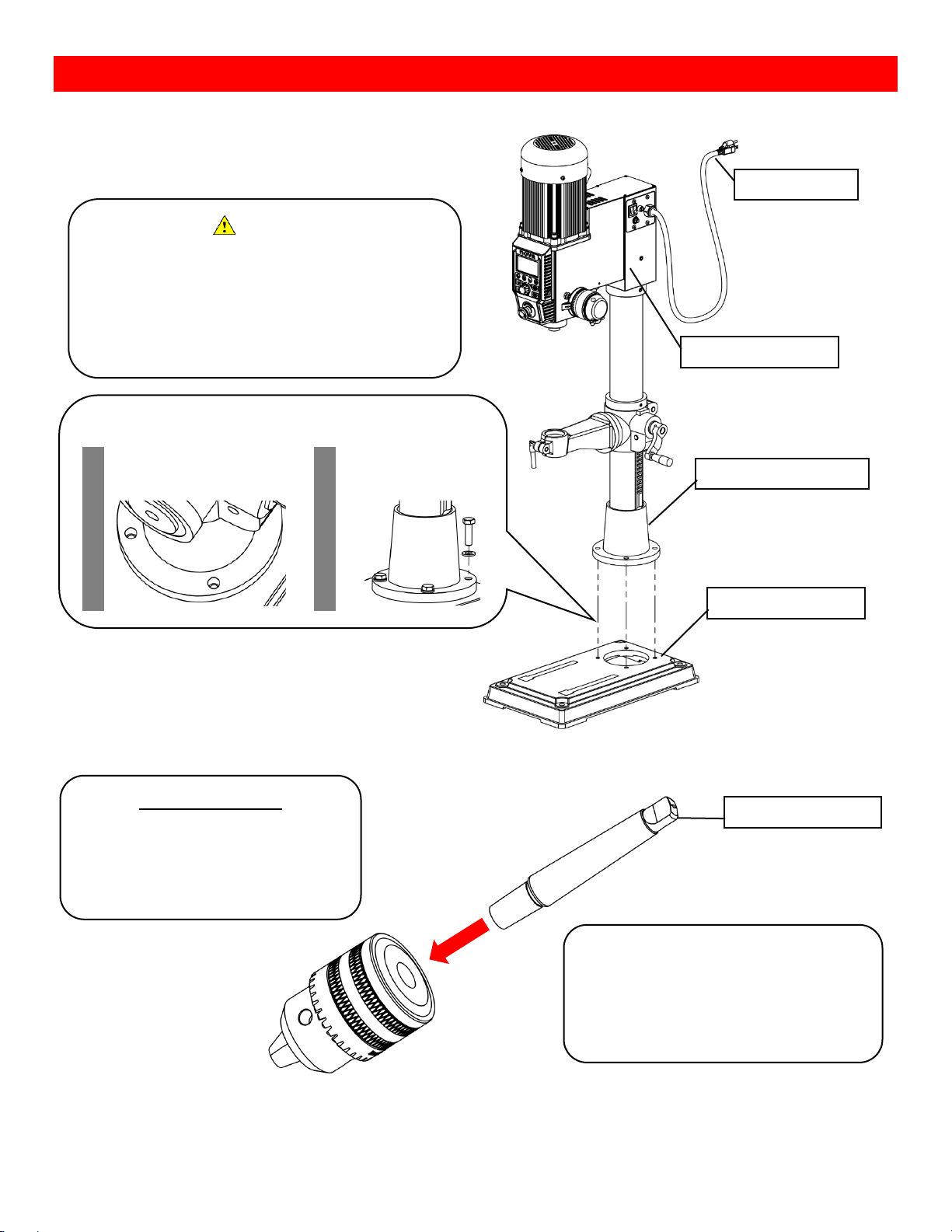
Assembling the Drill Press
Drill Press Body
The NOVA Viking drill press come with its headstock
preassembled with its main column.
Drill Chuck and Arbor
Caution
The headstock assembly can be
heavy and it is a subject to tip over.
It is recommended to have at
least 2 people when assembling
the drill press.
Drill press headstock
Power Cable
Drill press base
Attaching the drill press base
1. Align the thread holes
on the drill press base
and column base
2. Bolt the bases
together with the M10
bolt
Drill press column base
Before assembling
Wipe down all surfaces which makes
contact with other parts free of any dusts
or lubricants.
• Both long and short side of Arbor
• Tapered hole of the chuck
Arbor tongue
Insert the short end of the Arbor into the
drill chuck.
Secure the Arbor into the chuck by lightly
tapping the Arbor tongue with a rubber
mullet.

5
123-0719-018
Drill Press Handle
Chuck and Arbor Assembly Attachment
Screw drill press handles into the drill
press pinion shaft
Insert the arbor into the drill press
quill.
Note:
Make sure the arbor tongue is
facing the correct direction.
If the arbor is installed correctly,
the arbor should stay in the drill
press quill.
Give the chuck a few sharp taps
with a rubber mullet
Few sharp taps
with a rubber
mullet
6
123-0719-018
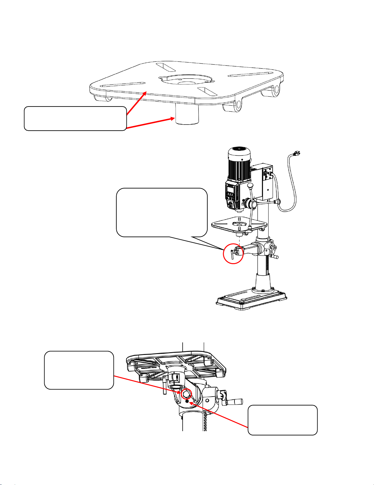
Attaching the Drill Press Table
Take the drill press table out from the packaging and inspect all surfaces for and defects (i.e. Stains, rusts,
fractures, scratches) on the machined cylindrical part of the table.
Insert the drill press table into the table arm.
Loosen the table arm lock if necessary.
Tilting the table
Loosen the main table bolt with a 24mm wrench and loosen the smaller grub screw with <Allen Key>.
Surfaces to check for cracks,
porosities and any defects
This handle is used to lock the
inserted table into place.
Loosen this handle if the table
cannot be inserted easily
1. Main hex bolt to
be loosened with
the included
24mm wrench
2. Grub screw to be
loosened with a
mm Allen key
7
123-0719-018
Lock the main table bolt first and then lock the secondary grub screw to secure the table position.
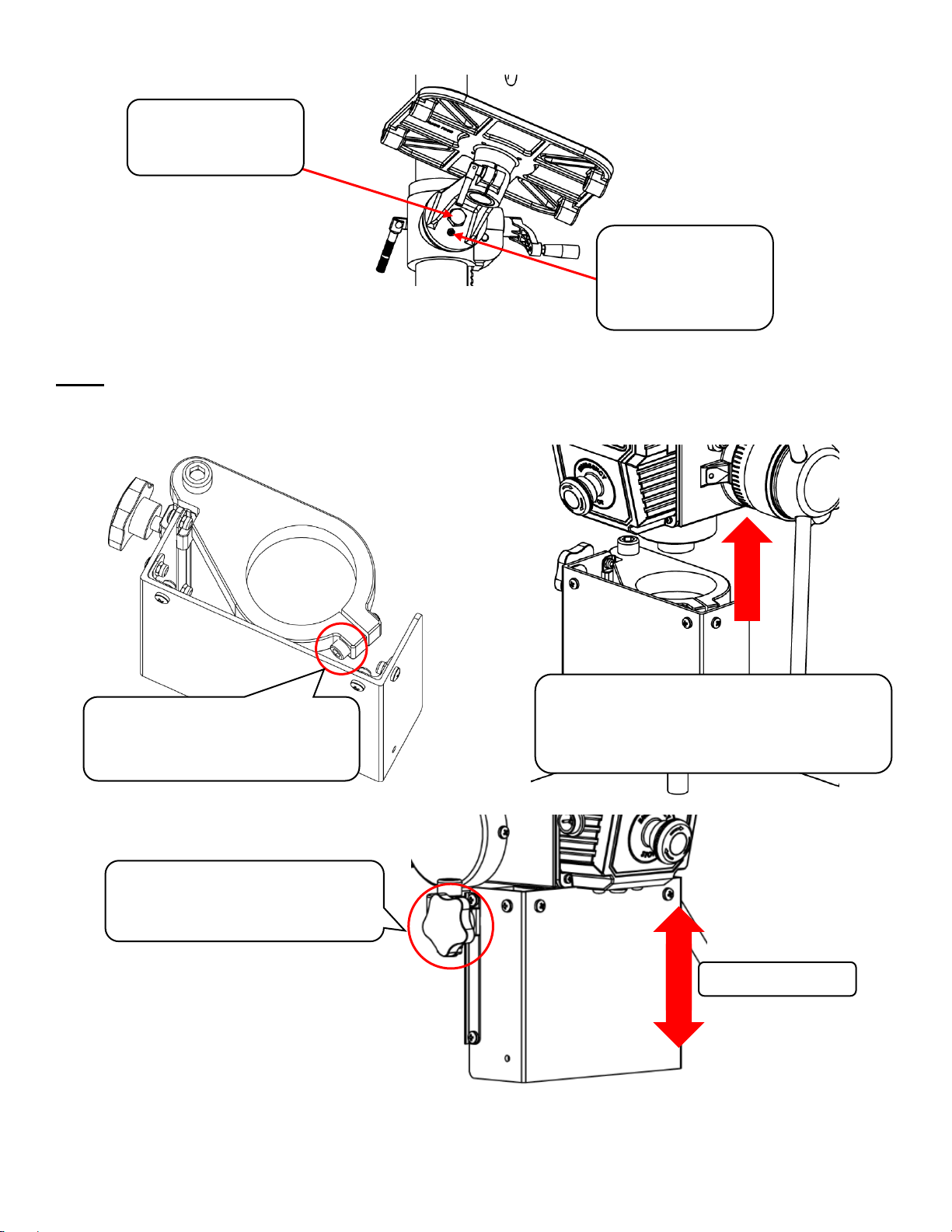
Attaching the Chuck Guard
Note: Only applicable to versions containing the chuck guards at default.
Take the chuck guard out from the packaging and peel off the protective sheet adhered to the guard. Inspect
for any defects on the guard.
Make sure to have the chuck guard covering the entire chuck.
Lock the main bolt
first after the table
angle has been set
Tighten the grub
screw on the bottom
after tightening the
main bolt.
Loosen the guard locking bolt
by hand or use a 5mm Allen
wrench.
Slide the guard over the drill press quill
and lock it into place by tightening the
guard locking bolt by using a 5mm Allen
wrench.
The vertical position of the
guard can be adjusted by
loosening the knob on the side.
Slide up or down

8
123-0719-018
Connecting to Power
Warning!
Improper power connection may result in a risk of electrical hazard.
Make sure of the following before plugging the NOVA Viking drill press into the power source:
1. The main power switch is turned off
2. Power source is switched off
The power cord that is installed on the NOVA Viking drill press will have a three-prong plug which includes a
ground prong. The plug must be connected to a matching outlet that his properly installed and grounded in
accordance with local electrical codes.
For 115V outlet only:
A temporary adapter can be used to plug into a two-pole outlet if a three-prong outlet is unavailable in your
environment. The ground tab on the adapter must be connected to the screw on the outlet for proper
grounding. This adaptor should only be used until a qualified electrician can install a properly grounded outlet.
Note:
If an extension cable is required, make sure to check the following:
1. Extension cable gauge
2. Is the cable properly insulated?
If in any doubt, please contact your local electrician to inspect the cord according to the local electrical
standards before using it.
IMPORTANT:
A surge protection device must be used when using the drill press.
A surge protection device must be rated to at least 15A should be used in countries where 115V are used as a
standard. In countries where 240V is used, a surge protector must be rated to either 10A or 15A.
A surge protector with Joules rating of 3900J will be suitable for DVR motors.
Make sure the “O”
side of the rocker
switch is pressed in
Turn the power
outlet switch to
the “Off” position

9
123-0719-018
Ground Fault Interrupters (GFI)
For a GFI to be compatible with the DVR motor, it must have a leak current threshold rating of 30mA
(0.03A)
Note:
Normal household GFI will typically be rated at 5mA (0.005A) which may trigger during the operation of the
DVR motor. However, frequent tripping of the GFI will not cause any harm to the DVR motor or its control
electronics as it has a built-in protective circuit to prevent damage from frequent switching.
Setting up your drill press
Setting up your workshop environment
Your workshop should set up appropriately for you to effectively use the drill press. The workshop should be
setup with the following factors taken into consideration:
1. Drill press location
o Locate the NOVA Viking drill press close to a power source in an area with good amount of lighting.
Leave enough clearance when the drill press table is swivelled around. Other machines in the
workshop should not interfere with the movement/ operation of the drill press.
2. Lighting
o The work shop should have adequate lighting. There should be enough lighting around the drill
press not to cast shadows upon the workpiece. If possible, locate the drill press near a window. A
portable spotlight might be helpful.
3. Electrical
o The NOVA Viking drill press requires an appropriate power outlet nearby to power the motor. The
outlet wiring must meet the local electrical safety standards. If in any doubt, seek advice from an
electrician. The length of an extension cable should be reduced as must as possible.
4. Ventilation
o Workshop must have an adequate level of ventilation. The level of required ventilation depends on
the size of the workshop and the amount of work that is done within the workshop. The use of dust
collectors and filters will minimize your health risk.
 Loading...