

Teknatool DVR 2024 User Manual
I
M
NSTRUCTION
NOVA
TM
DVR 2024
WOOD LATHE
ANUAL
-1-
116-0712-006

Models
1) 57080 spindle thre a d 1 1/ 4" x 8 TPI 220v (USA)
2) 57081 spindle threa d 1 1/4" x 8 TPI 220v (Aus/NZ)
3) 57082 spindle thread 1 1/4" x 8 TPI 220v (UK)
4) 57083 spindle thread M33x3.5 220v (Europe)
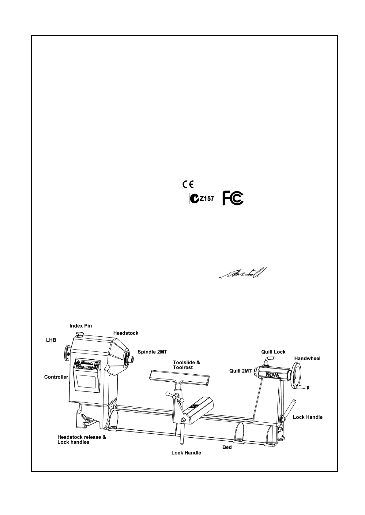
NOVA DVR 2024 Lathe Features at a glance
DVR Electronic drive
The Nova DVR lathes are unique. The DVR incorporates the motor built as part of the headstock, the
spindle and motor are one unit. The motor is almost maintenance free and designed with high
reliability. The Digital Variable Reluctance motor uses smart motor technology to provide an
incredibly smooth and powerful drive. This drive takes turning to a new level. The controller monitors
the spindle position constantly and maintains spindle speed very closely. Additional power is added
as it senses extra load from the tool.
Add on Bed System
A lathe that meets your woodturning needs your workshop space, and your pocket! Each segment is 20" or 510mm in length. This
feature appeals for many different reasons:
As a compact lathe (standard configuration) it is great for small turning workshop spaces.
• As an extended lathe for those wanting to do extra long spindles (beyond the traditional between center of most lathes) the Nova DVR
2024 delivers big turning capacity.
• As a bowl lathe for those just wanting to turn bowls.
Sophisticated Swivel Head
Swivel head lathes have many advantages:
• Space saving
• Allows the turner (not the machine!) to decide the most comfortable position for your turning (saving you from backstrain)
• Elimination of left-hand ‘outboard’ turning techniques and no extra outboard chucks and faceplates are necessary.
There are a number of swivel head lathes available, but Nova DVR have by far the most sophisticated, accurate and easy to use swivel
head on the market.
The Nova DVR lathes can be easily and quickly swiveled to any position (360 degrees). It can be solidly locked in any position plus it has
the added security of a detent pin lock at 0,22.5,45,90 degrees plus 315 (for left-hand use).
The swivel head turns, locks easily and has a very accurate detent position, to lock the spindle in line with the tailstock. The combination of
rigid Tailstock construction and detent pin delivers superb accuracy and is unique to the Nova DVR .
116-0712-006
-2-

Solid Construction
Well proven design, the Nova DVR 2024 is made from Cast Iron components for strength and rigidity. Added features like special webbed
bed design makes the lathe well equipped to take heavy turning stresses. The bed has been designed with vibration dampening qualities a solid 1/2" cross rib is positioned along the bed unit, quickly dissipating any vibration as it travels down the bed. The new powerful
trapezoidal bed design delivers even more vibration damping properties. All this combined with cosmeticall y appeali ng, smoot h fl owing
lines.
Cast iron has always been the material of choice for Woodlathe
construction for its inherent mass and an excellent modulus of
vibration.
Bed Extension Segment Main Bed Segment
New 10 Favourite Speeds Function
Pre-program your most favourite speeds for easy retrieval.
Trapezoidal Bed Design
Powerful with smooth flowing lines, Nova bed design delivers even more vibration dampening propert i es.
New Headstock Design
One piece design increases strength and vibration dampening properties. Micro analysed for optimum design. Same popular swivel
headstock as used in the older DVR and 3000 Lathe models, saves strain on your back.
Adaptive Control Software
Smart adaptive computer technology actually measures the weight of the work piece and adjusts its performance accordingly.
Safety Sensing Feature
Intelligent DVR computer controller senses abnormal turning conditions e.g. a chisel dig in or index left engaged – and instantaneously
shuts down power to the spindle. Normal safety precautions would still apply – see pages 7-8.
Energy Efficient
Unlike other ‘dumb’ electric motors, the Smart DVR Motor only inputs enough power to maintain the set speed – giving you potential for
power savings over conventional motors.
Wide Speed Range
100-5000 rpm, easy push button speed change.
DVR Direct Drive Motor
Driven by unique Direct Drive Variable Reluctance Motor Technology, with superior performance over AC or DC motors. Proven
technology, many thousands of users. No power loss through belts or transmission. Provides digital electronic push button variabl e speed
with no belt changes.
Ultra Smooth Cutting Power
Selected RPM is closely maintained and the DVR has no belt stretch or motor bounce which affects smooth cutting. The DVR motor runs
smooth with almost no vibration.
5 Year Warranty (limited)
On all castings, mechanical parts and components. 2 Year Warranty on all electronics and electrical components.
Plug and Play
Just bolt to stand or bench, plug it in and you are turning! No complex motor set ups or adjustments.
Low Mantainence
The motor is simple, brushless with no rotor windings (rotor is solid steel). The indust rial grade elect roni cs are bui lt to last. There are no
drive pulleys or belts to set up or come loose.
116-0712-006
-3-

Welcome
Thank you for choosing our NOVA DVR 2024 Wood Lathe and welcome to the Teknatool product family. Your
choice shows you want the best for your woodturning and you recognize the superb DVR drive technology and
the host of other unique features the Nova DVR offers.
We strive to achieve the best value for your money – providing quality, innovative features, a wide range of
accessories – plus comprehensive, ongoing support (latest manuals downloadable from our website,
newsletters, projects etc). We are only a phone call or email away with technical advice or assistance on the
operation of your lathe or your woodturnin g queries .
Please feel free to contact us about any aspect of our products or service – we regard our customers as our
best development and improvement team – we would love to hear from you!
Once again, welcome to the “Teknatool NOVA Family”. We trust that you enjoy our products and hope they
enhance the pleasure you experience from the wonderful craft of wood turning!
Best Regards
Brian Latimer
Marketing Director
Teknatool International Ltd
116-0712-006
-4-

Contact Teknatool
Website: http://www.baptist.nl
Email: info@hardwarecentre.co.za
New Zealand
Teknatool International Ltd
Phone: (+64) 9 477 5600
Fax: (+64) 9 477 5601
Email: service@teknatool.com
Website: www.teknatool.com
Carba-Tec NZ Ltd
Free Phone: 0800-444-329
Phone: 274-9454
Website: www.carbatec.co.nz
United States
Teknatool Service Center
Phone: 727-954-3433
Fax: 727-623-0902
Email: service@teknatool.com
Website: www.teknatool.com
Woodcraft Supply Corp
Technical Service: 1-800-535-4486
Orders: 1-800-225-1153
Website: www.woodcraft.com
Australia
Carbatec Australia
Phone: +61 7 3397 2577
Free Fax: +61 7 3390 5280
Email: sales@carbatec.com.au
Website: www.carbatec.com.au
Canada
KMS Tools and Equipment Ltd
Phone: (+1) 604-522-5599
Free Phone: 1-800-567-8979
Fax: (+1) 604-522-0638
Email: kmstools@kmstools.com
Website: www.kmstools.com
Netherlands
United Kingdom
Record Power
Phone: (+44) 0870 770 1777
Fax: (+44) 0870 770 1888
Website: www.recordpower.co.uk
Austria
Neureiter
Phone:+43 6244 202 99
Fax: +43 6244 202 9910
Email: kontakt@neureiter-maschinen.at
France
OTELO
Phone: 0.800 33 11 11
Fax: 01 39 72 16 60
Website: www.otelo.fr
MAISON DU TOURNAGE
Phone: +33-467-232-852
Fax +33-467-230-038
Email: relations.maison.du.tournage@wanadoo.fr
Norway
WWW VERKTOY AS
Phone: 0047-51-88-68-00
Fax: 0047-51-88-68-10
Email: post@verktoyas.no
Website: www.verktoyas.no
Belgium
Willy Vanhoutte BVBA
Phone +32 (50) 78 17 94
Fax + 32 (50) 78 19 64
Email: info@willyvanhoutte.be
Website: http://www.willyvanhoutte.beSouth Africa
The Hardware Centre
Phone: (27) 011 791 0844
Baptist voor Houtbewerkers
Tel: 026 445 16 44
-5-
Fax: (27) 011 791 0850
Website: www.hardwarecentre.co.za
116-0712-006

Table of Contents
GENERAL SAFETY RULES ..................................................................................................................... 7
ADDITIONAL SAFETY RULES FOR WOOD LATHES ............................................................................ 8
DVR 2024 Wood Lathe Specifications ................................................................................................... 9
Workshop Requirements ...................................................................................................................... 10
Assembling the Nova DVR 2024 ........................................................................................................... 11
Nova DVR Components After Unpacking ........................................................................................... 11
Adding an Extension Bed ..................................................................................................................... 12
Mounting the lathe to the Cast Iron Stand ............................................................................................ 13
Mounting the Skirt to the Stand ............................................................................................................ 16
Connecting to Power ............................................................................................................................ 17
Using the NOVA DVR 2024 .................................................................................................................... 18
DVR Drive Functions ............................................................................................................................ 19
Turning Tips .......................................................................................................................................... 21
Swiveling the Headstock ...................................................................................................................... 22
Spindle Index ........................................................................................................................................ 23
Headstock ............................................................................................................................................. 23
Spindle Thread Size ............................................................................................................................... 23
Toolrest ................................................................................................................................................. 25
Tailstock ............................................................................................................................................... 26
Learning Turning .................................................................................................................................. 27
CONTROLLER USER’S GUIDE ................................................................................................................... 28
Programming the Favorite Speeds ....................................................................................................... 33
Maintaining the NOVA DVR 2024 .......................................................................................................... 36
General Maintenance ........................................................................................................................... 36
Cleaning the Toolslide .......................................................................................................................... 37
Cleaning the Tailstock .......................................................................................................................... 37
Aligning the Tailstock ............................................................................................................................ 38
Troubleshooting Guide.......................................................................................................................... 39
Troubleshooting Guide continued ....................................................................................................... 41
NOVA DVR 2024 Wood Lathe Parts List .............................................................................................. 42
Accessories ............................................................................................................................................ 45
Accessories ............................................................................................................................................ 46
Index ........................................................................................................................................................ 48
Teknatool Warranty ................................................................................................................................ 49
© Copyright 2001-2012 by Teknatool International; All Rights Reserved.
Nova DVR is a trademark of Teknatool International Ltd.
The information and specifications contained herein are subject to change. Teknatool is not responsible for errors or
omissions herein or for incidental damages in connection with the furnishing or use of this information.
116-0712-006
-6-

GENERAL SAFETY RULES
Warning! Failure to follow these rules may result in serious personal injury.
1. FOR YOUR OWN SAFETY, READ THE
MANUAL BEFORE OPERATING THE TOOL.
Learn the machine’s application and limitations
plus the specific hazards particular to it.
2. ALWAYS USE A FULL FACE SHIELDStrongly recommended (mus t comply with
ANSI STANDARD Z87.1 -USA) Everyday eyeglasses usually are only impact res istant and
safety glasses only protect eyes. A full face
shield will protect the eyes and face. A lso use
face or dust mask if cutting operation i s dusty.
3. WEAR PROPER APPAREL. Do not wear loose
clothing, gloves , neckties, rings, bracelets or
other jewelry which may get caught in moving
parts. Non slip f ootwear is recommended. Wear
protective hair covering to contai n long hair.
4. USE EAR PROTECTORS. Use ear m uffs for
extended period of operation. Use muffs rated to
103 DBA LEQ (8 hour).
5. DON’T USE IN DANGEROUS ENVIRONMENT.
Don’t use power tools in damp or wet locations,
or expose them to rain. Keep work ar ea well
lighted. The DVR Lat he is intended for indoor
use only. Failure t o do so may void the warr anty.
6. KEEP WORK AREA CLEAN. Cluttered ar eas
and benches invite accidents. Build up of
sawdust is a fire hazard.
7. KEEP CHILDREN AND VISITORS AWAY. The
Nova DVR is not recommended for children
and infirm. Such personnel and onlookers should
be kept a safe distance from work ar ea.
8. MAKE WORKSHOP CHILDPROOF with locks,
master switc hes, or by removing starter keys.
9. GROUND ALL TOOLS. If the t ool is equipped
with a three prong plug, it should be plugged into
a three hole electrical receptacle. If an adapter is
used to accommodate a two prong receptacle,
the adapter plug must be attached to a known
ground. Never remove the third prong.
10. MAKE SURE TOOL IS DISCONNECTED
FROM POWER SUPPLY while the mot or is
being mounted, c onnected, or reconnected.
11. DISCONNECT TOOLS from wall socket before
servicing and when changing acces sories such
as blades, bits, cutters and fuses etc.
12. AVOID ACCIDENTAL STARTING. Make sure
switch is in the Off position before pl ugging in
power cord.
13. NEVER LEAVE MACHINE RUNNING
UNATTENDED. Do not leave machine unless it
is turned off and has come to a complete stop.
14. KEEP GUARDS IN PLACE and in working
order.
15. USE CORRECT TOOLS. Do not use a tool or
attachment to do a job for which it was not
designed.
16. USE RECOMMENDED ACCESSORIES. The
use of improper accessories may cause
hazards.
17. DON’T FORCE THE TOOL. It will do t he job
better and be safer at the rate for which it was
designed.
18. MAINTAIN TOOLS IN TOP CONDITION. Keep
tools sharp and clean for best and safes t
performance. Follow instructi ons for lubricating
and changing acces sories.
19. NEVER STAND ON TOOL. Serious injury could
occur if the tool is tipped or if the cutting tool is
accidentally contacted.
20. REMOVE ADJUSTING KEYS AND
WRENCHES. Form a habit of checking to see
that keys and adjusting wrenches are removed
from tool before turning it on.
21. DON’T OVERREACH. Keep proper footing and
balance at all tim es.
22. DIRECTION OF FEED. Feed wor k into a blade
or cutter against the direction of rotation of the
blade or cutter onl y.
23. ATTENTION TO WORK. Concentrate on your
work. If you become tired or frustr ated, leave it
for awhile and rest.
24. SECURE WORK. Use clamps or a vice to hold
work when practi cal. It’s safer than using your
hand and frees both hands to operate tool .
25. CHECK DAMAGED PARTS. Before fur ther use
of the tool, any part that is damaged should be
carefully checked to ensure that it will operate
properly and perform its intended function.
Check for ali gnm ent of moving parts, binding of
moving parts, m ounting, and any other
conditions that m ay affect its operation. Any
damaged part shoul d be properly repair ed or
replaced.
26. DRUGS, ALCOHOL, MEDICATION. Do not
operate machine whi le under the influence of
drugs, alcohol, or any medication.
27. DUST WARNING. The dust gen erated by
certain woods and wo od products can be
harmful to your healt h. Always operate
machinery in well-ventilated areas and provide
means for proper dus t removal. Use wood dus t
collection systems whenever possible.
116-0712-006
-7-

ADDITIONAL SAFETY RULES FOR WOOD LATHES
important information for you.
Warning! Failure to follow these rules may result in serious personal injury.
Important: ALWAYS BEFORE SWITCHING SPINDLE ON, CHECK SCREEN FOR
CORRECT SETTING
1. DO NOT MODIFY OR USE LATHE FOR USES
OTHER THAN FOR WHICH IT WAS DESIGNED.
2. SEEK INSTRUCTION. If you are not thoroughly
familiar wit h the operation of woodlat hes, obtain
advice from your supervisor, instructor, or other
qualified person. Instruction from a qualified person
is strongly recommended.
3. DO NOT OPERATE LATHE until it is completely
assembled and installed. Follow instructions and
recommendations.
4. FOLLOW ELECTRICAL CODES. M ake sure
wiring codes and recommended electrical
connections are followed and that the machine is
properly grounded.
5. WHEN REPLACING THE FUSE (on relevant
models), completely isolate power when removing
the fuse. It is im perative the plug is removed from
the mains supply before the fuse is r em oved.
Replace fuse cap before reconnecting to mains.
6. DVR ; Do not open the switch and rear covers.
Components can carry dangerous volt ages even
when isolated from m ains power.
7. DVR ; Always ensure spindle fixtures (e.g.
faceplates etc) are locked to spindl e in case
spindle reverse is en gaged. Otherwi se they will
unwind from spindle. See "Mounting a Faceplate to
a chuck" section.
8. WHEN SPINDLE REVERSE IS ENGAGED DO
NOT USE CHISELS OR CUTTING TOOLS - USE
FOR SANDING ONLY
9. KEEP WORK AREA CLEAN. Do not turn the
lathe on before clearing the lathe of all objects
(tools, scraps of wood, etc.). Keep the nearby area
and floor clear of debris.
10. CHECK SET-UP with spindle O ff. Examine the
set-up carefully and rotate the work piece by hand
to check clearance and check speed is correctly
selected before turning on spindle.
11. DO NOT MAKE ADJUSTMENTS when the lat he
or work piece is turning. Make all adjustments with
power Off.
12. TIGHTEN ALL CLAMP HANDLES on the
headstock, tailstock, and toolrest before operating
lathe.
13. EXAMINE WORK PIECE and glue joints before
turning to make sure it has no defects that would
cause it to break when turning.
14. DVR ; ALWAYS CHECK CORRECT SPEED IS
SELECTED BEFORE SWITCHING ON SPINDLE
15. USE LOWEST SPEED when tur ning a new or
unbalanced work piece.
16. TURN AT RECOMMENDED SPEED. Always
operate the lathe at the recommended speeds.
Consult this manual for suggested speeds.
17. ADJUST TOOLREST close to the work piece.
Before turning, r evolve the stock by hand to make
sure it clears t he rest. At intervals, stop the lathe
and readjust the toolrest.
18. KEEP TOOL ON TOOLREST. The lathe t ool or
chisel should be on the toolrest before the lathe is
turned On. Tools should remain on the toolrest
whenever the tool is engaged in contact with the work
piece REMOVE TOOLREST when sanding or
polishing so fi ngers do not get pinched.
19. USE CORRECT LATHE TOOLS. Do not use spindle
turning chisel s for faceplate mou nted work, and vice
versa. Spindle turning tools used f or faceplate
mounted work may grab the work piece and pull the
chisel from your control.
20. WHEN ROUGHING STOCK do not jam the lathe tool
or chisel into wor k piece or take too big a c ut.
21. DO NOT POUND WORK PIECE into headstock drive
(spur) center w hen turning between centers. Pound
the drive center i nto the work piece with a soft mallet
before installing it between center s in the lathe.
22. DO NOT USE TAILSTOCK to drive wor k piece into the
drive (spur) center when turning betw een centers.
Secure work between centers with light pressure fr om
the tailstock quill action.
23. FASTEN STOCK SECURELY BETWEEN CENTERS.
Make sure the tailstock is locked bef ore turning on the
power.
24. NEVER LOOSEN TAILSTOCK SPINDLE or tailstock
while work piece is turning.
25. CORRECT USE OF FACEPLATE. When faceplate
turning, make sure work piece is s ecurely fastened to
the faceplate and t hat appropriate size faceplate is
used to support the work piece. Any screw fasteners
must not interfere with the turning tool at the finished
dimension of the work piece. Rough-cut the work piece
as close as possible to finished shape before installing
on faceplate.
26. DO NOT OPERATE LATHE IF DAMAGED OR
FAULTY. If any part of your lathe is missing, damaged
or broken, in any way, or any electrical component fails,
shut off the lat he and disconnect the l athe from the
power supply. Replace missing, dama ged, or failed
parts before resuming operation.
27. ADDITIONAL SAFETY INFORMATION regar ding the
safe and proper operation of this product is available
from the National Safety Council, 444 N. Michigan
Avenue, Chicago, IL 60611 in the Acc ident Prevention
Manual of Industrial Operations and also in the Safety
Data Sheets provided by the NSC. Also refer to the
American National S tandards Institute ANSI 01.1
Safety Requirement s for Woodworking Machines and
the U.S Department of Labor OSHA 1910.213
Regulation.
Guidelines to symbols used in this manual:
Warning Symbol. Pay close attention!
Note/Information Symbol. Please read -
-8-
116-0712-006
DVR 2024 Wood Lathe Specifications
Size: 1100mm(L) x 240mm (W) x 412mm(H)
43 1/3"(L) x 9 1/2" (W) x 16 1/4"(H)
Weight: 88kg (194 LB) + Legs
Swing Over Bed: 508mm (20in.)
Distance Between Centers: 600mm (24in.);
extendable in 510mm (20in.) units with
add-on Bed sections.
Swing Outboard: 798mm (31in.) with headstock
at 90° using outrigger toolrest.
Headstock:
Spindle Thread: M33 x 3.5 RH
1-1/4 x 8 TPI RH
(2)
(1)
or
Headstock Bore: No. 2 Morse Taper (#2 MT)
Headstock Swivel: 0 to 360 degrees, with
detents at 0, 22.5, 45, and 90 degrees.
Outboard End Internal Thread: M20 x 1.5 LH
Spindle Index: 24 divisions (every 15 degrees)
15mm through-hole through Headstock
Tailstock:
Tailstock Bore: No. 2 Morse Taper (#2 MT)
Quill Travel: 85mm (3-1/4in.)
Hole Through Tailstock: 12mm (7/16in.)
Toolrest:
Length: 300mm (12in.)
Shaft Diameter: 25.4mm (1in.)
Speeds (rpm):
100 – 5000 (in 5rpm increments)
Favourite Speeds:
10 presets
Standard Equipment:
300mm (12in.) Toolrest, 150mm (6in.) Faceplate, Spur
Center, and Live Center. Outboard Handwheel, Cast
Iron Stand, NOVA DVR Wireless Remote.
Optional Accessories:
Precision Midi Chuck
G3 Chuck
SuperNova 2 Chuck
II
Chuck
Titan
80mm (3in.) Faceplate
100mm (4in.) Toolrest
Bowl Toolrest
Outrigger Toolrest Unit
Revolving Center System
Faceplate rings
Swing Away Bed Unit
Notes:
(1) Applicable to Europe (excluding the UK)
(2) Applicable to United States, Canada, United Kingdom,
Australia, New Zealand & South Africa.
For Europe, Australasia, UK and South Africa
Directives this equipment complies with:
Low voltage directive (LVD) 73/23/EEC + 93/68/EEC+2006/95/EC
Machinery directive (MD) 89/392/EEC + 91/368 EEC + 93/68/EEC+2006/42/EC
Electromagnetic compatibility directive (EMCD) 89/336/EEC + 92/31/EEC +
93/68/EEC+2004/108/EC
Harmonized Standards applied in order to verify compliance with Directives:
EN 61029-1:2009 Low Voltage Directive and Machinery Directive
EN 55014-1:2007
EN 55014-2:2009
EN 61000-3-2:Ed3 2006
EN 61000-3-3:1995 A1 + A2
Signed………………………………………..Dated 10/10/11
Nathan Stantiall
Development Manager
116-0712-006
-9-

Setting Up Your Workshop
Workshop Requirements
Consideration Recommendation
Lathe location Locate the Nova DVR 2024 close to a power source in an area with
good lighting. Leave enough clearance on all sides of the lathe;
allow for clearance when the headstock is swiveled. Other
machines in your shop should not interfere with the operation of the
lathe.
Lighting Your shop should have adequate lighting. The work area of the
lathe should be well lit; there should not be shadows cast on your
work. If possible, locate near a window. A portable spotlight may
be helpful.
Electrical The Nova DVR 2024 requires the appropriate power outlet nearby
to power the motor. Wiring and outlets should adhere to local
electrical codes. If in doubt, seek advice from an electrician.
Minimize use of extension cords. See "Connecting to power" section
for Surge Protector requirements.
Ventilation Your shop should be adequately ventilated. The degree of
ventilation will vary based on the size of the shop and the amount of
work done. The use of dust collectors and filters will minimize risks
to your health.
116-0712-006
-10-
Assembling the Nova DVR 2024
handle firmly in thread.
1. Unpack the lathe and components from the shipping container. This is best done by cutting down the
sides of the box to expose the lathe
Warning!
Have other people help when moving or lifting the Nova DVR 2024 Woodlathe; it
weighs 146.2kg (322.3 LB) including stand.
2. Clean any parts coated with rust preventative with a cloth moistened with a petroleum-based solvent or
cleanser, such as paint thinner. Coat the lathe bed with paste wax.
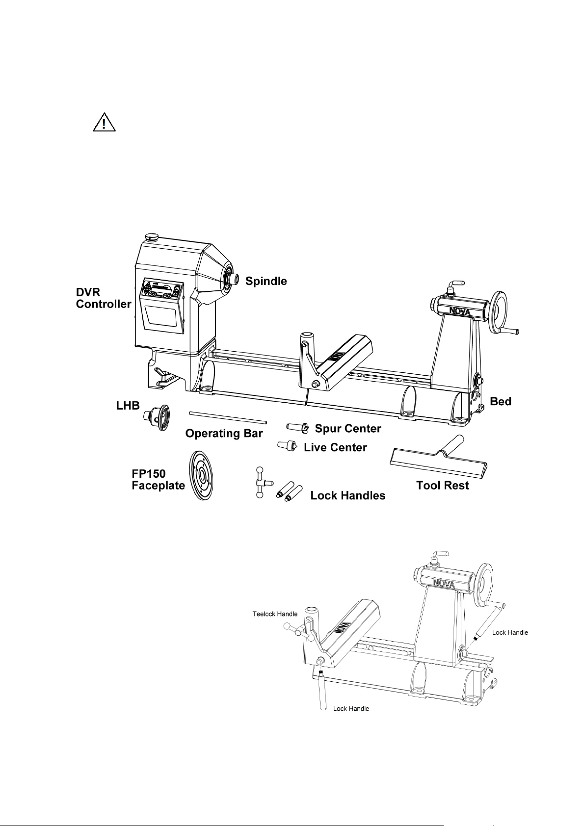
Nova DVR Components After Unpacking
5. Assemble the handles:
Note: Some handles may come pre-
assembled.
Toolrest Clamp Handle -
insert the rod through the handle
and screw the ball knobs onto each
end of the rod.
Toolslide Clamp Handle - screw the
rod lock handle into the Toolslide.
use a hex spanner to lock handle
firmly in thread.
Tailstock Clamp Handle -
screw the lock handle into the
tailstock. Use a hex spanner to lock
-11-
116-0712-006
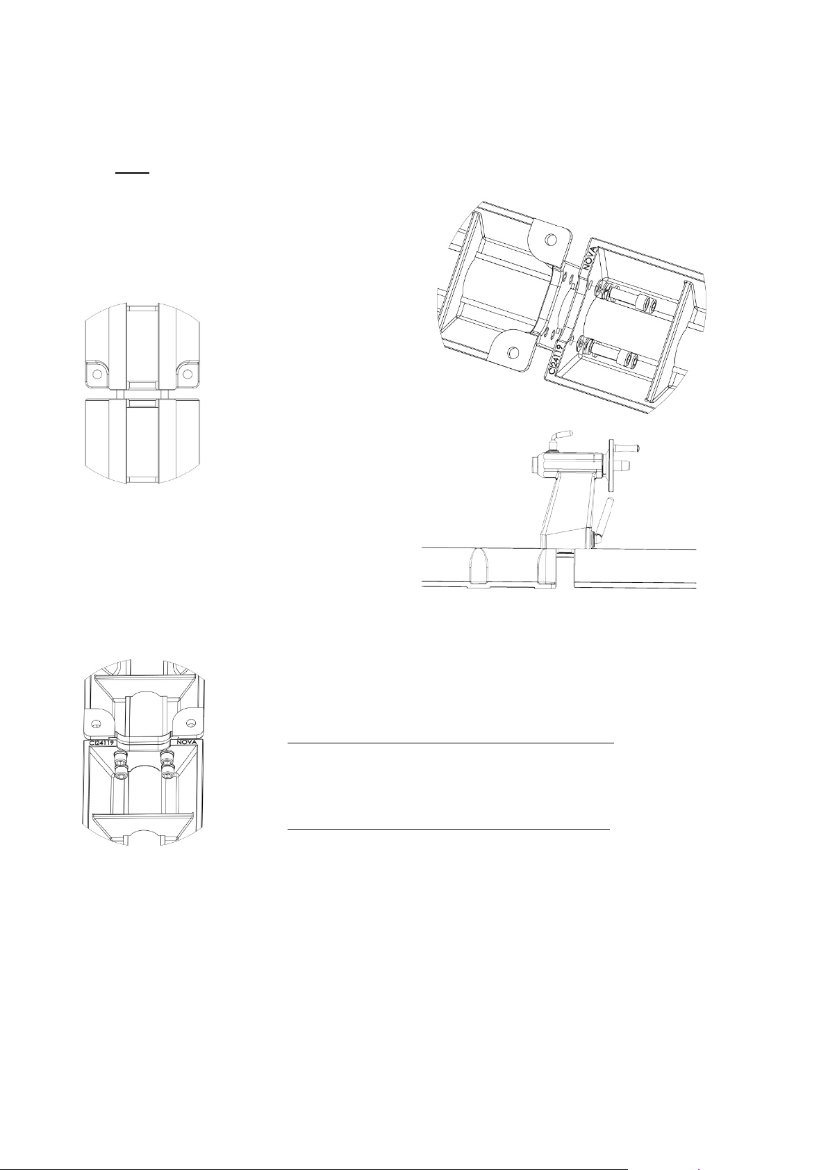
Adding an Extension Bed
Also, wipe off any yellow rust protective, dirt etc (if applicable).
Allen key provided.
30 N-m (22 lb-ft).
and run over the join until the 'railroad clacking' sound disappears.
Each cast iron extension bed adds 510mm (20in.) to the lathe's capacity to turn between centers.
1. Ensure that the bed pieces are flat and the two faces of the bed (which are to be mated) are
clean, free of any burrs and dents.
Note: The end of the extension bed with no feet should be mated to the lathes end face.
2. Place the add on bed extension close to the
lathes end face, align the holes and screw
on the four M12 cap screws (with one spring
washer and flat washer on each)
four tapped holes with the help of the 10mm
Do NOT fully tighten the
cap screws at this stage,
but tighten enough so that
the add on bed extension
is secured
into the
3. Move the tailstock over the two joining extension
beds (tailstock approximately covering equal
length on either extension). Lock the tailstock
firmly over the joining faces
4. Now, use the 10mm Allen key to fully tighten all four cap screws. The torque required is approximately
5. Check that the tailstock runs smoothly over the mating joint, and also over the
full length of the extension. Although all components manufactured by
Teknatool International are made to closest possible tolerances, it is possible
for a difference of approximately 0.1mm to put the bed 'out of true'. The
tailstock can bind in any given area in two possible ways:
A) Jamming between slides (inside the wall of the bed)
Using a smooth flat file, run over the area a few times until the
tailstock frees itself. To maintain central running of the tailstock,
both sides must be filed evenly.
B) The Tailstock clips or appears to jump over the join
The machined flat surfaces may not be quite flush. Use a flat file
-12-
116-0712-006
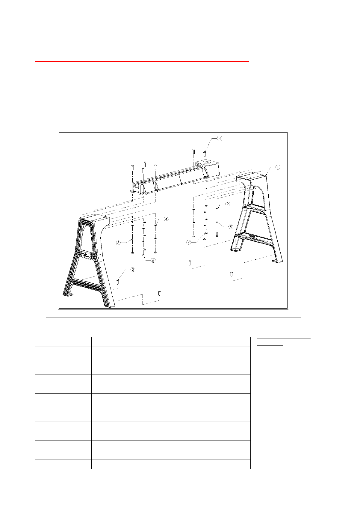
Mounting the lathe to the Cast Iron Stand
NB: Front Face (user side) of casting legs must have skirt fastening holes facing out. See page 16 for skirt fastening instruction.
Parts List
No.
Code
Description
Qty 1 57034
STAND MACHINED CAST IRON NOVA
2
2
BNMZ12030
BOLT ENG M12X30
4 3 BNMZ12050
BOLT ENG M12X50
6 4 FW12
WASHER FLAT M12
6 5 SW12
WASHER SPRING M12
6
6
NHZ12
NUT HEX M12
6
7
BNMZ10035
BOLT ENG M10X35
2 8 SW10
WASHER SPRING M10
2 9 FFW10
WASHER FLAT FENDER M10X32X1.6
2 57058
SKIRT (NOT SHOWN IN PICTURE)
1
NFW06
Nylon Shim (NOT SHOWN IN PICTURE)
8 FFW06
6 Washer C Degree (NOT SHOWN IN PICTURE)
8
MP30608
Screw (NOT SHOWN IN PICTURE)
8
For safety reasons please carefully read and understand these instructions.
The Nova Cast Iron Stand was designed to fit and be used only for Nova Lathes. Use of the stand on
other lathes could void the warranty, and risk personal injury.
The Nova Cast Iron Stand set comprises of two cast iron legs, one on either side, with skirt fastening
holes facing the user. The Stand pieces are cast from a high grade of cast iron with extremely good
section thickness and CAD generated internal gussets at all critical points to withstand extremely high
stresses with practically no distortion. Cast iron has always been the material of choice for wood lathe
construction because of its inherent mass and excellent modulus of vibration dampening.
Suggested Tools for
Assembly
• Ratchet and M10 socket
• At least one other
Person
• Saw benches or
workshop bench both
need to be greater than
860mm
(33 7/8”).
• 5/8” or 16mm Ring/
Open End Spanner
• 3/4” or 19mm
Ring/Open End Spanner
• 8” Adjustable Spanner
116-0712-006
-13-
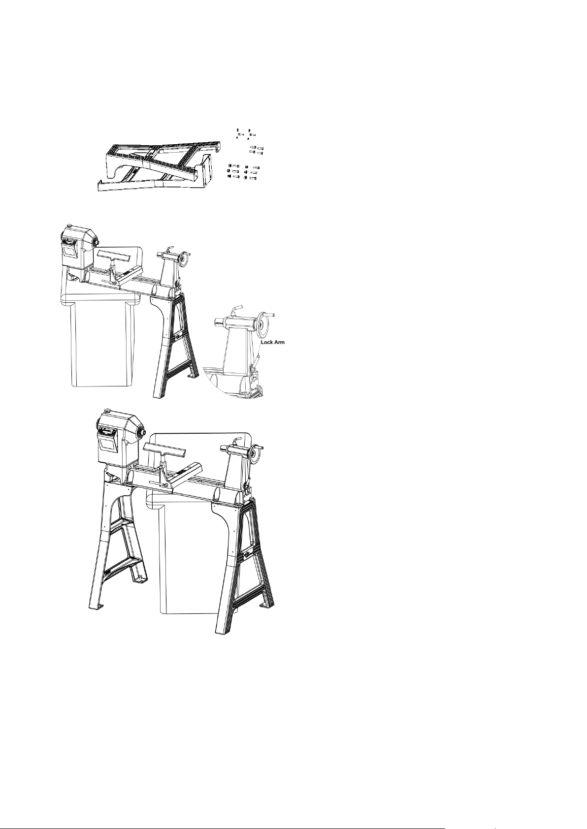
Set up your workshop area before beginning assembly of the lathe stand.
assembly.
the lifting of the lathe.
ASSEMBLY INSTRUCTIONS
SAFETY: The stand and lathe elements are heavy, please ensure correct lifting techniques and equipment are
used and have someone to assist. Use correct tools and observe recommended practices.
1. Open the cardboard box and identify the parts
against the parts lists provided (above)
2. Stand the two legs uprig ht fac ing each other at
approximately the same distance apart as the
length of the lathe. The Stand legs will stand
upright on their two feet, although not very
stable, but this is enough to carry out the
3. For this step you will need a second person
and a table, saw horses or workshop bench of
suitable height. (If the table is not high enough
then you may need to put blocks underneath).
With the help of a second person, move the
lathe from the box and up to the bench or onto
the saw horses. It may be easier to cut the
box away in order to prevent any dangerous
loading on your back.
Notes:
• Check the tailstock is securely fastened by
tightening the lock arm.
Once the following checks have been made the
headstock and the tailstock can be used to assist in
4. Move the lathe on the bench so that the
tailstock end is overhanging and accessible.
Attach the legs sloping to the right on this
end. Drop the M12 x 50 hex bolts through the
holes and then fasten underneath with the
washer and nut.
5. Next do the headstock end. Note that the left
most fastenings are inserted upward into two
blind holes into the lathe bed.
116-0712-006
-14-
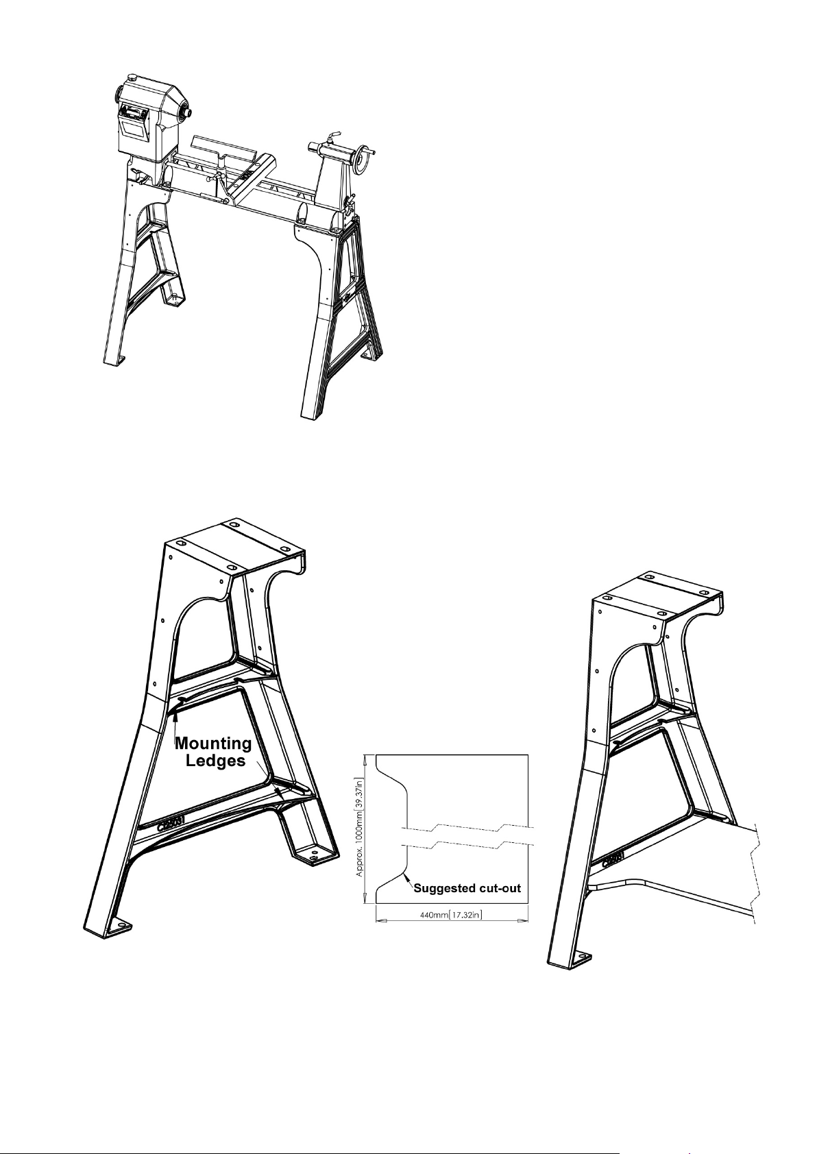
everywhere.
Stand Shelf
6. Now, with the help of a marker, mark the position for
drilling holes into concrete floor for securing the
construction bolts. On the feet of the Stand legs,
there are two holes , one is an M12 tap ped hole for
the jacking bolts, the other is a pla in 14mm hole f or
the construction bolts. T he position for construction
bolts has not been shown in the exploded view.
7. Once the hole posit ions ha ve be en marked, shift the
lathe aside and ins tall the construction bolts. Ref er
to your supplier on the size of drill recom m ended f or
the construction bolts you bu y.
8. Lift and position the complete unit over these
construction bolts. Tighten all nuts firmly.
9. Install all M12x30mm bolts (part 2) for jacking as
shown in the exploded view in the M12 tapped holes
on each of the feet of the Stand legs.
10. Level the lathe bed with the help of the above
jacking bolts with the help of a spirit level.
11. Once the lathe has been le veled tig hte n all
construction bolts firmly.
Re-inspect to ensure all fasteners are firmly secured
The Cast Iron stand has provision for customer shelving between the legs under the lathe. The exac t len gth of
the shelf will depend on how the legs have been setu p and adjusted .
If thicker wood is used, the edges of the shelf ends m ay need to
be relieved to allow the shelf to fit into the leg castings.
For the bottom shelf there
are example dimensions
below.
It is recommended that the
shelf has a cutout along the
front edge to enable free foot
movement around the lathe.
-15-
116-0712-006
 Loading...