

Teknatool 55518RX Users Manual
深 圳 市 盈 峰 电 子 科 技 有 限 公
Shenzhen Y
efo Electronics Technology Co.Lt
User Manual
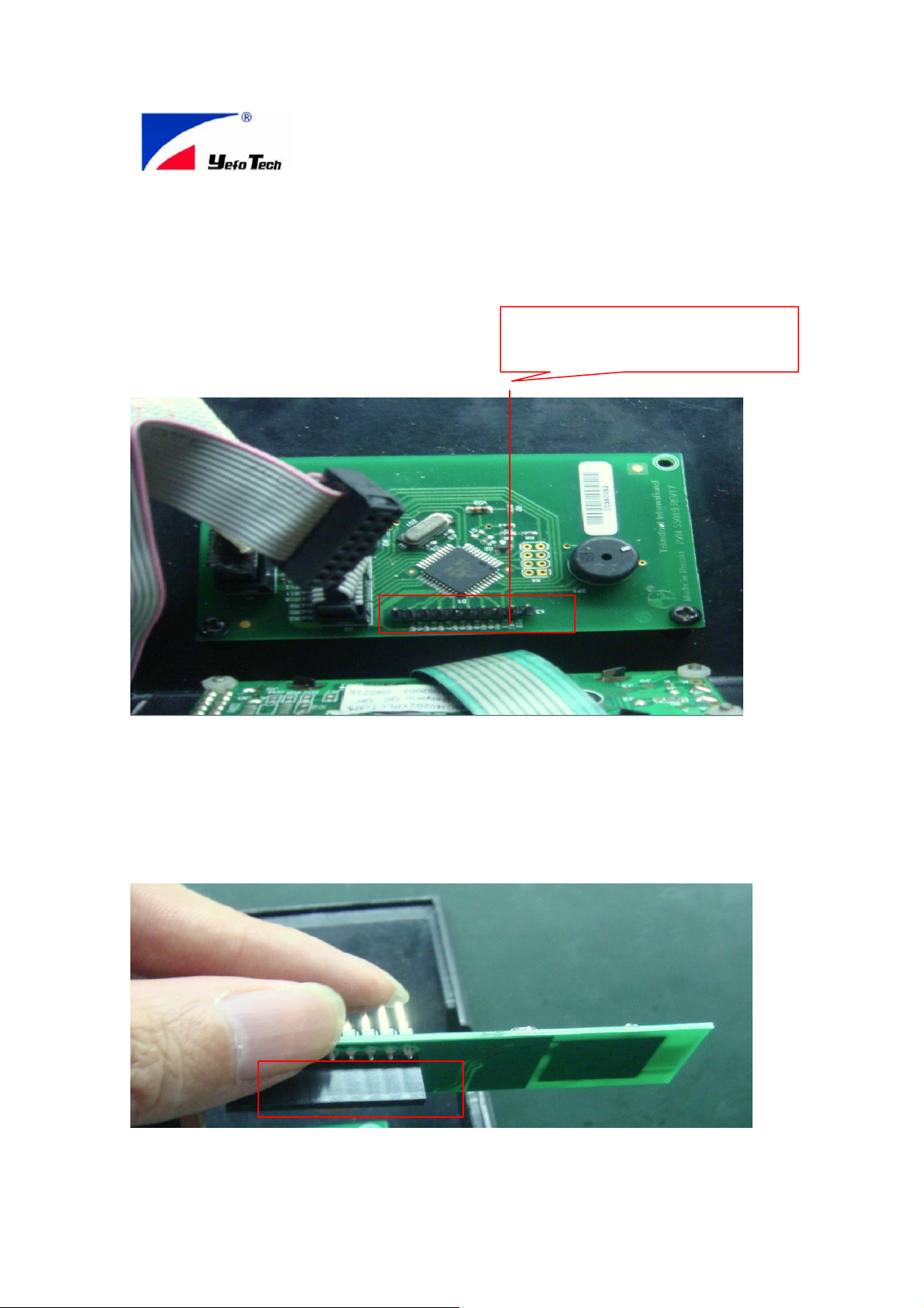
A. Preparing the PCBA socket which providing 3~5VDC power to RX
module as blow red noted
Herein Pin1 and Pin2 along left starting
socket which proving the DC power t to
RX module
B. Inserting the bottom layer connector of RX module into this
socket as below photo, the red line Noted is connector
The status is as left photo
The status is as left photo
after this operation finished
after this operation finished
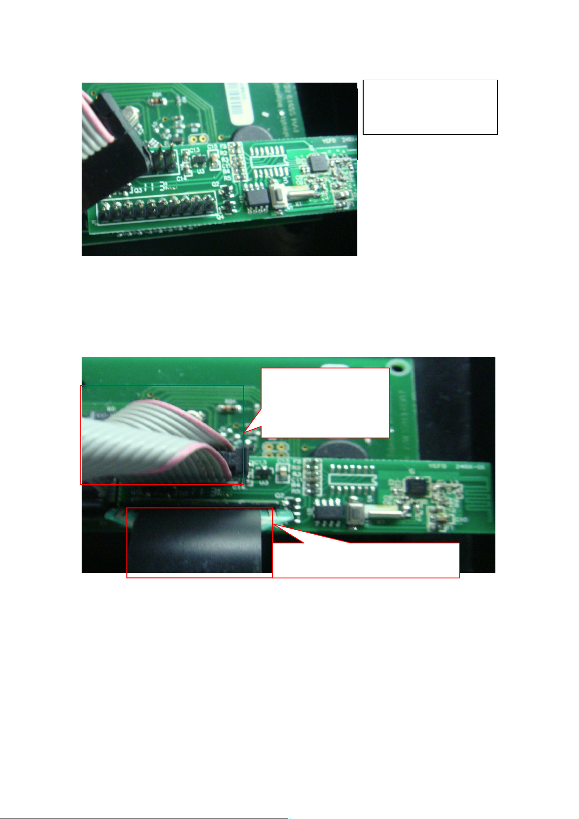
C. Connecting the Top layer two connectors of RX module as
below photo.
This connector transmit
signal to MCU of other
controlling module
This connector transmit signal to LCD
Panel module
Above steps finish hard installation.
D. the program will be loaded to MCU of RX module before SMT
production
Pressing the RX module switch, then pressing power switch of
E.
TX watch, this operation means building handshaking relation
between RX and TX while the LED be lighted from red color to
green color, the verifying method is to up/down the speed switch,
the LCD display will show changed data.
 Loading...