

Teknatool NOVA DVR XP, NOVA DVR 3000, 55016, 55077, 55078 Instruction Manual

115-0214-004 1
NOVA
DVR XP
TM (Xtra Performance)
WOODLATHE
Publication 115-0214-004
INSTRUCTION MANUAL
2 115-0214-004
Models
1)55175 spindle thread 1 1/4" x 8 tpi 115v
2) 55180 spindle thread M33x3.5 220-240v (Europe)
3) 55177 spindle thread 1 1/4" x 8 tpi 220-240v (Australasia)
4) 55178 spindle thread 1 1/4" x 8 tpi 220-240v (UK)
5) 55181 spindle thread 1 1/4" x 8 tpi 220-240v (South Africa)
Nova DVR XP Lathe Features at a glance
DVR Electronic drive
The Nova DVR XP lathe is unique. The DVR incorporates the motor built as part of the headstock,
the spindle and motor are one unit. The motor is almost maintenance free and designed with
high reliability. The Digital Variable Reluctance motor uses smart motor technology to provide
an incredibly smooth and powerful drive. This drive takes turning to a new level. The controller
monitors the spindle position constantly and maintains spindle speed very closely. Additional
power is added as it senses extra load from the tool.
Add on Bed System
A lathe that meets your woodturning needs your workshop space, and your pocket! Each segment is 20" or 510mmin length.
This feature appeals for many different reasons:
As a compact lathe (standard configuration) it is great for small turning workshop spaces.
As an extended lathe for those wanting to do extra long spindles (beyond the traditional between center of most lathes) the
Nova DVR XP delivers big turning capacity.
As a bowl lathe for those just wanting to turn bowls.
Sophisticated Swivel Head
Swivel head lathes have many advantages:
• Space saving
• Allows the turner (not the machine!) to decide the most comfortable position for your turning (saving
you from backstrain)
• Elimination of left-hand ‘outboard’ turning techniques and no extra outboard chucks and faceplates are necessary.
There are a number of swivel head lathes available, but the Nova DVR XP has by far the most sophisticated, accurate and easy
to use swivel head on the market.
The Nova DVR XP lathe can be easily and quickly swiveled to any position (360 degrees). It can be solidly locked in any position
plus it has the added security of a detent pin lock at 0,22.5,45,90 degrees plus 315 (for left-hand use).
The swivel head turns, locks easily and has a very accurate detent position, to lock the spindle in line with the tailstock. The
combination of rigid Tailstock construction and detent pin delivers superb accuracy and is unique to the Nova DVR XP.
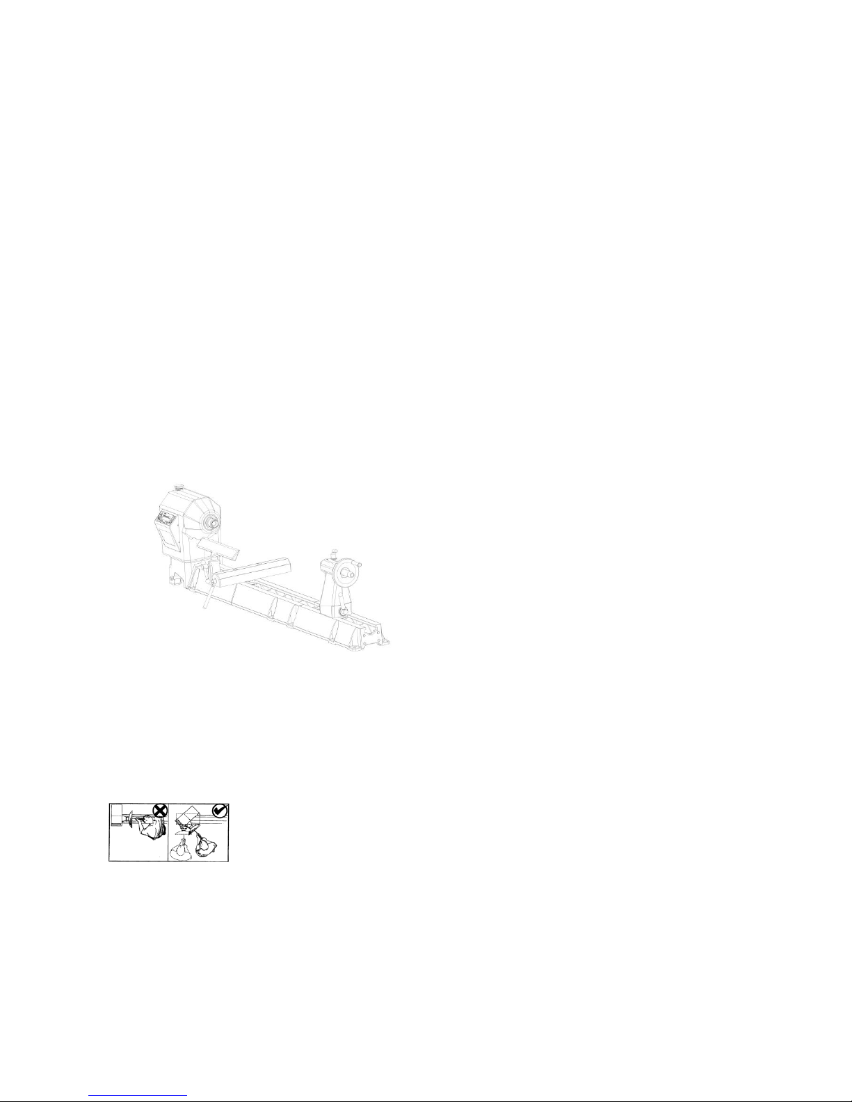
DVR XP extended lathe (Standard model plus one bed segment)

115-0214-004 3
Solid Construction
Well proven design, the Nova DVR XP is made from Cast
Iron components for strength and rigidity. Added features
like the heavy duty TRIMAX triple bearing system and
special webbed bed design makes the lathe well equipped
to take heavy turning stresses. The bed has been
designed with vibration dampening qualities - a solid 1/2"
cross rib is positioned along the bed unit, quickly
dissipating any vibration as it travels down the bed. The
new powerful trapezoidal bed design delivers even more
vibration damping properties. All this combined with
cosmetically appealing, smooth flowing lines.
Cast iron has always been the material of choice for Woodlathe construction for its inherent mass and an excellent modulus of
vibration.
New 5 Favourite Speeds Function
Pre-program your most favourite speeds for easy retrieval.
New Trapezoidal Bed Design
Powerful with smooth flowing lines, new bed design delivers even more vibration dampening properties.
New Headstock Design
One piece design increases strength and vibration dampening properties. Micro analysed for optimum design. Same popular
swivel headstock as used in the older DVR and 3000 Lathe models, saves strain on your back.
Adaptive Control Software
Smart adaptive computer technology actually measures the weight of the workpiece and adjusts its performance accordingly.
Safety Sensing Feature
Intelligent DVR computer controller senses abnormal turning conditions e.g. a chisel dig in or index left engaged – and
instantaneously shuts down power to the spindle. Normal safety precautions would still apply – see pages 7-8.
Energy Efficient
Unlike other ‘dumb’ electric motors, the Smart DVR Motor only inputs enough power to maintain the set speed – giving you
potential for power savings over conventional motors.
Wide Speed Range
100-3500 rpm, easy push button speed change.
DVR Direct Drive Motor
Driven by unique Direct Drive Variable Reluctance Motor Technology, with superior performance over AC or DC motors. Proven
technology, many thousands of users. No power loss through belts or transmission. Provides digital electronic push button
variable speed with no belt changes.
Ultra Smooth Cutting Power
Selected RPM is closely maintained and the DVR has no belt stretch or motor bounce which affects smooth cutting. The DVR
motor runs smooth with almost no vibration.
Trimax Bearing System
Unique Trimax Bearing System is a triple bearing system to provide a smooth, heavy duty load bearing support for the spindle,
which can easily absorb turning stresses.
5 Year Warranty (limited)
On all castings, mechanical parts and components. 2 Year Warranty on all electronics and electrical components.
Plug and Play
Just bolt to stand or bench, plug it in and you are turning! No complex motor set ups or adjustments.
Low Mantainence
The motor is simple, brushless with no rotor windings (rotor is solid steel). The industrial grade electronics are built to last. There
are no drive pulleys or belts to set up or come loose.
Bed Extension Segment Main Bed Segment

4 115-0214-004
Welcome
Thank you for choosing our Nova DVR XP Woodlathe and welcome to the NOVA product family. Your
choice shows you want the best for your woodturning and you recognise the superb DVR drive
technology and the host of other unique features the Nova DVR XP offers.
We strive to achieve the best value for your money – providing quality, innovative features, a wide range
of accessories – plus comprehensive, ongoing support (latest manuals downloadable from our website,
newsletters, projects etc). We are only a phone call or email away with technical advice or assistance on
the operation of your lathe or your woodturning queries.
Please feel free to contact us about any aspect of our products or service – we regard our customers as
our best development and improvement team – we would love to hear from you!
Once again, welcome to the “NOVA Family”. We trust that you enjoy our products and hope they
enhance the pleasure you experience from the wonderful craft of woodturning!
Best Regards
Brian Latimer
Marketing Director
Teknatool International Ltd

115-0214-004 5
Contact NOVA
New Zealand and Rest of the World
Teknatool International Ltd
Phone: (+64) 9 477 5600
Email: service@teknatool.com
Website: www.teknatool.com
United States
NOVA Innovation and Customer Care Center
Phone: 727-954-3433
Email: service@teknatool.com
Website: www.teknatool.com
Or you can contact the retailer where you purchased your NOVA DVR XP Wood lathe, for the contact details please
see our website www.teknatool.com

6 115-0214-004
Table of Contents
GENERAL SAFETY RULES ...................................................................................................................... 7
ADDITIONAL SAFETY RULES FOR WOODLATHES .............................................................................. 8
DVR XP Woodlathe Specifications ............................................................................................................ 9
Workshop Requirements ...................................................................................................................... 10
Lathe Stand Recommendations ........................................................................................................... 10
Example of Shop-made Lathe Stand ....................................................................................................... 11
Assembling the Nova DVR XP ................................................................................................................. 12
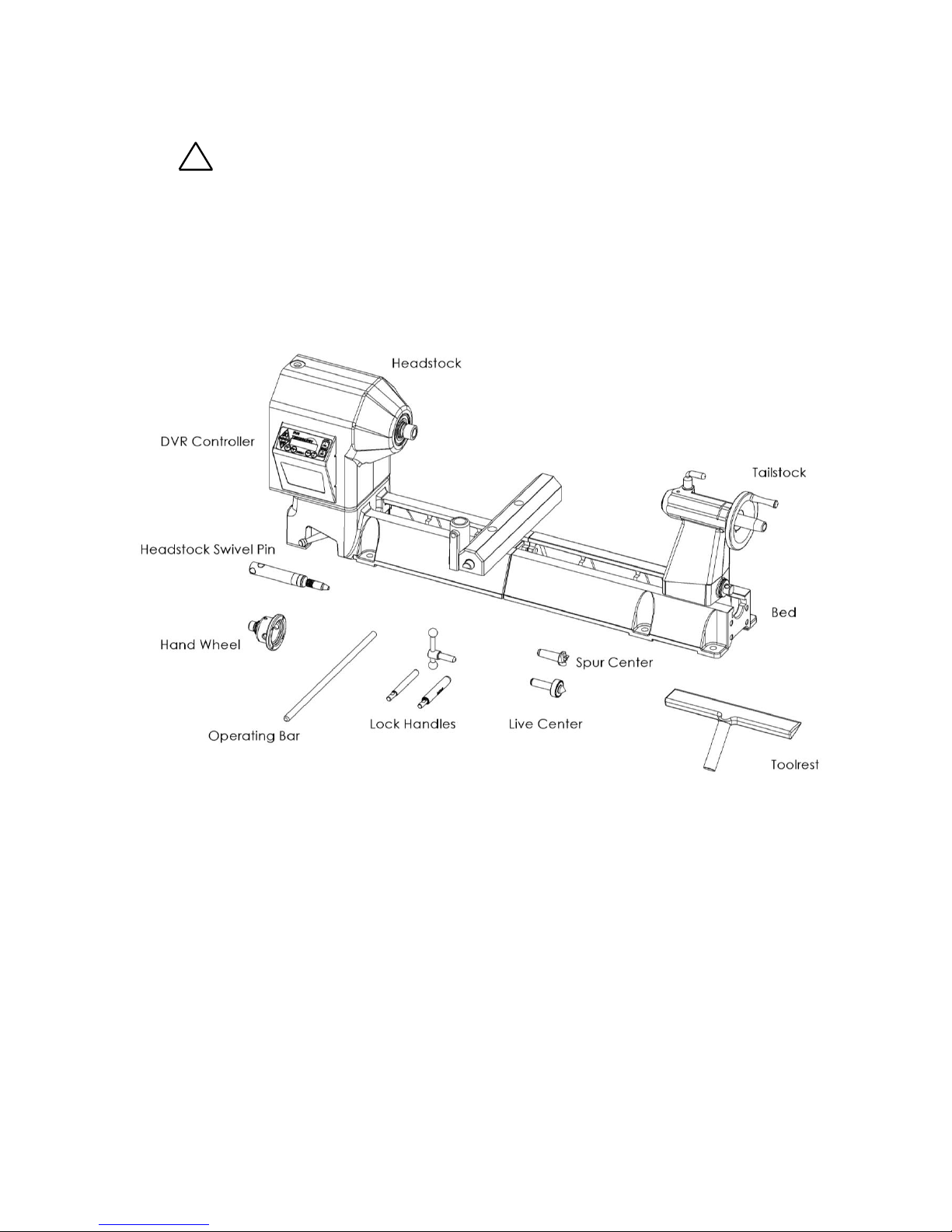
Nova DVR XP Components After Unpacking ...................................................................................... 12
Installing the Headstock Lockpin .............................................................................................................. 13
Adding an Extension Bed ..................................................................................................................... 13
Mounting the Lathe to a Support Surface ............................................................................................. 15
Connecting to Power ............................................................................................................................ 15
Using the Nova DVR XP .......................................................................................................................... 16
DVR Drive Functions ............................................................................................................................ 17
Turning Tips .......................................................................................................................................... 19
Swiveling the Headstock ....................................................................................................................... 20
Spindle Index ........................................................................................................................................ 20
Headstock ............................................................................................................................................. 21
Spindle Thread Size ................................................................................................................................. 21
Toolrest ................................................................................................................................................. 22
Tailstock ............................................................................................................................................... 23
Learning Turning................................................................................................................................... 24
CONTROLLER USER’S GUIDE .............................................................................................................. 25
Programming the Favourate Speeds .................................................................................................... 29
Maintaining the Nova DVR3000 ............................................................................................................... 33
General Maintenance ........................................................................................................................... 33
Cleaning the Toolslide ....................................................................................................................... 34
Cleaning the Tailstock .......................................................................................................................... 34
Aligning the Tailstock ............................................................................................................................ 35
Voltage selection ...................................................................................................................................... 36
Troubleshooting Guide ............................................................................................................................. 38
Troubleshooting Guide continued ............................................................................................................ 40
DVR XP Woodlathe Parts List.................................................................................................................. 41
Accessories .............................................................................................................................................. 44
Accessories .............................................................................................................................................. 45
Index ........................................................................................................................................................ 46
© Copyright 2001-2013 by Teknatool International; All Rights Reserved.
Nova DVR XP is a trademark of Teknatool International Ltd.

115-0214-004
7
The information and specifications contained herein are subject to change. Teknatool is not responsible for errors
or omissions herein or for incidental damages in connection with the furnishing or use of this information.
GENERAL SAFETY RULES
!
Warning! Failure to follow these rules may result in serious personal injury.
1. FOR YOUR OWN SAFETY, READ THE
MANUAL BEFORE OPERATING THE TOOL.
Learn the machine’s application and limitations
plus the specific hazards particular to it.
2. ALWAYS USE A FULL FACE SHIELD-Strongly
recommended (must comply with ANSI
STANDARD Z87.1 -USA) Everyday eye-glasses
usually are only impact resistant and safety
glasses only protect eyes. A full face shield will
protect the eyes and face. Also use face or dust
mask if cutting operation is dusty.
3. WEAR PROPER APPAREL. Do not wear loose
clothing, gloves, neckties, rings, bracelets or
other jewelry which may get caught in moving
parts. Non slip footwear is recommended. Wear
protective hair covering to contain long hair.
4. USE EAR PROTECTORS. Use ear muffs for
extended period of operation. Use muffs rated to
103 DBA LEQ (8 hour).
5. DON’T USE IN DANGEROUS ENVIRONMENT.
Don’t use power tools in damp or wet locations,
or expose them to rain. Keep work area well
lighted. The DVR XP Lathe is intended for indoor
use only. Failure to do so may void the warranty.
6. KEEP WORK AREA CLEAN. Cluttered areas
and benches invite accidents. Build up of
sawdust is a fire hazard.
7. KEEP CHILDREN AND VISITORS AWAY. The
Nova DVR XP is not recommended for children
and infirm. Such personnel and onlookers should
be kept a safe distance from work area.
8. MAKE WORKSHOP CHILDPROOF with locks,
master switches, or by removing starter keys.
9. GROUND ALL TOOLS. If the tool is equipped
with a three prong plug, it should be plugged into
a three hole electrical receptacle. If an adapter is
used to accommodate a two prong receptacle,
the adapter plug must be attached to a known
ground. Never remove the third prong.
10. MAKE SURE TOOL IS DISCONNECTED
FROM POWER SUPPLY while the motor is
being mounted, connected, or reconnected.
11. DISCONNECT TOOLS from wall socket before
servicing and when changing accessories such
as blades, bits, cutters and fuses etc.
12. AVOID ACCIDENTAL STARTING. Make sure
switch is in the Off position before plugging in
power cord.
13. NEVER LEAVE MACHINE RUNNING
UNATTENDED. Do not leave machine unless it
is turned off and has come to a complete stop.
14. KEEP GUARDS IN PLACE and in working
order.
15. USE CORRECT TOOLS. Do not use a tool or
attachment to do a job for which it was not
designed.
16. USE RECOMMENDED ACCESSORIES. The
use of improper accessories may cause
hazards.
17. DON’T FORCE THE TOOL. It will do the job
better and be safer at the rate for which it was
designed.
18. MAINTAIN TOOLS IN TOP CONDITION. Keep
tools sharp and clean for best and safest
performance. Follow instructions for lubricating
and changing accessories.
19. NEVER STAND ON TOOL. Serious injury could
occur if the tool is tipped or if the cutting tool is
accidentally contacted.
20. REMOVE ADJUSTING KEYS AND
WRENCHES. Form a habit of checking to see
that keys and adjusting wrenches are removed
from tool before turning it on.
21. DON’T OVERREACH. Keep proper footing and
balance at all times.
22. DIRECTION OF FEED. Feed work into a blade
or cutter against the direction of rotation of the
blade or cutter only.
23. ATTENTION TO WORK. Concentrate on your
work. If you become tired or frustrated, leave it
for awhile and rest.
24. SECURE WORK. Use clamps or a vice to hold
work when practical. It’s safer than using your
hand and frees both hands to operate tool.
25. CHECK DAMAGED PARTS. Before further use
of the tool, any part that is damaged should be
carefully checked to ensure that it will operate
properly and perform its intended function.
Check for alignment of moving parts, binding of
moving parts, mounting, and any other
conditions that may affect its operation. Any
damaged part should be properly repaired or
replaced.
26. DRUGS, ALCOHOL, MEDICATION. Do not
operate machine while under the influence of
drugs, alcohol, or any medication.
27. DUST WARNING. The dust generated by certain
woods and wood products can be harmful to
your health. Always operate machinery in wellventilated areas and provide means for proper
dust removal. Use wood dust collection systems
whenever possible.

115-0214-004 8
ADDITIONAL SAFETY RULES FOR WOODLATHES
!
Warning! Failure to follow these rules may result in serious personal injury.
Important: ALWAYS BEFORE SWITCHING SPINDLE ON, CHECK SCREEN
FOR CORRECT SETTING
1. DO NOT MODIFY OR USE LATHE FOR USES
OTHER THAN FOR WHICH IT WAS DESIGNED.
2. SEEK INSTRUCTION. If you are not thoroughly
familiar with the operation of woodlathes, obtain
advice from your supervisor, instructor, or other
qualified person. Instruction from a qualified person
is strongly recommended.
3. DO NOT OPERATE LATHE until it is completely
assembled and installed. Follow instructions and
recommendations.
4. FOLLOW ELECTRICAL CODES. Make sure
wiring codes and recommended electrical
connections are followed and that the machine is
properly grounded.
5. WHEN REPLACING THE FUSE (on relevant
models), completely isolate power when removing
the fuse. It is imperative the plug is removed from
the mains supply before the fuse is removed.
Replace fuse cap before reconnecting to mains.
6. DVR XP; Do not open the switch and rear
covers. Components can carry dangerous
voltages even when isolated from mains power.
7. DVR XP; Always ensure spindle fixtures (e.g.
faceplates etc) are locked to spindle in case
spindle reverse is engaged. Otherwise they will
unwind from spindle. See "Mounting a Faceplate to
a chuck" section.
8. WHEN SPINDLE REVERSE IS ENGAGED DO
NOT USE CHISELS OR CUTTING TOOLS - USE
FOR SANDING ONLY
9. KEEP WORK AREA CLEAN. Do not turn the lathe
on before clearing the lathe of all objects (tools,
scraps of wood, etc.). Keep the nearby area and
floor clear of debris.
10. CHECK SET-UP with spindle Off. Examine the
set-up carefully and rotate the work piece by hand
to check clearance and check speed is correctly
selected before turning on spindle.
11. DO NOT MAKE ADJUSTMENTS when the lathe or
work piece is turning. Make all adjustments with
power Off.
12. TIGHTEN ALL CLAMP HANDLES on the
headstock, tailstock, and toolrest before operating
lathe.
13. EXAMINE WORK PIECE and glue joints before
turning to make sure it has no defects that would
cause it to break when turning.
14. DVR XP; ALWAYS CHECK CORRECT SPEED IS
SELECTED BEFORE SWITCHING ON SPINDLE
15. USE LOWEST SPEED when turning a new or
unbalanced work piece.
16. TURN AT RECOMMENDED SPEED. Always
operate the lathe at the recommended speeds.
Consult this manual for suggested speeds.
17. ADJUST TOOLREST close to the work piece.
Before turning, revolve the stock by hand to make
sure it clears the rest. At intervals, stop the lathe
and readjust the toolrest.
18. KEEP TOOL ON TOOLREST. The lathe tool or
chisel should be on the toolrest before the lathe is
turned On. Tools should remain on the toolrest
whenever the tool is engaged in contact with the work
piece REMOVE TOOLREST when sanding or
polishing so fingers do not get pinched.
19. USE CORRECT LATHE TOOLS. Do not use spindle
turning chisels for faceplate mounted work, and vice
versa. Spindle turning tools used for faceplate
mounted work may grab the work piece and pull the
chisel from your control.
20. WHEN ROUGHING STOCK do not jam the lathe tool
or chisel into work piece or take too big a cut.
21. DO NOT POUND WORK PIECE into headstock drive
(spur) center when turning between centers. Pound the
drive center into the work piece with a soft mallet
before installing it between centers in the lathe.
22. DO NOT USE TAILSTOCK to drive work piece into the
drive (spur) center when turning between centers.
Secure work between centers with light pressure from
the tailstock quill action.
23. FASTEN STOCK SECURELY BETWEEN CENTERS.
Make sure the tailstock is locked before turning on the
power.
24. NEVER LOOSEN TAILSTOCK SPINDLE or tailstock
while work piece is turning.
25. CORRECT USE OF FACEPLATE. When faceplate
turning, make sure work piece is securely fastened to
the faceplate and that appropriate size faceplate is
used to support the work piece. Any screw fasteners
must not interfere with the turning tool at the finished
dimension of the work piece. Rough-cut the work piece
as close as possible to finished shape before installing
on faceplate.
26. DO NOT OPERATE LATHE IF DAMAGED OR
FAULTY. If any part of your lathe is missing, damaged
or broken, in any way, or any electrical component fails,
shut off the lathe and disconnect the lathe from the
power supply. Replace missing, damaged, or failed
parts before resuming operation.
27. ADDITIONAL SAFETY INFORMATION regarding the
safe and proper operation of this product is available
from the National Safety Council, 444 N. Michigan
Avenue, Chicago, IL 60611 in the Accident Prevention
Manual of Industrial Operations and also in the Safety
Data Sheets provided by the NSC. Also refer to the
American National Standards Institute ANSI 01.1
Safety Requirements for Woodworking Machines and
the U.S Department of Labor OSHA 1910.213
Regulation.
Guidelines to symbols used in this manual:
!
Warning Symbol. Pay close attention!
Note/Information Symbol. Please read -
important information for you.

115-0214-004
9
DVR XP Woodlathe Specifications
Size: 1100mm(L) x 240mm (W) x 412mm(H)
43 1/3"(L) x 9 1/2" (W) x 16 1/4"(H)
Weight: 82kg (181 LB)
Swing Over Bed: 400mm (16in.)
Distance Between Centers: 600mm (24in.);
extendable in 510mm (20in.) units with
add-on Bed sections.
Swing Outboard: 740mm (29in.) with headstock
at 90° using outrigger toolrest.
Headstock:
Spindle Thread: M33 x 3.5 RH
(1)
or
1-1/4 x 8 TPI RH
(2)
Headstock Bore: No. 2 Morse Taper (#2 MT)
Headstock Swivel: 0 to 360 degrees, with
detents at 0, 22.5, 45, and 90 degrees.
Outboard End Internal Thread: M20 x 1.5 LH
Spindle Index: 24 divisions (every 15 degrees) 15mm
through-hole through Headstock
Tailstock:
Tailstock Bore: No. 2 Morse Taper (#2 MT)
Quill Travel: 85mm (3-1/4in.)
Hole Through Tailstock: 15mm (9/16in.)
Toolrest:
Length: 300mm (12in.)
Shaft Diameter: 25.4mm (1in.)
Speeds (rpm):
100 – 3500 (in 5rpm increments)
Favourite Speeds:
5 presets
Standard Equipment:
300mm (12in.) Toolrest, 80mm (3in.) Faceplate* (Not
all countries, see notes below), (Not all countries, see
notes below) Spur Center, and Live Center. Outboard
Handwheel.
Nova 3000 Bowl Lathe Version:
Specifically for bowl turning, does not include bed
extension, tailstock, and centers.
Optional Accessories:
Precision Midi, G3, SuperNova 2 & Titan Chuck
80mm (3in.) Faceplate
Vacuum Faceplate
100mm (4in.) Toolrest
Bowl Toolrest
Outrigger Toolrest Unit
Vacuum Coupler
Revolving Center System
Faceplate rings
Notes:
(1) Applicable to Europe (excluding the UK)
(2) Applicable to United States, Canada, United Kingdom,
Australia, New Zealand & South Africa.
* Note: Standard equipment varies from country to country, In
some markets, the faceplate is an optional accessory. Check with
your reseller if you are unsure.
For Europe, Australasia, UK and South Africa
Directives this equipment complies with:
Low voltage directive (LVD) 73/23/EEC + 93/68/EEC +2006/95/EC
Machinery directive (MD) 89/392/EEC + 91/368 EEC + 93/68/EEC +
2006/42/EC Electromagnetic compatibility directive (EMCD)
89/336/EEC + 92/31/EEC + 93/68/EEC + 2004/108/EC
Harmonized Standards applied in order to verify compliance with
Directives:
EN 61029-1:2009 (Low Voltage Directive and Machinery
Directive)
EN 55014-1:2007
EN 55014-2:2009
EN 61000-3-2: Ed3 2006
EN 61000-3-3:1995 A1 + A2
Signed………………………………………..Dated 10/12/2010
Nathan Stantiall
Development Manager

115-0214-004 10
Setting Up Your Workshop
Workshop Requirements
Consideration
Recommendation
Lathe location
Locate the Nova DVR XP close to a power source in an area with
good lighting. Leave enough clearance on all sides of the lathe;
allow for motor clearance when the headstock is swiveled. Other
machines in your shop should not interfere with the operation of the
lathe.
Lighting
Your shop should have adequate lighting. The work area of the
lathe should be well lit; there should not be shadows cast on your
work. If possible, locate near a window. A portable spotlight may be
helpful.
Electrical
The Nova DVR XP requires the appropriate power outlet nearby to
power the motor. Wiring and outlets should adhere to local electrical
codes. If in doubt, seek advice from an electrician. Minimize use of
extension cords. See "Connecting to power" section for Surge
Protector requirements.
Ventilation
Your shop should be adequately ventilated. The degree of
ventilation will vary based on the size of the shop and the amount of
work done. The use of dust collectors and filters will minimize risks
to your health.
Lathe Stand Recommendations
A sturdy and rigid stand is required so that the Nova DVR XP Woodlathe can deliver optimum
performance. A common flaw with many woodlathe installations is an inadequate stand for the lathe.
The larger the size of your turnings, the greater the importance of the lathe stand design.
Consideration
Recommendation
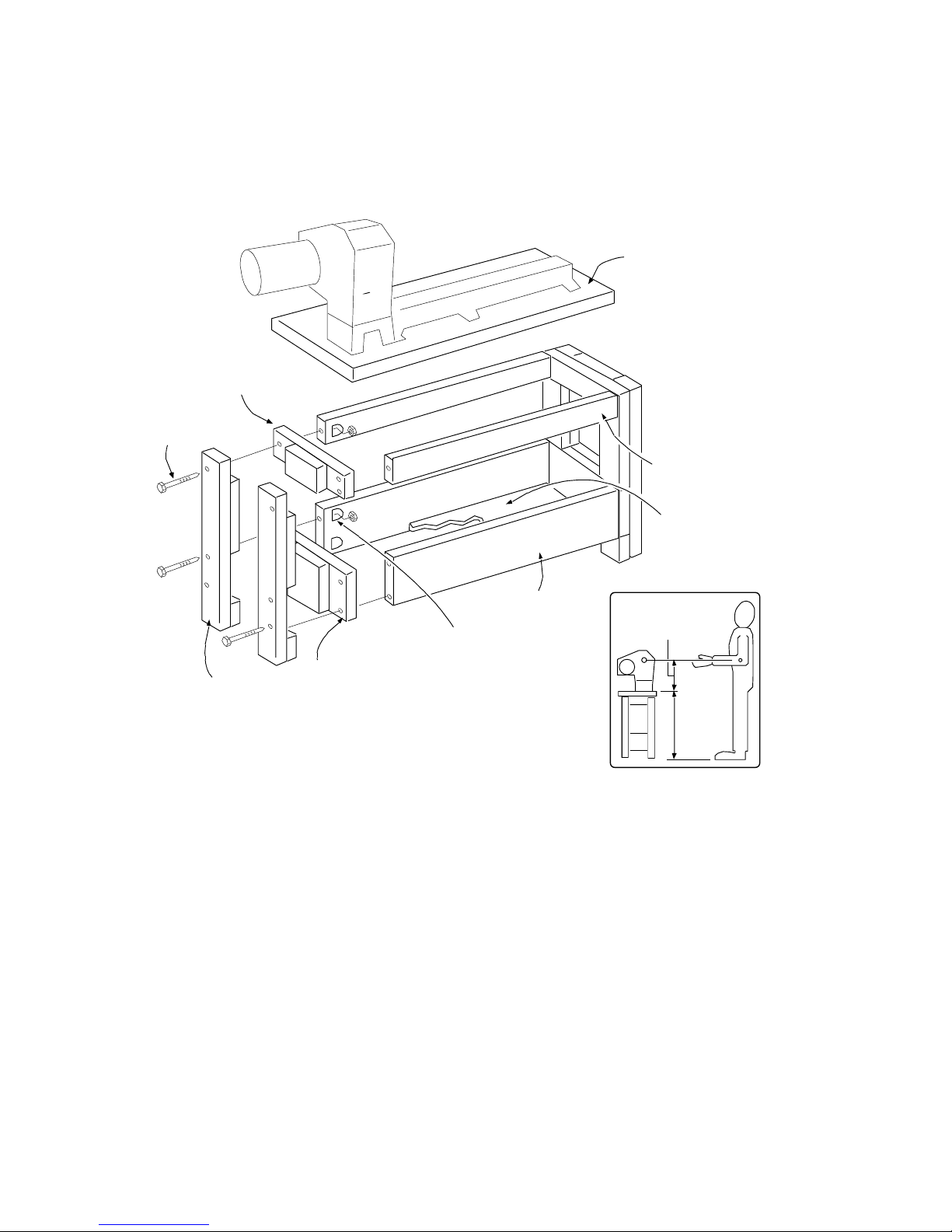
Lathe Height
from floor
The height of the stand should locate the centerline of the lathe
spindle at the elbow height of the turner.( illustration next page)
Stand Top
The stand top should be flat so the lathe does not twist when it
is bolted down. Check for any gaps between lathe feet and
stand top before bolting down. Shim and prepare stand as
necessary.
Stand Weight
The stand should have enough weight and mass so that it
doesn't move when turning large work pieces, and so that the
stand can absorb vibrations. A lathe stand's stability can be
improved by weighing it down with sand bags on a lower shelf.
Stand Legs
The stand should sit level on the floor and not rock.
115-0214-004
11
Example of Shop-made Lathe Stand
This has been designed with economy of space in mind. Heavier sections, wider rails and gussets on
the corners are encouraged. For stability and vibration dampening, it is highly recommended that the
base is filled with sand.
297 mm
(11-11/16 in.)
to suit
turner
Top
43 x 16 x 2 in.
plywood bottom
(compartment for sand)
Lower Rail (2)
1-1/2 x 7-1/2 x 33 in.
Leg (4)
1-1/2 x 3-1/2 in. x
height to suit turner
Upper Leg Brace (2)
1-1/2 x 3-1/2 x 13 in.
Lower Leg Brace (2)
1-1/2 x 7-1/2 x 13 in.
Upper Rail (2)
1-1/2 x 3-1/2 x 33 in.
Glue and screw leg pieces
Recessed Hole,
drill hole and chisel one
side square for nut.
Machine
Bolt (12)
115-0214-004 12
Assembling the Nova DVR XP
1. Unpack the lathe and components from the shipping container. This is best done by cutting down
the sides of the box to expose the lathe
!
Warning!
Have other people help when moving or lifting the Nova DVR XP Woodlathe; it
weighs about 82kg (181 LB).
2. Clean any parts coated with rust preventative with a cloth moistened with a petroleum-based
solvent or cleanser, such as paint thinner. Coat the lathe bed with paste wax.
Nova DVR XP Components After Unpacking
115-0214-004
13
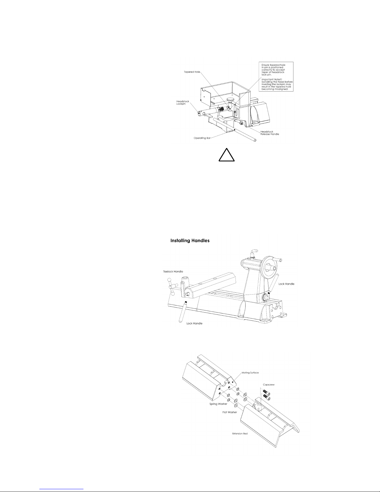
Installing the Headstock Lockpin
3. Remove the plastic shipping tube
from headstock base. Immediately
screw the Headstock Lockpin into
the threaded hole at the bottom of
the headstock. Insert the operating
bar into the hole in the Lockpin and
firmly tighten the Lockpin to lock the
headstock in position; then remove
the operating bar. NOTE: When the
pin is fully engaged the groove
machined into the pin furthest from
the thread should line up with the
edge of the hole in the casting. By
doing this the pin will be engaged in
the hole of the swivel pin.
4. Loosen the Lockpin 1 – 2 turns.
Push the Headstock Release
Handle down and rotate the
Headstock so the spindle points to
the tailstock and lines up parallel to
the lathe bed. Tighten lock pin
again.
Note: Do not use excessive force when
tightening the Lockpin.
!
Important note: Swiveling the head before inserting
the lock pin may result in the tapped hole on the
Swivel pin becoming mis-aligned.
5. Assemble the handles:
Note: Some handles may come pre-
assembled.
Toolrest Clamp Handle -
insert the rod through the handle
and screw the ball knobs onto
each end of the rod.
Toolslide Clamp Handle - screw
the lock handle into the toolslide.
Tailstock Clamp Handle -
screw the lock handle into the
tailstock.
Adding an Extension Bed
Each cast iron extension bed adds 510mm
(20in.) to the lathe's capacity to turn between
centers.
1. Clean the joining ends of both bed sections
with a petroleum-based solvent. Make sure
there are no dents or burrs on either mating
surface. Remove burrs and high spots with
a smooth file.
2. Screw in cap screws tight
3. Secure the bed sections together with four
M12x30 cap screws using a 10mm Allen
wrench. It may be necessary to move the
lathe so the cap screws can be reached

115-0214-004 14
with the wrench from the bottom of the bed.
!
Warning!
Do not use a metal hammer to pound on the extension bed. This may damage the bed, affect
accuracy and tailstock action, and may prevent you from adding another extension bed.
4. Bring the Tailstock along until it is on top of the join area where the bed extension face meets the
lathe bed face. The bed extension may need to be manipulated up-and-down and sideways in
order for the Tailstock to fit.
5. Check that the toolslide and tailstock move freely over the mating joint and also over the full length
of the add-on extension. If there is a ridge between the two mating surfaces then repeat steps 1 - 4
again, use a smooth file to file the surfaces flush.
6. Follow the suggestions under "Mounting the Lathe to a Support Surface".
115-0214-004
15
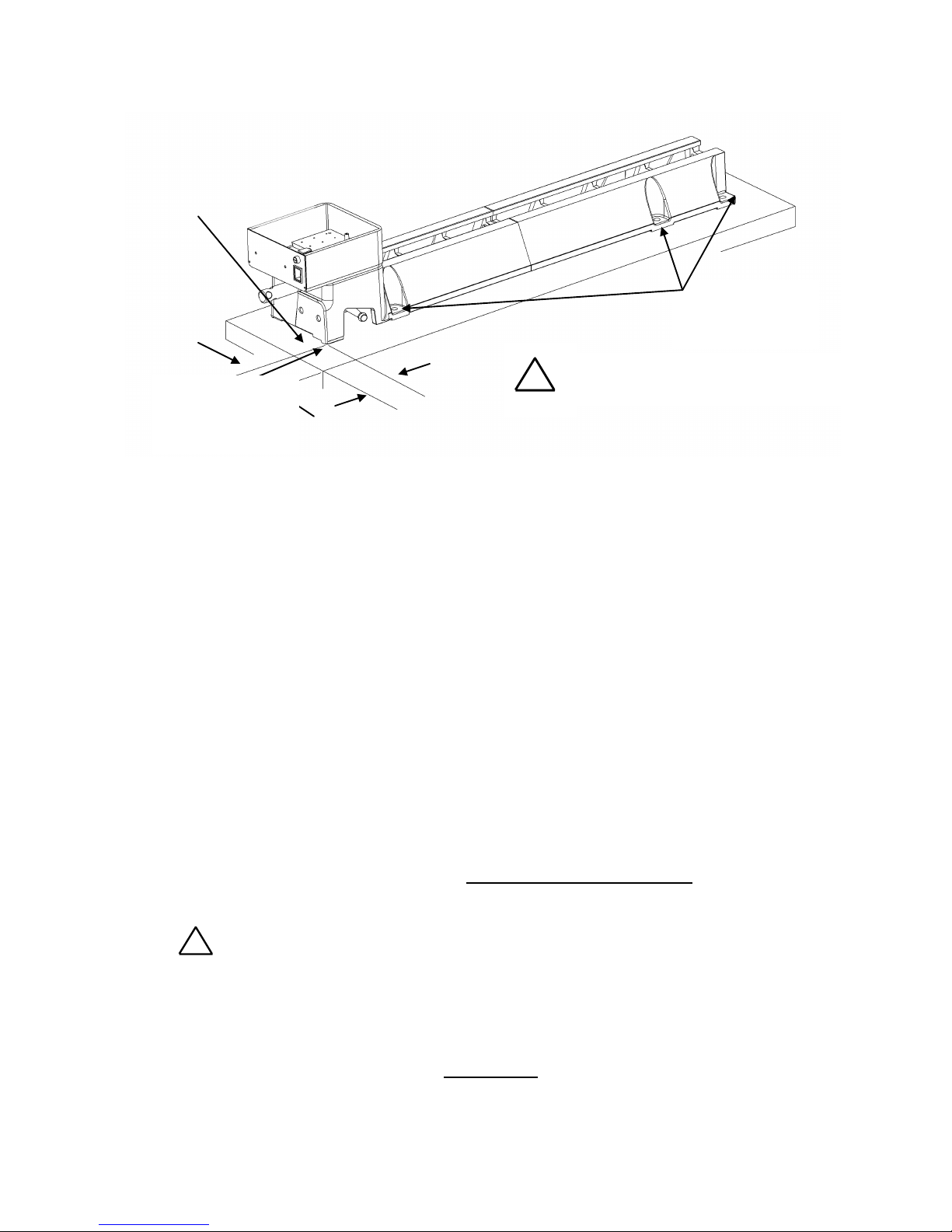
Mounting the Lathe to a Support Surface
1. Place the lathe on the stand top. Locate the front and left corner of the lathe approximately 25mm
(1in.) from the corner edge of the stand top. This provides a comfortable reach when turning and
allows the optional outrigger unit to be easily installed.
2. If necessary, mark the six hole locations on the top and drill M12 holes.
3. Place a spirit level along the top of the lathe bed. Any movement of the bubble as the lathe is
secured, indicates a twist on the bed. For the lathe to operate correctly the bed must not twist; if
necessary, use shims between the bed and stand top.
4. Use bolts of suitable length (not included) to secure the lathe. Tighten the two headstock bolts first,
then the two tailstock bolts, and finally tighten the last two bolts on top.
5. The two M10 threaded holes underneath the outrigger end of headstock can be optionally used
(making a total of 8 bolt positions). Ensure that the bolt is a metric M10 x 1.5mm pitch and that the
length is correct to ensure that the bolt doesn't bottom in the threaded hole and potentially damage
casting.
Connecting to Power
The power cord should be 3-wire, having a grounding conductor and a grounding plug. The plug must
be plugged into a matching outlet that is properly installed and grounded in accordance with local
electrical codes.
The DVR XP can run on either 115v or 220v ~ 240v, but the voltage must be selected with an internal
jumper (see Voltage Selection page 36). If the lathe is purchased in USA, it will already be setup for
115v operation. All other countries are preset for 220v ~ 240v.
!
Warning!
Improper connection of the motor can result in a risk of electrical shock.
If it is necessary to use an extension cord, the cord should be grounded. Use the correct wire size for
the extension cord, for a given cord length, to avoid power loss and over-heating.
IMPORTANT: A Surge Protection Device rated to at least 15 amps - for USA and
Canada, other countries 10 or 15 amps - must be used to protect the DVR electronics from
electrical spikes or surges, similar to those used on most Home PC's.
Ground Fault Interrupters (GFI's) or Residual Current Detectors (RCD's) are helpful and are a
recommended protection device for any powertool. They can be used in conjunction with a DVR
lathe. Note some makes of GFI may not be compatible
The lathe must be fastened to a support
surface, such as a lathe stand or bench
Mounting Holes(6)
(M12 x 1.75 Bolts)
Maximum of 25mm (1in.)
(Required only for mounting
the Outrigger Unit option
!
Optional Mounting
Underneath lathe
2 x (M10 x 1.5)
 Loading...