

Tekcom TM 366 Users Manual
VHF255S DSC MARINE RADIO
TM366-USA
25/1 Watt VHF/FM
OPERATOR WARNING
HUMMIINBIRD requires the radio operator to meet the requirements for
Radio Frequency Exposure. Unauthorized changes or modifications to
this equipment may void compliance with ***Rule.Any change or
modification must be approved in writing by HUMMIINBIRD Corp
This equipment has been tested and licensed to comply with the limits for Class
D Digital Marine Devices. These limits are designed to provide reasonable
protection against harmful interference in a residential installation. This
equipment can generate or radiate radio frequency energy and, if not installed
and used in accordance with the instructions, may cause harmful interference to
radio communications and human body. Never transmit before you make sure
the antenna is properly located.
This device is only an aid to navigation. Its performance can be affected by many
factors including equipment failure or defects, environmental condition and
improper handling or use. It is the user's responsibility to exercise common
prudence and navigational judgement, and this device should not be relied upon
as a substitute for such prudence and judgement. Your Radio Ocean VHF radio
generates and radiates radio frequency (RF) electromagnetic energy (EME). This
equipment must be installed and operated in accordance with the instructions
contained in this handbook. Failure to do so can result in personal injury and/or
product malfunction.

TABLE OF CONTENTS
EQUIPMETN DESCRIPTION…………………………………….……………………3
1.1 INTRODUCTION…………………………………………………………….3
2. CONTROLS AND LCD DISPLAY…………………………………………4
2.1 BASE STATION PANEL……….……………….…………………….……5
2. 2 BASE STATION PANEL (REAR)…………..……………………..………6
2. 3 HANDSET………………….……………………………………………...…7
2. 4 LIQUID CRYSTAL DISPLAY……..………………………………..….……8
3.I INSTALLATION…………………….……………………………….….…….8
SUPPLIED ACCESSORIES………………………………………….……8
3.2 LOCATION…………………………………………………………….……8
3.3 CONNECTIONS………………….………….……………………..………8
3.4 MOUNTING THE RADIO………..……..………………………………….9
3.5 ANTENNA MOUNTING/THE EMC EXPOSURE…………………..……11
3.6 MOUNTING THE HANDSET……………………………………………..12
4 BASE OPERATION………………………….………………………….…13
4.1 TRANSMISSION AND RECEPTION…….………………..…………….14
4.2 BAND SWITCH……………………….…………………………………….14
4.3 SAVE FAV CHANNELS………….………………………….………….…15
4.4 TRANSMIT TIME-OUT-TIME……………………………………………..16
4.5 SCAN………………………………………………………..………………16
4.6 WATCH ………………………………………………………..……………17
4.7.1 Dual WATCH………………………………………………….……………17
4.7.2 TRI WATCH ……………………………………………………..…………17
4.8 POSITION INDICATION……………………………..……………………17
5.0 DIGITAL SELECTIVE CALLING………………..………………….……17
5.1 GENERAL………………………………………………….….……..17
5.1.1 MARITIME MOBILE SERVICE IDENTITY(MMIS)L….…………………17
5.1.2 HOW CAN I OBTAIN MMSI ASSIGNMENT?………………………..18
5.2. DSC CALL TYPE ………………………………………………………….18
5.2.1 SEND A DISTRESS CALL……………………………...……………..…19
5.2.2 SEND AN ALL SHIPS CALL…….………………………………….……20
5.2.3 SEND A GROUP CALL……………….………………………………..…21
5.2.4 MAKE A ROUTING CALL (INDIVIDUAL)………………………….…...21
5.2.4.1 MANUALLY SENDING AN INDIVIDUAL CALL……………...………..21
5.2.4.2 SENDING AN INDIVIDUAL CALL)………………………………….…..22
5.2.4.3 ACK OF AN INDIVIDUAL INCOMING………………………....……….23
5.2.5 LAST CALL………………………………………………………………...23
5.2.6 SENDING AN INDIVIDUAL CALL USING THE CALL LOG……...….23
5.2.7.1 POS REQUEST…………………………………………………………….23
5.2.7.2. POS REPLY………………………………………………………………...23
5.3 RECEIVER DSC CALL…………………………………………….………24
5.3.1 RECEIVER A DISTRESS CALL………………………………………...24
5.3.2 RECEIVING A DISTRESS ACK FROM A COAST STATION………..24
5.3.3 RECEIVER DISTRESS RELAY CALL...…………………………………25
5.3.4 RECEIVING AN ALL SHIPS CALL……………………………………….25
5.3.5 RECEIVING A GROUP CALL.……………………………………...26
5.3.6 RECEIVING AN INDIVIDUAL CALL …………………………………..26
5.3.7 RECEIVING AN “POSITION RELAY” CALL……………..……………26
5.3.8 RECEIVING A GEOGRAPHIC AREA CALL…………………………….27
6.0 SET-UP MENUS…………………………….…………………………..…28
6.1 MENU FUNCTION DESCRIPTION………….…………………….…….28
6.2 SET-UP MENU NAVIGATION…..……………………………………….28
6.3 BUDDY LIST………………………………………………………………28
6.3.1 ADDING AN ENTRY………………………………………………………28
6.3.2 EDIT EXISTING ENTRY …………………………………….……………28
6.3.3 DELETE AN ENTRY……………………………………………………... 28
6.4 LOCAL/ DISTANT …………………………………………………………29
6.5 BACK-LIGHT ADJUSTMENT……………………………………………29
6.6 CONTRAST ADJUSTMENT……………………………………………..29
6.7 GPS/TIME …………………………………………………………….…….30
6.7.1 MANUAL ENTRY GPS DATE…………………………………………….30
6.7.2 SETTING…………………………………………………………….………31
6.7.2.1 POSITION DISPLAY ON/OFF…………………………………………….31
6.7.2.2 TIME DISPLAY ON/OFF..…………………………………………………31
6.7.2.3 LOCAL TIME (TIME OFFSET)...…………………………………………31
6.7.2.4 TIME FORMAT OPTIONS (TIME FORMAT)…………………………….31
6.7.2.5 COURSE/SPEED DISPLAY OPTIONS (COG/SOG)…………………32
6.8 RADIO SETUP ……………………………………………………………..32
6.8.1.1 CHANNEL NAME display…………………………………………………32
6.8.1.2 CHANNEL NAME EDITING……………………………………………….33
6.8.2 RING VOLUME ADJUSTMENT……………………………...…………33
6.8.3 BEEP VOLUME ADJUSTMENT………………………………………….33
6.8.4 INTERNAL SPEAKER ON/OFF…………………………………………..34
6.9 DSC SETUP………………………………………………...……………….34
6.9.1 ENTER YOUR USER MMSID(USER MMISD)……………...…………..34
6.9.2 MAINTAIN GROUPS……………………………………………………….35
6.9.2.1 ENTER YOUR GROUPS…………………………………...……………35
6.9.2.2 EDIT USER GROUPS………………………………………………………35
6.9.2.3 DELETE A GROUP…………………………………………………………36
6.9.3 INDIV REPLY………………………………………………………………37
6.9.4 DSC ENABLE……………………………………………………………….37
6.9.5 POS REPLY………………………………………………….…….……..…37
6.10 RESET……………………………………………………..…………………38
7 MAINTENANCE…………………………………………………….………39
8 SPECIFICATION……………………………………………………………40
9 FREQUENCY TABLE……………………………………………………..41
Page 3 Page 4
1 Equipment Description
1.1 INTRODUCTION
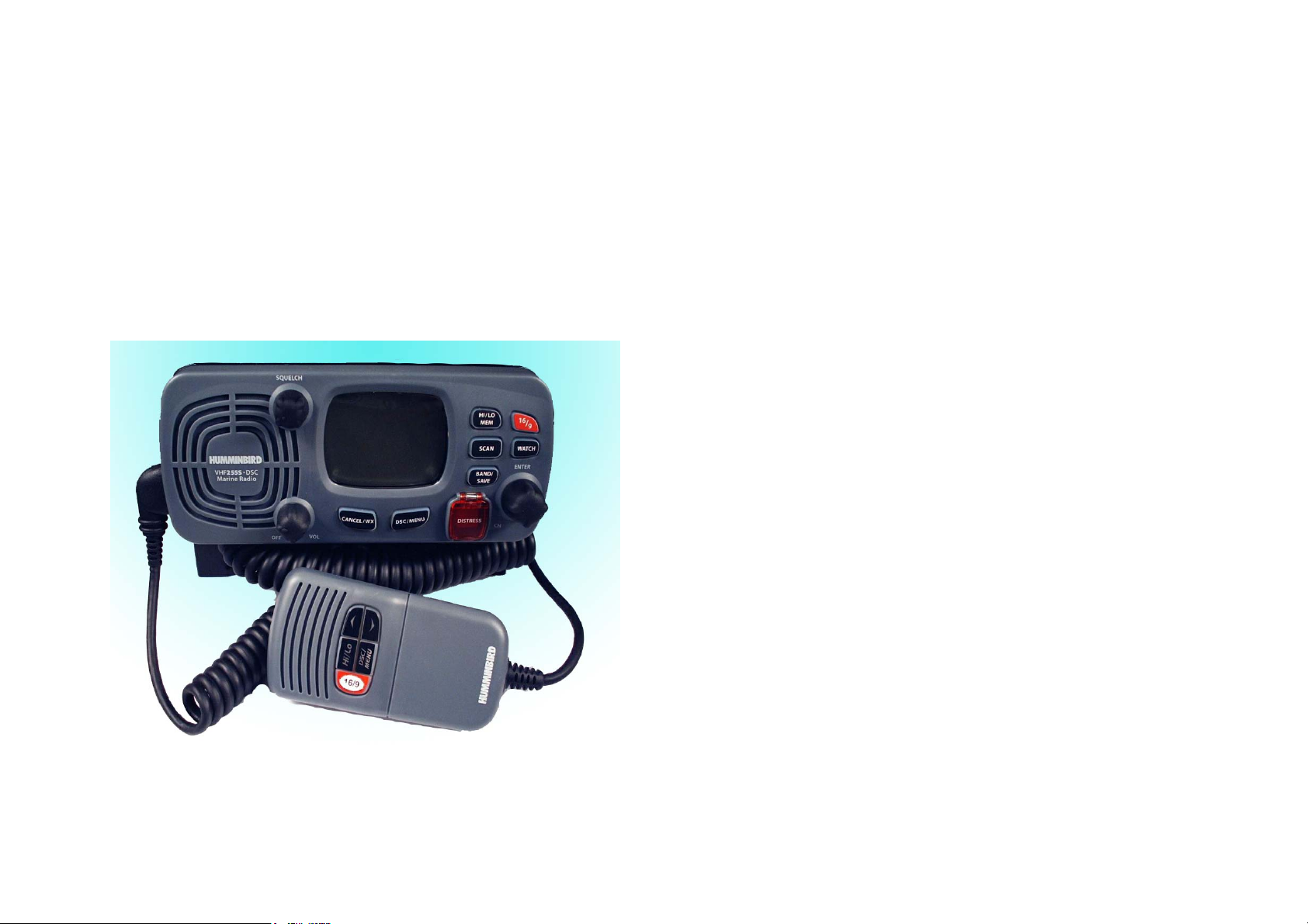
Congratulations on your purchase of Radio HUMMINBIRD VHF255S
DSC marine band radio. VHF255S is a VHF DSC Base Station Radio with output
power of 25/1 watt. It should be powered by a 13.8VDC power supply.
The radio can support DSC (Digital Selective Calling) operation with specially
designed DSC unit, which meets the standard of ITU-R, M493-10. When being
connected with GPS, it will display the position (longitude and latitude) of the
vessel. Compact fist microphone makes for convenient operation of the
equipment
Other features of the radio includes:
Access to all available INTL USA CANADA channels (currently allocated).
Allows up to all channels be used as memory channels for quick recall and
memory scan.
Provides as many as 20 user programmable names with MMSI, 10 distress
calls and 20 individual calls for DSC communications.
Rotary volume control with power on/off, rotary channel selector and rotary
squelch adjustable knob give you more convenient operation of the radio.
Outstanding performance of waterproof complying with Japanese Industry
Standard level 7.
25 watts high output power allows you make contact with others in a long
distance of marine communication; and 1watt low power for short distance.
Separate 169button, for quick selection of the emergency call on CH16.
Adjustable brightness of backlit for good visibility of the large LCD in various
circumstance,
External interface easy to connect to GPS and external speaker.
Mounting gimbal for firm and reliable location of your base station in
difference condition.
Page 5 Page 6
2 CONTROLS AND LCD DISPLAY
②
①
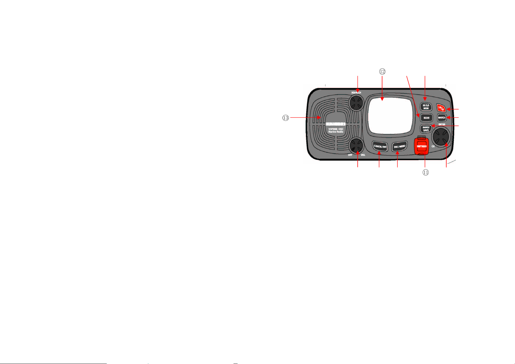
2.1 BASE STATION (PANEL)
Volume and Power On/Off① 0-270°rotary control knob. Turn clockwise to
Squelch② Use this knob to set the squelch threshold,
CH/enter③ Rotary encoder (no stop) with momentary push
` Rotate this knob to change the current number
Band / Save④ Select band (USA. INT and CAN) and set
⑤ Cancel/wx The key to cancel last selection or change
⑤
power on. Continue to turn until a comfortable
audio level.
which cuts off the receiver when the signal is
too week for reception of anything but noise.
and change values in menu mode or during
programming. Press the knob to enter values
memory channels
without saving. It allows step back one level on
menu mode. It cancels DSC Distress calls &
auto-retransmission of DISTRESS calls. Hold
the key entry wx mode
⑧
⑥
⑦
③
⑩
⑨
④
DSC /menu⑥ Use this key to enter Menu Setup or DSC Call Menu.
Call Mode is used for making DSC Calls. Menu Mode is
used to setup the radio.
⑦ Hi/Low/mem Press and release HI/LO button to toggle between
25watt power output and 1 watt output. “HI” or “LO” icon
appears on LCD display to indicate setting
Hold the key select memory channel mode
Scan⑧ Start and stop normal or priority scan and MEM
channels and priority channels scan.
Watch⑨ Start dual watch or tri-watch, Stop dual watch or tri-
watch.
16⑩ /9: Press and release 16/9 button to select channel 16 first;
further presses of 16/9 toggle between channels, press
16 key to quit all other modes and to into the channel of
priority.
DISTRESS This button is used to send a signal of distress in case
of emergency. See DSC Operation for details of
sending the call. This button is cover by a spring cover.
The Distress Function or any other transmitted DSC
function does not work unless a user’s MMSI has been
entered.
.
LCD: Large LCD (2“×1.5”) with viewable area of 4×12 dot
matrix makes it easy to be read.
Built-in Speaker Guarantee a clear ring and voice communication
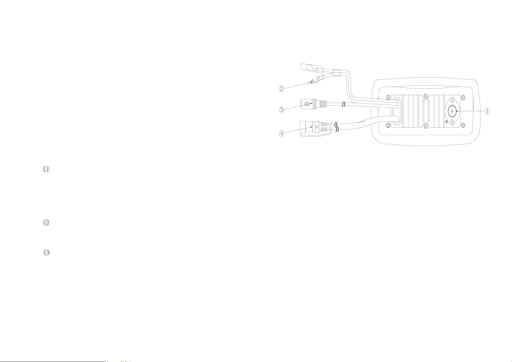
2.2 BASE STATION (REAR)
① Antenna Jack: Connect a suitable antenna to your marine VHF
radio to get a satisfying communication.
② Power Source Connect the radio to a 13.8 VDC power source.
③ External Speaker Connection Cable If need be, you can also use this
cable to connect an external speaker.
④ GPS Connector Connect the radio to a GPS receiver to acquire
the position and time information of your vessel
Page 7 Page 8
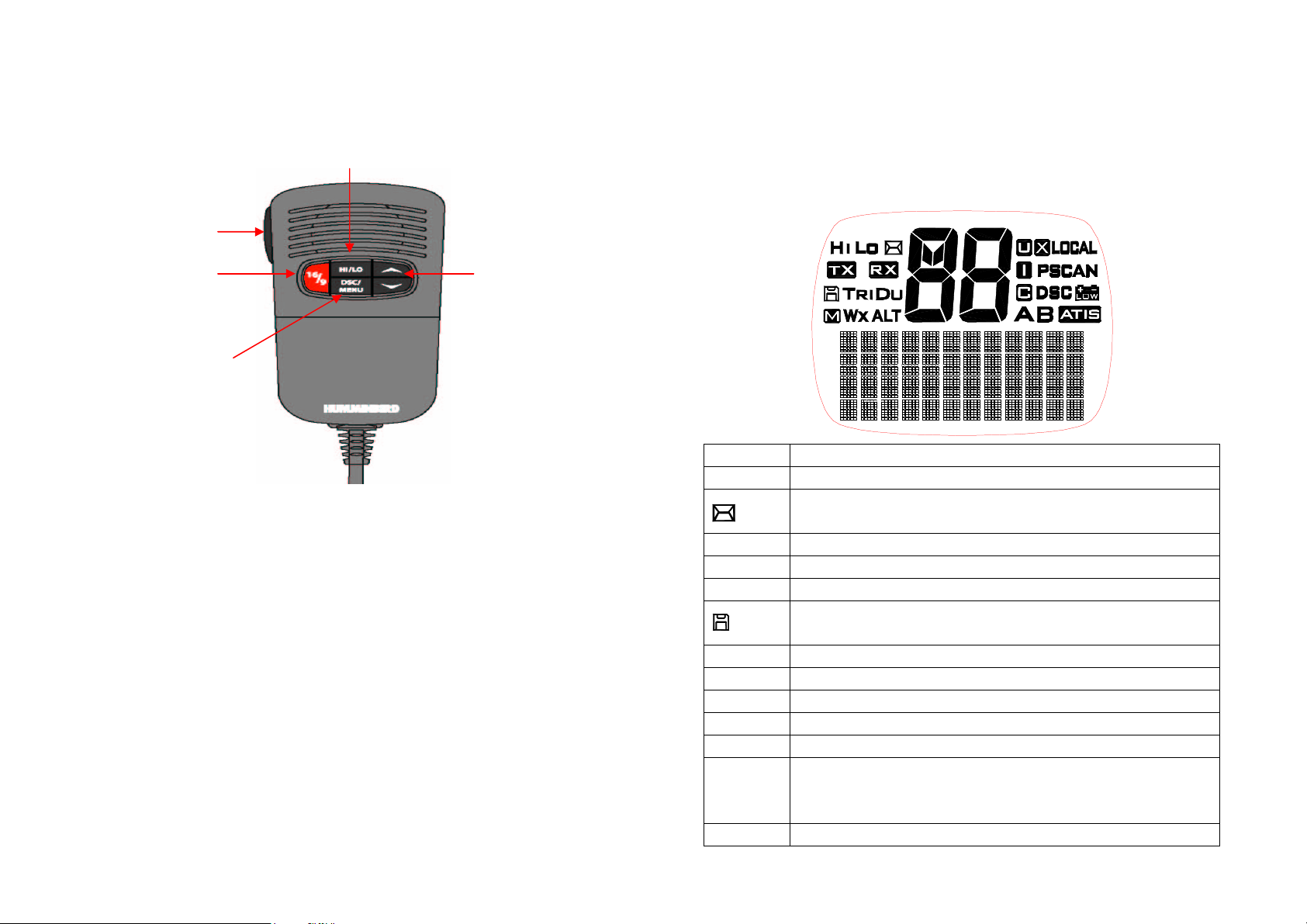
2.3 HANDSET
④
⑤
③
①②
① Channel Up/ Down Press and release to change channel.
② 16/9 Press and release 169 button to select channel
16 first; Press 16 key to quit all other modes and
to into the priority channel.
③ Hi/Low: Press and release HI/LO button to toggle
between 25watt power output and 1watt output.
The “HI” or “LO” icon appears on LCD display to
indicate the setting.
④ PTT: Push PTT to enable VHF communication into
transmitter.
.
Page 9 Page 10
⑤ DSC/MENU Use this button to enter Menu setup or DSC call
Menu Call Mode is used for making DSC Calls.
Menu Mode is used to setup the radio
2.4 LCD SYMBOL AND MEANINGS
SYMBOL MEANINGS
HI LO Transmission power High (HI) 25W or Low (LO) 1W.
TX Indicate that the radio is Transmitting
RX Indicate that the radio is receiving a radio signal.
M Indicate the current channel has been saved in memory.
DU TRI Indicate Watch state.
WX Weather channel mode is active. US and Canada
ALT an weather alert is being received. US and Canada
88 Channel selected.
U I C Selected channel bank for VHF radio operations and regulations.
LOCAL
PSCAN Indicate the current work on pri-scan mode.
Indicates an incoming DSC call or blank to notify you of any
unread call log messages.
Indicate the current work at Memory mode (Channel are selected
at saved channels).
Indicates the radio is in Local reception mode, which decreases
receiver sensitivity in high traffic areas to decrease unwanted
reception
SCAN Indicate the current work at the scan mode.
DSC DSC capability is available.
Battery Low indicates vessel battery voltage is low.
A B Channel suffix, if applicable.
ATIS Enable for use In European in inland waterway other wise blank
Dot Matrix Display indicates special conditions or radio functions.
3 INSTALLATION
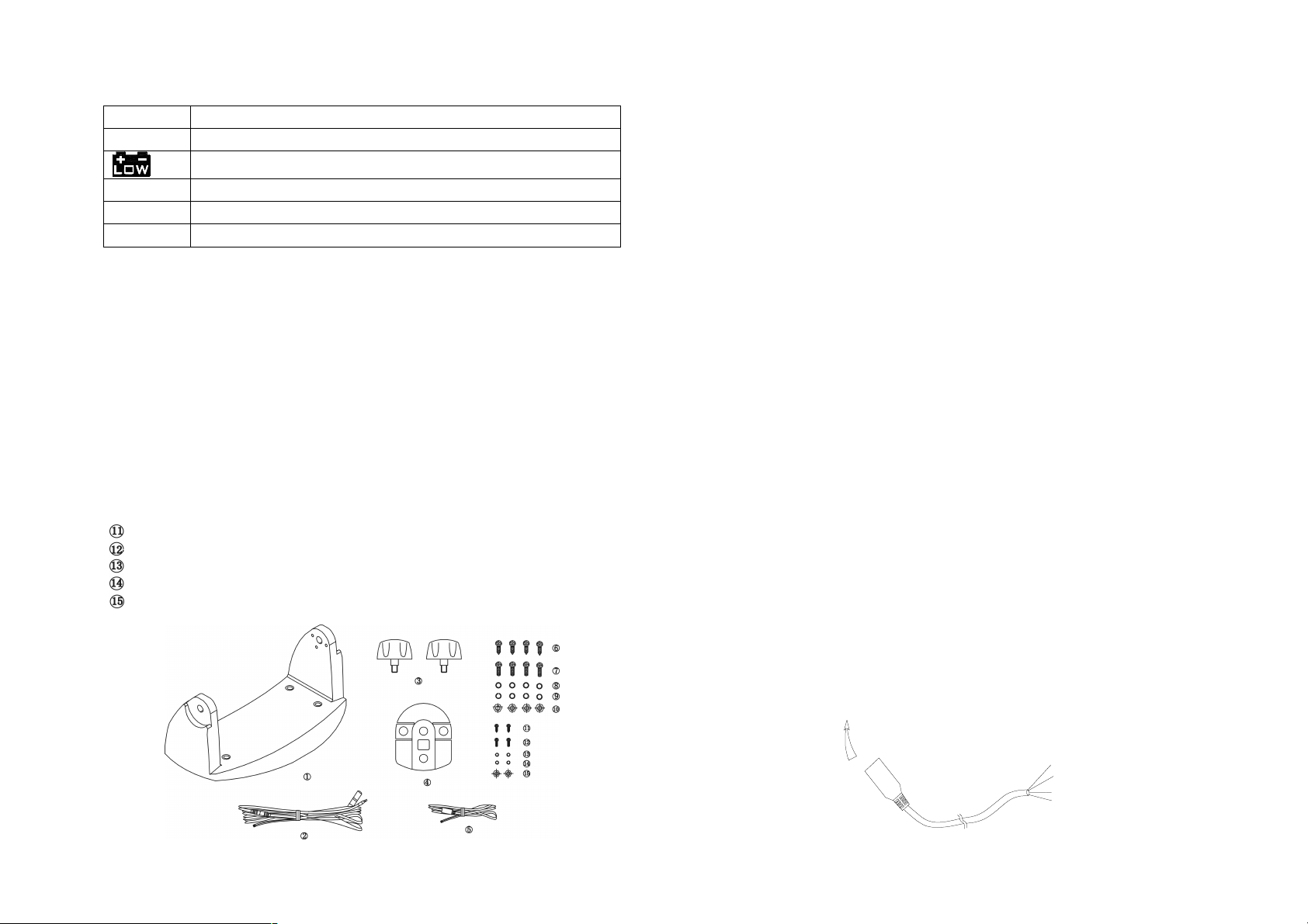
3.1 SUPPLIED ACCESSORIES
Manufacturer supplies you the following accessories as soon as you purchase
this ***** radio:
① Mounting gimbals (1 set)
② Power Supply Cable and External Speaker Connection Cable (1 set)
③ Mounting Knob (2 pcs)
④ Wall Hanger (1 pcs)
⑤ GPS Connection Cable (1 set)
⑥ Self-tapping Screw for Fixing Mounting Gimbals (4 pcs)
⑦ Flat Screw for Fixing Mounting Gimbals (4 pcs)
⑧ Plain Washer (4 pcs)
⑨ Spring Washer (4 pcs)
⑩ Nut (4 pcs)
Self-tapping Screw for Fixing Wall Hanger (2 pcs)
Flat Screw for Fixing Wall Hanger (2 pcs)
Plain Washer (2 pcs)
Spring Washer (2 pcs)
Nut (2 pcs)
3.2 LOCATION
To more conveniently and efficiently use your marine radio, find a mounting
location that:
Is far enough from any devices like devices to avoid any interference
caused by the speaker magnet in your radio during their operation;
Provides accessibility to the front panel controls;
Allows connection to a power supply and an antenna;
Has free space nearby for installation of a handset hanger;
Where the antenna can be mounted at least 3 feet from radio.
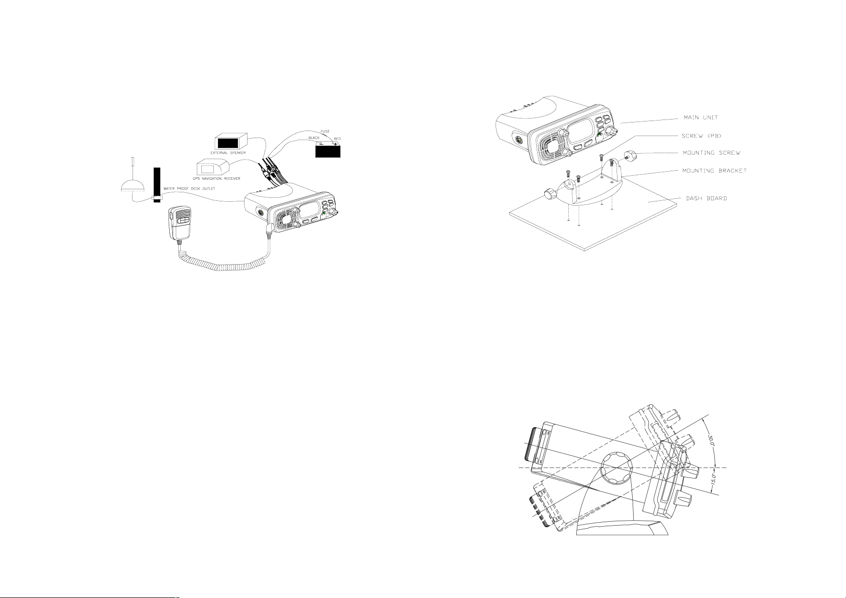
3.3 CONNECTIONS
POWER SUPPLY
You radio should be powered by a 13.8VDC power supply. Red cable is for
positive pole and the thicker black one is for negative pole.
EXTERNAL SPEAKER
If needed, you can connect your radio to an external speaker with the supplied
connection cable. White cable is for positive pole and the thinner black one is for
negative pole.
GPS EQUIPMENT
When your marine radio *** is connected by the GPS cable to a GPS equipment,
it can obtain the information of both its current location (longitude and latitude)
and the local GMT.
GPS CABLE
NMEA IN (+) from GPS navigation receiver, pin3. Yellow.
NMEA IN (-) from GPS navigation receiver, pin4. Green.
NEMA 0183 Version (1.5 to 3.0) input Sentences:
The sentences GLL, GGA, RMS, GNS shall be recognized.
Note: never short wires. This may lead to malfunctions.
Connecting: GPS cable round plug to radio and the wire of yellow and
the green connect to GPS navigation receiver.
To VHF255S.DSC
YELLOW
GREEN
ORANGE
BLACK
Page 11 Page 12
ANTENNA
A very important part for the performance of any communication system is a
suitable antenna. Consult your dealer about antennas and ask them to help to
mount your radio.
9. Attach the supplied mounting knobs from the two sides of the bracket to
fixing the base station securely.
3.4 MOUNTING THE RADIO
Mount the radio on your vessel:
1. Find a appropriate location defined in section 3.2;
2. Place the mounting bracket on the location surface, use a pencil to mark the
location of four holes where the fixing screws are to go into;
3. Caution: Be careful tot to drill through the mounting surface.
4. Remove the bracket, drill four holes smaller than the screw diameter, then
re-place the mounting bracket on the surface aligning the drilled holes;
10. Caution: Keep the radio and handset at least 1 meter away from any magnetic
devices such as compass on your vessel.
The supplied universal mounting bracket allows you to mount your base
station from overhead or on dashboard with a big scope of angle as many
0
.
as 45
Change the angle after installation:
11. Loosen the mounting knob at the sides of gimbal first.
12. Then adjust the base station to an appropriate direction with matching of the
protuberances on the inner sides of gimbal and pits on the outer sides of
base station.
13. Tighten the knob to secure.
5. Insert the four fixing screws and secure the bracket to mounting surface
using the supplied bolts, spring washers, plain washers and nuts;
6. Caution: if you can not reach behind the mounting surface to attach the nut on
the bolts, use the supplied self-tapping screws to fasten the bracket.
7. Insert the four fixing screws and fasten them with a Philip screw driver with
attention not to screw too tightly;
8. Mount the base station onto the bracket with notice of the matching of the
protuberances on the both inner side of the bracket and the pits on the two
sides of the base station (the selectable pits on the sides of the radio allow
you adjust the direction of the radio face to satisfy your easy-to-read-anduse, 150 for each rotation and totally 450 tolerance);
Page 13 Page 14
 Loading...