

Page 1
Tekcom
Owner’s Manual
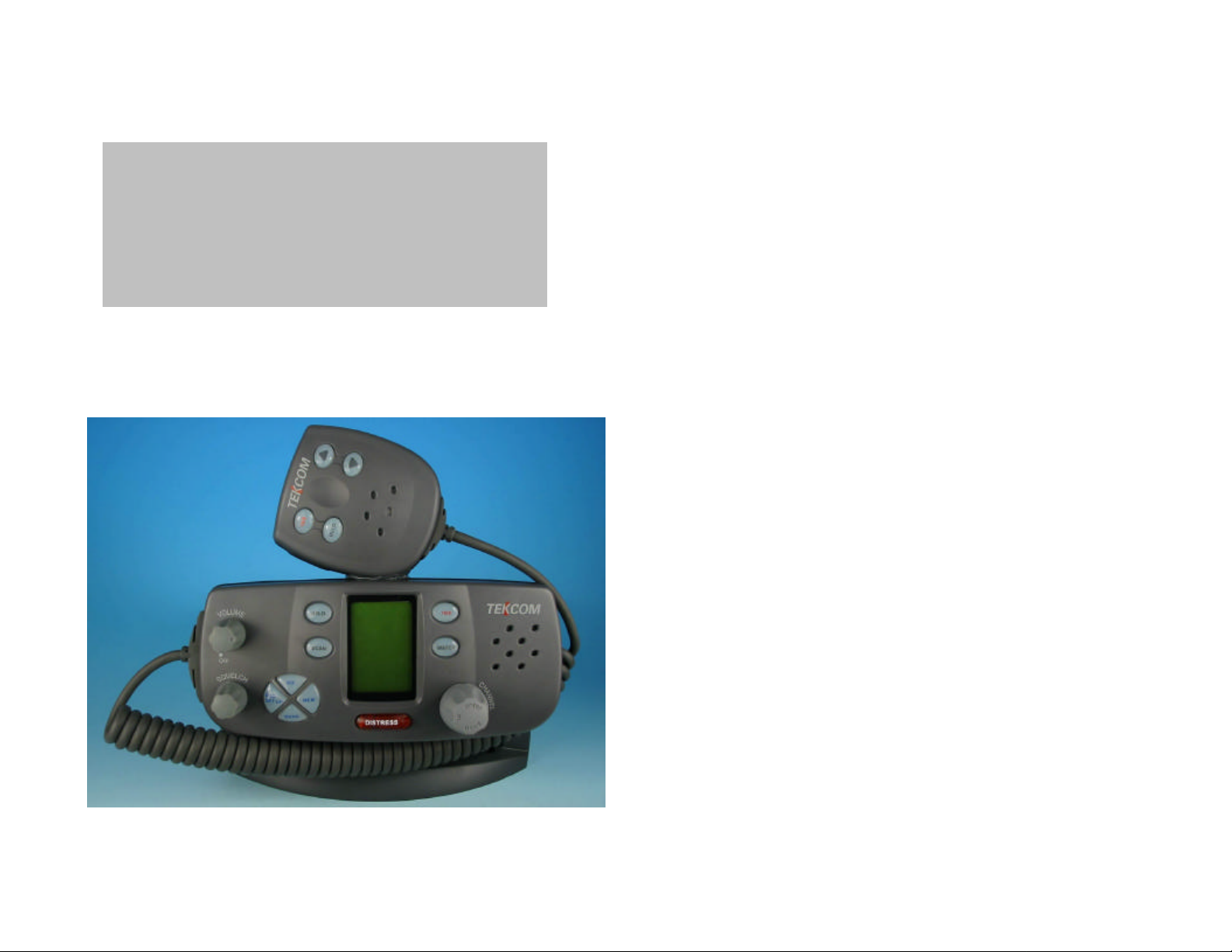
TM-338 Marine Radio
25/1 Watt VHF/FM Marine Radio
TM -338UD Date: Jan 7,03
OPERATOR WARNING
TEKCOM requires the radio operator to meet the requirements for Radio
Frequency Exposure. Unauthorized changes or modifications to this
equipment may void compliance with ETSI Rules. Any changes or
modification must be approved in writing by TEKCOM Corp.
This equipment has been tested and licensed to comply with the limits for
Class D Digital Marine Devices. These limits are designed to provide
reasonable protection against harmful interference in a residential
installation. This equipment can generate or radiate radio frequency
energy and, if not installed and used in accordance with the instructions,
may cause harmful interference to radio communications and human
body. Never transmit before you make sure the antenna is properly
located.
This device is only an aid to navigation. Its performance may be affected
by many factors: including equipment failure or defects, environmental,
and improper handling or use. It is the user's responsibility to exercise
common prudence and navigational judgement, and this device should
not be relied upon as a substitute for such prudence and judgement.
Your TEKCOM VHF radio generates and radiates radio frequency (RF)
electromagnetic energy (EME). This equipment must be installed and
operated in accordance with the instructions contained in this handbook.
Failure to do so can result in personal injury and/or product malfunction.
Page 2

TABLE OF CONTENTS
1. EQUIPMENT DESCRIPTION………………………………………1
Introduction………………………………………………………………..1
ETSI Information…………………………………………………………2
2. CONTROLS AND LCD DISPLAY…………………………………3
Controls and Connections 3
Base Station (Panel)
Base Station (Rear)
Handset…………………………………………………………………7
Liquid Crystal Display……….……….. ……..……………………………8
3. INSTALLATION ………………………………………………..……9
Supplied Accessories……………………………………………………9
Location……………………………………………………………………10
Connections…………………………….………….……………………10
Mounting the Radio…………………………..…………………………11
Antenna Mounting/The EME Exposure……..…………………………13
Mounting the Handset…………………………..………………………14
4. BASIC OPERATION………………………………………..……15
Channel Selection………………………..………………………………15
Transmission and Reception……………………………………………16
Modes Description………………………………………………………16
Function Description……………………………………………………17
Position Indication………………………………………………………18
3
……………………………………………………6
DIGITAL SELECTIVE CALLING…………………………………19
Introduction………………………………………………………………..19
.
DSC Menu Navigation…………………………………………………19
Sending a DSC Call…………………...…………………………………19
Receiving a DSC Call 26
5. ET-UP MENUS……………………………………………………29
Description……………………………………………………………...29
DSC Mode Adjustment………………………………………………...30
Call Log Operation…………………………….…………………………31
Backlight Adjustment………………………….…………………………31
Buddy List Entry……………………………….…………………………32
Delete Buddy List………………………………………………………33
Position……………………………………………………………………33
UTC Time………………………………………………………………..34
Contrast Adjustment……………………………………………………..34
Key Beep Adjustment……………………………………………………35
Time Offset Adjustment…………………………………………………35
User MMSI Entry…………………………………………………………35
Group MMSI Entry……………………………………………………36
Reset Operation………………………………………………………….37
6. MAINTENANCE………………………………………………….…39
7. SPECIFICATION…………………………………………………40
8. CHANNEL LIST…………………………………………………….41
Page 3

EQUIPMENT DESCRIPTION
1.1 INTRODUCTION
Congratulations on your purchase of TEKCOM’s *** marine band radio. *** is a
VHF DSC Base Station Radio with output power of 23/1 watt. It should be
powered by a 13.8VDC power supply.
The radio can support DSC (Digital Selective Calling) operation with specially
designed DSC unit, which meets the standard of ITU-R, M493-9. When being
connected with GPS, it will display the position (longitude and latitude) of the
vessel. Compact fist microphone makes for convenient operation of the
equipment
Other featur es of the radio includes:
l Access to all available International channels (currently allocated).
l Allows 10 memory channels for quick recall and memory scan.
l Provides as many as 20 user programmable names with MMSI, 10 distress
calls and 20 individual calls for DSC communications.
l Rotary volume control with power on/off, rotary channel selector and rotary
squelch adjustable knob give you more convenient operation of the radio.
l Outstanding performance of waterproof complying with Japanese Industry
Standard level 7.
l 23 watts high output power allows you make contact with others in a long
distance of marine communication; and 1 watt low power for short distance.
l Separate 16 button, for quick selection of the emergency call on CH16.
l Adjustable brightness of backlit for good visibility of the large LCD in various
circumstance.
l External interface easy to connect to GPS and external speaker.
l Mounting gimbal for firm and reliable location of your base station in
different conditions.
l Warning: This equipment is designed to generate a digital maritime distress
and safety signal to facilitate search and rescue. To be effective as a safety
device, this equipment must be used only within communication range of a
shore-based VHF marine channel 70 distress and safety watch system. The
range of the signal may vary but under normal conditions should be
approximately 20 nautical miles.
Page 1 Page 2
Page 4
CONTROLS AND LCD DISPLAY
2.1 CONTROLS AND CONNECTIONS
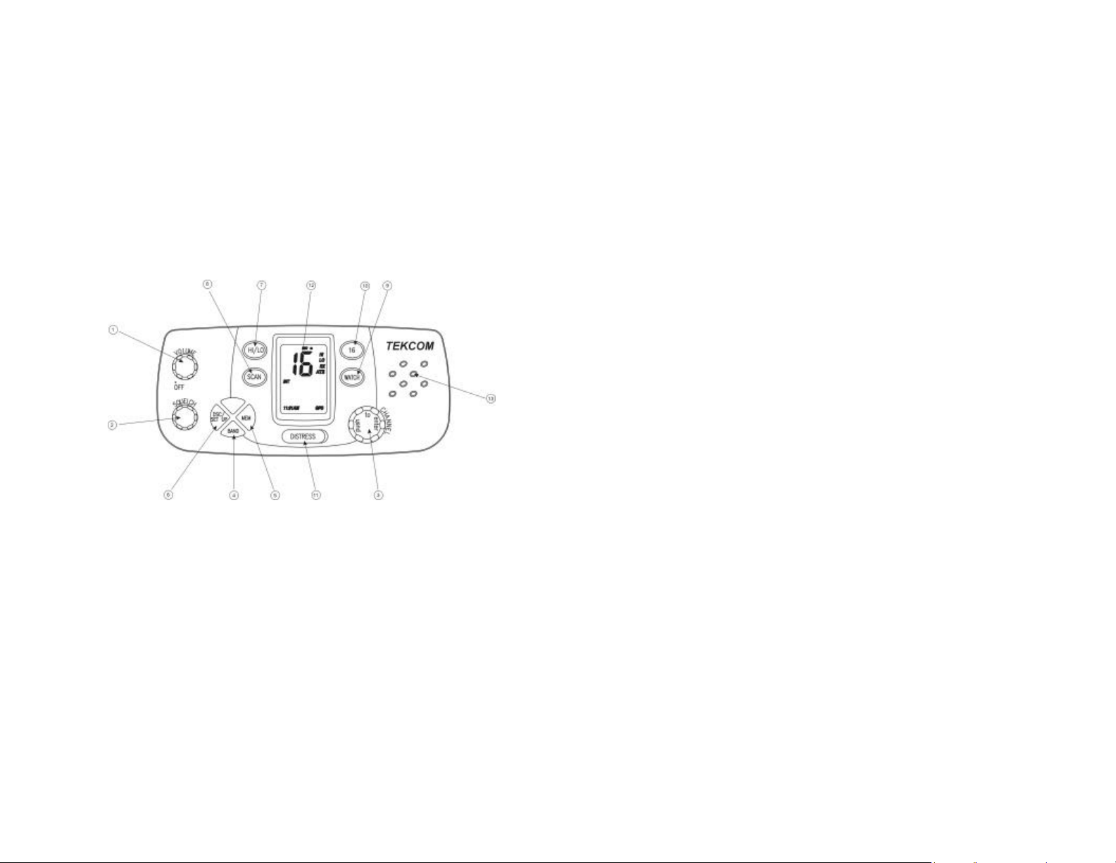
2.1.1 BASE STATION (PANEL)
Volume and On/Off Knob 0-270° rotary control Power off at Zero
?
Degree.
? Squelch knob 0 -270° rotary control.
? Channel/Select/enter Rotary encoder (no stop) with momentary
`
In VHF (USA or INT), WX, and MEM mode,
In DSC Mode and Set-Up (in Channel 70
push
the default operation selects channels in the
active band. With the knob is rotated the
channel is displayed on the LCD Display
Selected), the default rotary operation selects
(using an arrow ">") from menu items on screen,
and the momentary push action enters the
selected item. See DSC Operation for detailed
description.
Band: Press and release BAND button to enter normal
?
WX: Press and release to select Weather channel
When in WX mode, further WX key presses have
VHF Mode (USA and INT bands). Successive
press and release toggles between USA and INT
band.
mode.
When in WX mode, the radio continually monitors
the active weather channel for the NOAA weather
alert tone. The "Cloud" icon appears on the
display to indicate that NOAA weather alert is
functioning and a subsequent alert tone.
no effect.
? Memory: Press and release for less than 1 second to select
Memory Mode. “MEM” characters appear on the
display indicate Mode of operation. While in
memory mode channel knob selects from memory
channels programmed into the radio.
? DSC: Press and release to select DSC Mode. Channel
70 is automatically selected, and the Send Call
Menu appears on the display. See DSC
Operation for complete description of DSC
function.
? Hi/Low: Press and release HI/LO to toggle between 23
Watt power output and 1 watt output. “HI” or “LO”
icon appears on LCD display to indicate setting.
Page 3 Page 4
Page 5
? Scan: Pressing and releasing SCAN button (for less
than 1 second) to activate scanning. Scan mode
is either in Normal (Scan 1,2,3,4...) or Priority
(Scan 1,16,2,16,3,16...) depending on user’s
programming. A text appears on the display to
indicate the Scan Function is active. When the
scan function is active, press and release SCAN
button to deactivate scan function.
? Dual/Tri Watch: Press and release WATCH button (for less than 1
second) to activate dual or tri-watch function
depending on user programming. Characters
appear on the display to indicate each watch
function. When dual or tri watch is active, press
WATCH button to deactivate.
? 16/9: Press and release 16/9 button to select channel
16 first; further presses of 16/9 toggle between
channels 16 and 9.
Distress: Press and release the DISTRESS button to send
a DSC Distress call. MMSI and Nature of
Distress are included in the signal. Position and
time are included in the broadcast if appropriate
NMEA data is available. See DSC Operation for
details of sending the call. (According to EN 301025, this button is covered by a spring loaded
cover)
The Distress Function or any other
TRANSMITTED DSC function does not operate
unless a user’s MMSI has been entered.
LCD: Large LCD (1“ ×1.5”) with viewable area of 4×12
dot matrix makes it easy to be read.
Built-in Speaker: Guarantees a clear ring and voice
communication.
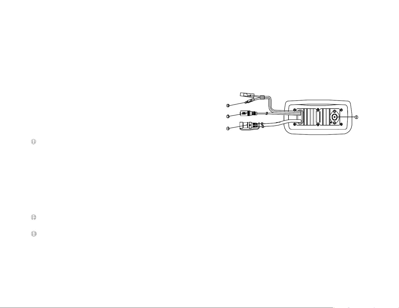
2.1.2 BASE STATION (REAR)
? Antenna Jack: Connects a suitable antenna to your marine VHF
radio to get a satisfying communication.
? Power Source: Connects the radio to a 13.8 V DC power source.
? Jack socket for external speaker : If need, you can also use this cable to
Connect an external speaker.
? GPS connect Connects the radio to a GPS receiver to acquire
the position and time information of your vessel.
Page 5 Page 6
Page 6
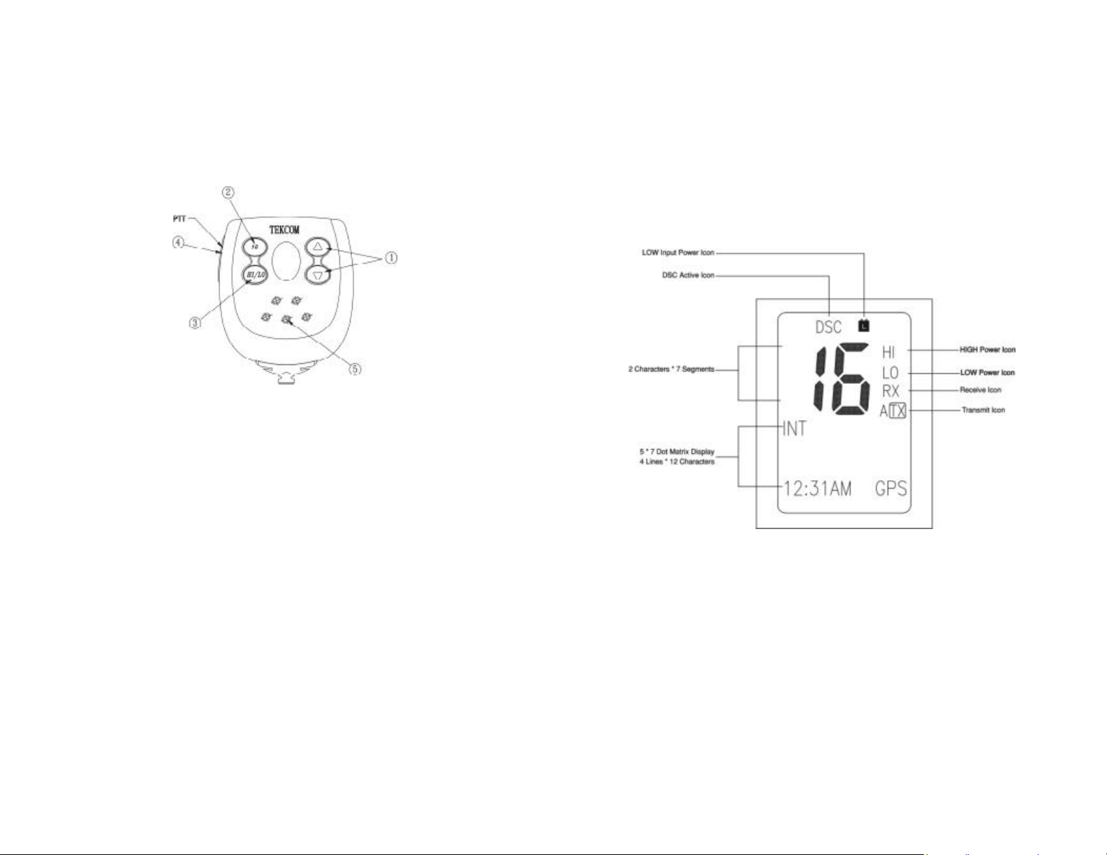
2.1.3 HANDSET
? Channel Up/Channel Down: 2 Keys, press and release to change channel.
? 16:/9 Press and release 16/9 button to select channel
16 first; further presses of 16/9 toggle between
channels 16 and 9.
? Hi/Low: Press and release HI/LO button to toggle
between 23 Watt power output and 1 watt output.
“HI” or “LO” icon appears on LCD display to
indicate the setting.
? PTT: Push to enable VHF communication through the
23/1-Watt transmitter.
? Internal Microphone: Well receive your voice information and ensure a
reliable communication.
2.2 LIQUID CRYSTAL DISPLAY
Page 7 Page 8
Page 7
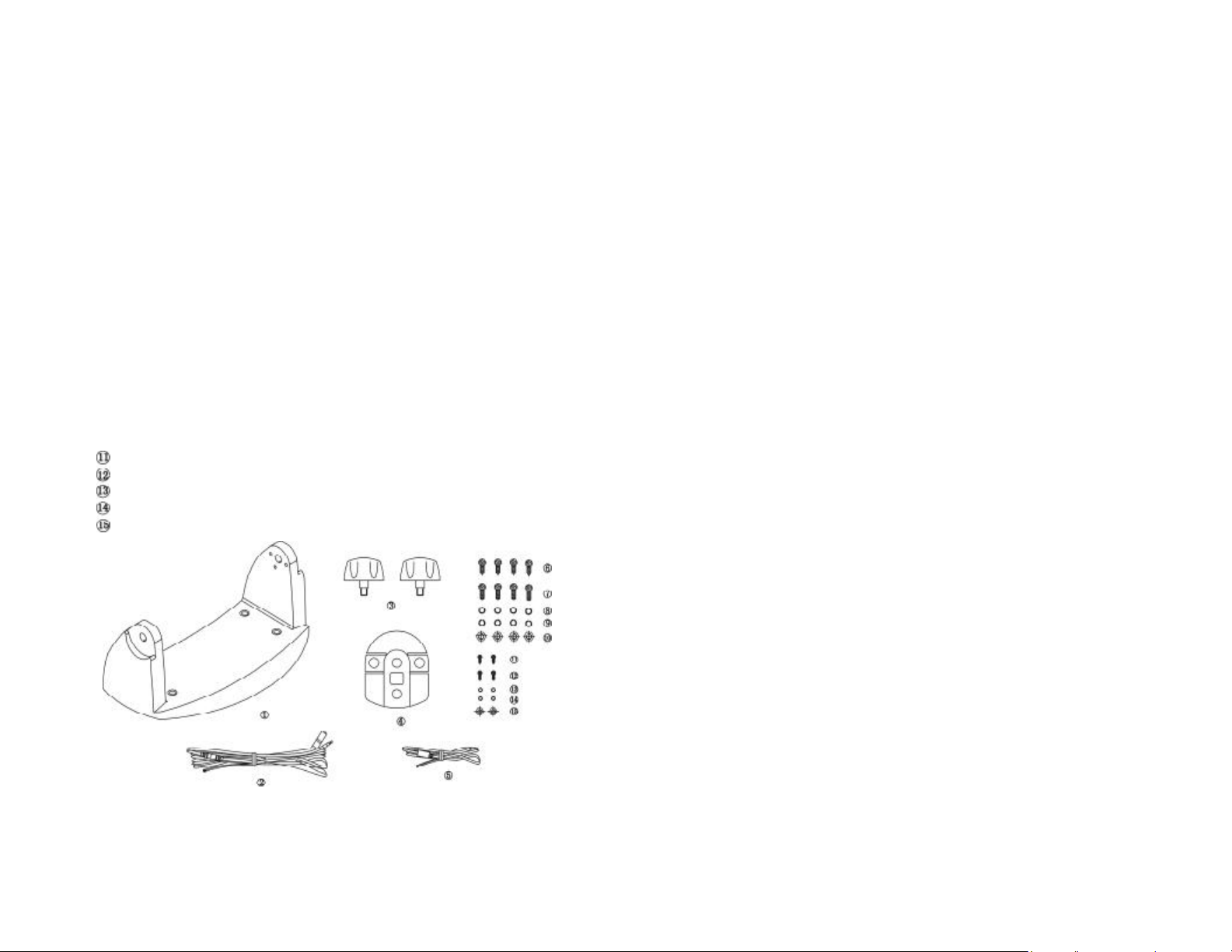
INSTALLATION
3.1 SUPPLIED ACCESSORIES
Manufacturer supplies you the following accessories as soon as you purchase
this *** marine radio:
? Mounting Gimbal (1 set)
? Power Supply Cable and External Speaker Connection Cable (1 set)
? Mounting Knob (2 pcs)
? Wall Hanger (1 pcs)
? GPS Connection Cable (1 set)
? Self-tapping Screw for Fixing Mounting Gimbal (4 pcs)
? Flat Screw for Fixing Mounting Gimbal (4 pcs)
? Plain Washer (4 pcs)
? Spring Washer (4 pcs)
? Nut (4 pcs)
? Self-tapping Screw for Fixing Wall Hanger (2 pcs)
? Flat Screw for Fixing Wall Hanger (2 pcs)
? Plain Washer (2 pcs)
? Spring Washer (2 pcs)
? Nut (2 pcs)
3.2 LOCATION
To more conveniently and efficiently use your marine radio, find a mounting
location that:
l Is far enough from any compass like devices to avoid any interference
caused by the speaker magnet in your radio during their operation;
l Provides accessibility to the front panel controls;
l Allows connection to a power supply and an antenna;
l Has free space nearby for installation of a handset hanger;
l Where the antenna can be mounted at least 3 feet from radio.
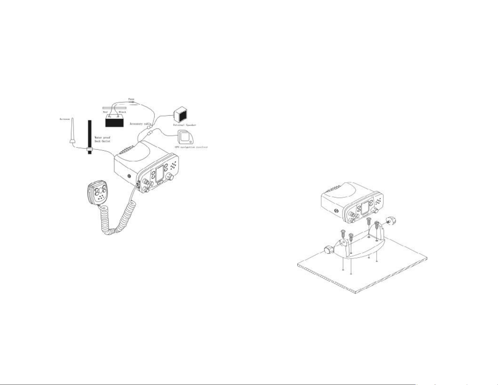
3.3 CONNECTIONS
POWER SUPPLY
You radio should be powered by a 13.8VDC power supply. Red cable is for
positive pole and the thicker black one is for negative pole.
EXTERNAL SPEAKER
If need, you can connect your radio to an external speaker with the supplied
connection cable. White cable is for positive pole and the thinner black one is for
negative pole.
GPS EQUIPMENT
When your marine radio *** is connected to a GPS equipment, it can obtain the
information of both its current location (longitude and latitude) and the local GMT.
(“+” yellow, “-“ green)
Page 9 Page 10
Page 8
ANTENNA
A very important part for the performance of any communication system is a
suitable antenna. Consult your dealer about antennas and ask the m to help best
mount to your radio.
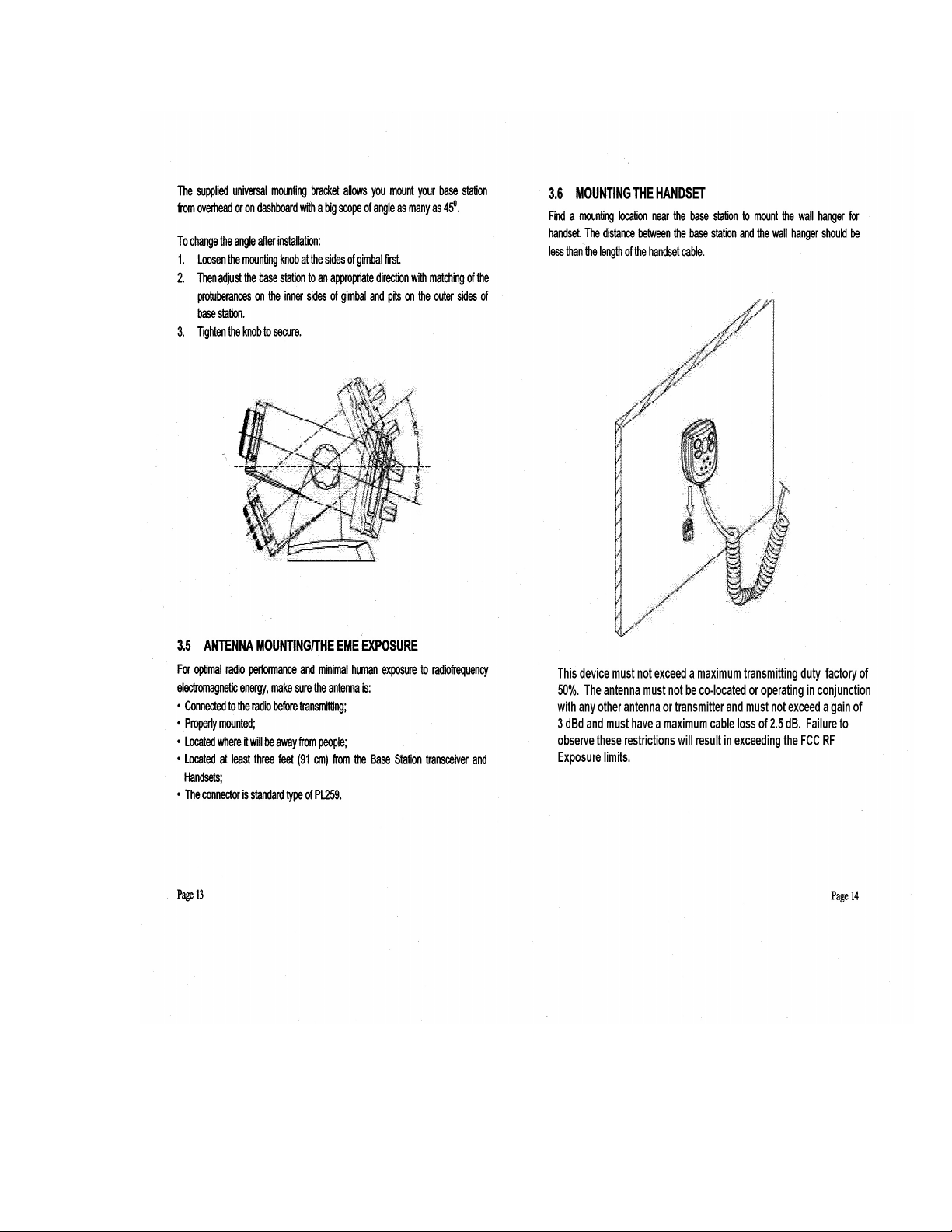
3.4 MOUNTING THE RADIO
To mount the radio on your vessel:
1. Find a appropriate location defined in section 3.2;
2. Place the mounting bracket on the location surface, use a pencil to mark the
location of four holes where the fixing screws is to go into;
L Caution: Be careful to not drill through the mounting surface.
3. Remove the bracket, drill four holes smaller than the screw diameter, then
re-place the mounting bracket on the surface aligning the drilled holes;
4. Insert the four fixing screws and secure the bracket to mounting surface
using the supplied bolts, spring washers, plain washers and nuts;
L Caution: if you can not reach behind the mounting surface to attach the nut on
the bolts, use the supplied self- tapping screws to fasten the bracket.
5. Insert the four fixing screws and fasten them with a Philip screw driver with
attention not to screw too tightly;
6. Mount the base station onto the bracket with notice of the matching of the
protuberances on the both inner side of the bracket and the pits on the two
sides of the base station (the selectable pits on the sides of the radio allow
you adjust the direction of the radio face to satisfy your easy-to-read-anduse, 150 for each rotation and totally 450 tolerance);
7. Attach the supplied mounting knobs from the two sides of the bracket to
fixing the base station securely.
L Caution: KEEP the radio and handset at least 1 meter away from any magnetic
devices such as compass on your vessel.
Page 11 Page 12
Page 9
Page 10

BASIC OPERATION
After the radio has been installed, make sure of the power supply and antenna
being properly connected. Rotate the VOLUME/POWER knob clockwise to turn
on the radio and select a comfortable volume level. Turn the SQUELCH knob
clockwise until the background noise disappears.
4.1 CHANNEL SELECTION
USA and INT Channels
There are altogether 51 USA and 55 International channels listed in the channel
list section. These channel groups may be specified for the operating area. To
select the desired channel:
1. Press BAND button to enter the VHF mode;
2. In VHF mode, rotate CHANNEL/SELECT knob to select channel in the
active band. With the knob being rotated, the channel is displayed on the
LCD display;
J Note: On base station, slightly rotate the CHANNEL/SELECT knob for one level,
the channel will advance or return backward for one channel, accompanied by a
beep sound. You can also press UP or DOWN button to get the desi red channel;
if you want to quick skim channels, just press and hold down the UP or DOWN
button.
Memory Channels
You can store as many as 10 international channels as memory channels.
1. Press and release MEM button for less than 1 second to enter Memory
Mode. “MEMORY” characters appear on the display indicating the current
mode of operation.
2. Rotate the CHANNEL/SELECT knob to select from memory channels
programmed into the radio.
3.
Channel 16/9
Channel 16/9 is the distress and safety channel. It is used for establishing initial
contact with another station and for emergency communications. Channel 16 is
monitored during dual watch. While Key 16/9 gives you a quick access to the
channel 16.
4.2 TRANSMISSION AND RECEPTION
L CAUTION: Transmitting without an antenna may damage the radio.
1. Press the PTT (Push- To-Talk) button on the handset, the TX indicator on
LCD is displayed.
2. Speak clearly in a normal voice into the microphone.
3. When the transmission is finished, release the PTT button.
4.
4.3 MODES DESCRIPTION
Band: Press and release BAND button to enter normal VHF
Mode (USA and INT bands). When pressed, the
current band selection is indicated on the LCD by text.
When returning to VHF mode from either DSC or MEM
mode, the selected band is the last active international
channel. This setting is stored in NVM (non-volatile
memory).
Memory: Press and release MEM button for less than 1 second
to select Memory Mode. “MEMORY” characters
appear on the display indicating the mode of operation.
While in memory mode, channel knob selects from
memory channels programmed into the radio.
When radio is in normal VHF Mode, press and hold
MEM button for 1 second or greater to remember
current channel and band as a memory channel.
Channels are remembered in sequence entered.
When a memory channel is stored, the key MEM for 1
second or greater will remove the channel from
memory.
DSC: Press and release to select DSC Mode. Channel 70 is
automatically selected, and the Send Call Menu
Page 15 Page 16
Page 11

appears on the display. See DSC Operation for
complete description of DSC function.
Distress: Open the protection cover, then press and release the
DISTRESS button to enter distress Mode. Channel 70
is automatically selected with high power, and the
Send Call Menu appears on the display. See Distress
Operation for complete description of distress function.
4.4 FUNCTION DESCRITION
High/Low: Press and release HI/LO to toggle between 23 Watt
power output and 1 watt power. “HI” or “LO” icon
appears on LCD display to indicate the setting.
When radio is tuned to channels restricted to low
power output, pressing HI/LO key overrides the low
power setting ONLY if permissible in FCC guidelines.
High/Low functions in the normal VHF Mode or MEM
Mode. In DSC mode HI/LO key has no function and
will produce an er ror tone when being pressed.
Scan: Pressing and releasing SCAN button (for
less than 1 second) to activate scanning.
Scan mode is either in Normal (Scan
1,2,3,4...) or Priority (Scan 1,16,2,16,3,16...)
depending on user’s programming. A text
appears on the display to indicate the Scan
Function is active. When the scan function is
active, press and release SCAN button to
deactivate scan function.
When radio is in Memory Mode, memory
channels are scanned. When in normal VHF
(USA, INT) Mode, channels in the selected
band are scanned. When in WX Mode,
weather channels are scanned. When in
DSC Mode, scan has no function and an
error tone is produced.
Pressing and holding SCAN button for greater
than 1 second toggles the Scan Function between
normal and priority scan. When the scan
programming function changes, an audible tone is
produced and the alternative selected Scan
Function momentarily appears on the LCD in the
Text Area, written as "PRI- SCAN" or "NORSCAN". The default setting is Priority Scan.
Dual / TRI Watch: Press and release WATCH button (for less than 1
second) to activate dual or tri-watch function
depending on user programming. Characters
appear on the display to indicate each watch
function. When dual or tri watch is active, press
WATCH button to deactivate.
Dual Watch monitors the working channel,
channel 16 and last tuned WX channel for the
NOAA weather alert signal. The ”Cloud” icon
appears on the display to indicate that NOAA
weather alert is functioning and an audible alert
tone is produced.
TRI Watch monitors the working channel, channel
16, channel 9 and the last tuned WX channel for
the NOAA weather alert signal. The ”Cloud” icon
appears on the display to indicate that NOAA
weather alert is functioning and an alert tone
audible is produced.
Pressing and holding WATCH for greater than 1
second toggles the Key Function between Dual or
Tri scan. When the key programming function
changes, an audible tone is produced and the
alternative selected Scan function momentarily
appears on the LCD in the Text Area, written as
"DUAL WATCH" or "TRI WATCH". The default
setting is Dual Watch.
Page 17 Page 18
Page 12
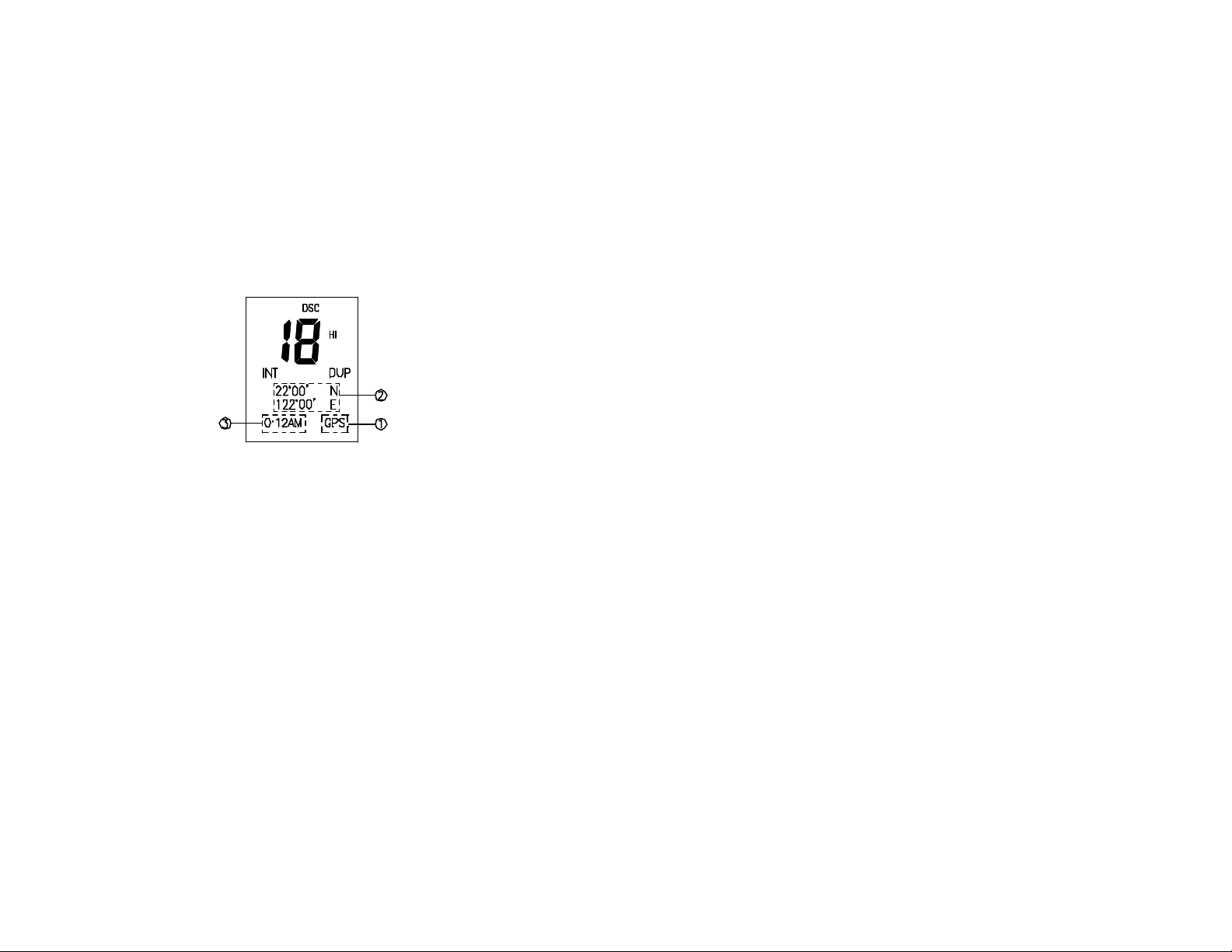
4.5 POSITION INDICATION
Your transceiver can display the position of the vessel’s (longitude and latitude)
as well as time and date information, if connected to a GPS receiver; if no GPS
equipment to be connected,an alert tone of 1- minute duration witch can cancelled
By any button is sounded at 4 hour intervals to encourage manual input of
positional data . Once no manual input is made for 23.5 hours, GPS disappears
from the screen, the position data transmitted goes to 9’s and all the time data
goes to 8’s.
1.GPS INDICATOR
“GPS” appears while GPS receiver is connected.
“GPS” disappears while no GPS receiver is connected.
2. POSITION INDICATOR
3.TIME INDICATOR
Shows the GPS time date or the time date is the radio’s clock time
Shows the GPS position data or the position data is input manually
“local” appears when the offset time date on the “set -up” menu are
entered. and no GPS re ceiver is connected
UTC” appears when the position date is input manually
@ NOTE : if GPS data is interrupted for 2 minute the radio unit on LCD display
‘PLEASE INPUT POSITION!‘ and an alert tone is sounded “GPS”
disappear. “UTC” appears instead of “GPS” at 1minute.Time go on
according to the radio unit’s clock
The position data retains the most recent date in such cases.
If no GPS receiver is connected. After to turn on power, LCD display
time go on according to the radio unit’ s clock time for 10 min LCD
display appears ”PLEASE INPUT POSITION” and the alert tone is
sounded to encourage manual input of the position
DIGITAL SELECTIVE CALLING
5.1 INTRODUCTION
5.1.1 DIGITAL SELECTIVE CALLING (DSC)
Digital Selective Calling is a semi-automated method of establishing a radio call,
it has been designated by the International Maritime Organization (IMO) as an
international standard for establishing VHF, MF and HF radio calls. It had also
been designated part of the Global Maritime Distress and Safety System
(GMDSS). It is planed that DSC will eventually replace aural watches on distress
frequencies and will be used to announce routine and urgent maritime safety
information broadcasts. This new service will also allow mariners to initiate or
receive distress, urgency, safety and routine calls to or from another vessel
equipped with a DSC transceiver.
5.1.2 MARINE MOBILE SERVICE INDENTITY (MMSI)
An MMIS is a nine digit number used on Marine Transceiver capable of using
Digital Selective Calling (DSC). This number is used like a telephone number to
selectively call other vessels. Refer to section 6.12 (USER MMSI ENTRY).
5.2 DSC MENU NAVIGATION
Once in DSC mode, the Channel/Select key is used to select items within the
DSC Send Call menu. Rotating the Channel/Select knob selects successive
items within the DSC Menu (and subsequent sub- menus). When the Menu list
contains more items than will fit on the LCD, the list scrolls to reveal additional
items. Pressing the Channel/Select knob enters (or acts) the selected function.
At any time while in DSC Mode, pressing and releasing the DSC key returns the
screen to the DSC Send Call menu and aborts the current operation. Pressing
any other mode key (BAND, MEM ) while in the DSC Mode aborts the DSC
Page 19 Page 20
Page 13
function (except a Distress Call) and changes to the Mode of operation
accordingly.
5.3 SENDING A DSC CALL
5.3.1 DISTRESS CALL
5.3.1.1 Sending a Distress Call
Distress calls are initiated with the following procedure:
1. Open the Distress cover.
2. Press the DISTRESS key momentarily .
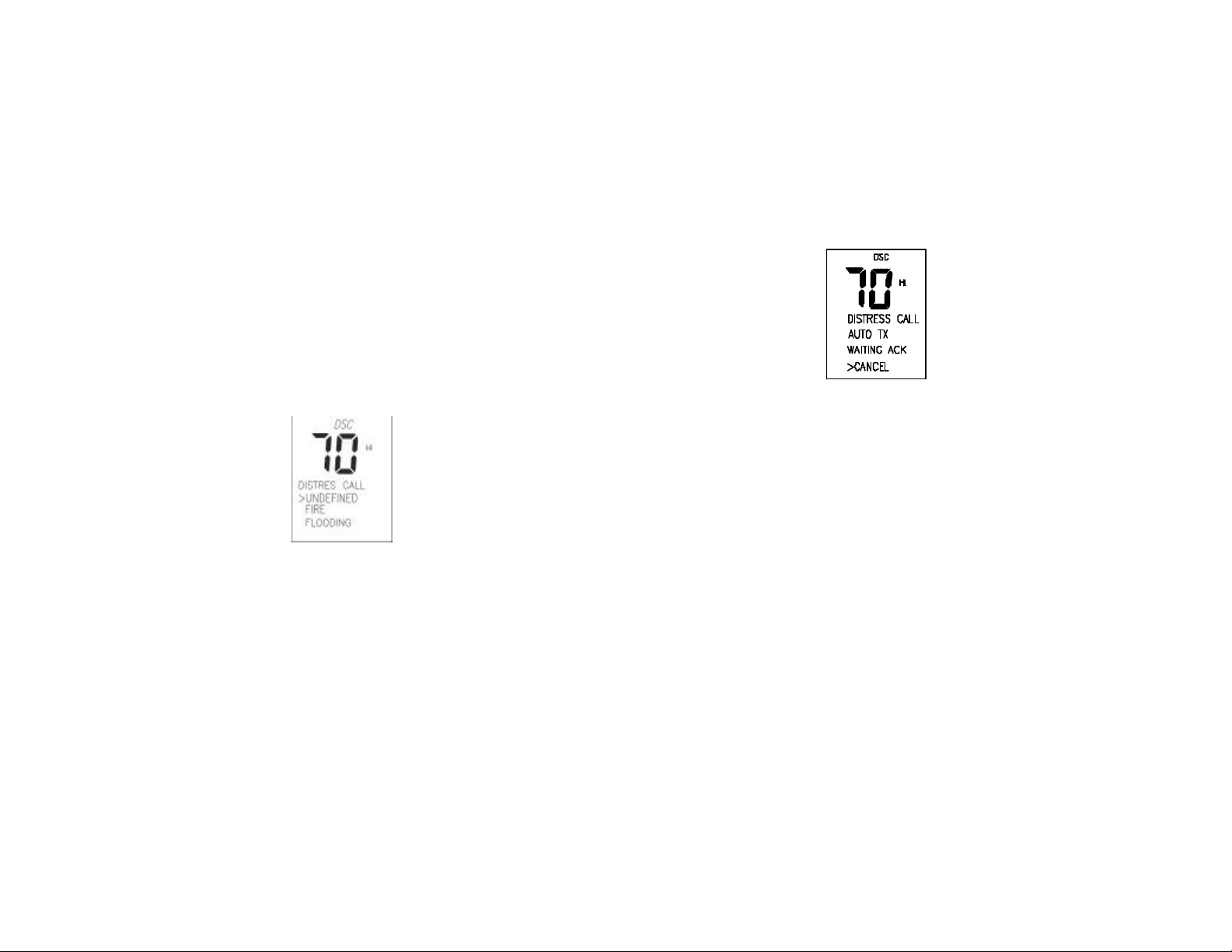
The Text area of the display reconfigures to show the Nature of Distress
menu.
J Note: Only having a MMSI code of your radio, can you initiate a DSC
transmission. To enter the MMSI code, see 6.11.
3. Rotate the Channel/Select knob to select the Nature of Distress by using
“>” arrow.
The default selection is "UNDEFINED".
4. Press the DISTRESS key for more than 4 seconds to send the Distress call.
The acoustic alarms counting second will sound intermittently. The whole
display “flash” in sequence with the “beeps”.
If DISTRESS button is released before 4 seconds, the initiation of distress
call is not activated and you should press 16 key to exit and return to VHF
mode; If DISTRESS button is pressed for more than 4 seconds, DISTRESS
call is sent whether channel 70 is busy or not. When Distress is sent, the
display ceases to flash, the acoustic alarm goes to a continuous tone until
acknowledgement received or press any key is pressed to terminate the
acoustic alarm
During the distress call sequence, the Distress Cancellation menu is present
in the Text Area of the Display. See step 5.3.1.2 to cancel.
During the distress call sequence, the radio simultaneously watches Channel 70
for a DSC Acknowledgement and Channel 16. When the distress call is
acknowledged, the acoustic alarm stops and the display returns to normal VHF
operation on Channel 16, with High power selected. If no acknowledgement is
received, the unit retransmits the DISTRESS call at random intervals of 3.5 to 4.5
minutes whether Channel 70 is busy or not until a response is received or the call
is manually cancelled. By pressing 16 Key button, the radio returns to normal
VHF.
5.3.1.2 Sending a Call to Cancel a Transmitted Distress Call
1. From the Distress Cancellation Menu, cancel the Distress Call by pressing
the Channel/Select key.
The text area of the display reconfigures to have the user confirm the
distress cancellation.
2. Select "YES" and push Channel/Select to transmit a call to cancel the
transmitted distress call. Select "NO" and press Channel/Select button to
abort cancellation.
Once cancellation has been confirmed, the radio returns to normal VHF
operation on channel 16 with high power selected.
5.3.2 ALL SHIPS CALL
Page 21 Page 22
Page 14
5.3.2.1 Send an All Ships Call
All Ships calls are initiated with the f ollowing procedures.
J Note: Pressing the DSC key at any time aborts the current function and selects
the Send Call Main Menu.
1. Press DSC key.
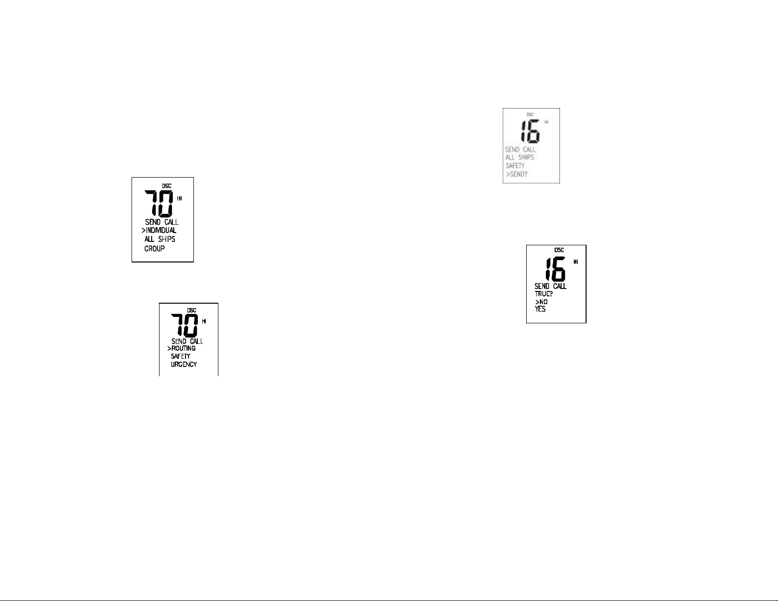
The Send Call Menu appears in the text area of the display.
2. Rotate the Channel/Select knob to select “ALL SHIPS”. Press the
Channel/Select knob to enter.
The Send Call Menu reconfigures to display the Call Type selection menu.
3. Rotate the Channel/Select knob to select the call types, ROUTING,
URGENCY, SAFETY. Push the Channel/Select knob to enter the selected
call type.
If the call type is Urgent or Safety, the talk channel is automatically set to
Channel 16, and the Text Area of the display reconfigures to show the
confirmation screen.
4. Press the Channel/Select knob to confirm the sending; or press 16 key to
quit.
5. rotate the channel/select knob to select “yes”, press the channel/select knob
to send the call
Once the call is sent, the Text area of the display momentarily shows the
Calling All Ships message. The radio returns to normal VHF operation on
the designed channel.
If channel 70 is busy, or an error occurs, after the prescribed number of
automatic broadcast attempts the Text Area of the display reconfigures to
show the Try Again Confirmation menu. See 5.3.2.2.
5.3.3 GROUP CALL
Before sending a GROUP call, you should enter the GROUP MMSI in
set- up mode, for which, please refer to 6.13 GROUP MMSI.
5.3.3.1 Send a GROUP Call
Group call is initiated with the following procedures.
Page 23 Page 24
Page 15
J Note: Pressing the DSC key at any time aborts the current function and selects
the Send Call Main Menu.
1. Press DSC key.
The Send Call Menu appears in the text area of the display.
Rotate the Channel/Select knob to select “GROUP” Press the
Channel/Select knob to enter The Send Call Menu reconfigures to display
the Call Type selection menu.
2. Select “GROUP”. Press the Channel/Select knob to enter. The Send Call
Menu reconfigures to display the select “CH”.
u
3. Rotate the Channel/Select knob to select the take channel Press the
Channel/Select knob to enter. The Send Call Menu reconfigures to display
to appear, the default call type is ROUTING
l
4. Press the Channel/Select knob to send a GROUP CALL, then press ”PTT”
to communicate.
5.3.4.1 Sending an Individual Call ship (MMSI not in Buddy List)
Individual calls are initiated with the following procedure.
J Note: Pressing the DSC key at any time aborts the current function and selects
the Send Call Main Menu.
1. Press DSC key.
The Send Call Menu appears in the text area of the display.
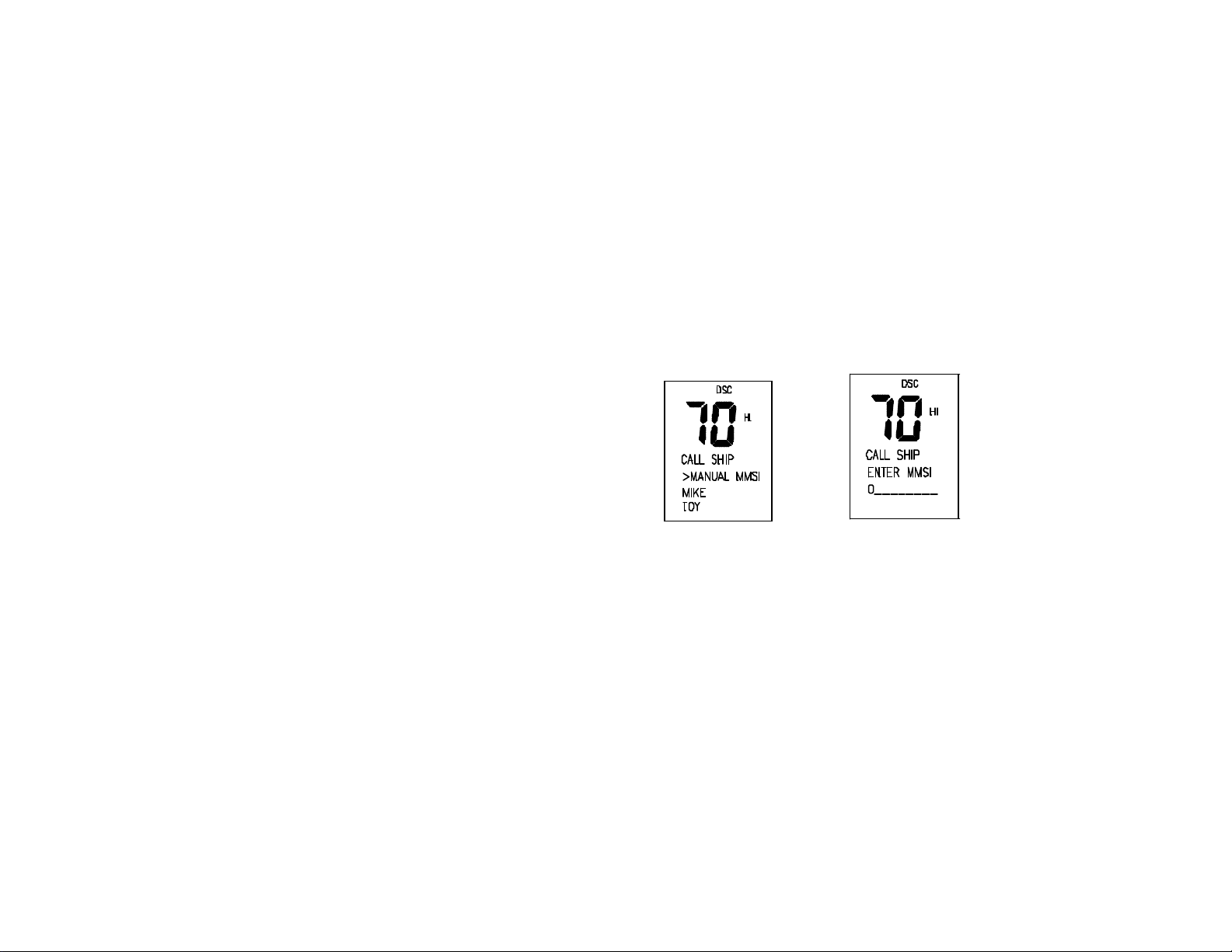
2. Rotate the Channel/Select knob to select “INDIVIDUAL”. Push the
Channel/Select knob to enter.
The Send Call Menu reconfigures to display the call shore call ship selection
menu .rotate the Channel/Select knob to select call ship, push the
Channel/Select knob to select to call ship .the“ MUNUAL MMSI and
“BUDDY LIST ”appears on the screen. select the “MUNUAL MMSI push the
Channel/Select knob to enter the MMSI Enter screen
On the MMSI Enter screen, rotate the Channel/Select knob to change the
individual digits in the MMSI number. Once each digit is set, press
3. the Channel/Select knob to enter the digit and advance to the next. At the
end the MMSI number, the Text Area of the display reconfigures to show
the “select ch “ menu.
The characters available in the digit string are 0-9 and "<" (back arrow).
Selecting the "<" and pushing the Channel/Select knob selects the previous
character in the MMSI for editing.
(Only in the case of a call to a ship, it is permitted to enter a talk channel from a
ific list of intership channels; a call to a coast station, the coast station will
specify the channel to talk on in its acknowledgement.)
4. Rotate the Channel/Select knob to select the talk channel. Push the
Channel/Select knob to enter the channel and proceed to the MMSI Enter
screen. Otherwise, go to step 5.
5. From the Confirmation Screen, push the Channel/Select knob to send the
call.
The Text Area displays the CALLING {MMSI} message while the call is
made.
If the call is acknowledged, the text area momentarily displays the {MMSI}
ACKNOWLEDGED message and the radio tunes the Talk Channel and
returns to normal VHF operation.
If the call is NOT acknowledged, the Try Again Confirmation menu is
displayed. See 5.3.3.1.1.
Page 25 Page 26
Page 16

5.3.4.1. Re-sending an Individual Call
1. From the Try Again Confirmation menu, select "YES" and push the
Channel/Select key to send again. Or, select "NO" and press the
Channel/Select key to cancel and return to normal VHF operation.
5.3.4.2 Sending an Individual Call ship (MMSI stored in Buddy List)
Individual calls to MMSI's in the Buddy List are initiated with the following
procedures. The Buddy List is appended to the Send Call Main Menu. Pressing
the DSC key at any time aborts the current function and selects the Send Call
Main Menu.
1. Press the DSC key.
The Send Call Menu appears in the text area of the display.
Select” individual “item. Push the Channel/Select knob to enter the “call
shore call ship “selection menu
Rotate the Channel/Select knob to select the” call ship” Push the
Channel/Select knob to enter call ship menu
2. Rotate the Channel/Select knob to select the desired name within the
Buddy List. Push the Channel/Select knob to confirm.
The Send Call Menu reconfigures to display the Talk Channel selection
screen. The Call Type is defaulted as ROUTINE.
3. Rotate the Channel/Select knob to select the talk channel. Press the
Channel/Select knob to enter “ call ship” send? menu item
( Only in the case of a call to a ship, it is permitted to enter a talk channel, it is
permitted to enter a talk channel from a ific list of intership channels; a call to a
coast station, the coast station will specify the channel to talk on in its
acknowledgement.)
4 From the Confirmation Screen, push the Channel/Select knob to send
the call.
The Text Area displays the CALLING {Name} message while the call is
made.
If the call is acknowledged, the text area momentarily displays the {Name}
ACKNOWLEDGED message and the radio tunes to the Talk Channel and
returns to normal VHF operation.
If the call is NOT acknowledged, the Try Again Confirmation menu is
displayed. See 5.3.3.2.1.
If the call is acknowledged with unable to comply, the text area will display
“UNABLE TO ACKNOWLEDGED” and pressing Channel/Select key may
enter “re -send.” menu item.
5.3.4.2.1 Re -sending an Individual Call
1. From the Try Again Confirmation menu, select "YES" and push the
Channel/Select key to send again. Or, select "NO" and press the
Channel/Select key to cancel.
5.4 RECEIVING A DSC CALL
When a DSC call is received, the Base Station automatically responds based on
the type of call.
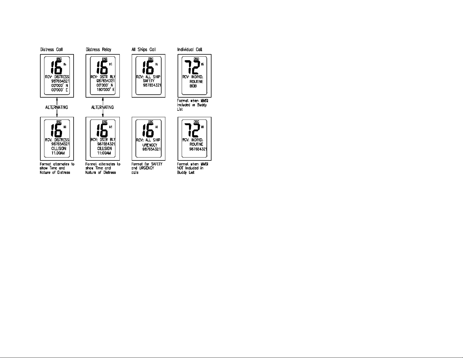
The information displayed on the LCD varies depending upon the call type. See
chart below.
Page 27 Page 28
Page 17
5.4.1 DISTRESS CALL
When a distress call is received, the Base Station automatically tunes to channel
16, and the Distress Alarm Tone sou nds. Pressing any key disables the alarm.
When position data is included within the signal, it is displayed in the Text Area of
the LCD. When no position data is included within the signal, the message "X--, -
- Y--, --" is displayed in the Text Area of the LCD.
5.4.2 DISTRESS RELAY CALL
When a Distress Relay Call is received, the Base Station automatically tunes to
Channel 16, and the Distress Alarm Tone sounds. Pressing any key disables the
alarm.
When position data is included within the signal, it is displayed in the Text Area
of the LCD.
5.4.3 ALL SHIPS CALL
When an All Ships Call is received, the Base Station automatically tunes to the
Channel 16, and the Emergency Alarm Tone Sounds. Press any key to disable
the alarm.
5.4.4 INDIVIDUAL CALL
When an Individual call is received, the Base Station automatically tunes to the
channel designated in the DSC signal, and the Call Alarm Tone Sounds. Press
any key to disable the alarm.
The MMSI contained within the signal is displayed on the Text Area of the
display. If the MMSI correlates to an MMSI stored in the Buddy List, the
corresponding name is displayed in place of the MMSI.
When an Individual call is received, the Base Station always stores the DSC
signal data in the Call Log. And the radio is automatically tuned to the
designated channel.
Page 29 Page 30
Page 18

SET-UP MENU
6.1 DESCRIPTION
A series of set up selections are available in a special mode accessed at start-up.
To enter SET UP operation, press and hold DSC key for greater than 1 second at
any time to abort the current function. The Text area displays the Set- Up Menu
list.
6.1.1 SET-UP MENU NA VIGATION
Items within the Set -Up Menu list are selected by rotating the Channel/Select
knob. To confirm a selected item for adjustment, push the Channel/Select knob.
The display reconfigures allowing the item to be adjusted with Channel/Select
knob. When the desired setting is achieved, press the Channel/Select knob to
enter the setting, and move back to the Main Menu list. Set Up operation is
exited by turning the unit off. All changes are remembered in EEPROM.
During Set-Up operation, no other radio features are available. TX and RX are
disabled.
6.1.2 SET UP FUNCTIONS AND RANGE OF ADJUSTMENT
Items in the SET -UP Menu are as follows and appear in this sequence.
GPS Alarm selects either “ENABLED” or “DISABLED”. When
set to “ENABLED”, the radio alarms when no
navigation data is received; when set to
“DISABLED”, the radio does not alarm even if no
navigation data is received.
Call Log Provides access to calls stored.
Backlight Selects the display backlight setting either HIGH,
LOW or OFF setting. Note the display backlight is
always on, unless set to OFF with this function.
Buddy List Selects the Buddy List Entry routine to enter Names
and MMSI's for frequently called DSC stations.
Position Selects the position setting to enter longitude and
latitude.
UTC Time Selects the UTC time to enter the time.
Contrast Selects display contrast setting: 1- 4 levels.
Key Beep Selects key beep volume, either HIGH or LOW.
Time Offset Selects Time offset to correct UTM to local time.
Setting range is -13 to +13. (New Zealand Daylight
Savings Time requires a 13 hours offset.)
User MMSI Selects the User MMSI Entry routine to enter the
radio's user name and MMSI.
GROUP MMSI Selects the Group MMSI Entry routine to enter the
group’s name and MMSI.
Reset Select options to reset radio to factory settings.
Select “SETTINGS” to return all user settings (Not
User MMSI and Buddy List) to factory settings.
Select Buddy List to Erase individual selections
within the Buddy List.
6.2 GPS ALARM ADJUSTMENT
1. Press and hold the DSC key to display the Set Up menu.
2. Push the Channel/Select knob to display the GPS Alarm Mode Adjustment
menu.
3. Select “ENABLE” and push the Channel/Select knob to enable the GPS
alarm function and return to the Set Up Main Menu Select “DISABLE” and
press the Channel/Select knob to disable the function and return to the Set
Up Main Menu.
Page 31 Page 32
Page 19
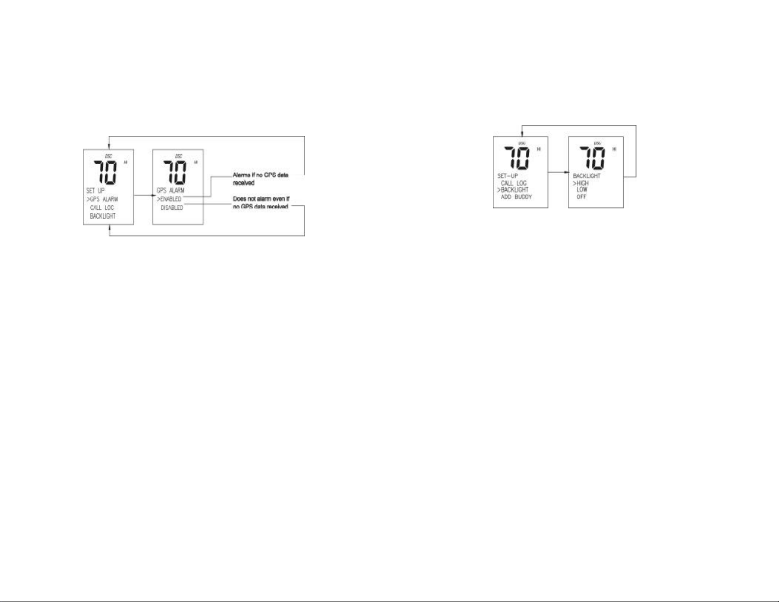
J When the GPS alarm function is enabled, the radio will alarm if no
navigation data is received.
6.3 CALL LOG OPERATION
1. Press and hold the DSC key.
2. Rotate the Channel/Select knob to select “CALL LOG”. Press the
Channel/Select knob to display the Call Log.
3. Distress Call and Individual Call will be logged into CALL LOG. Maximum
amount of logs for “DISTRESS CALL” is ten, while the one for “INDIVIDUAL”
is twenty.
4. The Individual Call log sub- menu provides “CALL BACK” or “DELETE”
selection item, while for Distress Call there is only “DELETE” selection.
6.4 BACKLIGHT ADJUSTMENT
1. Press and hold DSC key.
2. Rotate the Channel/Select knob to select “BACKLIGHT”. Press the
Channel/Select knob to display the Backlight Adjustment menu.
3. Rotate the Channel/Select knob to adjust the setting. Press the
Channel/Select knob to permanently enter the setting and return to the SetUp Menu.
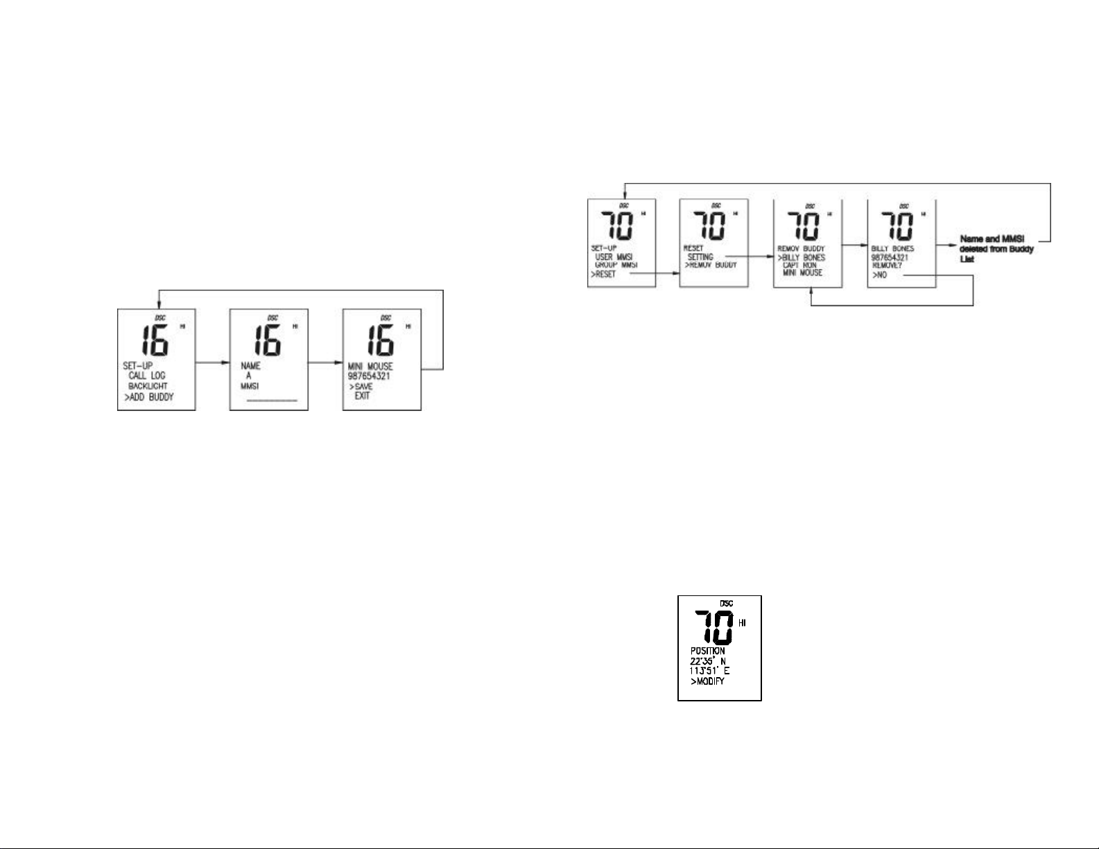
6.5 BUDDY LIST ENTRY
Press and hold DSC key to display the Set Up menu.
Rotate the Channel/Select knob to select Buddy List. Press the Channel/Select
knob to select Buddy List for enter.
The display reconfigures to show the Buddy List entry screen.
Rotate the Channel/Select knob to select the first character (A-Z, 1-9, Space and
Back Arrow "<") for the name. When the desired character is shown, push the
Channel/Select knob to enter, and subsequently activate the next character for
adjustment. Enter each character (up to 12) for the name using this procedure.
When the last digit is entered, the activation advances to the first MMSI digit.
The characters available in the digit string ar e 0-9, A-Z and "<" (back arrow).
Selecting the "<" and pressing the Channel/Select knob selects the previous
character in the MMSI for editing.
If two spaces are entered in sequence, the activation advances to the MMSI
field; or if the last one of the 12 characters is entered, the activation
advances to the MMSI field.
Enter the MMSI using the Channel/Select knob to select and enter the digits (0-
9) for the MMSI. Once the last digit of MMSI is entered, the display advances to
the confirmation menu.
Page 33 Page 34
Page 20
The characters available in the digit string are 0- 9 AND "<" (back arrow).
Selecting the "<" and pushing the Channel/Select knob selects the previous
character in the MMSI for editing.
From the Confirmation Menu, rotate the channel-selecting knob to select “SA VE”
(default selection) and press Channel/Select to permanently save the Name and
MMSI. Select “EXIT” and press Channel/Select knob to discard the information
and return to the Set- Up Main Menu.
6.6 DELETE BUDDY LIST
Follow this procedure to delete entries from the Buddy List.
1. Press and hold DSC key to display the Set Up Main Menu.
2. Rotate the Channel/Select knob to select “RESET”. Press the
Channel/Select knob to enter “RESET” for adjustment.
The display reconfigures to show the Reset Menu entry screen.
1. Rotate the Channel/Select knob to select “BUDDY LIST”. Press the
Channel/Select knob to enter.
The display reconfigures to show the Buddy List.
2. From the Buddy List, rotate Channel/Select knob to select the name to
remove. Press Channel/Select to enter.
The Confirmation Menu appears.
3. From the Confirmation Menu, select “YES” and push Channel/Select to
delete the name and return to the Set-Up Main Menu. Select “NO” to abort
operation and return to the Set- Up Main Menu.
6.7 POSITION
1. Press and hold DSC key to display the Set Up menu.
2. Rotate the Channel/Select knob to select “POSITION”. Press the
Channel/Select knob to display the position menu.
3. Rotate the Channel/Select knob to select the first character (N. S.). When
the desired character is shown, press the Channel/Select knob to enter and
subsequently activate the digit string (0 – 9) and press the Channel/Select
knob to select the digit. When the desire digit is shown, push the
Channel/Select knob to enter.
4. When the last digit of latitude and the longitude is entered, return to the set up menu.
J Note: The function is valid only when your radio are NOT connected to a GPS
receiver.
Page 35 Page 36
Page 21
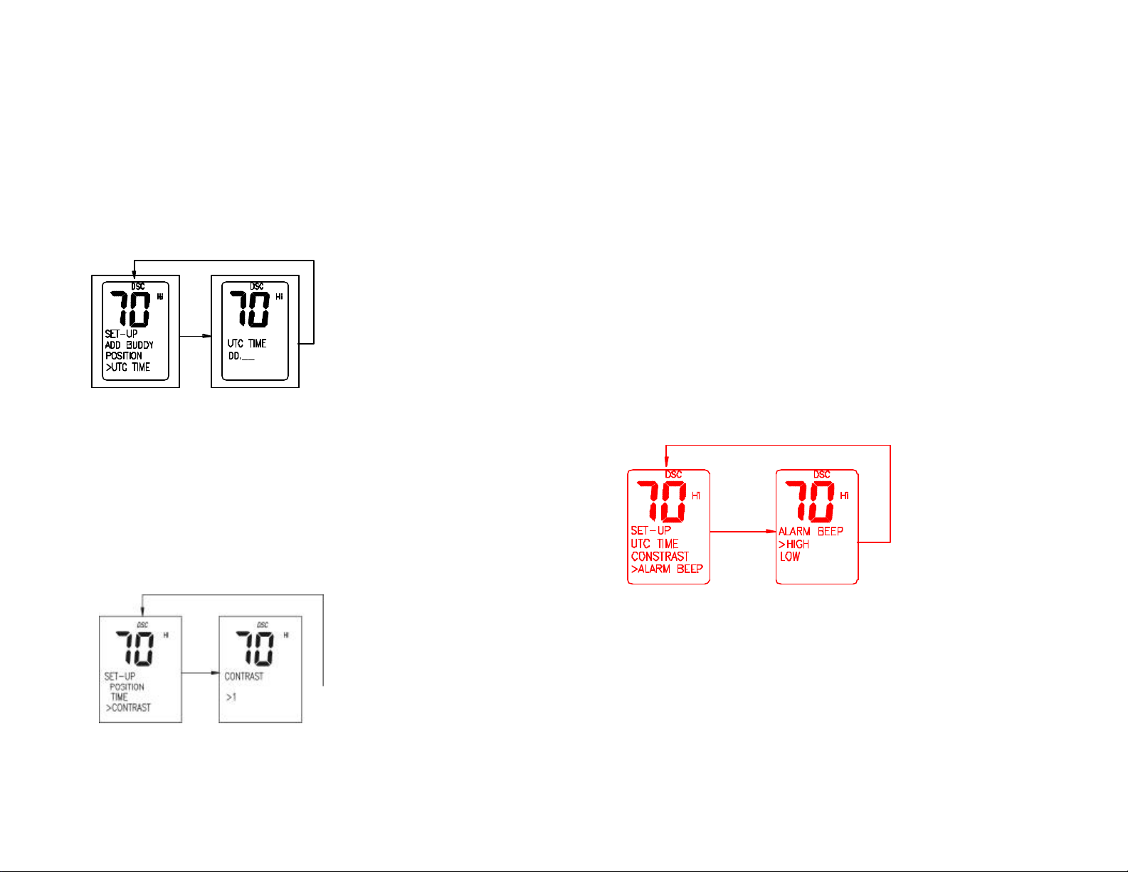
6.8 UTC TIME
1. Press and hold down DSC key to display the Set Up menu.
2. Rotate the Channel/Select knob t o select UTC “TIME”.
3. Push the Channel/Select knob to enter into TIME adjustment, when last
digits are entered, return to the set-up menu.
6.9 CONTRAST ADJUSTMENT
1. Press and hold DSC key to display the Set Up menu.
2. Rotate the Channel/Select knob to select “CONTRAST”.
3. When the display reconfigures, rotate the Channel/Select knob to adjust
the setting. Push the Channel/Select knob to permanently enter the setting
and return to the Set-Up Menu.
6.10 ALARM ADJUSTMENT
1. Press and hold DSC key to display the Set Up menu.
2. Rotate the Channel/Select knob to select “KEY BEEP”. Press the
Channel/Select knob to select Key Beep for adjustment.
3. When the display reconfigures, rotate the Channel/Select knob to adjust the
setting. Push the Channel/Select knob to per manently enter the setting and
return to the Set- Up Menu.
6.11 TIME OFFSET ADJUSTMENT
1. Press and hold DSC key to display the Set Up menu.
2. Rotate the Channel/Select knob to select “TIME OFFSET”.
3. Press the Channel/Select knob to select Time Offset for adjustment. When
Page 37 Page 38
the display reconfigures, rotate the Channel/Select knob to adjust the
setting (-13 to +13 hours). Push the Channel/Select knob to permanently
Page 22
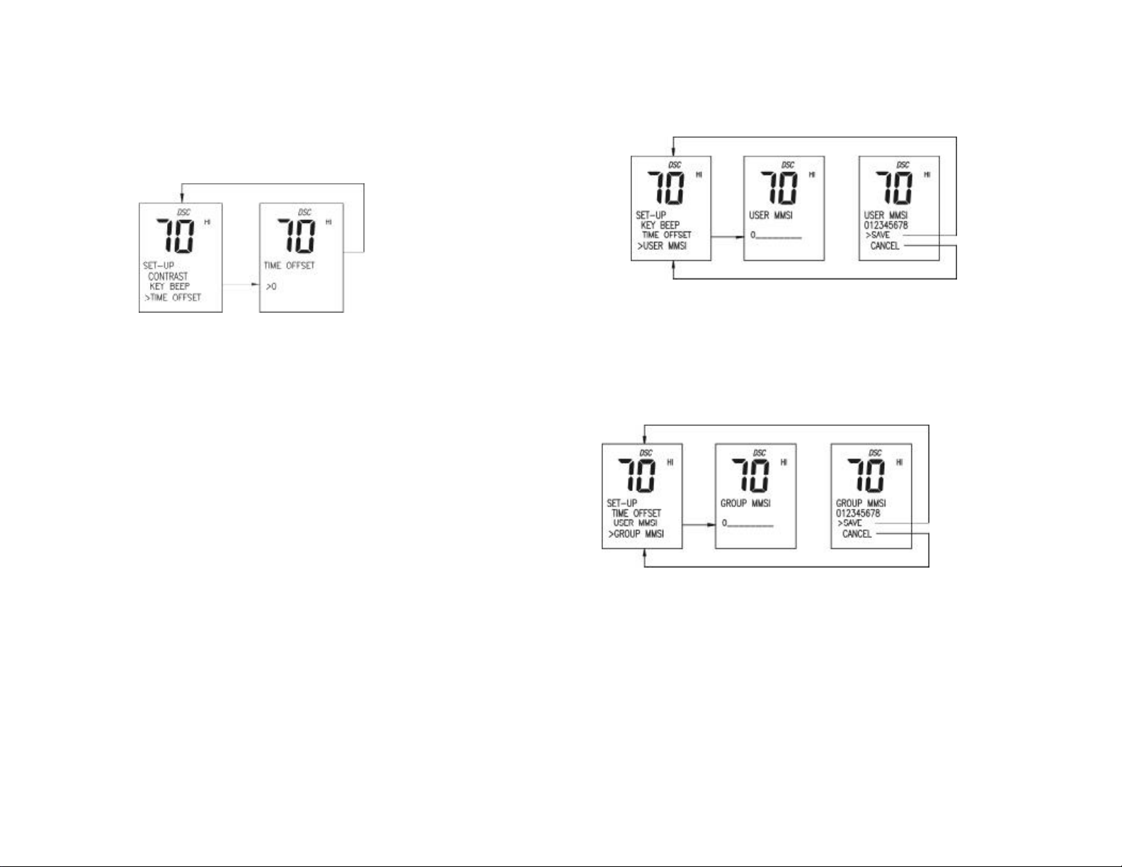
enter the setting and return to the Set-Up Menu.
6.12 USER MMSI ENTRY
1. Press and hold DSC key to display the Set Up menu.
2. Rotate the Channel/Select knob to select “USER MMSI”. Press the
Channel/Select knob to select User MMSI for adjustment.
3. The display reconfigures to show the User MMSI entry screen.
4. Rotate the Channel/Select knob to select the first character (1-9, or Space
or Back Arrow "<") for the MMSI. When the desired digit is shown, press the
Channel/Select knob to enter, and subsequently select the next character
for adjustment. Enter each character for the name using this procedure.
When the last digit is entered, the confirmation screen appears.
5. The characters available in the digit string are 0-9 and "<" (back arrow).
Selecting the "<" and pressing the Channel/Select knob selects the previous
character in the MMSI for editing.
6. From the Confirmation Menu, Rotate the Channel/select knob to select
“SAVE” (default selection) and press Channel/Select to permanently save
the MMSI. Select “CANCEL” and press Channel/Select knob to discard the
information and return to the Set- Up Main Menu.
6.13 GROUP MMSI ENTRY
The procedures are same as that of user’s MMSI entry.
6.14 RESET OPERATION
Follow this procedure to reset User Settings.
1. Press and hold DSC key to display the Set Up Main Menu.
2. Rotate the Channel/Select knob to select “RESET”. Press the
Channel/Select knob to select “RESET” for adjustment.
The display reconfigures to show the Reset Menu Entry screen.
3. Rotate the Channel/Select knob to select “USER SETTINGS”. Press the
Channel/Select knob to enter.
The display reconfigures to show the Confirmation Menu.
Page 39 Page 40
Page 23
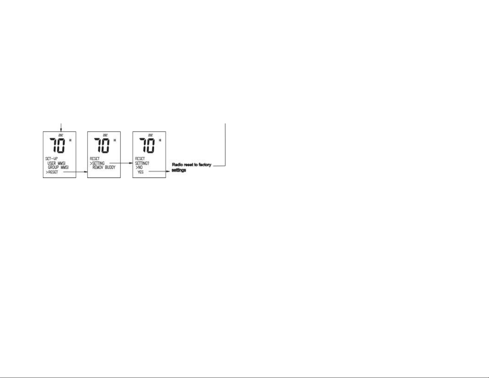
4. From the Confirmation Menu, select “YES” and press Channel/Select to
reset the category, and return to the Set- Up Main Menu. Select “NO” to
abort function and return to the Set- Up Main Menu.
All features are returned to factor y settings, except User MMSI, GROUP
MMSI and Buddy List.
Page 41 Page 42
Page 24
MAINTENANCE
Your VHF Marine Radio *** is a marine radio of water proof who can meet the
requirement of JIS level 7, gives you a good reliability when using in marine
circumstance.
The equipment is designed to be maintenance free. To keep your radio in good
working condition:
l Never unscrew the equipment, either the base station or handset, for in
such case, the water proof performance will be greatly damaged.
l If the radio becomes dirty and dusty, wipe it clean with a moisture cloth, but
pay attention to never using such solvents as benzene or alcohol, for they
may damage the radio surfaces.
l Once your equipment do not work properly, never allow an unqualified
person to tamper with internal adjustments. Please contact the local dealer
for help.
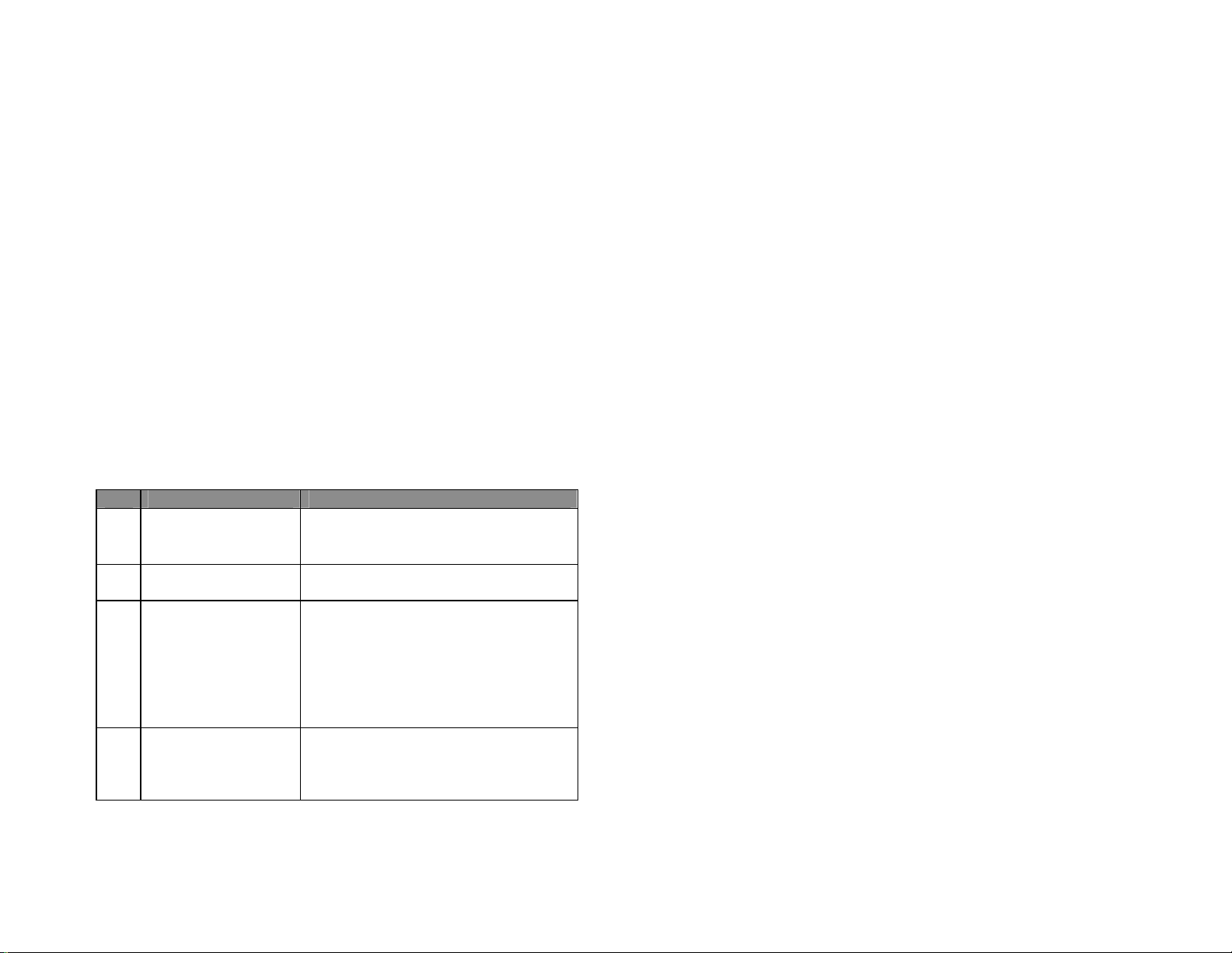
TROUBLE SHOOTING
Item Symptom Cause/Remedy
1 Unit can not be powered
on.
2 No sound comes from
the speaker
3 Transmitting is
impossible, or high
power can not be
selected.
4 Low receiver sensitivity. l Check to see if the antenna being bad
l Check the connection to the base
station.
l Check the volume control.
l Set [VOL] to a suitable level.
l Set squelch to the threshold point.
l Check to see if the PTT switch is
defective.
l Check to see if the microphone or MIC
jack is defective.
l
Some channels are for low power or
receive only, change to another channel.
l Push H/L to select high power.
connected.
l Check the connection between coaxial
cable and base station.
SPECIFICATION
TX Frequency…………………………...……… 156.050 ~ 157.425 MHz
RX Frequency.............………………………….156.025 ~162.025 MHz
Channels........................…………………………..55 USA Channels
55 INT Channels
10 Memory Channels
Modulation type.........................………………………..……………...FM
Antenna impedance...........................………………………...... 50 Ohm
Microphone...............................……………………......condenser type
Power supply....................................…………………………..13.8V DC
Sensitivity at 12dB Sinad.......................................……………..... 0.5µV
Adjacent Channel Rejection................................……………........70dB
Audio output power.............................……………...........2W @ 8 Ohm
Audio Distortion ......... ......................………………………..............10%
RF Output Power....................…………………...High: 23W/Low: 1W
Harmonic Emissions................……………...High: 80dB/Low: 60dB
Dimensions (HWT)..........................................……..... 71×161×147mm
Weight …………………...................................…………………...1290g
Page 43 Page 44
Page 25
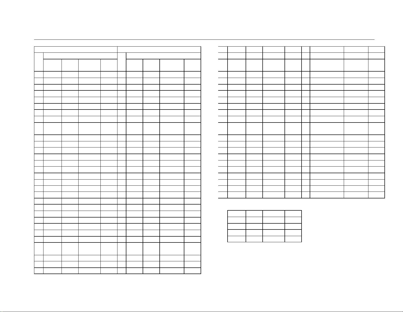
CHANNEL LIST
CH
TX RX Mode Remark
156.050 156.050
01A
02
156.150 156.150
03A
04
156.250 156.250
05A
156.300 156.300
06
156.350 156.350
07A
156.400 156.400
08
156.450 156.450
09
156.500 156.500
10
156.550 156.550
11
156.600 156.600
12
156.650 156.650
13
156.700 156.700
14
…… 156.750
15
156.800 156.800
16
156.850 156.850
17
156.900 156.900
18A
156.950 156.950
19A
157.000 157.000
20A
157.050 157.050
21A
157.100 157.100
22A
157.150 157.150
23A
157.200
24
157.250
25
157.300
26
157.350
27
157.400
28
60
156.075 156.075
61A
62
156.175 156.175
63A
USA INT
Frequency(MHz) Frequency(MHz)
S
S
S
S
S
S
S
S
S
S
S **
S
S
S
S *
S
S
S
S
S
S
161.800
161.850
161.900
161.950
162.000
D
D
D
D
D
S
S
CH
TX RX Mode Remark
156.050 160.650 D
01
156.100 160.700 D
02
156.150 160.750 D
03
156.200 160.800 D
04
156.250 160.850 D
05
156.300 156.300 S
06
156.350 160.950 D
07
156.400 156.400 S
08
156.450 156.450 S
09
156.500 156.500 S
10
156.550 156.550 S
11
156.600 156.600 S
12
156.650 156.650 S
13
156.700 156.700 S
14
156.750 156.750 S *
15
156.800 156.800 S
16
156.850 156.850 S *
17
156.900 161.500 D
18
156.950 161.550 D
19
157.000 161.600 D
20
157.050 161.650 D
21
157.100 161.700 D
22
157.150 161.750 D
23
157.200
24
157.250
25
157.300
26
157.350
27
157.400
28
156.025 160.625 D
60
156.075 160.675 D
61
156.125 160.725 D
62
156.175 160.775 D
63
161.800 D
161.850 D
161.900 D
161.950 D
162.000 D
156.225 156.225
64A
156.275 156.275
65A
156.325 156.325
66A
156.375 156.375
67
156.425 156.425
68
156.475 156.475
69
156.525 156.525
70
156.575 156.575
71
156.625 156.625
72
156.675 156.675
73
156.725 156.725
74
156.875 156.875
77
156.925 156.925
78A
156.975 156.975
79A
157.025 157.025
80A
157.075 157.075
81A
157.125 157.125
82A
157.175 157.175
83A
157.225
84
157.275
85
157.325
86
157.375
87
157.425 157.425
88A
*=1Watt
WX0
WX1
WX2
WX3
WX4
161.825
161.875
161.925
161.975
163.275
162.550
162.400
162.475
162.425
Notes: Simplex channel 3, 21, 23, 61, 64, 81, 82 and 83, are not for use
by the general public in the U.S. waters.
S
S
S
S **
S
S
S
S
S
S
S
S
S
S
S
S
S
S
D
D
D
D
S
51/9D/42S
WX5
WX6
WX7
WX8
WX9 161.775
162.450
162.500
162.525
161.650
156.225 160.825 D
64
156.275 160.875 D
65
156.325 160.925 D
66
156.375 156.375 S
67
156.425 156.425 S
68
156.475 156.475 S
69
156.525 156.525 S
70
156.575 156.575 S
71
156.625 156.625 S
72
156.675 156.675 S
73
156.725 156.725 S
74
156.875 156.875 S
77
156.925 161.525 D
78
156.975 161.575 D
79
157.025 161.625 D
80
157.075 161.675 D
81
157.125 161.725 D
82
157.175 161.775 D
83
157.225
84
157.275
85
157.325
86
157.375
87
157.425 162.025 D
88
161.825 D
161.875 D
161.925 D
161.975
D
55/35D/20S
Page 45 Page 46
 Loading...