

Page 1
MID-TECH
MIDWEST TECHNOLOGIES, INC.
TASC-6000, 6300, & 6600
Total Application Sprayer Control System
User Guide
PN - 98-05010
Rev. # - 1
CE & STANDARD VERSION
Flow
RATE
CHEMICAL APPLICATORS
123
.
Gal./
4 5 6
-Ac
MIDWEST TECHNOLOGIES, INC.
Alt.Rate
ON
OFF
MID-TECH
TASC-6600
TOTAL APPLICATION
SPRAYER CONTROL
®
ON OPERATE INC.
OFF SET- UP
CHEMICALS
Chem. Rate Appl. Rate
Chem. Applied
Area
Speed
123456789
BOOMS
%Rate
Scan
Test
Speed
DISPLAY SELECTOR
Total Applied
Distance
Prime
DEC.
CARRIER
Width
Midwest Technologies, Inc. of Illinois
2733 East Ash St. - Springfield, IL 62703
Phone 217-753-8424 - Fax 217-753-8426
www.mid-tech.com
Page 2

TASC MANUAL - CHANGE LOG
DATE: Revision PAGES AFFECTED: SW Version:
5/26/00 1 New Manual. 3.21
II
Page 3

TASC-6000, 6300, 6600
98-05010
Rev. - 1
TABLE OF CONTENTS
TASC MANUAL - CHANGE LOG ....................................................................................................................................... II
TABLE OF CONTENTS ....................................................................................................................................................... III
1.0 SWITCHES AND CONTROLS ..................................................................................................................................... 1-1
1.1 POWER SWITCH .................................................................................................................................................. 1-1
1.2 MODE SELECTOR OPERATE/SET- UP SWITCH ................................................................................................. 1-1
1.3 INC/DEC SWITCH ................................................................................................................................................. 1-1
1.4 DISPLAY SELECTOR ............................................................................................................................................ 1-1
1.4.1 DISPLAY SELECTOR FUNCTIONS IN OPERATE MODE .......................................................................... 1-2
1.4.2 DISPLAY SELECTOR FUNCTIONS IN SET UP MODE .............................................................................. 1-3
1.5 BOOM SECTION “ON/OFF” INDICATORS ........................................................................................................ 1-4
1.6 INJECTION PUMP SWITCHES (TASC 6300 and 6600 only) ............................................................................... 1-4
1.7 STATUS SWITCH ................................................................................................................................................. 1-4
1.8 GROUND SPEED OVERRIDE SWITCH ................................................................................................................ 1-5
2.0 CALIBRATION AND SET UP ...................................................................................................................................... 2-1
2.1 ENGLISH AND METRIC UNITS ...........................................................................................................................2-1
2.1.1 UNITS FOR EACH POSITION .................................................................................................................... 2-1
2.1.2 CHANGING UNITS ..................................................................................................................................... 2-1
2.2 PERISTALTIC AND NON-PERISTALTIC INJECTION PUMP MODES ................................................................2-1
2.3 SETTING APPLICATION RATES ......................................................................................................................... 2-2
2.3.1 SETTING CARRIER APPLICATION RATE ................................................................................................. 2-2
2.3.2 SETTING CHEMICAL APPLICATION RATE ............................................................................................. 2-2
2.3.3 SETTING ALTERNATE CHEMICAL APPLICATION RATE ...................................................................... 2-3
2.4 SETTING THE % RATE CHANGE OF THE CHEMICAL INJECTION PUMPS & THE CARRIER ........................ 2-3
2.5 SETTING BOOM WIDTHS ................................................................................................................................... 2-4
2.6 FLOW METER CALIBRATION ............................................................................................................................ 2-4
2.6.1 TYPICAL FLOWMETER CALIBRATION NUMBERS (for water) .............................................................. 2-5
2.6.2 FLOW METER CALIBRATION PROCEDURE ............................................................................................2-5
2.7 DISTANCE CALIBRATION, GROUND SPEED SENSOR ......................................................................................2-6
2.7.1 GENERAL CONSIDERATIONS AND INITIAL CALIBRATION NUMBERS .............................................. 2-6
2.7.2 DISTANCE CALIBRATION PROCEDURE .................................................................................................. 2-7
2.8 INJECTION PUMP CALIBRATION (TASC-6300 & 6600 ONLY) .......................................................................... 2-7
2.8.1 TYPICAL PUMP CALIBRATION NUMBERS, PC# .................................................................................... 2-8
2.8.2 PUMP CALIBRATION, FIELD PROCEDURE .............................................................................................. 2-8
2.8.3 ESTABLISHING THE “PRIME” VOLUME FOR EACH INJECTION PUMP .............................................. 2-10
2.9 SETTING THE "HOLD/CLOSE" RESPONSE OF THE FLOW CONTROL VALVE ............................................... 2-12
2.9.1 STATUS SWITCH ..................................................................................................................................... 2-12
2.9.2 ALL BOOMS "OFF" ................................................................................................................................. . 2-13
2.10 SETTING THE GROUND SPEED OVERRIDE "GSO" VALUE. ........................................................................... 2-13
2.11. SETTING AUTO POWER DOWN TIME ........................................................................................................... 2-14
2.12 REFLOW MODE ............................................................................................................................................... 2-14
2.12.1. DESCRIPTION ........................................................................................................................................ 2-14
2.12.2. REFLOW SET UP ................................................................................................................................... 2-15
2.12.3. ESTABLISHING THE REFLOW OPTION ............................................................................................... 2-15
2.12.4. CANCELLING THE REFLOW OPTION .................................................................................................. 2-15
2.12 OPERATING UNDER EXTERNAL RATE COMMANDS .................................................................................. 2-16
III
Page 4

98-05010
TASC-6000, 6300, 6600
Rev. - 1
3.0. OPERATION ................................................................................................................................................................3-1
3.1. NORMAL START UP AND OPERATION ............................................................................................................ 3-1
3.2. CHANGING ACTIVE BOOM SECTIONS .............................................................................................................3-1
3.3. SELECTING DIFFERENT CHEMICAL COMBINATIONS ................................................................................... 3-1
3.4. CHANGING THE APPLICATION RATE “ON THE GO” ...................................................................................... 3-2
3.4.1. CHANGING APPLICATION RATE OF THE MAIN CARRIER .................................................................. 3-2
3.4.2. CHANGING APPLICATION RATE OF THE INJECTED CHEMICALS (TASC 6300/6600 ONLY) .............. 3-2
3.4.2.1. CHANGING ALL INJECTION RATES SIMULTANEOUSLY ............................................................3-2
3.4.2.2. ALTERNATE RATES FOR INDIVIDUAL CHEMICALS .................................................................. 3-3
3.5. PRIMING THE INJECTION LINES (TASC 6300/6600 ONLY) ............................................................................... 3-3
3.6. GROUND SPEED OVERRIDE ............................................................................................................................... 3-4
3.7. PRIMING THE MAIN PUMP AND BOOM .......................................................................................................... 3-4
3.8. MANUAL OVERRIDE OF FLOW CONTROL VALVE ..........................................................................................3-5
4.0. MAINTENANCE .........................................................................................................................................................4-1
4.1. FLUSHING AND CLEANING ...............................................................................................................................4-1
4.2. INJECTION PUMPS ............................................................................................................................................. 4-1
4.2.1. WEEKLY PUMP MAINTENANCE ............................................................................................................. 4-1
4.2.2. SEASONAL PUMP MAINTENANCE ........................................................................................................ 4-2
4.2.3. PERIODIC PUMP MAINTENANCE ........................................................................................................... 4-2
4.3. CONTROL CONSOLE ........................................................................................................................................... 4-2
4.4. GROUND SPEED SENSOR ................................................................................................................................... 4-2
4.5. FLOWMETER ...................................................................................................................................................... 4-2
4.6. FLOW CONTROL VALVE ..................................................................................................................................... 4-3
4.7. WIRING HARNESS .............................................................................................................................................. 4-3
5.0 TASC ERROR MESSAGES, COMMON CONDITIONS AND SOLUTIONS ................................................................. 5-1
6.0. EMERGENCY OPERATIONS ....................................................................................................................................... 6-1
6.1. GROUND SPEED SENSOR FAILURE ...................................................................................................................6-1
6.2. FLOW CONTROL VALVE FAILURE .................................................................................................................... 6-2
6.3. FLOWMETER FAILURE ...................................................................................................................................... 6-2
A.0 SYSTEM DRAWINGS ................................................................................................................................................A-1
A.1 TASC 6300 SYSTEM WIRING DIAGRAM ......................................................................................................... A-2
A.2 TASC 6600 SYSTEM PLUMBING DIAGRAM ....................................................................................................A-3
A.3 REFLOW PLUMBING DIAGRAM ...................................................................................................................... A-4
A.4 FLUID OUNCES CONVERSION TABLE ............................................................................................................. A-5
A.5 TUBE SELECTION CHART .................................................................................................................................A-6
B.0. SYSTEM OVERVIEW ................................................................................................................................................. B-2
B.1. THE TASC SYSTEM CONTROLS BOTH CARRIER FLOW AND CHEMICAL INJECTION RATES .................. B-2
B.1.1. HOW A TASC-6000, 6300 or 6600 CONTROLS CARRIER APPLICATION RATE .................................... B-2
B.1.2. HOW A TASC-6300 AND 6600 CONTROLS CHEMICAL APPLICATION RATE .................................... B-3
B.2. TASC SYSTEM COMPONENT PARTS .............................................................................................................. B-4
B.2.1. THE TASC CONTROL CONSOLE ............................................................................................................ B-4
B.2.2. FLOWMETER ........................................................................................................................................... B-4
B.2.3. FLOW CONTROL VALVE ......................................................................................................................... B-5
B.2.4. GROUND SPEED SENSOR ........................................................................................................................ B-5
B.2.5. BOOM INTERFACE .................................................................................................................................. B-5
B.2.6. PRECISION INJECTION PUMPS .............................................................................................................. B-5
B.2.7. CHEMICAL CONTAINERS ...................................................................................................................... B-6
IV
Page 5

TASC-6000, 6300, 6600
98-05010
Rev. - 1
C.0. INSTALLATION ........................................................................................................................................................ C-2
C.1. CONTROL CONSOLE INSTALLATION ............................................................................................................. C-2
C.1.1. CONSOLE MOUNTING ............................................................................................................................ C-2
C.1.2. CONSOLE CABLE ROUTING ................................................................................................................... C-3
C.2. FLOWMETER INSTALLATION ......................................................................................................................... C-4
C.3. FLOW CONTROL VALVE INSTALLATION ....................................................................................................... C-5
C.4. GROUND SPEED SENSOR INSTALLATION ...................................................................................................... C-5
C.5. BOOM CONTROL SWITCHES AND INTERFACE ............................................................................................ C-5
C.5.1. BOOM CONTROL SWITCH BOX ............................................................................................................ C-5
C.5.2. BOOM INTERFACE CABLE . .................................................................................................................... C-6
C.6. INJECTION PUMP INSTALLATION ................................................................................................................. C-6
C.6.1. SELECTING THE CORRECT PUMP FOR THE APPLICATION ................................................................ C-6
C.6.2. INJECTION PUMP LOCATION ................................................................................................................ C-7
C.6.3. CLEARANCE AND MOUNTING OF INJECTION PUMPS ...................................................................... C-7
C.6.4. INJECTION PUMP CABLE ROUTING ...................................................................................................... C-7
C.6.5. PRECISION PERISTALTIC INJECTION PUMP TUBING INSTALLATION .............................................. C-8
C.7. CHEMICAL CONTAINERS ................................................................................................................................ C-9
C.7.1. MOUNTING AND PLUMBING MID-TECH TANKS ................................................................................ C-9
C.7.2. GENERAL SUGGESTIONS FOR PLUMBING CHEMICAL TANKS ....................................................... C-10
D.0. TASC ROADSIDE/HANDGUN OPERATION ............................................................................................................ D-2
D.1 Modes of Operation ............................................................................................................................................. D-2
D.1.1 Normal ........................................................................................................................................................ D-2
D.1.2 Handgun ..................................................................................................................................................... D-2
D.2. HANDGUN MODE OPERATION ....................................................................................................................... D-3
D.2.1. HANDGUN MODE, SET-UP FUNCTIONS ............................................................................................... D-3
D.2.2. HANDGUN MODE, OPERATE FUNCTIONS .......................................................................................... D-3
D.2.3. HANDGUN MODE, SPECIAL CONSIDERATIONS: . ...............................................................................D-4
D.2.4. HANDGUN MODE, TYPICAL OPERATION: ...........................................................................................D-4
D.2.5. HANDGUN MODE, MANUAL VALVE OVERRIDE: ................................................................................ D-5
D.2.6. HANDGUN MODE, ERROR MESSAGES ................................................................................................. D-5
D.2.7. HANDGUN MODE, PRINTER OUTPUT SAMPLES ................................................................................ D-6
D.3. NORMAL MODE OPERATION ......................................................................................................................... D-6
D.3.1. NORMAL MODE, AUTOMATIC "PRESSURE" OPERATION ................................................................ D-6
D.3.2. NORMAL MODE, SPECIAL PURPOSE BOOM WIDTHS ....................................................................... D-7
D4 - ROADSIDE SYSTEM DIAGRAM ....................................................................................................................... D-8
D5 - ROADSIDE SYSTEM DIAGRAM W/MID-TECH SWITCHBOX ....................................................................... D-9
V
Page 6

98-05010
Rev. - 1
TASC-6000, 6300, 6600
This page purposely left blank
VI
Page 7
TASC-6000, 6300, 6600
1.0 SWITCHES AND CONTROLS
98-05010
Rev. - 1
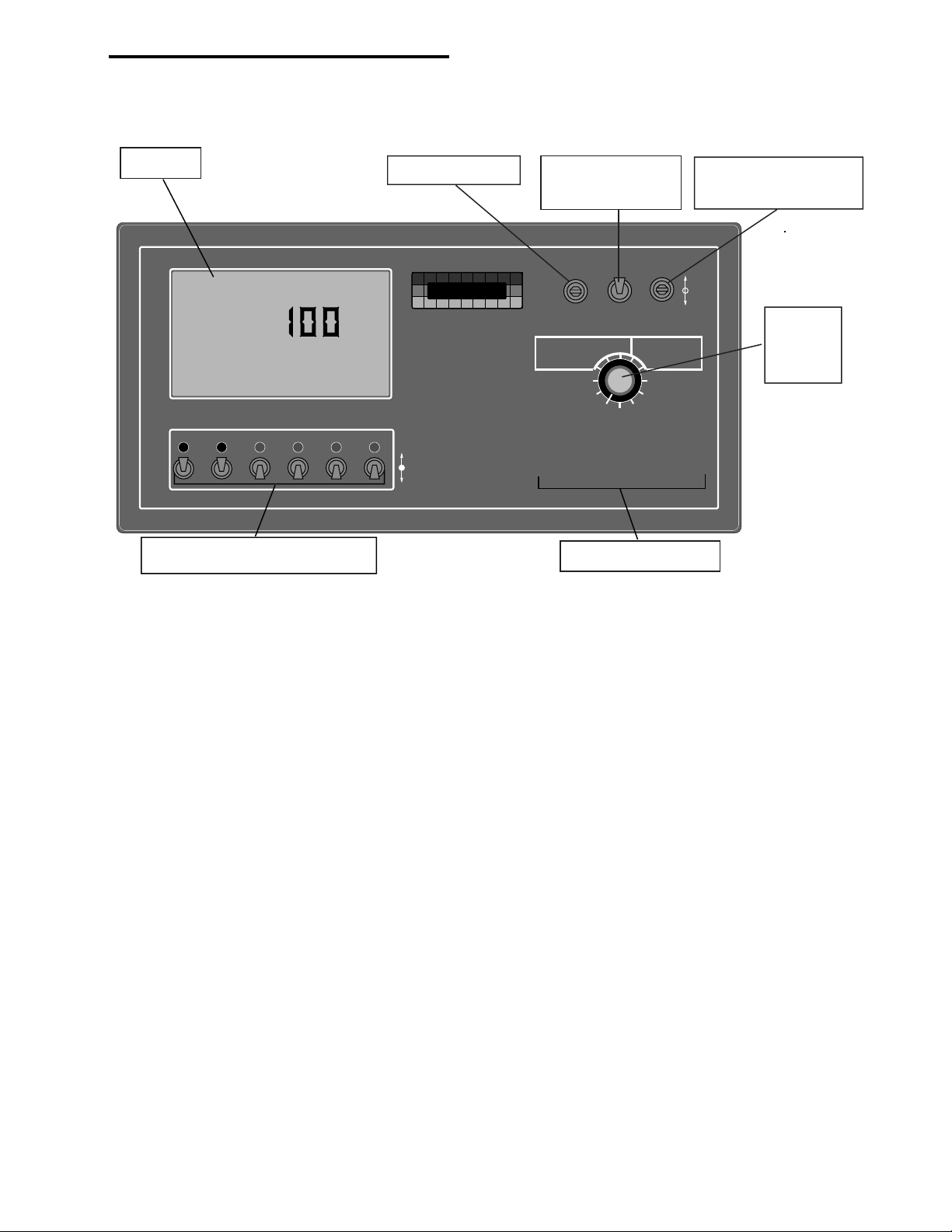
Display
Flow
RATE
Gal./
CHEMICAL APPLICATORS
123
4 5 6
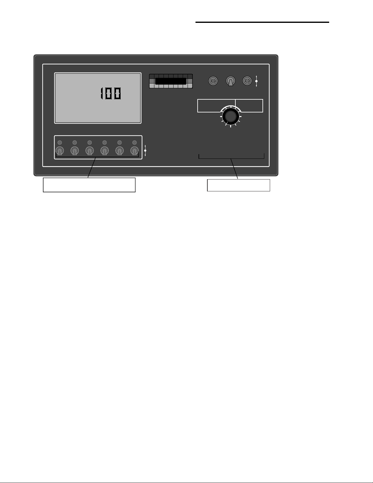
Injection Pump Switches
Power Switch
-Ac
.
MID-TECH
MIDWEST TECHNOLOGIES, INC.
TASC-6600
TOTAL APPLICATION
SPRAYER CONTROL
Alt.Rate
ON
OFF
Mode Selector
Switch
ON OPERATE INC.
®
OFF SET- UP
CHEMICALS
Chem. Rate Appl. Rate
Chem. Applied
Area
Speed
Scan
DISPLAY SELECTOR
1234567 89
BOOMS
%Rate
Test
Speed
DEC.
Total Applied
Width
Distance
Prime
CARRIER
Increase/Decrease
switch
Display
Selector
Switch
Boom Indicators
1.1 POWER SWITCH
The power switch controls power to the console. The console has an "Auto Power Down" feature which powers the
console off after an operator selectable time (default is 30 min) has elapsed. The console has a nonvolatile memory so it
"remembers" the constants and data previously entered, even if the power is removed.
NOTE: The “Auto Power Down Feature is only available on the CE version of the console (CE designation label on back
of console).
1.2 MODE SELECTOR OPERATE/SET- UP SWITCH
The Mode Selector switch (upper right) is used to switch between the OPERATE and SET-UP modes. When spraying,
this switch must be in the OPERATE position. The SET- UP position is used for entering information into the console.
In the SET-UP Mode, all pump operations (except calibration) are turned off and an Err message appears if a position
which can not be programmed is selected.
1.3 INC/DEC SWITCH
The INC/DEC switch (upper right) is used to adjust the values appearing in the display. The INC/DEC switch is used in
both OPERATE and SET-UP Modes.
This switch is also used to zero the accumulated areas, distance, and volumes by selecting the desired display and
holding this switch in the DEC position until the display resets to zero, (approximately 3 sec).
1.4 DISPLAY SELECTOR
The Display Selector (right center) is used to select the various console functions that are to be displayed and adjusted.
1-1
Page 8

98-05010
MID-TECH
MIDWEST TECHNOLOGIES, INC.
ON
OFF
Alt.-
Rate
TASC-6600
TOTAL APPLICATION
SPRAYER CONTROL
1234567 89
BOOMS
6
Ac
®
OFF SET- UP
DEC.
ON OPERATE INC.
%Rate
DISPLAY SELECTOR
Speed
Area
Width
Distance
Chem. Applied
Test
Speed
Prime
Total Applied
Chem. Rate Appl. Rate
CHEMICALS
CARRIER
Scan
MID-TECH
Ac
®
OFF SET- UP
DEC.
ON OPERATE INC.
MID-TECH
®
OFF SET- UP
DEC.
ON OPERATE INC.
Rev. - 1
1.4.1 DISPLAY SELECTOR FUNCTIONS IN OPERATE MODE
(Refer to Appendix D for these switch functions in "Handgun Mode".)
ON OPERATE INC.
OFF SET- UP DEC.
TASC-6000, 6300, 6600
Flow
RATE
CHEMICAL APPLICATORS
123
.
Gal./
CHEMICALS
Chem. Rate Appl. Rate
Chem. Applied
Area
4 5 6
Speed
Scan
DISPLAY SELECTOR
-Ac
MIDWEST TECHNOLOGIES, INC.
%Rate
Alt.-
Total Applied
Rate
ON
OFF
Distance
Prime
Test
Speed
MID-TECH
TASC-6600
TOTAL APPLICATION
SPRAYER CONTROL
CARRIER
Width
ON OPERATE INC.
®
OFF SET- UP
DEC.
CHEMICALS
%Rate
Chem. Rate Appl. Rate
Chem. Applied
1234567 89
BOOMS
Area
Speed
Scan
DISPLAY SELECTOR
Total Applied
Width
Distance
Prime
Test
Speed
CARRIER
SPEED: The current vehicle speed.
AREA: Accumulated Area #1.*
CHEMICALS CHEM. APPLIED: The amount of chemical actually pumped by each injection pump. The display
cycles through each pump in sequence unless a specific pump switch is selected ON.*
CHEMICALS CHEM. RATE: The programmed application rate to be delivered by each injection pump. The display
cycles through each pump in sequence unless a specific pump switch is selected ON. An alternate rate can also be
programmed for each pump. In order to view the Alternate rate, the individual pump switch must be set to the ALT.
RATE position.
CHEMICALS % RATE: The percent of target application rate at which all active injection pumps are operating. This
percentage can be changed up or down a preset amount by operating the INC/DEC switch.***
CARRIER APPL. RATE: The target application rate of the main carrier (including chemical). Once spraying opera-
tions have started, and main carrier flow is established, the actual measured flow rate of the sprayer will be displayed
here.***
CARRIER TOTAL APPLIED: The actual volume of carrier, including chemical applied, as measured by the flow
meter.*
WIDTH: The active boom width. Depends on the actual boom sections selected ON and the individual widths pro-
gramed into each section.
DISTANCE: The accumulated distance.*
PRIME: This position is used during priming operations to fill the injector pump lines with chemical or to lock the
control valve open during main pump priming.
TEST SPEED: The speed the console uses for stationary tests of the sprayer.**
SCAN: The display scans SPEED, AREA, CHEMICALS-CHEM. APPLIED by active pumps, CHEMICALS-
CHEM. RATE of active pumps, CARRIER-APPL. RATE and CARRIER-VOLUME APPLIED. The display
holds at each position for approximately two seconds.
NOTES: * Totals can be zeroed in this mode.
** Values are programmable in this mode.
*** Values changeable by a % increase or decrease.
1-2
Page 9

TASC-6000, 6300, 6600
MID-TECH
MIDWEST TECHNOLOGIES, INC.
ON
OFF
Alt.-
Rate
TASC-6600
TOTAL APPLICATION
SPRAYER CONTROL
1234567 89
BOOMS
6
Ac
®
OFF SET- UP
DEC.
ON OPERATE INC.
%Rate
DISPLAY SELECTOR
Speed
Area
Width
Distance
Chem. Applied
Test
Speed
Prime
Total Applied
Chem. Rate Appl. Rate
CHEMICALS
CARRIER
Scan
MID-TECH
Ac
®
OFF SET- UP
DEC.
ON OPERATE INC.
MID-TECH
®
OFF SET- UP
DEC.
ON OPERATE INC.
1.4.2 DISPLAY SELECTOR FUNCTIONS IN SET UP MODE
(Refer to Appendix D for these switch functions in "Handgun Mode".)
ON OPERATE INC.
OFF SET- UP DEC.
98-05010
Rev. - 1
Flow
RATE
CHEMICALS
CHEMICAL APPLICATORS
123
-Ac
.
Gal./
%Rate
Chem. Rate Appl. Rate
Chem. Applied
Area
4 5 6
Speed
Scan
DISPLAY SELECTOR
MIDWEST TECHNOLOGIES, INC.
TASC-6600
TOTAL APPLICATION
SPRAYER CONTROL
Alt.-
Total Applied
Rate
ON
Width
OFF
Distance
Prime
Test
Speed
MID-TECH
CARRIER
ON OPERATE INC.
®
OFF SET- UP
DEC.
CHEMICALS
%Rate
Chem. Rate Appl. Rate
Chem. Applied
1234567 89
BOOMS
Area
Speed
Scan
DISPLAY SELECTOR
Total Applied
Width
Distance
Prime
Test
Speed
CARRIER
SPEED: Ground Speed Override (GSO) Value
AREA: Accumulated Area #2.*
CHEMICALS CHEM. APPLIED: Injection pump calibration number for the pump that is turned ON. Err means no
pump is selected or more than one pump is selected.**
CHEMICALS CHEM. RATE: The volume per acre to be delivered by an individual injection pump. Each pump must
be selected ON in sequence. Two rates are programmable, one in each position of the injection pump switch: ON -
Standard Rate or Alt. Rate - Alternate Rate. Err means no pump is selected or more than one pump is selected.**
CHEMICALS % RATE: The percent of change applied to all active injection pump application rates for each actuation
of the INC/DEC switch.**
CARRIER APPL. RATE: The target application rate of the main carrier, including injected chemical.**
CARRIER TOTAL APPLIED: The flow meter calibration number**
WIDTH: Individual boom section widths. The display cycles through the individual boom sections sequentially, unless
a particular boom switch is activated.**
DISTANCE: The current distance calibration number.**
PRIME: The prime volumes for the pump that is turned ON. Err means no pump is selected or more than one pump is
selected.**
TEST SPEED: The speed the console uses for stationary tests of the sprayer.**
SCAN: Err: This is an invalid switch combination.
NOTES: * Totals can be zeroed in this mode.
** Values are programmable in this mode.
*** Values changeable by a % increase or decrease.
1-3
Page 10
98-05010
Rev. - 1
1.5 BOOM SECTION “ON/OFF” INDICATORS
TASC-6000, 6300, 6600
Flow
RATE
.
Gal./
CHEMICAL APPLICATORS
123
4 5 6
Injection Pump Switches
-Ac
MIDWEST TECHNOLOGIES, INC.
TASC-6600
TOTAL APPLICATION
SPRAYER CONTROL
Alt.Rate
ON
OFF
MID-TECH
ON OPERATE INC.
®
OFF SET- UP
CHEMICALS
Chem. Rate Appl. Rate
Chem. Applied
Area
Speed
Scan
DISPLAY SELECTOR
1234567 89
BOOMS
%Rate
Test
Speed
DEC.
Total Applied
Width
Distance
Prime
CARRIER
Boom Indicators
The boom section on/off indicators (lower right, labeled BOOMS), indicate which boom sections are active (turned on).
There is a maximum of nine boom section positions available.
1.6 INJECTION PUMP SWITCHES (TASC 6300 and 6600 only)
(Refer to Appendix D for these switch functions in "Handgun Mode".)
The injection pump switches (lower left) are used to activate the injection pumps. Up to six separate injection pumps can
be controlled by the TASC console. Each pump has its own product switch and indicator light. When the switch is in the
down position, the injection pump is OFF. When the switch is in the ON position, the pump is pumping at the standard
target rate, (the pump indicator light glows steadily). When the switch is in the Alt. Rate position, the pump is pumping
at the alternate target rate (the indicator light blinks and the console beeps periodically, indicating a non-standard
operation).
1.7 STATUS SWITCH
An externally mounted status switch can be used to control the injection pumps and the flow control valve. The switch
must present a positive voltage (+12.0 VDC) status on the green or white wire of the boom interface cable. As long as
this condition is present, TASC operates normally. If the voltage is interrupted, the TASC automatically stops the
injection pumps. At the same time, TASC either "CLOSE's" the flow control valve or "HOLD's" it in its current position,
depending on the response selected by the operator (See Section 2.9).
The intent of this feature is to allow the operator to control the operation of TASC through the normal operation of the
vehicle. The status switch can be used to sense the "ON"/"OFF" condition of the main vehicle pump or the switch may
sense an implement "UP"/"DOWN" condition. Use of the status switch can lessen the operator's work load under certain
conditions.
1-4
Page 11

TASC-6000, 6300, 6600
98-05010
Rev. - 1
1.8 GROUND SPEED OVERRIDE SWITCH
An optional ground speed override Switch can be used to temporarily operate the sprayer using a pre-selected "minimum
(GSO) speed" rather than the actual speed registered by the ground speed sensor. The override feature is used to bring
the sprayer on line quickly when starting from a dead stop or to maintain an adequate spray pattern when the vehicle is
maneuvering at very low ground speeds. It can also be used to allow the operator to flush the sprayer from the cab with
the vehicle stopped.
The control console operates normally as long as the ground speed override switch condition is open (OFF). Whenever
the override switch is closed (ON) and the actual ground speed is
cally selects the "GSO speed" value to control both carrier and injected chemical flow rates. As soon as the switch
reverts to its normally open (OFF) condition, or the actual ground speed increases above the preset "GSO speed", the
control console controls flow rates on the basis of the actual ground speed.
CAUTION: When traveling at a speed slower than the GSO speed setting, this feature will cause the product to be
applied at a rate consistent with the GSO speed, rather than the true ground speed. When Ground Speed Override is being used and the true ground speed is less than the preselected "GSO Speed", the console will sound an
alarm and the display will flash a "Too Slow" message to warn the operator of possible over application.
less than "GSO speed", the control console automati-
1-5
Page 12

98-05010
Rev. - 1
TASC-6000, 6300, 6600
This page purposely left blank
1-6
Page 13

TASC-6000, 6300, 6600
98-05010
Rev. - 1
2.0 CALIBRATION AND SET UP
NOTE: PLEASE READ THROUGH THE FOLLOWING SECTIONS
COMPLETELY BEFORE YOU BEGIN CALIBRATION!
The TASC Control Console must be calibrated for the various sensors used and programmed with certain information
before it is ready to be used. The calibration and set up processes are not difficult, however; they must be followed
precisely in order to get maximum accuracy out of the system.
2.1 ENGLISH AND METRIC UNITS
The TASC Control Console is capable of operating in two different units of measure, English and Metric.
2.1.1 UNITS FOR EACH POSITION
(Refer to Appendix D for these units in "Handgun Mode".)
FUNCTION U.S. METRIC
Speed Miles/Hour (MPH)* Kilometers/Hour (KPH)*
Area Acres (-Ac)* Hectares (-Ha)*
Chem. Applied Ounces-U.S. Gallons (TOTAL/Oz)*
Chem. Rate Ounces/Acre (Oz-Ac)*
@
Appl. Rate U.S. Gallons/Acre (Flow/RATE Liters/Hectare (Flow/RATE/
GAL./ -Ac)* Liters-Ha)*
Total Applied U.S. Gallons (TOTAL/Flow/Gal.)* Liters (TOTAL/Flow)*
Width Inches-Feet (TOTAL/Boom/Ft.)* Meters (TOTAL/Boom/Meters)*
Distance Feet-Miles (Dist./Ft.)*** Meters-Kilometers (Dist.)*
Prime Ounces (Oz) Liters (Liters)
Test Speed Miles/Hour (MPH) Kilometers/Hour (KPH)
#
Liters (TOTAL/Liters)*
Liters/Acre (RATE/Liters-Ha)*
#
@
* Items in parenthesis are the abbreviations that appear on the screen.
** No units displayed
*** No units displayed after roll over of feet to miles or meters to kilometers
# TOTAL when channel in Non-Peristaltic
@
-Ac when channel is in Non-Peristaltic
2.1.2 CHANGING UNITS
To change units, set the Mode switch to OPERATE and the Display Selector to SPEED. The current speed units are be
displayed. Holding the INC/DEC switch down for approximately 5 sec.causes the display to alternate between U.S and
Metric modes (MPH and KPH). The mode being displayed when the INC/DEC switch is released will be selected.
2.2 PERISTALTIC AND NON-PERISTALTIC INJECTION PUMP MODES
Settingg Channel 1 - 6 Drive Method (TASC 6300/6600 Only)
The TASC 6300 and 6600 Chemical Applicator channels (1 - 6) can use two different drive methods, depending on the
type of equipment being controlled by the individual channel. "Peristaltic Drive" is used for peristaltic injection pumps.
"Non-Peristaltic Drive" is for future development. You should select the "peristaltic" drive method at this time.
2-1
Page 14

98-05010
TASC-6000, 6300, 6600
Rev. - 1
A. Use the following switch settings to select the desired drive method (You should have to do this only once
unless you change your equipment configuration.).
Power OFF
Mode selector SET-UP
Display selector DISTANCE
B. Turn the rate selector switches, for any channels (1 - 6) that you want set to non-peristaltic to "ON". Any
channels left "OFF" are set to the peristaltic mode.
C. Hold the INC/DEC switch down while turning on the TASC power. After completing the start up routine, the
display settles on a series of o's and -'s. The o's correspond to the channels that are set to non-peristaltic drive
and the -'s indicate peristaltic channels.
o o -
Indicates channel 1 and 2 are set to non-peristaltic drive and channel 3 is set for peristaltic.
D. If it is ever necessary to reset the channel configuration, simply repeat the above procedure selecting the desired
switch configuration.
E. Whenever the TASC power is turned ON, the console momentarily displays the drive status of the chemical
applicator channels (unless all channels are in peristaltic mode).
2.3 SETTING APPLICATION RATES
2.3.1 SETTING CARRIER APPLICATION RATE
TASC is designed to maintain a constant, preselected application rate for the carrier, including chemical, as it exits the
sprayer. In order for TASC to do this, the operator must enter the desired carrier application rate. NOTE: The minimum
Carrier Rate must exceed the total Chemical Rate by at least one Gal/Ac (L/Ha).
A. Set the console switches to the following positions:
Power ON
Mode Selector SET-UP
Display Selector CARRIER, APPL. RATE
The display shows the current Carrier plus Chemical application rate (Gal/Ac or L/Ha).
B. Use the INC/DEC switch to set the value displayed to the new desired rate.
NOTE: Setting the Carrier Application Rate to 0.0 shuts off the flow control function.
2.3.2 SETTING CHEMICAL APPLICATION RATE
The TASC-6300 and 6600 consoles are designed to maintain a preset injection rate for each injection pump. To do this the
operator must enter the desired Application Rate (Oz/Ac or L/Ha) for each pump.
A. Set the console switches to the following positions:
Power ON
Mode Selector SET- UP
Display Selector CHEMICALS, CHEM. RATE
Pump Switch #1 CENTER, ON POSITION
2-2
Page 15

TASC-6000, 6300, 6600
The display shows the current Standard Application Rate (Oz/Ac or L/Ha) for Pump #1.
B. Use the INC/DEC switch to set the value displayed to the desired rate.
Example: 64.0 for 64 Fluid Oz. (2 qts.) per acre, (See Appendix A, Fluid Oz. Conversion Chart). Remember this is the
actual chemical rate and bears no relationship to the carrier rate.
C. Repeat steps A and B for the remaining injection pumps, turning off each pump off before setting the next one.
NOTE: The Mode switch must be moved back to OPERATE for the new rate to be registered by the console.
2.3.3 SETTING ALTERNATE CHEMICAL APPLICATION RATE
98-05010
Rev. - 1
The TASC-6300 and 6600 consoles are also designed to maintain a preset
this the operator must enter the desired Alternate Rate (Oz/Ac or L/Ha) for each pump.
A. Set the console switches to the following positions:
Power ON
Mode Selector SET- UP
Display Selector CHEMICALS, CHEM. RATE
Pump Switch #1 UP, ALT. RATE POSITION
The display shows the current Alternate Application Rate (Oz/Ac or L/Ha) for Pump #1.
B. Use the INC/DEC switch to set the value displayed to the desired rate. The alternate rate for injection pump #1 is
now established.
C. Repeat steps A and B for the remaining injection pumps, turning each completed pump off before setting the next
one.
2.4 SETTING THE % RATE CHANGE OF THE CHEMICAL INJECTION PUMPS & THE CARRIER
This feature allows the operator to change the application rate of all active injection pumps or the carrier “ON THE GO”
with a simple actuation of the INC/DEC switch. The amount of change each switch actuation makes is proportional to the
value programmed into this position, (e.g. 5 = 5% change in the target rate). For example, if the chemical application rate is
set at 64.0 ounces per acre, a single press of the INC. switch, with the Display Selector in "Chemicals, % Rate", results in a
change of application rate to 67.2 ounces per acre (64.0 + 5% = 67.2). If the Display Selector had been in the "Carrier, Appl.
Rate" position the carrier rate would have increased by 5% of its programmed rate.
alternate rate for each injection pump. To do
NOTE: It is not recommended that the carrier rate be changed "on the go", while doing chemical injection, as momentary dramatic changes in chemical application rate can result.
A. Set the Console to the following positions;
Power ON
Mode Selector SET- UP
Display Selector CHEMICALS, % RATE
The display shows the current % change value.
B. Use the INC/DEC switch to set this number to the desired % change.
NOTE: The rate change function will affect either the normal injection rate or the alternate injection rate, depending on
which position the pump switch is in.
2-3
Page 16

98-05010
TASC-6000, 6300, 6600
Rev. - 1
2.5 SETTING BOOM WIDTHS
The Mid-Tech TASC Control Console is designed to automatically compensate for changes in the swath width, caused
by activating or deactivating separate sections of a multi-section spray boom. For the console to automatically respond to
changes in swath width, it is necessary for the operator to set the individual boom section lengths into the console. Use
the following procedure to define the boom lengths to the console.
A. Set the Console to the following positions;
Power ON
Mode Selector SET-UP
Display Selector WIDTH
All Boom Switches (external) OFF
The display cycles through each boom position and displays its current width in inches.
B. As each boom position appears on the display, use the INC/DEC Switch to set the display to the appropriate
number of inches (meters) covered by that boom. Repeat for each section.
NOTE: Individual boom widths are entered in inches. The control console converts the total boom width to feet
when it is switched back to the Operate Mode and the booms are turned on.
C. Set all unused boom sections (up to a total of nine) to a width of zero “0” inches. This insures that an accidental
boom switch ON does not affect the control console.
D. Let the boom width display cycle through the boom sections until it shows “Boom C”. As the width of “C” is
displayed, it can be changed with the INC/DEC switch. This value is used by the control console to determine
the operating speed for the injection pumps during calibration sequences (as long as none of the boom switches
are turned ON). This value should be the normal operating width of the entire sprayer, in inches (meters).
E. The individual boom section widths are now established. Turn all boom switches to the ON position and return
to the OPERATE Mode, the new total boom width is displayed in feet (meters). If this does not agree with your
total sprayer width, check the individual boom widths (steps B and C).
2.6 FLOW METER CALIBRATION
TASC must be calibrated for the flowmeter being used. The calibration number required by TASC is the actual number of
electrical pulses per gallon generated by the flowmeter for each gallon of liquid that passes through the flowmeter.
Flowmeters are calibrated for water at the factory. This number is to be considered an initial value. The actual flowmeter
calibration number for your system may differ due to plumbing variations or other factors. If you have any doubts as to the
accuracy of the flowmeter calibration number, a field calibration/catch test should be performed using the actual
carrier solution. This is particularly important if you are pre-mixing chemical with the carrier.
2-4
Page 17

TASC-6000, 6300, 6600
2.6.1 TYPICAL FLOWMETER CALIBRATION NUMBERS (for water)
Standard Flowmeters
SIZE SUPPLIER CAL.# SIZE SUPPLIER CAL.#
.75 inch (Mid-Tech) 396.9 3.00 inch(Mid-Tech) 5.0
1.00 inch (Mid-Tech) 153.1
1.50 inch (Mid-Tech) 38.8 1.25 inch (Raven) 75.0*
2.00 inch (Mid-Tech) 23.8 3.00 inch (Raven) 16.4*
Mid-Tech Rapid Check Flowmeters
SIZE RANGE CAL# SIZE RANGE CAL#
1.00 inch 0.75 - 5 gpm 3200 1.50 inch 2.6 - 53 gpm 361.9
1.00 inch 2.5 - 25 gpm 612.4 1.50 inch 9 - 90 gpm 155.2
1.50 inch2.5 - 16 gpm 800 2.00 inch 20.0 - 195 gpm 94.5
* Raven flow meters, use the factory calibration number divided by 10. All other flowmeters use the manufacturers'
supplied information regarding the pulses per gallon (usually provided on a tag on the flowmeter).
Use the following procedure to enter the typical flowmeter calibration number.
A. Set the Console to the following positions;
98-05010
Rev. - 1
Power ON
Mode Selector SET- UP
Display Selector CARRIER, TOTAL APPLIED
B. Use the INC/DEC switch to select the desired flowmeter calibration number.
2.6.2 FLOW METER CALIBRATION PROCEDURE
Field calibration of the TASC flowmeter is relatively simple. Operators have successfully performed flowmeter calibrations
using a second, calibrated, flowmeter, using a truck scale and calculating volumes based on weight and density of the
liquid discharged, and by discharging into a marked, calibrated tank.
A method such as the following is recommended. It is necessary to pump and measure at least 100 gallons (400 liters) and
as much as 500 gallons (2000 liters), depending on the accuracy required. The better the measurement accuracy of actual
discharge and the more material pumped, the more accurate is the resulting calibration. For example: an actual measurement accurate to within 5 gallons (20 liters) while pumping and measuring 500 gallons (2000 liters) yields an accuracy of 1
%. A result within 5 gallons (20 liters) while using only 100 gallons (400 liters) results in an error of 5 %.
A. Disconnect the line to one of the booms and direct the output to an appropriate catch basin through a manually
adjustable valve. Adjust the valve for smooth flow with no error messages on the console.
B. Verify that the boom switches and injection pump switches are OFF; turn the Control Console ON; select the
SET-UP mode; rotate the display selector switch to CARRIER, TOTAL APPLIED.
C. The current flowmeter calibration number is displayed. Make sure it is the recommended initial calibration number
for the flowmeter installed in the system (Refer to the metal tag attached to the flowmeter.). Use the INC/DEC
switch to adjust as necessary.
D. Select OPERATE with the mode selector switch. Hold the DEC switch down for three to five seconds to zero the
accumulated gallons display.
E. If the "HOLD on All Booms OFF" function has been activated for carrier valve, reset it to "CLOSE". (See section
2.9.2 of the manual if you are unsure about this; the factory setting is "CLOSE").
2-5
Page 18

98-05010
TASC-6000, 6300, 6600
Rev. - 1
F. Make sure there is enough liquid in the main tank to do the test; start the main carrier pump; rotate the display
selector switch to TEST SPEED; turn ON the boom switch. Allow the sprayer to discharge until the desired
amount has been pumped; turn OFF the boom switches.
G. Rotate the display selector switch to CARRIER, TOTAL APPLIED. If the total shown on the console agrees
with the total discharge actually measured, no further action is necessary. The flowmeter is already calibrated.
H. If the indicated volume pumped does not agree with the actual volume pumped, calculate a corrected calibration
number as follows:
(INDICATED AMOUNT / MEASURED AMOUNT) X OLD CAL. # = NEW CAL. #
If the measured amount is more than the indicated amount,
the calibration number should decrease. If the measured
amount is less than the indicated amount, the calibration
number should increase.
I. Set the mode selector to SET-UP and correct the calibration number using the INC/DEC switch. Return the mode
selector to OPERATE and the amount displayed should now match the amount measured. The flowmeter is now
calibrated.
J. Write this number down for future reference. This is the number to use for these specific conditions (material and
sprayer configuration).
K. Further fine tuning of the calibration can be done based on field spraying experience. If liquid is consistently left
over after spraying a known number of acres, adjust the calibration number up slightly. If there is consistently
too little liquid to cover the desired acres, adjust the calibration number down slightly.
RECORD THE FLOW METER CALIBRATION NUMBER HERE:
2.7 DISTANCE CALIBRATION, GROUND SPEED SENSOR
2.7.1 GENERAL CONSIDERATIONS AND INITIAL CALIBRATION NUMBERS
It is important to field calibrate the distance sensor to insure optimum accuracy! The distance calibration must be
periodically checked. This is especially important if the sensor has come loose or been repositioned (Radar Sensor), or if
the tires have been changed (Wheel and Speedometer Sensor).
Use the following initial calibration settings to get started. For the radar this number will be pretty close. For the wheel
speed sensor and the speedometer sensor the adjustment to this initial calibration number may be very large, depending
on the configuration of the vehicle.
Dj RADAR - 1000 MID-TECH COMPACT RADAR - 779
WHEEL SENSOR & SPEEDOMETER SENSOR - 3500
A. Set TASC switches to the following settings:
Power ON
Mode Selector SET-UP
Display Selector DISTANCE
The display now shows the current distance calibration value.
2-6
Page 19

TASC-6000, 6300, 6600
98-05010
Rev. - 1
B. Use the INC/DEC switch to select the initial distance calibration value suggested. You are now ready to perform
the distance calibration.
2.7.2 DISTANCE CALIBRATION PROCEDURE
The following procedure is recommended by MIDWEST TECHNOLOGIES for establishing an accurate distance calibration. NOTE: All pump and boom switches should remain OFF during the entire procedure.
A. Fill the main tank 1/2 full of water, to approximate actual load conditions. This minimizes the effect on the radar
mounting angle and/or actual working diameter of the tires as the main tank empties.
B. Measure out a known distance of 400 ft. (150 m) or more in a field or roadway. Make it an easy place to maneuver
the vehicle. The longer the distance, the more accurately the test can be performed. Keeping the distance in even
hundreds of feet will make the calculations easier.
C. Drive the vehicle to the starting point of the distance range and stop.
D. Turn the Display Selector to the DISTANCE position and the Mode Select switch to SET-UP. The console
displays the current Distance Calibration Number. Record this number for future reference. As an example,
assume this number is 1000.
E. Return the Mode Select switch to OPERATE and check to see that the accumulated distance is set at zero. If not,
reset it to zero using the INC/DEC switch.
F. Start driving. Drive the vehicle at a speed of between 5 and 10 mph (8 - 16 kph). The distance start to accumulate
in the display.
G. Stop the vehicle at the end marker. The display shows the accumulated distance. Compare this distance to the
actual Measured distance, to determine how much of a correction is necessary. For example, if an accumulated
distance of 396 ft. (149 m) is shown after driving over a 400 ft. (150 m) range, the error in the distance calibration
is 1.0% (.7%).
H. Calculate the new Distance Calibration Number using the following formula:
(Measured distance/Accumulated distance) x Old DC# = New DC#
If the accumulated distance is less than the measured distance
the new Cal# will be larger.
Example: (400 / 396) x 1000 = 1010, the New DC#
NOTE: The same procedure is used, regardless of the type of distance sensor .
RECORD THE DISTANCE CALIBRATION NUMBER HERE:
2.8 INJECTION PUMP CALIBRATION (TASC-6300 & 6600 ONLY)
The pump calibration procedure "fine tunes" the precision injection pumps to ensure the highest possible accuracy of the
TASC-6300 or 6600 system for your sprayer. It is important to understand that each of the injection pumps installed on a
particular sprayer must be separately calibrated. It is also important to periodically check the calibration of the individual
pumps to ensure they continue to perform properly. Checking the calibration is particularly important when the tubing in
the pump chamber has been replaced or when the system is being activated after an extended downtime.
2-7
Page 20

98-05010
TASC-6000, 6300, 6600
Rev. - 1
2.8.1 TYPICAL PUMP CALIBRATION NUMBERS, PC#
The pump calibration number (PC#) is a value that relates to the volume of chemical output during each revolution of the
injection pump and is used by the TASC Control Console to determine each pump’s actual discharge rate. Pump calibration numbers will differ slightly from one pump to the next due to variations in plumbing, tube size, pump chambers, etc.
The following values are typical PC#’s you can expect to see after performing the field calibration procedure. If your pump
calibration number differs from the typical range, check the calibration. Use these numbers for your initial pump calibration numbers, before conducting the actual prime or pump calibration procedure.
MODEL # DESCRIPTION TYPICAL PC# RANGE
ISC-20 PUMP 0.2 to 20-Oz./Min. (1/4"Dia. Tube) 32.0 27/37
ISC-50 PUMP 2.6 to 53-Oz./Min. (1/4"Dia. Tube) 110.0 100/120
ISC-50 PUMP 1.5 to 29-Oz./Min. (3/16"Dia. Tube) 65.0 58/72
ISC-100 PUMP 1.0 to 100-Oz./Min. (3/8"Dia. Tube) 145.0 130/160
ISC-150 PUMP 1.5 to 150-Oz./Min. (3/8"Dia. Tube) 145.0 130/160
ISC-200 PUMP 6.4 to 128-Oz./Min. (3/8"Dia. Tube) 285.0 256/314
ISC-200 PUMP 10.7 to 213-Oz./Min. (1/2"Dia. Tube) 485.0 436/534
ISC-350 PUMP 22.0 to 220-Oz./Min. (3/8"Dia. Tube) 285.0 256/314
ISC-350 PUMP 37.0 to 370-Oz./Min. (1/2"Dia. Tube) 485.0 436/534
2.8.2 PUMP CALIBRATION, FIELD PROCEDURE
TO ENSURE AN ACCURATE CALIBRATION, PLEASE FOLLOW THE PROCEDURE EXACTLY!
The following field procedure is recommended to check or calibrate the injection pumps. This procedure requires a catch
basin or container of at least 60 Oz. with graduation marks. In this example, a 56 Oz. test is described. There is nothing
magic about the 56 Oz. number, in fact, collecting more material leads to smaller measurement errors. However, it is
important to get a very accurate measurement of the volume of fluid (Fl. oz.) collected. In this example we will be calibrating Pump #1, the procedure is the same for all pumps.
NOTE: MID-TECH suggests doing all calibrations using water to keep the procedure as simple and safe as possible;
however, it may be necessary to calibrate with the actual chemical if it is an extremely thick, heavy or viscous fluid.
Check the current Pump Calibration Number and Application Rate (pump to be calibrated), Boom Width “C”, and Test
Speed values. These should be typical for your sprayer operations. If not, reset them to a typical value, (Refer to Sections
2.3.2. & 2.5 to view and enter these values).
The calibration is conducted with the vehicle STOPPED and the main carrier pump NOT running. To safeguard against
backflushing and siphoning, SHUT OFF the feed line from the main tank to the main pump.
NOTE: Thoroughly flush all injection lines and fill with clean water before performing calibration procedure.
A. Make sure all chemical containers are filled with fresh, clean water, and they are connected to the proper injection
pumps. Turn all booms OFF (boom width "C" is used.)
B. Set the control console switches as follows:
Power ON
Mode Selector OPERATE
Display Selector CHEMICALS, CHEM, APPLIED
Pump Switch #1 CENTER, ON POSITION
The accumulated volume for pump #1 will be displayed.
2-8
Page 21

TASC-6000, 6300, 6600
C. Use the INC/DEC switch to reset the display to zero. Select SET-UP with the Mode Selector switch. The current
pump calibration number is displayed. Now go back to the pump and perform the flush operation.
D. Disconnect the discharge line on the injection pump from the sprayer. (On most installations this can be accom-
plished by using a calibration valve to redirect the discharge flow.)
E. Open the cover on pump # 1 and place the calibration magnet on the “*” target depicted on the motor control
module. Allow the pump to run until satisfied the lines are flushed and filled with liquid. Remove the calibration
magnet.
F. Return to the control console and select OPERATE with the Mode Selector switch. Use the INC/DEC switch to
zero the accumulated volume for pump #1 and again select SET-UP with the Mode Selector switch. Now go back
to the pump and perform the test.
G. Be sure the supply tank for the pump being calibrated contains more than enough material to conduct the test.
Direct the discharge line from the injection pump into the graduated container.
H. Place the calibration magnet on the "*" target on top of the pump control module and allow the pump to dis-
charge into the calibration container. When enough material has been pumped, remove the calibration magnet.
Verify the amount of liquid in the calibration container as observed on the marks on the side of the container (ie.
56 oz)
98-05010
Rev. - 1
I. Return to the console. Select the OPERATE Mode. The number displayed will be the “Indicated” Ounces from
Pump #1. If the console reading agrees with the calibration container the pump is calibrated. If the console
reading is incorrect, calculate the new calibration number. For instance, if the Accumulated ounces reads 53
instead of 56 (which we collected), then we would divide the Actual Ounces by the Indicated Ounces and
multiply that number by the old PC# to calculate the new PC#.
Actual Oz./Indicated Oz. x Old PC# = New PC#
If the Indicated Ounces is less than the Actual Ounces collected,
the Cal# will increase.
Example: 56/53 x 145.0 = 153.2, the New PC#
J. To change the Pump Calibration Number, return to the SET -UP Mode and view the old Pump Calibration Number
(145.0 for example).
K. Use the INC/DEC switch to increase the PC# from 145.0 to 153.2.
L. Set the Mode Select switch back to OPERATE and the accumulated ounces will again be displayed. The console
recalculates the ounces accumulated and should now show the amount actually collected (56 in our example). If
the displayed value of accumulated ounces is still off by a significant amount, repeat the procedure.
M. Turn OFF pump #1. Connect the injection pump discharge line to the sprayer.
2-9
Page 22
98-05010
Rev. - 1
N. REPEAT THIS PROCEDURE (steps B through M) FOR THE REMAINING PUMPS.
O. Record the Pump Calibration Numbers Here:
PUMP 1
PUMP 2
PUMP 3
PUMP 4
PUMP 5
PUMP 6
TASC-6000, 6300, 6600
(NOTE: This calibration procedure can be conducted with one or
more boom sections active.. This will not affect the accuracy of the
calibration, however; the console will not allow any further operations until the active boom sections are turned "OFF". This ensures
the vehicle does not begin to spray by mistake. A message "BOOM
OFF" will be displayed to remind the operator to close the boom
valves.)
2.8.3 ESTABLISHING THE “PRIME” VOLUME FOR EACH INJECTION PUMP
The “PRIME” volume is the volume of material in the system, between the chemical tank and the injection point at the
main boom supply line. Obviously, this volume will depend on the sizes of lines used, the size of the injection pump, and
the distance between the tank and the injection point. There are two methods of establishing the “PRIME’ value.
A. CALCULATING THE “PRIME” VALUE
Calculate the volume of fluid needed to completely fill the line and pump, and convert this volume to fluid ounces, and
use this calculated value directly. Calculate this volume using the following formula (all measurements in inches):
(Line diameter/2)
For example, let’s suppose we have a system where the line from the chemical container to the pump inlet is 1/2 inch
diameter hose, 36 inches long. The pump tubing is 3/8 inch diameter, 25 inches long. And, the discharge line is 3/8 inch
diameter, 24 inches long. We want to calculate the volume, in ounces, needed to prime the line from the chemical container
to the discharge point.
2
X 3.1416 X Line length X 0.5541 = Volume in Fluid Ounces
(0.500/2)2 X 3.1416 X 36 X 0.5541 = 3.92 ounces
(0.375/2)2 X 3.1416 X 25 X 0.5541 = 1.53 ounces
(0.375/2)2 X 3.1416 X 24 X 0.5541 = 1.47 ounces
“PRIME” Volume = 6.9 ounces
2-10
Page 23

TASC-6000, 6300, 6600
98-05010
Rev. - 1
B. DIRECT MEASUREMENT OF THE “PRIME” VALUE
Actually measuring the amount of fluid needed to prime the injection line is the second, and more accurate method, of
determining the “PRIME” value. To do this, first calibrate each injection pump using the procedure outlined in Section
2.8.2.; then, operate the pump in a controlled manner, allowing its discharge to be collected and measured. Ordinarily, this
procedure would only need to be done once, unless there are major changes to the plumbing on your sprayer.
NOTE: MID-TECH suggests you do all your calibrations using water to keep the procedure as simple and safe as
possible.
The following procedure ensures an accurate measurement of the volume of fluid needed to prime each injection pump. It
should be followed exactly. The measurement is conducted with the vehicle
running. To prevent backflushing and siphoning, shut off the feed line from the main tank to the main pump.
Check the current Pump Calibration Number and Application Rate (pump to be calibrated), Boom Width “C”, and Test
Speed values. These should be typical for your sprayer operations. If not, reset them to a typical value, (Refer to Sections
2.3.2. & 2.5 to view and enter these values).
NOTE: Thoroughly flush all injection lines and fill with clean water before performing calibration procedure.
A. Make sure all chemical containers are filled with fresh, clean water, and they are connected to the proper injection
pumps. Make sure all boom switches are OFF.
stopped and the main carrier pump not
B. Disconnect the injection lines at the injection point in the main boom supply line.
C. Set the Control Console switches as follows:
Power ON
Mode Selector OPERATE
Display Selector CHEMICALS, CHEM, APPLIED
Pump Switch #1 CENTER, ON POSITION (any individual pump can be selected)
The accumulated volume pumped by pump #1 will be displayed.
D. Use the INC/DEC switch to reset the display to zero. Select SET-UP with the Mode Selector switch. The current
pump calibration number is displayed. Now go back to the pump and perform the flush operation.
E . Open the cover on pump # 1 and place the calibration magnet on the “*” target depicted on the motor control
module. Allow the pump to operate until satisfied the lines are flushed and filled with fresh liquid. Remove the
magnet to stop the pump.
F. Return to the control console and select OPERATE with the Mode Selector switch. Use the INC/DEC switch to
zero the accumulated volume for pump #1 and again select the SET-UP mode with the Mode Selector switch. The
current pump calibration number is displayed. Now go back to the pump and perform the catch test.
G. Add foam marker dye to the water in each chemical container.
H. Place a collection container, graduated in ounces, under the discharge tube for pump #1.
(A rough calculation of “PRIME” vol. can be used to help chose the right sized container.)
I. Place the magnet provided on the “*” target on the pump control module. The pump will begin to operate.
J. Remove the magnet as soon as colored water begins to discharge from the tube. The pump will stop.
K. Read the volume of fluid collected in the graduated container. This volume is the “PRIME” value for pump #1.
Record this value.
2-11
Page 24
98-05010
TASC-6000, 6300, 6600
Rev. - 1
L. Proceed to measure the prime values for the remaining pumps, in sequence, using the procedure outlined in items
C through K above.
M. When all measurements are complete, reconnect the pump discharge lines to the injection points in the main
boom supply line.
N. Use the procedure outlined in 2.8.4. below, to set the recorded “PRIME” values into the console.
O. Record the Prime numbers Here:
Pump #1 - Prime# Pump #4 - Prime#
Pump #2 - Prime# Pump #5 - Prime#
Pump #3 - Prime# Pump #6 - Prime#
2.8.4 SETTING “PRIME” VALUES IN THE CONSOLE MEMORY
A. Set the console switches to the following positions:
Power ON
Mode Selector SET- UP
Display Selector PRIME
Pump Switch #1 CENTER, ON POSITION
The display will show the current prime volume (Oz) for Pump #1
B. Use the INC/DEC switch to choose the value desired. Turn Pump #1 switch OFF.
C. View and reset all injection pump PRIME values using the procedure in A and B above.
2.9 SETTING THE "HOLD/CLOSE" RESPONSE OF THE FLOW CONTROL VALVE
The operator can select a "HOLD" or "CLOSE" response of the Flow Control Valve to both the Status Switch and to an
All Booms "OFF" condition. These responses are independent of each other, allowing the operator to select a "HOLD"
condition for one and a "CLOSE" for the other. Careful consideration should be given to both conditions and the
appropriate response selected for your spraying application. NOTE: In both cases the Chemical Injections Pumps will
stop automatically.
2.9.1 STATUS SWITCH
When the "HOLD" condition is selected, activation of the Status Switch will HOLD the Flow Control Valve in its current
position. The valve does not close even though the vehicle speed may drop to zero. Then, when the Status Switch is
deactivated the Flow Control Valve is already open and Carrier Flow is instantaneous. This response assumes that some
other device is used to stop the carrier flow.
When the "CLOSE" condition is selected, activation of the Status Switch automatically causes the Flow Control Valve to
CLOSE. This response is preferred when it is necessary to use the Flow Control Valve to stop the Carrier Flow.
2-12
Page 25

TASC-6000, 6300, 6600
98-05010
Rev. - 1
A. To select the desired response set the console switches to the following positions:
Booms OFF
Injection pumps OFF
Power ON
Mode Selector OPERATE
Display Selector CARRIER, TOTAL APPLIED
B. Holding the INC Switch up displays the current selected response.
C. Continuing to hold the INC Switch up causes the display to cycle between the two options at about three
second intervals.
D. When the desired response is shown, release the INC switch.
2.9.2 ALL BOOMS "OFF"
When the "HOLD" condition is selected, all booms "OFF" hold's the Flow Control Valve in its current position. The
valve does not close even though the vehicle speed may drop to zero. Then, when the booms are selected "ON" again the
Flow Control Valve is already open and Carrier Flow is instantaneous.
When the "CLOSE" condition is selected, all booms "OFF" will automatically cause the Flow Control Valve to CLOSE.
This response would be preferred when it is necessary to use the Flow Control Valve to positively stop the Carrier Flow.
A. To select the desired response set the console switches to the following positions:
Booms OFF
Injection pumps OFF
Power ON
Mode Selector OPERATE
Display Selector WIDTH
B. Holding the INC Switch up displays the currently selected response.
C. Continuing to hold the INC Switch up causes the display to cycle between the two options at about three
second intervals.
D. When the desired response is shown, release the INC switch.
2.10 SETTING THE GROUND SPEED OVERRIDE "GSO" VALUE.
A. To set the desired GSO speed use the following steps:
Display Selector SPEED
Mode Switch SET-UP
The console displays the current GSO Value.
B. Use the INC/DEC Switch to set the desired value. If you intend to use this feature, set the value to the minimum
Ground Speed desired when the GSO Switch is activated. This should be the minimum speed at which the
sprayer can operate smoothly and provide a good nozzle pattern. NOTE: If you do not intend to use this feature,
set this value to Zero (0.0).
2-13
Page 26

98-05010
TASC-6000, 6300, 6600
Rev. - 1
CAUTION: When traveling at a speed slower than the GSO speed setting, this feature will cause the Product to be
applied at a Rate consistent with the GSO speed, rather than the true ground speed, possibly resulting in serious
over application. When Ground Speed Override is being used, and the true ground speed is less than the pre-selected
“GSO” Speed, the console will sound an alarm and the display will flash a “Too Slow” message to warn the operator of possible over application.
2.11. SETTING AUTO POWER DOWN TIME
The console has an "Auto Power Down" feature which powers the console off after an operator selectable period (default
is 30 min) has elapsed. If no input is received from the speed sensor or any console switch during this time the APD
feature is activated. The APD time can be set from 15 to 60 minutes. Selecting a period less than 15 minutes disables the
APD feature.
A. Use the following switch settings to adjust the Auto Power down time:
Power OFF
Mode selector SET-UP
Display selector % Rate
Hold the INC switch UP while turning the power on
The display will show the current Auto Power Down time.
B. Select the desired time using the INC/DEC switch.
C. Exit this set-up mode by moving the Display Selector to another position, the Mode Selector to OPERATE, or
turning the console OFF and back ON.
NOTE: The “Auto Power Down Feature is only available on the CE version of the console (CE designation label on back
of console). If you have the standard console model always turn the console power off when not in use to prevent
unnecessary drain on the battery.
2.12 REFLOW MODE
2.12.1. DESCRIPTION
The TASC Reflow Option changes the standard method of accumulating total volume applied. In the Reflow condition,
the TASC Control Console can automatically, and accurately, accumulate total volume applied through a reflow sprayer
(reference the reflow sprayer plumbing diagram in the appendix). In a reflow sprayer, the mixed product that ordinarily
would be sprayed is diverted back to the suction side of the main pump whenever an individual boom section is deactivated. The Reflow Option allows the TASC Control Console to adjust the flowmeter calibration constant in proportion to
the amount of flow actually escaping through the spray boom. When this adjustment is made, the calculation of total
applied volume remains accurate.
The adjustment is described as follows:
Adjusted Cal # = (TOTAL BOOM WIDTH) / (SELECTED BOOM WIDTH) X (Cal #)
Whenever boom sections are brought on or off line, the TASC Control Console will adjust both the injection pump
metering rates and the flowmeter calibration number in order to maintain the proper application rate, and an accurate
measure of the total volume of material applied.
2-14
Page 27

TASC-6000, 6300, 6600
98-05010
Rev. - 1
2.12.2. REFLOW SET UP
Before operating the sprayer in the Reflow mode, there are some critical set-up steps which must be taken.
1. Using the methods recommended by the sprayer manufacturer, adjust the reflow bypass valves so that they will allow
reflow at the same flow rate that the individual boom section would apply, if it were activated. For example: if the boom
section would ordinarily spray 1 gallon per minute at normal working pressure, then the reflow valve should be
adjusted to reflow 1 gallon per minute, at the same pressure, when the flow to that boom section is diverted to the
reflow line.
2. Make sure all reflow boom widths are properly established in the TASC Console (see section 2.5).
3. Make sure that boom section "C" is set to the total width of the boom when all reflow boom sections are operating. For
example; if the sprayer is using 6 booms in the reflow operation, each boom being 10 feet in length, the total Boom
Width "C" is be 720 inches.
4. All TASC Console boom positions which are not being used in the reflow spraying operation, must be set to 0.0 width.
For example; if only booms 1 through 6 are being used for reflow, booms 7, 8 and 9 must be set to zero for the TASC
Console to work properly.
5. Make sure the proper Flow Meter Calibration number is entered in the TASC Console. See section 2.6. of the TASC
Manual (Flow Meter Calibration).
2.12.3. ESTABLISHING THE REFLOW OPTION
The following procedure will establish the Reflow in the TASC Console. Once the Reflow Option has been selected, the
Console will remain in the Reflow Option, even through normal Power Down and Power Up, until Reflow is cancelled.
Power OFF
All pumps OFF
All booms OFF
Display Selector CARRIER, TOTAL APPLIED
Mode Switch SET-UP
Hold INC./DEC. Switch to INC. while turning Power ON
The TASC Console powers up and displays its initial test sequence and the software level installed. After approximately
two seconds, the display reads "rEFLO", and that message continues to be displayed until the INC. Switch is released.
The TASC System is now set to the Reflow Option.
When the INC. Switch is released, the display shows 0.0 for the flow meter calibration number. When all reflow boom
sections are turned "ON", the flow meter calibration number is displayed normally. As boom sections are turned "OFF",
the flow meter calibration number will increase proportionately to the boom width which is still active.
2.12.4. CANCELLING THE REFLOW OPTION
The Reflow Option is cancelled with the following procedure.
Power OFF
All boom switches OFF
All product pumps OFF
Display Selector CARRIER, TOTAL APPLIED
Mode Switch SET-UP
While holding the INC./DEC. Switch to DEC, turn Power ON
2-15
Page 28

98-05010
TASC-6000, 6300, 6600
Rev. - 1
The TASC Console display cycles through its normal Power Up testing routine and momentarily displays the software
level installed. After about two seconds the display changes to "Stnrd", and remains in this condition until the DEC.
Switch is released. The Console then displays the current Flow Meter Calibration Number.
The TASC System is now back to its standard configuration. The system remains in standard until the Reflow Option is
activated again.
2.12 OPERATING UNDER EXTERNAL RATE COMMANDS
When the TASC 6000 series console is operating under external rate commands, it must be connected to the computer
running the field mapping program, through a 405-0069-96V or 78-05077 Data Link. Minimum and maximum rates must be
programmed into the Rate Switch STANDARD RATE and ALT.-RATE positions respectively and the Rate Switch must
be placed in the Alt.-Rate position. The instructions, received with the Data Link, explain in more detail, how to set up the
control console and Data Link. NOTE: The "Percent Rate Change" function is disabled when operating in the "External
Control" mode.
2-16
Page 29

TASC-6000, 6300, 6600
98-05010
Rev. - 1
3.0. OPERATION
Under normal operating conditions, TASC is automatic. It performs precisely, according to the information and directions it receives from the operator. It is important to verify that TASC has the proper instructions before beginning
spraying operations each day.
3.1. NORMAL START UP AND OPERATION
A. CONSTANTS: With all boom switches in the OFF position, verify that the proper constants are still entered in the
console. Refer to section 2.0. of this manual to review the procedure for entering these constants. It is a good idea to
write the constants down in a convenient location.
B. APPLICATION RATES: With all boom switches in the OFF position and the Mode Selector switch in the SET-UP
position, review the standard and alternate application rates for each injection pump, and the carrier application rate.
Use the procedure outlined in Section 2.3 of this manual to select and change the rates as required.
C. ACCUMULATED AREA: If desired, the accumulated acres can be reset to zero by selecting AREA and holding the
INC/DEC switch down until the display resets to zero. NOTE: There are two Area Accumulators, one in the OPERATE Mode and one in the SET-UP Mode. These can be zeroed independently to keep track of two separate areas.
D. ACCUMULATED VOLUMES: If desired, the accumulated volumes for the carrier, and for each chemical pump,
can be reset to zero by selecting CARRIER, TOTAL APPLIED or CHEMICALS, CHEM. APPLIED while in the
in the OPERATE Mode and using the INC/DEC switch to reset.
E. Now, TASC is ready to begin spraying. Set the Mode Selector Switch to the OPERATE position. If a TASC-6300 or
6600 is being used, select the desired injection pumps by turning those injection pump switches to ON or Alt. Rate.
Select an appropriate display using the Display Selector, AREA for example.
F. Start the carrier pump and pressurize the sprayer.
G. When you reach the starting point of the first swath turn the desired boom switches ON. TASC automatically controls
both carrier and chemical application. If an area or volume accumulator is selected on the Display Selector, the
accumulator begins to register.
H. Upon reaching the end of the swath, turn the boom switches, or the Master Switch, to the OFF position to tempo-
rarily stop spraying. All injection pumps and accumulators will stop. When the vehicle has been turned and is ready
to start spraying on the next swath, turn the booms ON and the sprayer, injection pumps and accumulators start again.
3.2. CHANGING ACTIVE BOOM SECTIONS
The active boom sections can be changed at any time by turning the appropriate boom switches ON or OFF. TASC
automatically adjusts the carrier flow rate and the injection rate of each pump as individual boom sections are activated
or deactivated. When all the boom section switches, or the Master Switch, are OFF, the injection pumps are stopped
also. This allows the operator to select active boom sections "ON THE GO”, while depending on TASC to apply the
proper chemical rates on the area actually being sprayed.
3.3. SELECTING DIFFERENT CHEMICAL COMBINATIONS
The TASC-6300 or 6600 allows the operator to select different chemical combinations while spraying. This is done by
activating or deactivating the appropriate injection pumps.
Switching individual injection pumps ON cause the TASC-6300 or 6600 to activate those particular pumps at the
predetermined application rates you have selected. Switching an injection pump switch to the OFF position, positively
stops that particular injection pump. The TASC-6300 will control up to three individual injection pumps, while the
TASC-6600 will control up to six pumps.
3-1
Page 30

98-05010
TASC-6000, 6300, 6600
Rev. - 1
3.4. CHANGING THE APPLICATION RATE “ON THE GO”
TASC allows the operator to change the Application Rate of the main carrier, or the rates of individual injected chemicals, “ON THE GO”, using the INC/DEC switch. The amount of change caused by each actuation of the INC/DEC
switch is predetermined in the SET-UP Mode, (see Section 2.4).
We will use an illustration to demonstrate the ability to change application rates "On The Go".
3.4.1. CHANGING APPLICATION RATE OF THE MAIN CARRIER
The operator has chosen a desired application rate for the main carrier and entered this value into the TASC Control
Console using the procedure outlined in Section 2.3.1 of this manual. Anticipating the need to increase or decrease the
application rate, the operator has also established a % rate change, using the procedure described in Section 2.4 of the
manual. As an example, assume the TASC Control Console has been set up to apply 10.0 gallons per acre of carrier with
a % rate change set at 20%.
During normal spraying, the TASC Control Console maintains the application rate of the carrier at 10.0 gallons per acre.
However, let’s suppose the operator is spraying an aqueous fertilizer as the carrier. A soil type change in the middle of
the field requires a 40% higher application of fertilizer (carrier) in order to reach desired fertility levels. As the sprayer
crosses into the new soil type, the operator selects CARRIER, APPL. RATE with the Display Selector. The display
shows the current application rate of the carrier, in this case 10.0 Gal./Ac. Cycling the INC/DEC switch up twice
increases the application rate by 2 X 20% or 40%. The flow control valve opens until the flow meter measures 14.0
gallons per acre.
None of the other TASC control functions are affected. Thus, a TASC-6300 or 6600 still controls the injected chemical
at the preset application rate, regardless of changes to the carrier application rate. The new carrier application rate is
maintained until a further movement of the INC/DEC switch calls for additional change, or a movement of the Display
Selector away from the CARRIER, APPL. RATE position cancels the rate change. When the rate change command has
been cancelled, TASC resumes controlling the carrier application rate according to the target rate established by the
procedure in Section 2.3.1 of the manual.
NOTE: It is not recommended that the carrier rate be changed "on the go", while doing chemical injection, as
momentary dramatic changes in chemical application rate can result.
Operation at a changed carrier application rate is not a normal condition. TASC continuously alerts the operator that an
abnormal rate function is selected. The alert is both visual (a flashing “% RATE” on the LCD display ) and audible (a
periodic “beeping” of the alarm).
3.4.2. CHANGING APPLICATION RATE OF THE INJECTED CHEMICALS (TASC 6300/6600 ONLY)
The operator has chosen a desired standard and alternate application rate for each injected chemical and entered these
values into the TASC Control Console using the procedure outlined in Section 2.3.2 and 2.3.3 of this manual. Anticipating the need to simultaneously increase or decrease all injected chemical application rates, the operator has also established a % rate change of the chemical injection pumps, using the procedure described in Section 2.4 of the manual.
3.4.2.1. CHANGING ALL INJECTION RATES SIMULTANEOUSLY
The application rates of all active injection pumps can be changed simultaneously by selecting the CHEMICALS, %
RATE function with the Display Selector and cycling the INC/DEC switch up or down to effect the change. The actual
application rates of all the active injection pumps are changed by the predetermined percent. Changing the injection rates
of the active injection pumps do not affect the application rate of the main carrier. Thus, a TASC-6300 or 6600 still
controls the carrier application rate at the preset rate, regardless of changes to the injection application rate. The new
injection rate is maintained until a further movement of the INC/DEC switch calls for additional change, or a movement
of the Display Selector away from the CHEMICALS, % RATE position cancels the rate change. When the rate change
3-2
Page 31

TASC-6000, 6300, 6600
98-05010
Rev. - 1
command is cancelled, TASC resumes controlling the injection application rate according to the target rate established
by the procedure in Section 2.3.2 of the manual.
Operation at a changed chemical injection rate is not a normal condition. TASC continuously alerts the operator that an
abnormal rate function is been selected. The alert is both visual (a flashing “% RATE, Pump” on the LCD display ) and
audible (a periodic “beeping” of the Sonalert).
3.4.2.2. ALTERNATE RATES FOR INDIVIDUAL CHEMICALS
The alternate application rate for any individual injection pump can be activated, at any time, by simply selecting the
ALT.-RATE position for that particular pump switch. The injection pump applies chemical at the alternate rate until the
pump switch is moved back to the ON position or the OFF position. Selection of an alternate rate for a particular
injection pump does not affect the application rates of the other injection pumps or of the main carrier. If an injection
pump is operating at the alternate rate and a percent rate change is called for by the operator (see Section 3.4.2.1), the
percent change is applied to the alternate rate also.
Operation at a changed chemical injection rate is not a normal condition. TASC continuously alerts the operator that an
abnormal rate function is selected. The alert is both visual (a flashing “% RATE, Pump” on the LCD display ) and
audible (a periodic “beeping” of the Sonalert).
3.5. PRIMING THE INJECTION LINES (TASC 6300/6600 ONLY)
Use the following procedure to “PRIME” the chemical injection pumps and lines prior to spraying.
A. Set the console switches to the following positions:
Power ON
Mode Selector OPERATE
Display Selector PRIME
Pump Switch # CENTER, ON POSITION.
(Any number of pumps may be selected at the same time.)
B. A series of five dashes (- - - - -) will appear on the display.
C. Hold the INC/DEC switch down for about five seconds. The display shifts to 0.0 Oz. The display cycles
through the pumps that have been selected.
D. Place the cal. magnet on the “*” target on one of the pump control modules. That pump begins to operate. It
automatically stops when the preset prime volume is pumped. Remove the magnet and move to the next pump.
Continue until all selected pumps are primed.
E. Return to the console, it is displaying the actual volume pumped by each selected pump during the priming
operation. As in step C., the display cycles through the pumps that are selected.
F. Select any normal position of the Display Selector Switch and TASC is ready to begin spraying.
3-3
Page 32

98-05010
TASC-6000, 6300, 6600
Rev. - 1
3.6. GROUND SPEED OVERRIDE
An optional Ground Speed Override Switch can be used to temporarily operate the sprayer using the "GSO Speed"
instead of the actual speed registered by the Ground Speed Sensor, (See Sec. 2.10). The override feature is used to bring
the sprayer on line quickly when starting from a dead stop or to maintain an adequate spray pattern when the vehicle is
maneuvering at very low ground speeds. It can also be used to allow the operator to flush the sprayer from the cab with
the vehicle stopped.
The Control Console operates normally when the Ground Speed Override Switch is in the OFF (open) condition.
When the Override Switch is ON (closed) and the actual ground speed is less than the "GSO Speed", the Control
Console automatically uses the "GSO Speed" value to adjust both Carrier and Injected Chemical flow rates. If the actual
ground speed increases above the preset "GSO Speed", the Control Console reverts to controlling flow rates based on
the actual ground speed.
Examples:
GSO Switch "GSO Speed" Actual Ground Speed Control Speed
"OFF" 5 mph 6 mph 6 mph
"OFF" 5 mph 4 mph 4 mph
"ON" 5 mph 6 mph 6 mph
"ON" 5 mph 4 mph 5 mph
CAUTION: When traveling at a speed slower than the GSO speed setting, this feature will cause the Product to be
applied at a Rate consistent with the GSO speed, rather than the true ground speed, possibly resulting in serious
over application. When Ground Speed Override is being used, and the true ground speed is less than the preselected “GSO” Speed, the console will sound an alarm and the display will flash a “Too Slow” message to warn
the operator of possible over application.
3.7. PRIMING THE MAIN PUMP AND BOOM
Use the following procedure to “PRIME” the main pump and boom lines prior to spraying (VERSION 2.8 and higher).
A. Set the console switches to the following positions:
Power ON
Mode Selector OPERATE
Display Selector PRIME
Pump Switches OFF
B. A series of five dashes (- - - - -) will appear on the display.
C. Hold the INC/DEC switch up for about three seconds. The main control valve opens and remains in this
position. While operating in this mode, there is no accumulation of area, distance or carrier.
D. The main pump can be run, with the booms open, to prime the sprayer. TASC does not try to shut down the
sprayer because it doesn't see any flow. The control valve remains "OPEN".
E. Select any normal position of the Display Selector Switch and TASC is ready to begin normal spraying.
3-4
Page 33

TASC-6000, 6300, 6600
98-05010
Rev. - 1
3.8. MANUAL OVERRIDE OF FLOW CONTROL VALVE
There may be times when it will be necessary to control the product flow manually (To run "Speed & Pressure", unload
the carrier tank, etc.).
A. To enter this mode do the following:
MODE SELECTOR SWITCH CARRIER APPL. RATE
MODE SWITCH SETUP
Use INC/DEC SWITCH to set rate to 0.0
MODE SWITCH OPERATE
B. Console reads "Flow Contl OFF Auto".
In this mode the Flow Control Valve only responds to the INC/DEC Switch. The valve moves toward full open as long
as the INC Switch is being held up. Holding the DEC Switch down moves the valve toward full closed.
When in Manual Mode, carrier flow rate is monitored by turning the Display Selector to "Carrier Application Rate". The
flow rate reads out in gallons per minute, when the actual ground speed is less than one MPH, and in gallons per acre
when ground speed is above one MPH.
3-5
Page 34

98-05010
Rev. - 1
TASC-6000, 6300, 6600
This page purposely left blank
3-6
Page 35

TASC-6000, 6300, 6600
98-05010
Rev. - 1
4.0. MAINTENANCE
Mid-Tech recommends the following maintenance to keep your TASC system operating at peak efficiency.
4.1. FLUSHING AND CLEANING
NOTE: It is important to keep your chemical applicator clean. Chemicals are becoming more potent and environmental
considerations are becoming more demanding. Keeping the equipment clean also makes it easier to maintain the vehicle
and extends its working life.
Always refer to the chemical manufacturer's directions regarding cleaning and flushing.
WARNING: Failure to follow the manufacturer's recommended cleaning and
flushing procedures may result in chemical damage to crops receiving later
treatment. Of course, all flushed liquid should be collected and disposed of in
accordance with the applicable federal, state and local regulations for your area.
As a general rule MID-TECH recommends the following:
A. Do not leave chemical in the injection pump or application lines overnight. The system should be flushed and cleaned
at the end of each day's operation. Some chemicals actually bind to the walls of the containers and lines. The longer the
chemical is in contact, the greater the possibility that this will occur. Bound chemical has been known to release during
subsequent spraying operations with detrimental affects on the crop being sprayed. Flushing and cleaning so that
chemical is not left in the sprayer for long periods of time will make this less of a concern.
B. All of the injection pumps should be flushed daily, regardless of use. Running the pumps frequently helps to keep the
pumps in good working order. Unless the injection line from the pump has a positive shut off valve, some of the
chemical applied that day may have migrated up the injection line to the pump. Flushing all the pumps helps guard
against contamination.
4.2. INJECTION PUMPS
For the best tube and pump life, clean and lubricate the flexible tubing in the injection pumps prior to each day’s
operation (use only the Tube Lube from your supplier).
At the end of each day’s use, disconnect the line from the chemical tank (or turn off the valve at the outlet of the
chemical tank) and remove the tube from the pump housing to prevent it from developing a hard spot under the roller.
This is particularly important in cold weather or if the pump will not be operated again the next day.
CAUTION: BE SURE THE CHEMICAL LINES ARE
DISCONNECTED OR TANK VALVES ARE “OFF”, SO
THAT LIQUIDS CANNOT DRAIN OR SIPHON INTO
THE MAIN BOOM SUPPLY LINE WHEN THE TUBES
ARE REMOVED FROM THE INJECTION PUMP.
4.2.1. WEEKLY PUMP MAINTENANCE
Check the flexible pump tubing carefully for wear each week during frequent operations. Check for cracking, side splits,
or other signs of material fatigue. If any signs of deterioration are seen, the tubing must be replaced immediately
(replacement tubing kits are available from your MID-TECH dealer).
4-1
Page 36

98-05010
TASC-6000, 6300, 6600
Rev. - 1
If the tubing has been changed, the pump must be calibrated to ensure system accuracy. Use the field calibration
procedure specified in Section 2.8.2 of this manual to calibrate the pump.
4.2.2. SEASONAL PUMP MAINTENANCE
Always replace the flexible pump tubing before beginning spraying operations each season. This is particularly important if the sprayer has been sitting idle for an extended period of time. Replacement tubing kits are available from your
MID-TECH dealer.
The Pump Calibration must be checked and calibrated at the start of each season. Use the field calibration procedure
specified in Section 2.8.2 of this manual to calibrate your pumps.
4.2.3. PERIODIC PUMP MAINTENANCE
Injection pumps should be checked for proper calibration anytime there is reason to suspect system accuracy or anytime
the internal pump tubing is changed. Use the field calibration procedure specified in Section 2.8.2 of this manual to
check and calibrate the injection pump.
4.3. CONTROL CONSOLE
The console can be kept clean by wiping with a damp cloth and by covering unused connectors with the attached dust
covers. Console set-up information should be checked periodically (Refer to Section 2.0., Calibration and Set-Up.)
NOTE: It is unlikely that set-up information will require reentering. However, there have been rare cases of its being
distorted by random electromagnetic interference. For this reason, Mid-Tech strongly recommends recording the current
set-up information in a convenient location and checking them daily, before operating the sprayer.
4.4. GROUND SPEED SENSOR
WHEEL SENSOR: Check the sensor daily for loose or bent fittings. Mud or trash build up can push the sensor out of
alignment or knock the magnets off. Repair or replace any damaged components immediately and calibrate the sensor
(Refer to section 2.7, Distance Calibration).
RADAR SENSOR: Check the sensor daily to make sure the face of the sensor is relatively clean (no dirt build up) and
that the mounting bracket and hardware is tight and has not shifted in position. The sensor can be cleaned using a damp
cloth. While inspecting and cleaning the radar speed sensor, take care not to look directly into the face of the unit. The
radar generates a low level microwave signal when it is operating and it may be dangerous to the eyes.
If it is suspected or found that the radar sensor mounting position has shifted, the mounting bracket must be tightened
and the sensor must be calibrated. (Refer to Section 2.7, Distance Calibration)
4.5. FLOWMETER
Prior to each day’s spraying, the flowmeter should be inspected to ensure there are no leaks around the attachment
fittings. At the end of the day, care should be taken to thoroughly flush the flowmeter with clean water.
The impeller type flowmeters supplied by MIDWEST TECHNOLOGIES are inherently rugged. However, continued use
will eventually wear the internal bearings and shafts until the flowmeter becomes inaccurate. Replacement kits are
available. Contact your MID-TECH dealer for these parts.
4-2
Page 37

TASC-6000, 6300, 6600
98-05010
Rev. - 1
BE CAREFUL THAT WATER OR SEDIMENT IS NOT
TRAPPED IN THE FLOW METER, PARTICULARLY
IN COLD WEATHER, AS DAMAGE TO THE MECHANISM MAY OCCUR.
4.6. FLOW CONTROL VALVE
Prior to each day’s spraying, the flow control valve should be inspected to ensure there are no leaks around the attachment fittings. At the end of the day, care should be taken to thoroughly flush the flow control valve with clean water.
BE CAREFUL THAT WATER OR SEDIMENT IS NOT
TRAPPED IN THE FLOW CONTROL VALVE, PARTICULARLY IN COLD WEATHER, AS DAMAGE TO
THE MECHANISM MAY OCCUR.
4.7. WIRING HARNESS
Most failures of electronic systems like the TASC are the result of broken wires or poor connections. Taking some time
to periodically inspect and clean the wiring harness will help prevent this type of failure.
Inspect the external cabling for abrasion, stretched or pinched wires. If damage is seen, reroute the cabling and wrap it to
protect it from further damage. If a broken wire is found, it can be temporarily repaired by stripping the wire back on
each side of the break, twisting it together and SOLDERING the connection' (Do not use acid core solder). The bare
connection must be well insulated with heat shrink material or electrical tape.
MID-TECH strongly recommends replacement of damaged cables as soon as possible. Once the cable insulation is
damaged, moisture and chemicals can work their way under the insulation and cause corrosion to the conductor. In the
end, continued problems will be experienced with the cable if it isn’t replaced.
The connectors at the ends of the cables must be periodically inspected and cleaned. Use a non-lubricating spray solvent
(such as a tuner cleaner) to clean the connections. Lubricating sprays leave a film which collects dirt and can eventually
lead to failure of the contact. If the contact is so dirty it must be wiped clean, use a non abrasive swab (like a Q-TIP),
along with the solvent, to avoid wear to the connector contact.
Sometimes connectors become damaged or worn out from many years of service. In this case, contact your MID-TECH
supplier for a replacement connector kit.
4-3
Page 38

98-05010
Rev. - 1
TASC-6000, 6300, 6600
This page purposely left blank
4-4
Page 39

TASC-6000, 6300, 6600
5.0 TASC ERROR MESSAGES, COMMON CONDITIONS AND SOLUTIONS
FIRST Check the battery connections, this is the MOST common fault.
ERROR CODE CAUSE REMEDY
Err 0
A required constant is set to zero.
Sometimes this is caused by poor power
connections at the battery.
Err 0, Pump ?: Reset Cal# for that channel.
The affected channel is shut down.
Err 0, Dist. Cal#: Reset distance Cal#. Sprayer
will shut down.
Err 0, Boom #: Reset boom widths (including
boom width C.
98-05010
Rev. - 1
Err 1
(PUMP F)
(Main Product
Pump)
(Flashing "Too
Fast")
(PUMP 1, 2, 3)
Err 2
(Flashing "Too
Slow")
Err 3
(PUMP-F)
(Main Product
Pump)
(Shuts down
system after
about 15 seconds)
(Requires "All
Booms OFF",
"Imp. Status
OFF", or "zero
ground speed" to
clear)
Flow control valve is fully open. Traveling too fast for desired application.
Nozzles too small for rate, speed and
boom width. (Boom pressure reads high).
Too much product being diverted to
sparge.
Strainer or nozzle screens plugged.
(Boom pressure low - Main strainer.)
(Boom pressure high. - Nozzle screens.)
If displayed at normal operating speeds
this may indicate a bad spot in the pump
tubing which causes the pump to stall.
Pump tubing too small.
Speed and rates too low to do an accurate
job of product delivery.
Error three indicates the console is not
receiving any pulses from the flowmeter.
Check for actual flow in the product line,
if none:
Slow down, or check hydraulic flow to an
hydraulically driven pump.
Change to larger nozzles.
Reduce sparging or turn up product pump
output.
Clean screens.
Inspect tubing and replace if necessary. If
replaced, re-calibrate pump before using.
Change to larger tubing.
Speed up, change to smaller tubes or lower
capacity pumps.
Check Flow control/Boom connections on the
back of the console. Secure if loose.
Turn product pump ON.
Check for empty tank.
Verify that the boom valves are opening.
Check for power, ground, and proper signal
polarity.
Check for correct operation of hydraulic valve
controlling the pump motor. Check for power,
ground, and proper signal polarity.
5-1
Page 40

98-05010
TASC-6000, 6300, 6600
Rev. - 1
TASC ERROR MESSAGES, COMMON CONDITIONS AND SOLUTIONS
FIRST Check the battery connections, this is the MOST common fault.
ERROR CODE CAUSE REMEDY
Err 3
(PUMP-F)
(Cont.)
Check for air lock in the product pump, causing no
output. Purge pump using the Prime function.
Clear blockage in product strainer.
(PUMP-1,2,3)
Liquid injection
pumps
If there is flow in the product line but no
flowmeter signals registered.
Pump does not turn at all. Rate sensor is
generating no signals.
Pump runs for 10 to 15 seconds and
stops. Console is receiving no signals
from the rate sensor.
Check Flow control/Boom connections on the back
of the console. Secure if loose.
Clear blockage of the flowmeter rotor.
Test flowmeter sensor & replace if faulty. See test
procedure in the service manual.
Check channel control connections on the back of the
console. Secure if loose.
Check for power and ground at the pump motor. If
no power, check fuse and battery connection for the
pump driver module. If fuse and battery connections
check ok and there is still no power to the motor,
replace the pump driver module.
Check for obstruction in the pump that may be
keeping it from turning.
Check channel control connections on the back of the
console. Secure if loose.
Pump RPM sensor is faulty. Check sensor wiring,
connections, and mounting location for proper
clearance.
Err 4
PUMP-1,2,3
Console senses that the pump is running
when it shouldn't be.
Will shut down system after 5 seconds
of Err 4. If ERR 4 corrects itself, then
system will recover by itself. If ERR 4
doesn't last for 5 seconds, then system
will not be affected.
Carrier application rate has been
exceeding the target rate by 15% for at
least 10-15 sec. Valve is stuck.
5-2
If the pump is actually running when it is not turned
on, unplug the pump power cable at the battery and
call for service help.
If pump is not running, check sensor mounting for
excessive vibration and sensor wire routing to make
sure it is not running near a source electrical pulses
which could cause false rate signals to the console.
Check battery connections.
Verify that the flow control valve is responding.
Check, at the valve connector, for the proper voltages
during the OPEN and CLOSE commands to the
valve. Replace faulty wiring or the valve if necessary.
Page 41

TASC-6000, 6300, 6600
TASC ERROR MESSAGES, COMMON CONDITIONS AND SOLUTIONS
FIRST Check the battery connections, this is the MOST common fault.
ERROR CODE CAUSE REMEDY
98-05010
Rev. - 1
Err 5
PUMP-F
Err
Err C
Err E
Err L
This is often caused by loss of power
to the valve.
Incorrect switch sequence is selected on
the console.
Communications problem with pump
Channel slave board or Data Link.
Memory error.
This is often the result of a poor
battery connection.
The vehicle electrical system voltage
has fallen below about 10.0 VDC.
Check fuse at battery and on valve (optional).
Replace if defective.
Check wiring and battery connections.
Consult Operator's Manual for the correct switch
sequence.
Return console to Mid-Tech for repairs.
Hold down the decrease switch until the alarm
stops. Check to see which constants have been set
to zero and re-enter the correct values.
Establish good ground and battery connections.
This is the most common fault when system is
acting erratically.
Check and service or replace the vehicle battery.
Check and service or replace the vehicle alternator/
voltage regulator.
Err n, hook
(backward 7)
Err P
OFLO
- FLO
none
(TASC 6000 Only)
Internal diagnostics.
Unable to print.
Value to be displayed exceeds the
maximum allowable size.
Occures when the vehicle is setting still
with the GSO, booms and any injection
pump turned on.
The Display Selector on a TASC 6000
console has been set to one of the
CHEMICAL (injection pump) positions
and this type of console has no injection capabilities.
May appear from time to time. A momentary
appearance, followed by no other problems, can be
safely ignored. If occurs frequently, or if comes on
and stays on, contact your Mid-Tech dealer.
This message should appear only if you have a
Mid-Tech printer attached to the TASC console.
Console has received a print request from the
printer but cannot respond until the current control
function is completed.
Hold down the decrease switch until the display resets to zero.
Error will clear as soon as the vehicle starts moving
or GSO, booms or pumps are turned off.
Use a TASC 6300 or 6600 console if injection
capabilities are required.
5-3
Page 42

98-05010
Rev. - 1
TASC-6000, 6300, 6600
This page purposely left blank
5-4
Page 43

TASC-6000, 6300, 6600
98-05010
Rev. - 1
6.0. EMERGENCY OPERATIONS
MIDWEST TECHNOLOGIES has strived to make TASC as fool proof and reliable as possible. However, we realize
that problems can occur. If the operator is experiencing a failure of the ground speed sensor, the main flow control valve
or, the flow meter, the first step is to carefully check the wiring harnesses for obvious problems and follow the suggested
troubleshooting advice outlined in Section 5.0. in this manual. Assuming there is no success in getting the failed component to respond, MIDWEST TECHNOLOGIES suggests the following procedures as a temporary measure until the
component can be fixed or replaced.
If the operator chooses to use any of the following procedures, he should recognize that the accuracy of application is reduced. If this reduced accuracy is acceptable these procedures will allow the operator to continue on a
temporary basis.
6.1. GROUND SPEED SENSOR FAILURE
The TASC Control Console internally generates a speed signal when operated with the Ground Speed Override (GSO)
feature activated and the sprayer moving. When the unit is operated in the GSO mode, TASC establishes the rate as if
the vehicle were actually moving across the field at the programmed GSO speed. This feature can be used to operate the
sprayer in the event of a failure of the speed sensor. Application rate accuracy is reduced when operating under
these conditions.
A. With the vehicle stopped, set the console switches to the following positions:
All booms OFF
Power ON
Mode Selector SET UP
Display Selector SPEED
Using the INC/DEC switch, set the GSO speed for the normal spraying speed, (See Section 2.10 for
additional information).
B. Set the Mode Selector switch back to OPERATE and make sure the appropriate chemical injection switches
are selected to the desired rate. Start the vehicle and proceed to the application area, accelerating to normal
spraying speed (as close as possible to the GSO speed value). As the vehicle reaches the start of the desired
swath, turn on the booms and begin spraying.
C. TASC controls application of the carrier and the injected chemicals as if the vehicle were moving at the
established GSO speed. The actual accuracy of application therefore depends upon the ability of the operator to
maintain the desired vehicle speed. If the vehicle is traveling at exactly the established GSO speed, the application is nearly exact. If the vehicle is traveling faster or slower than the established GSO speed, the application
rate is under or over the desired rate by a proportional amount.
D. All TASC functions, other than responding to speed changes, operate normally. The console still keeps track of
the total chemical and carrier applied by the sprayer, and the application rate responds normally to changes in
boom width. The readout of instantaneous application rate is meaningless under these conditions.
E. The console display continues to flash "Too Slow", and an audible alarm sounds ,to indicate abnormal opera-
tion.
6-1
Page 44

98-05010
TASC-6000, 6300, 6600
Rev. - 1
6.2. FLOW CONTROL VALVE FAILURE
The TASC can still be operated in the event of a flow control valve failure. To operate the sprayer, it is necessary to
manually adjust the flow control valve so that sufficient pressure is available to the booms to give a good spray pattern.
Thus, there is no longer positive control over the main carrier flow, but; the chemical injection control system continues
to operate in a normal, fully controlled manner. Use the following procedure to manually position the flow control valve.
Application rate accuracy is reduced when operating under these conditions.
A. Stop the sprayer, turn all booms OFF and put the console into Manual Override (see section 3.8).
C. Disconnect the flow control valve at the cable connector.
D. Use a nozzle chart to determine the boom pressure that gives the desired application rate of carrier at the target
speed. Turn ON the normal boom sections and allow the carrier to spray. Manually rotate the stem of the flow
control valve (It may be necessary to remove the electric actuator to adjust the valve. Be sure to mark the
valve position before removing the power head.) and/or adjust the pump bypass valve to generate the desired
pressure downstream of the main carrier pump. Turn all boom sections OFF.
CAUTION: NEVER USE A SPARGE LINE WHILE OPERATING THE INJECTION PUMPS.
E. Turn ON the desired chemical injection pumps, to the rate desired, start the vehicle and proceed to the applica-
tion area, accelerating to normal spraying speed. As the vehicle reaches the start of the desired swath, turn on
the booms and begin spraying. At this point, the operator is enjoying all the control and monitoring functions of
TASC, with the exception of positive control of the flow control valve.
F. All volumes and areas will accumulate normally. The chemical injection pumping rates respond normally to
changes in boom configuration, ground speed or pump application rate changes commanded by the operator.
Carrier flow rate can be monitored by turning the Display Selector to "Carrier Application Rate". The flow rate
reads out in gallons per minute, when the actual ground speed is less than one MPH, and in gallons per acre
when ground speed is above one MPH. Thus, although this is at best a temporary solution to the valve failure,
the application accuracy of the injected chemicals is still maintained.
G. To exit the Manual Override Mode reenter some Carrier Application Rate, other than zero, into the console.
6.3. FLOWMETER FAILURE
The TASC 6300 or 6600 can still be used to control chemical injection rates, even if the system experiences a failure of
the flow meter. The procedure is very similar to operating without the flow control valve, except, in this instance, the
flow control valve is cycled using a manual override procedure. Application rate accuracy is reduced when operating
under these conditions.
A. Stop the sprayer, turn all booms and injection pumps OFF and put the console into Manual Override (see
section 3.8). Disconnect the flowmeter wiring harness at the first connector back from the flowmeter (3 pin
connector).
B. The Flow Control Valve now responds only to manually activated commands from the INC/DEC switch on the
Control Console. The TASC console remains in this configuration until some Carrier Application Rate other
than zero is entered into the Control Console
C. Use a nozzle chart to determine the boom pressure that gives the desired application rate of carrier at the target
speed. Turn ON the desired boom sections and allow the carrier to spray. Adjust the boom pressure using the
INC/DEC switch on the Control Console. INC opens the Flow Control Valve and DEC closes the valve. The
rate of movement of the valve increases the longer the switch is held. Once the desired pressure is attained, turn
all boom sections OFF.
CAUTION: NEVER USE A SPARGE LINE WHILE OPERATING INJECTION PUMPS.
6-2
Page 45

TASC-6000, 6300, 6600
E. Turn ON the desired chemical injection pumps, to the rate desired, proceed to the application area, accelerating
to normal spraying speed. When the vehicle reaches the starting point of the desired swath, turn on the appropriate boom switches and the sprayer starts to spray. At this point, the operator is enjoying all monitoring
functions of TASC, with the exception of Carrier Application Rate and automatic control of the flow control
valve. The console is not able to adjust carrier flow based on speed and boom width changes. The operator must
drive at the correct speed and readjust the pressure manually if the boom width changes.
F. All volumes and areas, with the exception of CARRIER, TOTAL APPLIED, accumulate normally. The
chemical injection pumping rates respond normally to changes in boom configuration, ground speed or pump
application rate changes commanded by the operator. The carrier flow rate will read 0.0
G. To exit the Manual Override Mode reenter some Carrier Application Rate, other than zero, into the console.
98-05010
Rev. - 1
6-3
Page 46

98-05010
Rev. - 1
TASC-6000, 6300, 6600
This page purposely left blank
6-4
Page 47

TASC-6000, 6300, 6600
98-05010
Rev. - 1
A.0 SYSTEM DRAWINGS
APPENDIX-A
SYSTEM DRAWINGS
A-1
Page 48

A-2
TASC-6300 WIRING DIAGRAM
Ground Speed Sensor
Fuse,(5 amp)
Black
Vehicle Battery
(12 Volts)
Flow Control Valve
Red
Battery Cable
(45-05037)
+
RATE
CHEMICAL APPLICATORS
12
Power Cable
(401-0010)
Fuse,(10 amp)
Flow Control Cable
(404-0022)
98-05010
Rev. - 1
ON OPERATE INC.
Flow
-Ac
MIDWEST TECHNOLOGIES, INC.
.
Gal./
Alt.-
TASC-6300
Rate
ON
TOTAL APPLICATION
SPRAYER CONTROL
3
OFF
MID-TECH
®
SET- UP
OFF
CHEMICALS CARRIER
%Rate
Chem. Rate
Appl. Rate
Chem. Applied
Total Applied
Area
Speed
Distance
Scan
Prime
Test
Speed
DISPLAY SELECTOR
1234567 89
BOOMS
DEC.
Width
TASC-6300 CONSOLE
Printer Module
(Optional)
POWER
MID-TECH
OFF - ON - TEST
EXTERNAL DEVICE DATALINK TASC CONSOLE
MID-TECH
MIDWEST TECHNOLOGIES, INC.
DATA FLOW DATA FLOW
RTS CTS
EXTERNAL
ENABLE
1. LOG LOCATION
2. LOG WEATHER
3. LOG CHEMICALS
10:45 AM 99%
PRINTER MODULE
START
789
FINISH
456
ENTER
3
21
0
MENU
MENU
MID-TECH
Midwest Technologies, Inc.
INVALID
INVALID
EXTERNAL
CONSOLE
DATA
DATA
LOCAL
CONTROL
PRINT
PRINT
DATALINK INTERFACE
MID-TECH
INVALID
DATALINK
DATA
POWER
OFF - ON - TEST
Data Link
(Optional)
Data Logger
(Optional)
A.1 TASC 6300 SYSTEM WIRING DIAGRAM
Chemical Injection Pumps
Pump Control
Cables
Flowmeter
(To Ground Speed Override Switch)
(To Implement Status Switch)
Note: Shorting Plug must be istalled if the
Implement Status Switch is not used.
(To Boom Control Switches)
Note: Line to be high (+12 V.dc) when valve is ON.
Valve Driver Cable
Flowmeter Interface Cable
1
2 "
3 "
4 "
5
Boom Interface Cable
Pos.
BATTERY
Neg.
Red
Blk.
Fuse,(15 amp)
Pump Power
Cables
MIDWEST TECHNOLOGIES, INC.
M-T 98251
WRC
TASC-6000, 6300, 6600
Page 49

TASC-6000, 6300, 6600
A-3
GROUND
SPEED
SENSOR
CHEMICAL APPLICATORS
12
CHEMICAL INJECTION TANKS
CHEMICAL INJECTION PUMPS
Fresh Water Flush Ports
CarrierTank
TASC CONSOLE
MID-TECH
MIDWEST TECHNOLOGIES, INC.
CHEMICALS
TASC-6600
Chem. Applied
TOTAL
APPLICATION
SPRAYER
CONTROL
Alt.Rate
ON
OFF
1 234567 89
BOOMS
3
4 5 6
ON OPERATE INC.
OFF SET- UP DEC.
Chem. Rate
Area
Speed
Scan
DISPLAY SELECTOR
COMPUTER WITH
MAPPING PROGRAM
EXTERNAL DEVICE
MID-TECH
CARRIER
%Rate
Appl. Rate
Total Applied
Width
Distance
Prime
Test
Speed
MIDWEST TECHNOLOGIES, INC.
TASC DATA LINK
INTERFACE
DATALINK
DATA FLOW DATA FLOW
CTS
RTS
INVALID
EXTERNAL
DATA
EXTERNAL
ENABLE
TASC CONSOLE
INVALID
INVALID
CONSOLE
DATALINK
DATA
DATA
LOCAL
#405-0069
CONTROL
DATALINK INTERFACE
DGPS Receiver
and antenna
BOOM STATUS CABLE
A.2 TASC 6600 SYSTEM PLUMBING DIAGRAM
To Spray
Booms
Boom Valves
(Up to 9 Total)
FLOW METER
Suction Line
Main Shut Off Valve
Must be closed during refilling to
prevent possible back wash of
chemicals into the Carrier Tank.
Quick Fill Port
Must be located between the Carrier Tank and Main Shut Off Valve.
NOTES:
* Injection Hose lengths should be kept to a minimum to reduce the amount of chemical required to fill the lines.
However, be sure to allow enough length, so as to
** Upstream injection for Non-Compatible Chemicals (e.g. Atrazine when using an Atrazine product and 2-4D).
There must be an in-line strainer between the Non-Compatible injection point and the other injection points
TASC-6600 Control System
Carrier Pump
bind or stretch the hose when raising or lowering the boom.
not
In-Line Filter
AUTO-RANGE
FLOW CONTROL VALVE
Bypass Line
MIDWEST TECHNOLOGIES INC.
2733 East Ash Street
Springfield ILL - (217) 753-8424
www.mid-tech.com
®
98-05010
Rev. - 1
Page 50
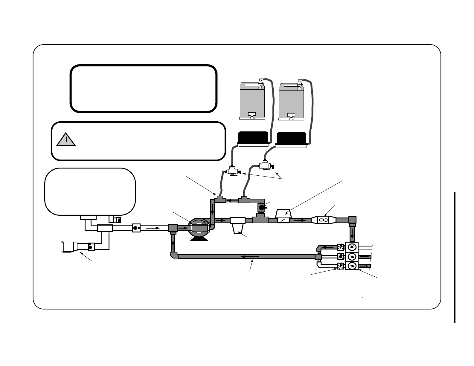
TYPICAL REFLOW
98-05010
Rev. - 1
A-4
PLUMBING DIAGRAM
DO NOT REFLOW TO THE MAIN TANK
WHEN OPERATING AN INJECTION
SPRAYER!
MAIN WATER TANK
Quick Fill
Port
SPRAYER
Main Water/Carrier
Pump
INJECTION
MANIFOLD
MICRO - TANK
Inline
Filter
Reflow line
MICRO - TANK
CALIBRATION VALVES
Calibration
Ports
BYPASS ADJUST
VALVE
REFLOW BYPASS
VALVES
CHEMICAL TANK ASSEMBLIES
A.3 REFLOW PLUMBING DIAGRAM
INJECTION PUMP ASSEMBLIES
Flow
Control
Valve
Flow
Meter
TASC-6000, 6300, 6600
To Spray Booms
Boom
Valves
Two way
Page 51

TASC-6000, 6300, 6600
A.4 FLUID OUNCES CONVERSION TABLE
1/8 Pint = 2 Fluid Ounces
1/4 Pint = 4 Fluid Ounces
1/3 Pint = 5.33 Fluid Ounces
1/2 Pint = 8 Fluid Ounces
2/3 Pint = 10.67 Fluid Ounces
3/4 Pint = 12 Fluid Ounces
1 Pint = 16 Fluid Ounces
1 1/2 Pint = 24 Fluid Ounces
2 Pints/1 Quart = 32 Fluid Ounces
2 1/2 Pints = 40 Fluid Ounces
98-05010
Rev. - 1
3 Pints = 48 Fluid Ounces
4 Pints/2 Quarts = 64 Fluid Ounces
5 Pints = 80 Fluid Ounces
6 Pints/3 Quarts = 96 Fluid Ounces
7 Pints = 108 Fluid Ounces
8 Pints/4 Quarts/1 Gallon = 128 Fluid Ounces
1 Liter = 33.8 Fluid Ounces
LIQUID MEASURE WEIGHT TABLE (WATER)
1 Pint Water @ 60F = 16 Fl. Oz. = 1.042 Lbs.
1 Quart Water @ 60F = 32 Fl. Oz. = 2.084 Lbs.
1 Gallon Water @ 60F = 128 Fl. Oz. = 8.337 Lbs.
(Note: Fluid Ounces are not = Dry Weight Ounces)
A-5
Page 52
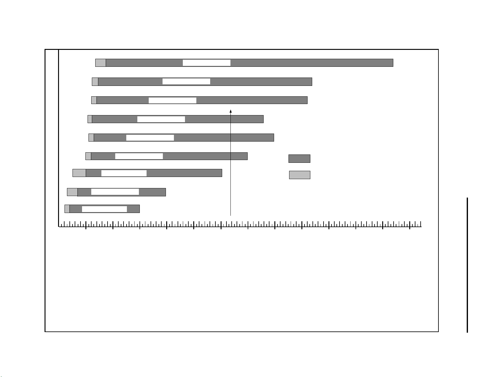
98-05010
Rev. - 1
PUMP/TUBE SELECTION CHART for TASC SERIES PUMPS
TASC 350 - 1/2" Tube
7.4
3.7
TASC 350 - 3/8" Tube
4.4
2.2
TASC 200 - 1/2" Tube
2.1
4
TASC 200 - 3/8" Tube
2.5
1.3
128
220
213
370
A-6
TASC 150 - 3/8" Tube
3
.5
PUMP NO.-TUBE SIZE
.3
.6
.2
.4
.2 .4 .6 .8
1.5
2
1
TASC 50 - 1/4" Tube
1.0
TASC 50 - 3/16" Tube
TASC 20 - 1/4" Tube
2 4 6 8
1 10 20 30 40 50 100 150 200 250 300 350 4000
TASC 100 - 3/8" Tube
100
53
29.9
(EXAMPLE 69.8)
20
150
MAX. FLOW RATE (Oz. / Min.)
EXAMPLE:
Max. Flow Rate = Max. Boom Width x Max. Speed x Appl. Rate x .00202
(Oz./Min.)
(Feet) (MPH) (Oz./Acre)
(Conv. Factor)
= 36 Ft. x 15 MPH x 64 Oz./Acre x .00202
= 69.8 Oz./Min.
Locate 69.8 on the horizontal axis of the chart, then draw a vertical line intersecting the Pump/Tube Sizes.
In this example, you would need at least a TASC #100 or larger pump.
NOTE:
Flow Ranges shown are
Optimum values.
Accurate control will be maintained at lower values.
A.5 TUBE SELECTION CHART
TASC-6000, 6300, 6600
Page 53

TASC-6000, 6300, 6600
98-05010
Rev. - 1
APPENDIX-B
SYSTEM OVERVIEW
B-1
Page 54

98-05010
TASC-6000, 6300, 6600
Rev. - 1
B.0. SYSTEM OVERVIEW
Mid-Tech has drawn upon many years of experience in electronically controlled chemical application to design and
build this spraying system. We rely on the experiences of our users as well as ourselves to help us continually improve
our systems. Please contact us to let us know what you like or don’t like about the TASC. We appreciate your comments, and THANK YOU for purchasing a MIDWEST TECHNOLOGIES Total Application Sprayer Control (TASC).
B.1. THE TASC SYSTEM CONTROLS BOTH CARRIER FLOW AND CHEMICAL INJECTION RATES
TASC is available in three different models, depending on the operator’s requirements. These models are the: TASC6000, TASC-6300, or TASC-6600.
®
Flow
RATE
.
Gal./
TASC-6000
TOTAL APPLICATION SPRAYER CONTROL
-Ac
MIDWEST TECHNOLOGIES, INC.
MID-TECH
ON OPERATE INC.
OFF SET- UP DEC.
CHEMICALS
%Rate
Appl. Rate
Chem. Rate
Chem. Applied
123456 789
BOOMS
Area
Speed
Scan
Test
Speed
DISPLAY SELECTOR
Total Applied
Distance
Prime
CARRIER
Width
RATE
CHEMICAL APPLICATORS
12
Flow
3
Gal./
Alt.Rate
ON
OFF
.
TASC-6300
TOTAL APPLICATION
SPRAYER CONTROL
-Ac
MIDWEST TECHNOLOGIES, INC.
MID-TECH
®
SET- UP
OFF
CHEMICALS CARRIER
%Rate
Chem. Rate
Appl. Rate
Chem. Applied
1234567 89
BOOMS
Area
Speed
Scan
DISPLAY SELECTOR
Total Applied
Width
Distance
Prime
Test
Speed
Flow
DEC.
RATE
CHEMICAL APPLICATORS
123
.
Gal./
4 5 6
-Ac
MIDWEST TECHNOLOGIES, INC.
Alt.Rate
ON
OFF
MID-TECH
TASC-6600
TOTAL APPLICATION
SPRAYER CONTROL
ON OPERATE INC.
®
OFF SET- UP
DEC.
CHEMICALS
%Rate
Chem. Rate Appl. Rate
Area
Speed
Scan
DISPLAY SELECTOR
Total Applied
Width
Distance
Prime
Test
Speed
Chem. Applied
123456789
BOOMS
CARRIER
ON OPERATE INC.
TASC-6000 is a basic sprayer flow control system. TASC-6000 performs both monitoring and control functions,
freeing the operator from the requirement to maintain a constant vehicle speed and a constant sprayer pressure. TASC6000 assures a constant and precise application rate for the material from the main tank. Because of its modular design,
a TASC-6000 can be upgraded to either a TASC-6300 or a TASC-6600.
TASC-6300 or 6600 are chemical injection controls as well as sprayer flow controls. These two units automatically
introduce and mix active chemicals into the main carrier flow during spraying operations. The TASC-6300 and 6600 are
simple, easy to use, and virtually automatic. TASC-6300 can simultaneously control up to three separate chemical
injection pumps, while TASC-6600 can control up to six injection pumps.
Chemicals are not mixed in the main tank when using either TASC-6300 or TASC-6600. The operator uses chemical
only where it’s needed and at just the rate necessary to do the job. The operator finds he is doing a more precise job of
application, with less wasted chemical, and minimum exposure to dangerous or toxic materials.
B.1.1. HOW A TASC-6000, 6300 or 6600 CONTROLS CARRIER APPLICATION RATE
TASC senses ground speed, active boom width, and carrier flow rate. When a change in ground speed or boom width is
detected, TASC changes the carrier flow rate to maintain a constant, pre-selected rate per area. An increase in ground
speed results in a proportional increase in flow rate. A decrease in ground speed results in a proportional decrease in
flow rate. Comparisons of flow rate, active boom width, and ground speed are made approximately four times each
second and corrections are made to the flow rate as soon as an imbalance is seen.
B-2
Page 55

TASC-6000, 6300, 6600
98-05010
Rev. - 1
B.1.2. HOW A TASC-6300 AND 6600 CONTROLS CHEMICAL APPLICATION RATE
The theory behind controlled, chemical injection spraying is simple. Each chemical is stored in a separate container until
it is actually applied. Chemical is injected into the carrier as needed using a precision metering pump. Injected chemical
mixes rapidly and thoroughly with the carrier before it leaves the sprayer through the nozzles.
A TASC-6300 or 6600 automatically maintains the desired chemical application rate by sensing changes in ground
speed or active boom width and adjusting the rate of chemical injection accordingly. For example, if the ground speed of
the sprayer increases or decreases, the injection pump speed increases or decreases accordingly to keep the amount of
chemical applied per unit area at a constant value. Likewise, as more boom sections are switched on or off line, the
injection pump speeds up or slows down accordingly, to assure the proper application rate. TASC makes these comparisons and adjustments approximately four times each second. The speed and accuracy of TASC allows it to precisely
control the application rate of each chemical being injected.
TASC CONTROL SYSTEM FLOW SCHEMATIC
Record Keeping
All Pertinent Sprayer Data
Data Logger/Printer
Hard Copy
RAM Memory
P.C. Compatible
Vehicle Ground Speed
Control Data
Data Printer
Hard Copy only
Active Boom Width
Control Data
Input Functions
TASC
Control Console
Controlled Output Functions
Carrier Product
Flow & Application Rate
Liquid Control Systems Dry Control Systems
Control Valve
(Liquid or Hydraulic)
Flow Sensor
(Liquid Flowmeter)
(Pump RPM Sensor)
Control Valve
(Hydraulic)
Flow Sensor
( RPM Sensor)
Operator Inputs
Set-Up & Active Control Data
Feed Back Control Data
Chemical Products
Flow & Application Rate
(up to 6 separate products)
Liquid Injection Pumps Granular Applicators
Metering Pump
Flow Sensor
(Shaft RPM Sensor)
Metering Device
(Star Wheel Applicator)
(Shaft RPM Sensor)
Flow Sensor
B-3
Page 56

98-05010
TASC-6000, 6300, 6600
Rev. - 1
B.2. TASC SYSTEM COMPONENT PARTS
There are seven major components in a complete TASC Injection Control System, a console, ground speed sensor,
flowmeter, flow control valve, boom interface cable, chemical containers, and injection pumps. Each of these components is described below so that the operator, will have a general understanding of how each of the parts performs its job.
-Ac
MIDWEST TECHNOLOGIES, INC.
Alt.Rate
ON
OFF
MID-TECH
TASC-6600
TOTAL APPLICATION
SPRAYER CONTROL
Boom Interface Cable
ON OPERATE INC.
®
OFF SET- UP
DEC.
CHEMICALS
CARRIER
%Rate
Chem. Rate Appl. Rate
Chem. Applied
Total Applied
Area
Width
Distance
Speed
Prime
Scan
Test
Speed
DISPLAY SELECTOR
1234567 89
BOOMS
Chemical Containers
Flowmeter
Speed Sensor
C
AB
Flow
RATE
Gal./
CHEMICAL APPLICATORS
123
4 5 6
TASC Control Console
.
Flow Control Valve
Chemical Injection Pumps
B.2.1. THE TASC CONTROL CONSOLE
The TASC Control Console is the heart of the system and actually performs three separate functions. The console is a
small computer with a sophisticated program developed by MIDWEST TECHNOLOGIES. The console continually
monitors ground speed, boom width, and current flow rate. As these values change, the console recalculates the required
carrier flow rate and the chemical injection rate of each injection pump and commands the necessary corrections.
Changes in valve settings and pump speeds are almost immediate.
The Control Console allows the operator to command rate changes “ON THE GO”. The operator has complete and
immediate control over the application rate of the main carrier and of each injected chemical. Rates can be altered
independently while the sprayer is operating.
The Control Console informs the operator about the status of the sprayer. TASC Control Console immediately warns the
operator if the system can no longer maintain accurate application. The warnings are both visual and audible, to attract
immediate attention. The large, backlighted LCD also displays instant readouts of carrier application rate and volume
applied, application rate and volume of each chemical applied, vehicle ground speed, active boom width, distance
traveled, and the total area covered while spraying.
B.2.2. FLOWMETER
TASC requires a flowmeter in the main boom feed line to sense and display carrier flow rate. The flowmeter is an
impeller device. This means a specific volume of liquid flowing through the sprayer rotates an impeller a specific
number of revolutions. TASC is able to count the revolutions of the impeller very accurately, allowing the console to
calculate the precise flow rate of the liquid in the main boom supply line.
Sometimes a sprayer is already equipped with a flowmeter. TASC can usually be adapted to work with existing flowmeters, as long as they measure the total liquid flow to the sprayer nozzles. Check with your dealer, or the factory, regarding the adaptability of a specific flowmeter.
B-4
Page 57

TASC-6000, 6300, 6600
98-05010
Rev. - 1
B.2.3. FLOW CONTROL VALVE
TASC requires a flow control valve in the main boom supply line to provide automatic carrier control. This valve
throttles the carrier flow in response to commands from the control console. To be effective in controlling carrier flow,
the valve must be fast acting and precise in its movements.
The flow control valve may take the form of a hydraulic flow control valve controlling the flow rate by controlling the
speed of the product pump.
Sometimes a sprayer is already equipped with an electronically controlled flow control valve. If the valve meets the
necessary speed and precision requirements, it can be adapted for use with TASC. Check with your MID-TECH dealer,
or the factory, regarding the adaptability of a specific valve.
B.2.4. GROUND SPEED SENSOR
TASC requires an accurate ground speed sensor. A magnetic pickup, wheel sensor is standard equipment. This sensor,
mounted on a non-driven wheel, has proven to be very accurate and dependable for most spraying operations.
An optional radar ground speed sensor is available from MIDWEST TECHNOLOGIES for applications where wheel
slippage and variations in ground conditions are a concern. The radar sensor does not depend on ground contact and is
unaffected by these variables.
Some sprayers may already be equipped with a ground speed sensor. If the speed sensor meets the accuracy requirements, it can be adapted for use with TASC. Check with your MID-TECH dealer, or the factory, regarding the adaptability of a specific sensor.
B.2.5. BOOM INTERFACE
TASC needs to know when each boom section is activated, in order to adjust chemical flow rates appropriately. The
console recognizes the activation of each boom section, whenever it receives a positive voltage on the boom interface
connection corresponding to that boom position. The console is capable of sensing and responding to nine separate
boom sections. The console can also sense the operation of an independent, status switch which would result in a shut
down of all chemical injection pumps and a selectable response by the Flow Control Valve (position held or full closure). Finally, the Boom Interface can be equipped with an optional Ground Speed Override switch.
The standard TASC System is supplied with a five position boom interface cable. The cable plugs directly into the rear
of the TASC console and allows connection to up to five boom sections, an optional ground speed override switch and
an optional status switch. A nine boom interface cable is available for larger sprayers.
An optional boom control switch panel, with interface, serves those sprayers not already equipped with electrical boom
control devices. The switch panel can power up to nine boom control valves, and acts as an interface for an independent
status switch. The switch panel plugs directly into the back of the TASC Control Console and receives power from the
vehicle battery. Models are available to control both solenoid and rotating valves.
B.2.6. PRECISION INJECTION PUMPS
MID-TECH uses precision peristaltic pumps to meter individual chemicals into the main boom supply line of the
sprayer. Peristaltic pumps use rollers to squeeze a flexible tube, forcing a volume of fluid through the tube ahead of the
advancing roller. Each pass of a roller over the tube forces out a consistent volume of chemical. The inherent precision
and broad operating range of the peristaltic pump makes it work extremely well as the metering device used with TASC.
The pumps MIDWEST TECHNOLOGIES supplies with TASC include their own DC motor and motor control module.
The motor control module uses modern, solid state electronics to switch power to the motor directly from the battery.
Special, high torque motors are used to provide positive rotation at all speeds.
B-5
Page 58

98-05010
TASC-6000, 6300, 6600
Rev. - 1
B.2.7. CHEMICAL CONTAINERS
MIDWEST TECHNOLOGIES has designed special chemical containers for use with chemical injection sprayers. These
containers are available in either 7.5 gallon or 25.0 gallon capacities and can be equipped with optional agitation
devices. The tanks are mounted in optional stainless steel racks and are easily removed from the vehicle for filling,
cleaning or storage. The containers are equipped with chemical resistant couplings for fast, safe, positive, connection to
the injection pump intake hoses.
The patented tanks are unique features of all MIDWEST TECHNOLOGIES injection spraying systems, including
TASC. These portable chemical containers offer tremendous flexibility to the operator, since switching from one
chemical to another is as easy as removing one container and replacing it with another holding a different chemical.
Exposure to raw chemical is kept to a minimum.
Some sprayers may already be equipped with separate holding tanks for raw chemicals. If the operator desires, these can
be plumbed directly to the injection pumps.
B-6
Page 59

TASC-6000, 6300, 6600
98-05010
Rev. - 1
APPENDIX-C
INSTALLATION
C-1
Page 60
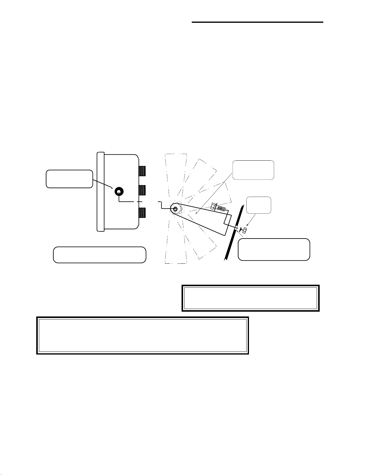
98-05010
TASC-6000, 6300, 6600
Rev. - 1
C.0. INSTALLATION
C.1. CONTROL CONSOLE INSTALLATION
The Control Console should be located inside the vehicle cab, when possible. It can be mounted on or below the dash, or
any other location where it is accessible to the operator without diverting or obstructing his view. The mounting bracket
may be attached to the console with the mounting face of the bracket up or down as required.
C.1.1. CONSOLE MOUNTING
After selecting a suitable location for the console, drill two 9/32" diameter mounting holes, using the mounting bracket
as a template to mark the locations. Attach the mounting bracket to the mounting surface using two 1/4" bolts, lock
washer and nuts. Then mount the console to the mounting bracket using the well nuts and the knobs supplied.
BRACKET
Use the Wellnuts and
Knobs provided to attach
the Control Console to the
Bracket.
Can be attached at a
VARIABLE ANGLE
1/4" Bolt,
Flatwasher,
Lockwasher,
& Nut
CHECK FOR DRILLING
TASC CONTROL CONSOLE
SIDE VIEW
CLEARANCE BEFORE
DRILLING 9/32" HOLES
CAUTION: Make certain the opposite side of the
drilling surface has plenty of clearance for the
fasteners and is free of wiring or hoses.
WARNING: FOR POSITIVE GROUNDED VEHICLES; DO NOT select a
mounting location that will allow the console rear panel or the front panel toggle
switches to come in contact with the vehicle frame. The parts are negatively grounded
and MUST NOT contact the frame of a positively grounded vehicle.
NOTE: If the control console is to be installed on a vehicle in a location which is unprotected from weather or chemicals, the following precautions must be followed.
A. Install the console so that the front panel is tilted up no more than 45 degrees and no less than 10 degrees. This
will allow any water that gets inside the console to drain through the holes in the back of the case.
B. The console electronics are sealed to prevent damage from moisture, however if the console will be exposed to
weather, it should be covered when not in use. The best cover is one which would protect the console from rain
and yet allow for air movement from below. A plastic bag sealed tightly around the console is NOT recommended, as this can cause excessive moisture and heat build up inside the console.
C-2
Page 61
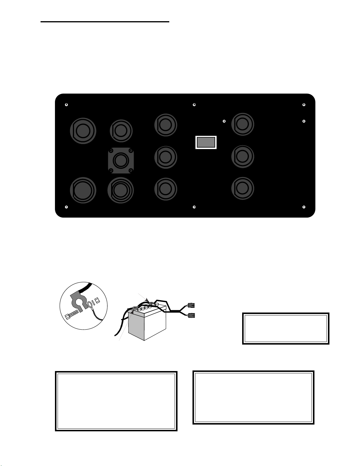
TASC-6000, 6300, 6600
98-05010
Rev. - 1
C.1.2. CONSOLE CABLE ROUTING
Console Cable routing is important. There are up to eleven connector positions on the back of the console; Power, Pump
Controls #1 to #6, Ground Speed, Boom I/O, Flow Control, and serial I/O. Depending on the TASC model, some
connector positions may not be present. The power cable is marked with a “Connect to +12 Volts Only” label, all other
cables are labeled and connect to the corresponding position on the rear of the console (See Appendix A). The connectors are keyed so they will only mate in the proper position.
CONTROL
4
5
6
POWER
GROUND
SERIAL
I/O
SPEED
FLOW
CONTROL
BOOM
INTERFACE
CONTROL
1
2
3
Rear view of the TASC Control Console
Determine the best location for the cables to exit the cab. If an existing exit point is not available, drill or punch a 11/4"
to 11/2" dia. hole in the cab. The hole must be protected with a grommet or other material to prevent sharp edges from
cutting into the cables. After all cables have been properly routed and secured, seal the entry point with foam rubber, or
other appropriate material, to keep dust out of the cab.
CONNECT ALL POWER LEADS DIRECTLY TO THE VEHICLE BATTERY
12 Volts D.C.
Positive Terminal
Chassis Ground
Negative Terminal
DO NOT SUBSTITUTE HIGHER AMPERAGE FUSES
CAUTION: The Console Power Cable MUST
be connected directly to the vehicle battery (12
VDC only). This provides electrical noise protection to the console. Be sure that the red
(fused) wire is attached to the positive terminal
of the battery and the black wire is attached to
the negative terminal.
Battery
Power
Cable
AB
AB
CAUTION: DAMAGE TO THE
TASC SYSTEM MAY OCCUR,
IF POLARITY IS REVERSED!
NOTE: Route all cables carefully, avoiding
moving parts, excessive heat and exposure to
tree limbs, stubble, or other debris. Allow enough
slack at all pivot points to guard against pinching or stretching the cables. Finally, secure the
cables in place with tie wraps and/or cable clamps.
C-3
Page 62

98-05010
>12 inches
> 6 inches
FLOWMETER/
PRESSURE SENSOR
TO BOOMS
MAIN PRODUCT
PUMP
BYPASS LINE
AUTO RANGE
VALV E
R
Signal cable
to console
PUMP DISCHARGE
TASC-6000, 6300, 6600
Rev. - 1
C.2. FLOWMETER INSTALLATION
The installer should refer to the detailed instructions shipped with the particular device being installed. MIDWEST
TECHNOLOGIES recommends that these specific installation instructions be attached to this manual for future reference. There are, however, a few general mounting tips which should be considered for any flowmeter installation.
The accuracy of the flowmeter depends on a smooth, unobstructed flow through the device. Every effort should be made
to mount the flowmeter in a straight section of the main boom supply line with at least twelve inches of straight flow
upstream from the device and at least six inches of straight flow downstream from the device. Sharp bends in the flow
stream caused by valves, kinks, elbows, tees, etc., can seriously degrade the performance of the flowmeter. Additionally, if the flowmeter being installed is sensitive to the direction of flow, it will be marked with an arrow. These devices
should always be installed with the arrow pointing in the direction of normal flow.
NOTE: THE FLOW METER MUST
BE MOUNTED SO THAT IT WILL
DRAIN COMPLETELY WHEN THE
SPRAYER IS NOT OPERATING!
The flowmeter must provide the TASC Control Console with a continuous measurement of total liquid actually discharged by the sprayer. This includes both the main carrier and the injected chemical, after the two are mixed. To
accomplish the required measurement, the flowmeter must be installed in the main boom supply line, upstream from the
individual boom shut off valves and downstream from the flow control valve and pump bypass line, if used (See figure
above).
The flowmeter should be installed in a location that will physically protect it from damage and allow liquid to drain
away when the sprayer has been flushed and secured at the end of an operating day. Keep the flowmeter from lying in
a low section of tubing. This is particularly important in cold weather, when water could freeze in the flowmeter and
damage the internal mechanism. It is also important when applying chemical suspensions which may settle and obstruct
the flowmeter if they don't drain away. A straight, vertical section of the main boom supply line, is the ideal location for
the flowmeter. Firmly support the main boom supply line in the vicinity of the flowmeter to protect it from deforming
and vibration.
C-4
Page 63

TASC-6000, 6300, 6600
98-05010
Rev. - 1
C.3. FLOW CONTROL VALVE INSTALLATION
There are a number of different types of flow control valves capable of operating with the TASC System. The installer
should refer to installation instructions supplied with each device for information that applies specifically to that device.
Mid-Tech recommends that these specific installation instructions be attached to this manual for future reference. There
are, however, a few general mounting tips which should be considered for any flow control valve installation.
Since the valve is used to control the liquid flow to the spray boom, it must be mounted downstream from the pump
bypass line and at least twelve inches upstream from the flowmeter. The valve should not be mounted in a low spot in
the line, where water or sediment can collect and obstruct the valve by freezing or jamming. Select a location that will
protect the valve from physical damage.
The cable connecting the flow control valve to the TASC Control Console should be routed carefully to afford maximum protection from abrasion or breakage. The flow control valve power cable must be connected directly to the
vehicle battery (12 VDC only). Attach the red lead (fused) to the positive post and the black lead to the negative post of
the battery.
C.4. GROUND SPEED SENSOR INSTALLATION
A variety of devices are capable of providing the actual ground speed information required by the TASC Control
Console. The installer should refer to the detailed installation instructions provided with the particular device being used.
Attach these specific installation instructions to this manual for future reference. There are a few general tips the installer
should be aware.
Wheel Sensor: Be sure to mount the sensor on a non-driven wheel, making every effort to protect the cabling from
physical damage during field operations. Make sure the sensor magnets are securely attached, and that they are mounted
in the proper alternating sequence.
Radar Sensor: The most secure mounting is to use a metal bracket as described in the instructions for mounting to the
frame of the vehicle. Make sure there are no moving or rotating parts of the vehicle exposed in the field of view of the
radar sensor.
Speedometer Sensor: If installed on a vehicle with a two speed axle, be sure the sensor is mounted between the ratio
corrector and the speedometer head.
C.5. BOOM CONTROL SWITCHES AND INTERFACE
TASC is supplied with a boom interface cable (standard) or a boom control switch box (optional).
C.5.1. BOOM CONTROL SWITCH BOX
Using the Boom Control Switch Box as a template, locate it conveniently close to the sprayer operator and close enough
to the TASC Control Console for the connecting cable to reach. Drill mounting holes and firmly attach the switch box to
the vehicle. (In some cabs, it may be necessary to fabricate a mounting bracket for the switch box.) (Always check
behind the surface that you are drilling to make sure that there are no wires, tubing, etc. that might be damaged!)
The Boom Control Switch box is equipped with four cables (Boom I/O, Power, Boom Valve, and Implement Status).
The Boom I/O cable plugs into the Boom I/O position on the back of the console. Carefully route the power cable to the
accessory power (12 VDC only). Connect the red (fused) wire to the positive terminal and the black wire to the negative
terminal. The third cable ends with up to nine pairs of wires, numbered one through nine, and supplies positive and
negative power to the individual boom valves. Carefully route this cable to the boom valves and connect the wire pairs
to the valves in sequence. The status cable is terminated with a 3 pin connector (used for the status switch) and a male /
female spade pigtail (used for electrically activated carrier pumps). When the status or pump switch is OFF, the console
stops the chemical injection pumps and demands a selectable response from the Flow Control Valve. If a status or
C-5
Page 64

98-05010
TASC-6000, 6300, 6600
Rev. - 1
pump switch is not used, the shorting plug must be installed or TASC will not operate. The optional Ground Speed
Override switch should be mounted conveniently for the operator's use. This switch can be either hand or foot operated.
Check to insure all cables are protected from abrasion and breakage, and secure with cable ties or clamps.
C.5.2. BOOM INTERFACE CABLE
If your sprayer already has switches for controlling the boom valves, you can continue to use those switches. Instead of a
Boom Control Switch box like that described in the previous section, you would use a Boom Status Cable to monitor the
status of the boom valves.
The connector on one end of the Boom Interface Cable plugs into the Boom I/O position on the back of the TASC
Control Console. The other end of the cable has up to nine wires that have been terminated with a female spade terminal.
These wires are individually numbered from one through nine. The installer must decide which of the booms will be
designated number one. Then, each numbered wire from the boom interface cable must be connected to either, the boom
on/off switch or the boom valve itself, in the appropriate sequence. Each wire must be connected to a terminal that is
normally zero volts or open when the boom section valve is closed (OFF) and powered (12 V. DC) when that particular
boom section valve is opened (ON).
Each Boom Interface also has an Implement Status Connector. For chemical injection to occur, the
status switch must provide (+12 VDC) to the white or green wire. If a status switch is not used, the
shorting plug must be installed, otherwise the TASC System will not operate properly.
The wire ends should be connected first and then routed back to the TASC Control Console. Unused wires should be
taped and secured to prevent damage. Check to insure that the cable is protected from abrasion and breakage, and secure
with cable ties or clamps. Do not run the Boom I/O cable near a two way radio antenna or other source of electrical
noise! Insert the connector into the Boom I/O position on the back of the console (See Appendix A).
The optional Ground Speed Override switch should be mounted conveniently for the operator's use and the excess cable
coiled up and secured in a protected location. This switch can be either hand or foot operated.
C.6. INJECTION PUMP INSTALLATION
The injection pumps supplied with a TASC System are precision peristaltic pumps. If other approved pumps are
installed, the installer should refer to the detailed installation instructions provided with those alternate injection pumping devices. MIDWEST TECHNOLOGIES recommends that the specific installation instructions be attached to this
manual for future reference.
C.6.1. SELECTING THE CORRECT PUMP FOR THE APPLICATION
Use the following formula to determine the required pump capacity for the application. Then check to be sure the TASC
System has been provided with the appropriate pump.
Pump Cap. = Max. Boom Width x Max. Speed x Chemical Rate x (.00202)
(Oz./Min.) (Ft.) (MPH) (Oz./Acre)
Example: A sprayer with 35 ft. booms, traveling at a maximum speed of 7 mph and applying 1 quart of chemical per
acre would require a maximum pump capacity of 15.8 Oz./Min. (i.e. 35 ft. x 7 mph x 32 oz/ac x .00202 = 15.8 Oz./
Min.). Referring to the Pump/Tube Selection Chart in Appendix A we find that a MID-TECH Model-20 pump would be
sufficient for this chemical. However; if you needed to apply 64 oz./ac. of chemical, you would need the MID-TECH
Model-100 pump, (i.e. 35 x 7 x 64 x .00202 = 31.7, which exceeds the capacity of the smaller 20 Oz./Min. pump).
Variations in speed and boom widths will also affect the pump capacity required.
C-6
Page 65

TASC-6000, 6300, 6600
98-05010
Rev. - 1
NOTE: Select the pump with a maximum capacity the next size larger than the
calculated capacity required. This will insure that the TASC system will have
enough capacity to provide precise control over the expected range of operating
conditions.
C.6.2. INJECTION PUMP LOCATION
Injection pumps must be located as close as possible to the point where the chemicals will be injected into the main
boom supply line. Consideration for the location of the chemical containers must also be given, keeping the distance
from the injection pump to the chemical container to a minimum. There are two recommended locations for injecting the
chemicals into the carrier fluid.
A. Preferred Location: The inlet point of the main pump is the preferred location. This allows for excellent mixing
of the chemicals through the main pump. If this location is selected the sprayer must be plumbed so that no
mixed material can return to the main tank (See plumbing diagram in Appendix A). If sparging is necessary,
MID-TECH recommends installing a separate sparging pump. This has the added advantage of maintaining a
constant sparge flow, regardless of variations in ground speed or spraying rates.
B. Alternate Location: If sparge line agitation of the main tank is required, the injection point needs to be located
between the sparge line and the boom section valves. This can be accomplished by using an Auxiliary pump to
inject the metered chemicals from the Peristaltic Injection pumps into the relatively high pressure main boom
supply line.
NOTE: Since tank mixing is no longer required with this system, most
sprayers will not need a sparge line. MIDWEST TECHNOLOGIES recommends that sprayers equipped with a sparge line (Main tank agitation return
line) be plumbed as a pump recirculating only sprayer, when a TASC
injection system is installed.
C.6.3. CLEARANCE AND MOUNTING OF INJECTION PUMPS
Once the best location for the injection pump has been selected, plan to orient the assembly so that the injection pump
assembly cover is easily opened, allowing access for inspecting and changing the tubes. Be sure that the injection pump
assembly is protected from inadvertently being stepped on or bumped. Use the pump mounting base as a template to
mark the mounting hole locations. NOTE: Secure each pump firmly to eliminate vibration and possible damage to
the connecting hoses and cables.
C.6.4. INJECTION PUMP CABLE ROUTING
Each injection pump comes with two cables, one pump control cable and one pump power cable. NOTE: Route all
cables carefully, avoiding moving parts, excessive heat and exposure to tree limbs, stubble, or other debris. Allow
enough slack at all pivot points to guard against pinching or stretching the cables. Finally, secure the cables in place
with tie wraps and/or cable clamps.
Pump Control Cables: The operator needs to decide which pumps are to be designated #1 , #2, etc., and then mark the
cable tags accordingly, (use a permanent ink - water proof marker). Carefully route the cable to the console and connect
to the corresponding console connector. (See Appendix A)
Pump Power Cable: Route each power cable to the vehicle battery (12 VDC only) and attach the red lead (fused) to the
positive post and the black lead to the negative post of the battery.
C-7
Page 66

98-05010
TASC-6000, 6300, 6600
Rev. - 1
C.6.5. PRECISION PERISTALTIC INJECTION PUMP TUBING INSTALLATION
Each injection pump comes with two appropriately sized tubes and a bottle of Tube Lube. To install the tubing, remove
the retaining hardware from the pump cover and gently pry the cover off, (Do Not Force). Take one of the tubes and
coat approximately 12" of its midsection with a liberal portion of the Tube Lube. Slip this lubricated section into the
inner pump housing, between the rollers and the pump housing. Replace the outer pump housing and retaining hardware,
(Do Not fully tighten the retaining hardware).
Connect the tubing to the two hose barb fittings on the base of the pump assembly, and tighten securely to prevent air
leaks in the chemical lines. The top of the pump is the suction side and must be connected suction line, (see Tubing
Installation Decal inside the pump cover). Adjust the position of the tubing, avoiding sharp bends or kinks in either the
suction or discharge lines. Trim a little off of the discharge end, if the tubing appears to be too long. Tighten the retaining hardware on the outer pump housing.
ROTATION
Randolph Pumps
Diagram shows tubing forms to outer wall.
Clamp bar should be "snug" (not too tight).
Masterflex¨ Pumps
Diagram shows tubing forms to outer wall.
Place extra hose clamp at inlet (suction side) of the pump to
prevent the Python tubing from moving inside the pump housing.
WARNING: BE SURE THE CHEMICAL LINES
ARE POSITIVELY SHUT OFF BEFORE REMOVING THE TUBES FROM THE PUMP
HOUSINGS. THIS WILL KEEP CHEMICAL
FROM SIPHONING INTO THE MAIN TANK
OR WATER FROM SIPHONING INTO THE
CHEMICAL TANKS THROUGH THE RELAXED TUBES.
SUCTION
CLAMPS
Place extra hose clamp at inlet (suction side) of the pump to
prevent the Python tubing from moving inside the pump housing.
SUCTION
Secure the tube to hose barbs using hose clamps.
DISCHARGE
ROTATION
DISCHARGE
NOTE: After use, the pump should be thoroughly flushed with clean water and have the
tubing removed from the pump housing, (leave
the tubing connected to the two fittings). This
will prevent the tubing from deforming under
the pressure of the rollers.
C-8
Page 67

TASC-6000, 6300, 6600
98-05010
Rev. - 1
C.7. CHEMICAL CONTAINERS
Mid-Tech tanks are ideal containers for handling raw chemicals. Alternative containers can also be used, such as
permanently mounted cone bottomed tanks. Whatever chemical container will be used, it is important to select a large
enough tank to cover a normal area at the expected application rates. This is particularly true with permanently mounted
chemical tanks. Since Mid-Tech tanks are easily removed and exchanged in the field, spare tanks can be available to the
operator.
CAUTION: Alternate chemical tanks (other than MID-TECH tanks) must
be fitted with shut off valves at the bottom of the tanks.
C.7.1. MOUNTING AND PLUMBING MID-TECH TANKS
MIDWEST TECHNOLOGIES provides an optional stainless steel rack for securing Mid-Tach tanks to the spraying
vehicle. The largest rack is approximately 18 inches by 19 inches and has been punched with holes for 5/16" carriage
bolts. Each large rack will hold two 7.5 gallon or one 25 gallon Mid-Tach tank. A smaller rack is available for a single
7.5 gallon Mid-Tach tank. The smaller rack is approximately 18 inches by 9.5 inches. The Mid-Tech tanks fit tightly into
the racks and are secured in place with a tab and clip mechanism.
The rack should be mounted to the vehicle so that it is level during normal vehicle operation. The tanks should be
located as close to the injection pumps as possible to keep product lines short. The rack should be mounted in such a
manner that the operator can easily lift the tanks in and out when changing. In some instances it may be necessary to
fabricate additional support for the tank rack.
7
26
1
6
24
2
6
22
1
5
2
20
5
18
1
4
2
16
4
14
1
3
2
LITERS
12
3
U.S. GALLONS
10
1
2
2
8
2
1
6
1
2
4
1
1
2
2
TANK MOUNTING BASE
Midwest Technologies Inc.
Springfield,
Ill.
C-9
FRESH WATER
RINSE
INJECTION PUMP
Page 68

98-05010
TASC-6000, 6300, 6600
Rev. - 1
The Mid-Tech tanks comes complete with a chemical resistant, quick disconnect coupler. The product line between the
tanks and the injection pump should be at least 1/8 inch larger than the tubing size in the pump, and it must be fitted with
a mating coupler (available through MIDWEST TECHNOLOGIES). It is also recommended that a nearby fresh water
source be fitted with a quick disconnect nipple similar to that on the Mid-Tech tank. The injection pump feed line can
then be disconnected from the tank and quickly connected to a fresh water source for flushing the injection system.
C.7.2. GENERAL SUGGESTIONS FOR PLUMBING CHEMICAL TANKS
Line sizes should be at least 1/8" larger than the tubing size for the injection pump. As a general rule keep all plumbing
as short as possible, long lines will affect pump capacities and make calibration difficult. Try to keep the bottom of the
tank and the injection pump on about the same level, or the tank slightly above the pump. Too great a difference in
levels between the tanks and the pumps (where the pumps are mounted higher on the vehicle than the tanks) can result in
reduced maximum pumping rates.
The Peristaltic Injection Pump draws chemical from the chemical container by creating a vacuum at the suction side of
the pump. In some cases, this vacuum is strong enough to pull air into the suction line through fittings that appear
“tight”. Air leaks adversely affect the calibration of the pump, since air bubbles take up space that should be occupied by
chemical. This phenomena is most pronounced at low pumping rates and typically shows up as under application in the
field. Ensure that all fittings are sealed with a good quality, liquid pipe dope and are properly tightened, especially the
suction lines. Make sure that hose barbs are clamped tightly.
C-10
Page 69
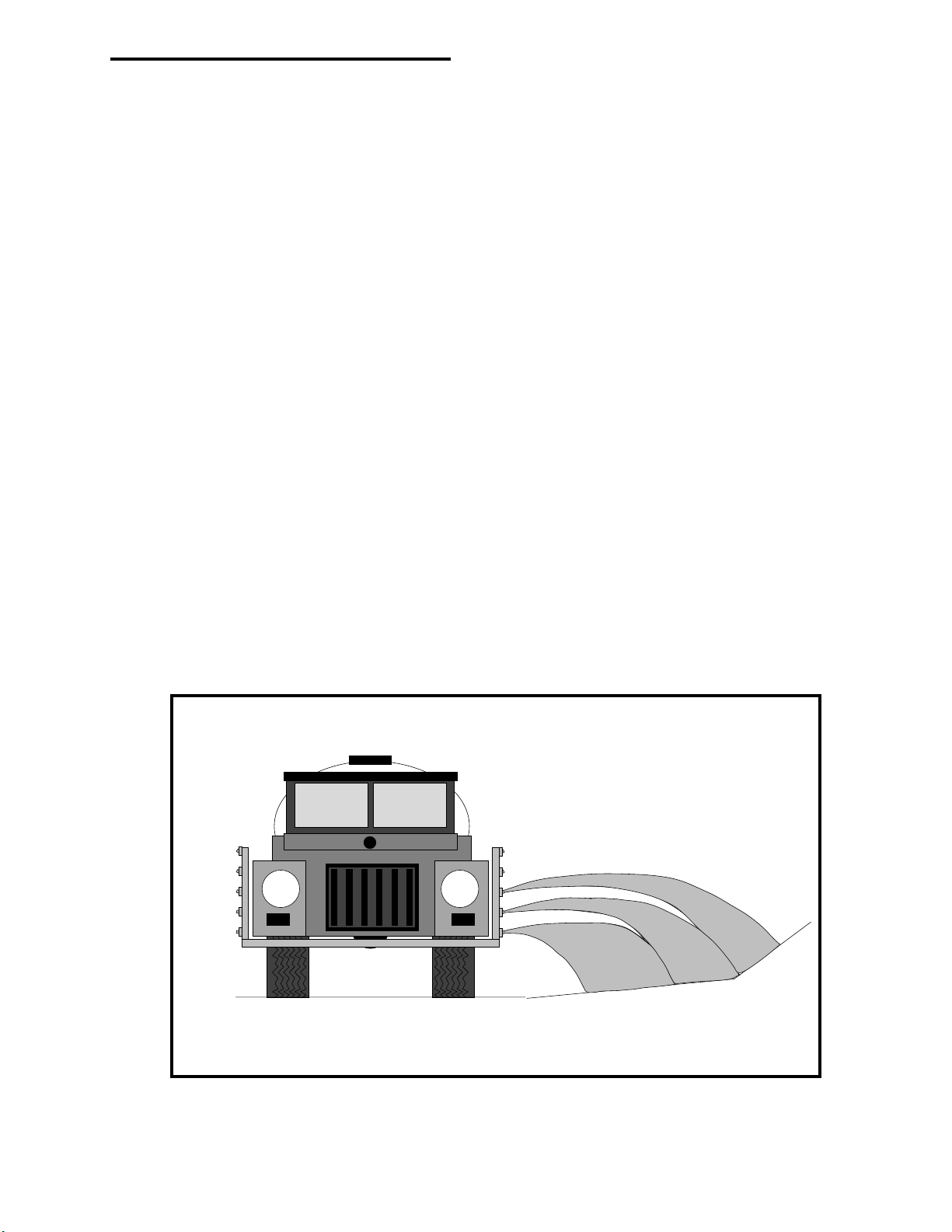
TASC-6000, 6300, 6600
APPENDIX-D
ROADSIDE/HANDGUN
98-05010
Rev. - 1
OPERATION
D-1
Page 70
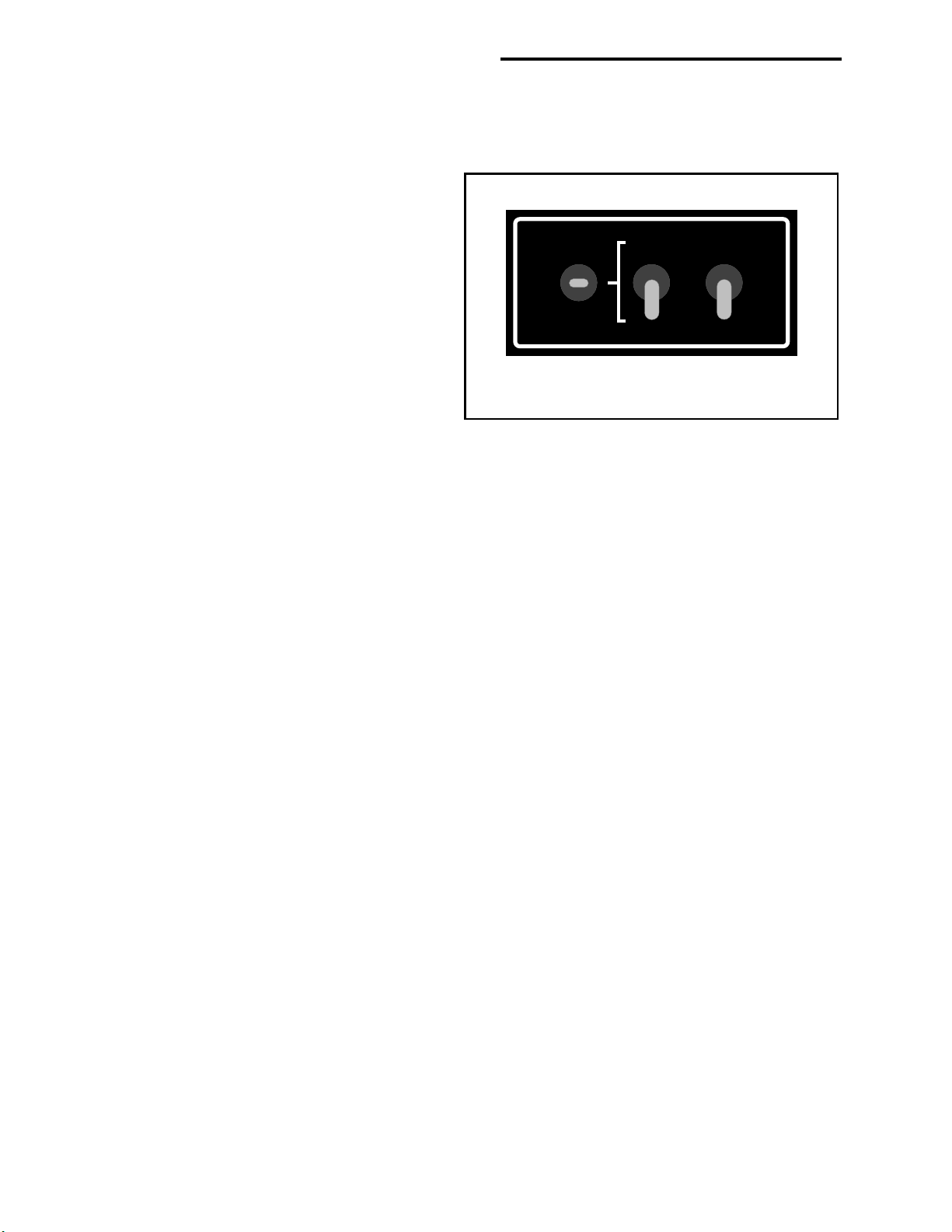
98-05010
TASC-6000, 6300, 6600
Rev. - 1
D.0. TASC ROADSIDE/HANDGUN OPERATION
TASC roadside spraying operations require a special boom control switchbox or boom interface cable to take advantage
of some of the features of the TASC console. Additionally an optional flow switch and cable is needed if a Handgun is
to be used.
Example 405-0093 Switch Panel
D.1 Modes of Operation
Ground Speed
Override
D.1.1 Normal
In the Normal Mode, the TASC console can control the
carrier and chemical injection pumps in any one of the
following manners (See Sect. D.3 for details.):
'B' Width Normal
Auto
'C' Width
Handgun Off
1. In Auto operation, the carrier and chemical rates
are programmed to give a constant per acre (ha.)
Boom
Switch
Mode
Switch
Ground
Speed
Override
application rate regardless of speed. As a result,
if you speed up the pressure goes up, and if you
slow down the pressure goes down.
2. In Auto "Pressure" operation, the carrier is maintained at a constant pressure regardless of ground speed or
booms On / Off. This results in the carrier rate in gal. / acre (l/ha.) decreasing with higher speeds, and increasing with lower speeds. The chemical injection pumps will continue to respond to changes in ground speed or
booms On / Off, thereby maintaining a constant chemical application rate per acre (ha.)
3. In using "Special Purpose Boom Widths" (Alternate Widths “B” or “C”), the chemical injection pumps control
to the programmed “B” or “C” width, ignoring the actual boom widths programmed and turned on. This is
commonly used to spray very steep up and down slopes where the normal programmed boom widths may not
accurately reflect the area actually being sprayed.
D.1.2 Handgun
In the Handgun Mode, the chemical injection pumps start and stop in response to the start of carrier flow sensed by a
flow switch. Chemical injection will occur only when the handgun trigger is pulled and flow is established. All booms
must be turned off for the Handgun mode to operate. The carrier and chemical injection pumps are controlled in any one
of the following manners:
1. The carrier rate is programmed into the TASC console in gallons (liters) per minute and the console controls the
carrier rate with an optional Auto-Range valve. Chemical rates are entered as "ounces per 100 gallons (liters
per 1000 liters)" of carrier or as a ratio of the carrier rate, as measured through the flowmeter.
2. The carrier rate is set to 0.0 (Manual Override) and the operator controls the flow through the handgun with the
Inc / Dec switch on the console, or with the Handgun trigger. The chemical rates are entered as "ounces per
100 gallons (liters per 1000 liters)" of carrier or a ratio of the carrier, as measured through the flowmeter.
3. The operator sets the nominal carrier flow rate through the Handgun as a “Test Speed” and the console controls
the chemical injection pumps at the rate or ratio programmed for them, regardless of the actual flow in the
handgun line.
D-2
Page 71

TASC-6000, 6300, 6600
98-05010
Rev. - 1
D.2. HANDGUN MODE OPERATION
D.2.1. HANDGUN MODE, SET-UP FUNCTIONS
To put the TASC in the Handgun mode:
A. Set the switches on the Boom Control Switch Panel as follows:
Boom Width Switch Auto
Mode Switch Handgun
Ground Speed Override Switch Off
B. Turn the TASC power "ON" and put the mode selector switch to "SET-UP".
The following programing functions are available in the TASC console:
SPEED: An "Err" message will appear (GSO is not available in the handgun mode).
AREA: Area will not accumulate in handgun mode.
CHEMICALS, CHEM. APPLIED: This is the pump calibration number for each injection pump (see section 2.8).
CHEMICALS, CHEM. RATE: With pump switch in the "ON" position, program the rate as ounces per 100 gallons of
carrier (use the INC/DEC switch to set this rate). With pump switch in the "ALT" position, the display will read as a
ratio (i.e. 1:100, gal:gal, or oz:oz, chemical:carrier). The rate can be programmed with pump switch in either position.
CHEMICALS, % RATE: Use the INC/DEC switch to set the desired rate change % for chemicals or carrier.
CARRIER APPL. RATE: Use the INC/DEC switch to set the desired carrier rate in gallons per minute.
CARRIER TOTAL APPLIED: The flow meter calibration number (section 2.6).
WIDTH: The message "none" will appear (boom width is not used in the handgun mode).
DISTANCE: The distance calibration number (section 2.7).
PRIME: The prime volume for each pump (section 2.8.4).
TEST SPEED: Using the INC/DEC switch, set a test flow rate in gallons per minute (this rate is required before pumps
can be accurately calibrated).
SCAN: An "Err" message will appear (there is no programming in SCAN).
D.2.2. HANDGUN MODE, OPERATE FUNCTIONS
Now put the TASC mode selector switch to "OPERATE". The following programing functions are available in the
TASC console:
SPEED: This is a direct reading of ground speed.
AREA: Area will not accumulate in the handgun mode.
CHEMICALS, CHEM. APPLIED: Accumulated ounces as they are applied, switches to hundredths of gallons after
256 ounces are accumulated.
CHEMICALS, CHEM. RATE: This register will indicate the programmed standard rate (oz per 100 gallons) with the
switch "ON". With pump switch in the "ALT" position, the display will read as a ratio (i.e. 1:100, gal:gal, or oz:oz,
chemical:carrier).
CHEMICALS, % RATE: Allows changing chemical injection rates a preset percentage (section 3.4.2.1).
CARRIER APPL. RATE: Displays target carrier application rate. Actual carrier flow rate in gallons per minute will be
displayed once flow is established. The INC/DEC switch will change the carrier rate by the percentage amount
programmed in the "Chemicals, % Rate" register (injected rates will not be affected).
CARRIER TOTAL APPLIED: Accumulated gallons applied.
WIDTH: "none" (boom widths are not used in the handgun mode.)
DISTANCE: Accumulated distance in feet or miles.
PRIME: Used for priming the injection pumps (section 3.5).
TEST SPEED: The gallons per minute programmed in the "SET-UP" mode is displayed.
SCAN: Scans information in the accumulators and registers.
D-3
Page 72

98-05010
TASC-6000, 6300, 6600
Rev. - 1
D.2.3. HANDGUN MODE, SPECIAL CONSIDERATIONS:
A. Pump Calibrations: The speed of the injection pumps during calibration is determined by the programmed test speed
("gallons per minute" or "liters per minute") and the programmed chemical application rate ("ounces per 100 gallons"
or liters per 1000 liters") or ratio ("gallons per gallon" or liters per liter). Set these numbers to your typical operating
conditions before doing the pump calibrations.
B. The injection pumps will operate at the speed necessary to apply the correct amount of chemical according to the
programmed carrier application rate, regardless of small variations in the actual carrier flow rate. (Large variations in
the actual flow rate lasting more than 5 seconds will cause an error shutdown of the sprayer). Thus, chemicals will
always be applied correctly, even if there is variation in the carrier output. (If the carrier rate is set to 0.0, see the
Manual Override of Flow Control Valve, Section D.2.5.)
C. Booms are not used in the handgun mode. If the TASC senses a boom "ON" condition it will indicate an "Err" and
will stop the injection pumps and close the flow control valve.
D. The initial response of the flow control valve to the selection of the handgun mode is to open fully. Once application
has started, the response of the flow control valve to the flow switch "OFF" condition is to "HOLd" the valve in the
partially open condition. The CLOSE valve response is not selectable while operating in the handgun mode.
E. The values programmed into the TASC console while in either the Handgun or Normal mode will remain in console
memory, even when the opposite mode is selected.
F. If operating with a flowmeter, selecting TEST SPEED on the TASC console, while in the "OPERATE" mode, will
cause the flow control valve to adjust flow to the test rate selected and the injection pumps to control to the programmed test rate.
D.2.4. HANDGUN MODE, TYPICAL OPERATION:
A. Set the Normal/Handgun switch to "Handgun", the Boom switch to "Auto", and the Ground Speed Override Switch to
"OFF".
B. Select "SET-UP" for the TASC console mode selector. Program the TASC console as necessary (See SET-UP Mode,
Section D.2.1).
C. Zero the accumulated rates and set the desired carrier flow rate as necessary.
D. Select "OPERATE" with the TASC console mode selector switch. The initial response of the flow control valve is to
drive fully open.
E. Turn "ON" the desired chemical injection pumps.
F. Close the valve leading to the spray boom.
G. Be sure the carrier pump is operating. Turn on the handgun. As soon as the flow switch senses flow, the console will
begin to adjust the flow control valve (after a short delay to allow flow to stabilize) to achieve the desired flow in
gallons per minute. At the same time the chemical injection pumps will be activated at the speed necessary to apply
the desired rates of ounces per hundred gallons, according to the programmed target carrier rate. There is no delay to
the control of the injection pumps. (NOTE: the carrier flow rate is the sum of the carrier and the injected chemicals.)
H. Turn off the handgun. The chemical injection pumps will stop immediately. The flow control valve will hold its
position so that flow will be immediately available at the proper rate when the handgun is again activated.
I. Set the Normal/Handgun switch to "Normal" and the flow control valve will automatically go closed. Open the valve
leading to the spray boom. The TASC console will then be ready for the previously programmed broadcast spraying
operations.
D-4
Page 73

TASC-6000, 6300, 6600
98-05010
Rev. - 1
D.2.5. HANDGUN MODE, MANUAL VALVE OVERRIDE:
The flow control valve can be set to a manual override condition, if needed. Put the TASC console in "SET-UP" mode,
with the display selector on "Carrier, Application Rate". Use the INC/DEC switch to set the application rate to 0.0
gallons/minute. When the mode selector is switched back to "OPERATE", the display will show "Flow Contl OFF
Auto, Handgun", and the flow control valve is driven fully open.
When in the Manual override condition, and with the display selector in "Carrier, Application Rate", the flow control
valve responds only to operation of the INC/DEC switch on the console. Flow can be controlled, either by the INC/DEC
switch setting, or by feathering the handgun trigger. When flow is established with the handgun valve, the console will
display flow as GAL/MIN. Any injection pumps selected "ON" will be controlled to the proper rate per hundred gallons,
based on the actual flow rates measured by the flow meter.
OPERATING WITHOUT A FLOWMETER: Manual Override Mode will also allow handgun operation without a
flowmeter. Refer to a tip chart to find the pressure required by your handgun tip for the flow rate desired. After putting
the console into Manual Mode, as described above, use the INC/DEC switch and a pressure gauge to set the desired
pressure. Rotate to "TEST SPEED" and set the desired flow rate in gallons per minute (same flow rate used to select
operating pressure) with the INC/DEC switch. Operation will be the same as above except that any active injection
pumps will be controlled according to the rate set into the TEST SPEED position.
D.2.6. HANDGUN MODE, ERROR MESSAGES
(See also section 8.0 in the TASC Manual)
Error-1: "Error - 1, Pump #" The indicated pump is running at its maximum rate. An Error-1 condition lasting more
than 5 seconds will cause all the injection pumps to stop and the flow control valve to close, stopping all spraying
operations. Check power connections and programming. Verify that the pump is large enough for the desired flow
rate. Once the problem is corrected, Error-1, Pump # is cleared by first selecting Normal and then returning to the
Handgun mode on the switch panel.
Error-3: "Error - 3, Pump #" No sensor pulses are being received from the indicated pump. An Error-3 condition lasting
more than 5 seconds will cause all the injection pumps to stop and the flow control valve to close, stopping all
spraying operations. Check power, ground and fuses on the pump power cable. Check the programming. Check if the
pumps runs before the error condition occurs. Once the problem is corrected, Error-3, Pump # is cleared by first
selecting Normal and then returning to the Handgun mode on the switch panel.
Error-4: "Error - 4, Pump #" The indicated injection pump is running when it should be off. An Error-4 condition will
immediately cause all the injection pumps to stop and the flow control valve to close, stopping all spraying operations. Check for normal operation of the injection pump, the pump driver module may need to be replaced. Once the
problem is corrected, Error-4, Pump # is cleared by first selecting Normal and then returning to the Handgun mode on
the switch panel.
Error-5: "Error -5. Pump F" The carrier flow rate is exceeding the target rate and the flow control valve is not respond-
ing to the consoles commands. An Error-5 condition lasting more than 5 seconds will cause all the injection pumps to
stop and the flow control valve to close, stopping all spraying operations. Check the fuse and power and ground to the
flow control valve. Check for a stuck valve. Once the problem is corrected, Error-5 is cleared by first selecting
Normal and then returning to the Handgun mode on the switch panel.
D-5
Page 74

98-05010
TASC-6000, 6300, 6600
Rev. - 1
D.2.7. HANDGUN MODE, PRINTER OUTPUT SAMPLES
The following two sample printouts show the typical printouts in the HANDGUN MODE. The one on the left shows
metric units and the one on the right shows english units.
MIDWEST TECHNOLOGIES, INC.
TASC- 6300 SPRAY CONTROL
APPLICATION RATES:
CHEM.1 = 39.92 L/100L
CHEM.2 = 4.99 L/1000L
CHEM.3 = 4.99 L/1000L
CARRIER = . 0 L/MIN
VOLUME APPLIED:
CHEM.1 = 38.46 LITERS
CHEM.2 = 38.25 LITERS
CHEM.3 = 37.87 LITERS
CARRIER = 3038 LITERS
AREA COVERED:
FIELD = 10.04 HA
TOTAL = 1.8 HA
CHEM. DESCRIPTION
CHEM.1 = ...............................
CHEM.2 = ...............................
CHEM.3 = ...............................
WEATHER DATA:
TEMP............... %-HUMD...........
WND....................DIR. ................
MIDWEST TECHNOLOGIES, INC.
TASC- 6300 SPRAY CONTROL
APPLICATION RATES:
CHEM.1 = 511.1 OZ/100 GAL
CHEM.2 = 64.0 OZ/100 GAL
CHEM.3 = 64.0 OZ/100 GAL
CARRIER = . 0 GAL/MIN
VOLUME APPLIED:
CHEM.1 = 10.16 GAL
CHEM.2 = 10.11 GAL
CHEM.3 = 10.01 GAL
CARRIER = 803 GAL
AREA COVERED:
FIELD = 27.50 ACRES
TOTAL = 7.2 ACRES
CHEM. DESCRIPTION
CHEM.1 = ...............................
CHEM.2 = ...............................
CHEM.3 = ...............................
WEATHER DATA:
TEMP................ %-HUMD...........
WND....................DIR...................
FIELD# ....................................................
REF. # ......................................................
DATE:......./........./........ TIME: ..... : .......
OPER. .....................................................
D.3. NORMAL MODE OPERATION
D.3.1. NORMAL MODE, AUTOMATIC "PRESSURE" OPERATION
The TASC console can be setup to control to a desired pressure. As boom sections of a balanced sprayer are turned on
and off, the control valve will open and close to maintain a flow rate that will give a constant pressure. The control
valve will adjust according to boom width only. SPEED will not adjust the carrier flow rate.
A. To enter this mode do the following:
MODE SELECTOR SWITCH CARRIER APPL. RATE
MODE SWITCH SETUP.
Use INC/DEC SWITCH to set rate to 0.0
MODE SWITCH OPERATE.
B. Console will read "Flow Contl OFF Auto".
FIELD# ....................................................
REF. # .......................................................
DATE:......./........./........ TIME: ..... : .......
OPER. ......................................................
D-6
Page 75

TASC-6000, 6300, 6600
98-05010
Rev. - 1
Monitoring a pressure gauge, use the INC/DEC switch to set the desired pressure. You are now set to operate at a
predetermined pressure. Injection pumps will track boom width changes and speed changes to keep chemical rate per
acre constant. The console will display flow as GAL/ACRE (LITERS/HECTARE) at speeds above 1 mph. Below 1 mph
the console will display flow as GAL/MIN (LITERS/MIN).
D.3.2. NORMAL MODE, SPECIAL PURPOSE BOOM WIDTHS
For broadcast spraying operations on slopes, separate widths can be programmed into the 'B' or 'C' widths on the TASC
console. Select the "Normal" mode and 'B' Width or 'C' Width on the Boom Switch Panel. Select the Width display
function and the "SET-UP" mode on the TASC console. Enter the desired width in inches.
Now, whenever boom width 'B' or 'C' is selected on the switch panel, the TASC console will automatically adjust its
flow rate for the programmed width, regardless of the position of the individual boom valves
D-7
Page 76

D-8
Ground Speed Sensor
120-0000-KIT
D4 - ROADSIDE SYSTEM DIAGRAM
Black
Red
+
Vehicle Battery
(12 Volts)
MIDWEST TECHNOLOGIES INC.
2733 East Ash Street
Springfield IL - (217) 753-8424
www.mid-tech.com
Fuse,(5 amp)
Battery Cable
(45-05037)
Power Cable
(401-0010)
Fuse,(10 amp)
RATE
CHEMICAL APPLICATORS
12
98-05010
Rev. - 1
ON OPERATE INC.
Flow
3
Gal./
Alt.Rate
ON
OFF
.
TASC-6300
TOTAL APPLICATION
SPRAYER CONTROL
-Ac
MIDWEST TECHNOLOGIES, INC.
MID-TECH
®
SET- UP
OFF
CHEMICALS CARRIER
%Rate
Chem. Rate
Appl. Rate
Chem. Applied
1234567 89
BOOMS
Area
Speed
Scan
DISPLAY SELECTOR
Total Applied
Distance
Prime
Test
Speed
DEC.
Width
TASC-6300 CONSOLE
or
TASC-6600 CONSOLE
Printer Module
(Optional)
Data Logger
(Optional)
Data Link
(Optional)
405-0069-96V
Chemical Injection Pumps
Flow Control Valve
879-xxxx
Flow Meter
120-xxxx
Flowsensor
120-0004 or
120-0005
'B' Width Normal Ground Speed
Auto
'C' Width
Handgun/9 Boom
Sense Switchbox
405-0093
Flowmeter Interface Cable
Override
Handgun Off
Valve Driver Cable
405-0044
Flow Sensor Cable
402-0009
( 405-0143)
1
B
O
O
M
S
9
Flow Control Cable
( 404-0022)
Boom Interface
To existing Boom Switches
Roadside
405-0092
Pos.
Connect
Direct to
BATTERY
Neg.
Pump Control
Cables
Battery Cable
(401-0011)
Fuse,(15 amp)
Pump Power
Cables
Roadside Wiring
Diagram
TASC-6000, 6300, 6600
Page 77
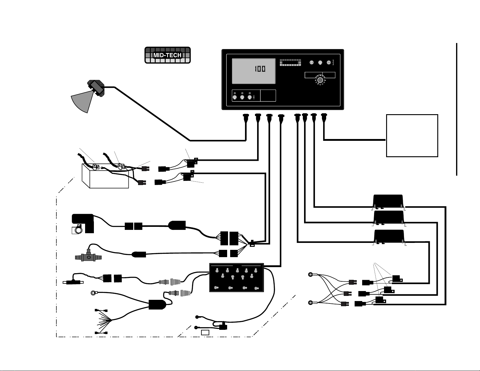
MIDWEST TECHNOLOGIES INC.
2733 East Ash Street
Springfield IL - (217) 753-8424
www.mid-tech.com
D5 - ROADSIDE SYSTEM DIAGRAM W/MID-TECH SWITCHBOX
RATE
CHEMICAL APPLICATORS
12
TASC-6000, 6300, 6600
ON OPERATE INC.
Flow
3
Gal./
Alt.Rate
ON
OFF
-Ac
.
TASC-6300
TOTAL APPLICATION
SPRAYER CONTROL
MIDWEST TECHNOLOGIES, INC.
MID-TECH
®
SET- UP
OFF
CHEMICALS CARRIER
%Rate
Chem. Rate
Appl. Rate
Chem. Applied
1234567 89
BOOMS
Area
Speed
Scan
DISPLAY SELECTOR
Total Applied
Width
Distance
Prime
Test
Speed
DEC.
TASC-6300 CONSOLE
or
TASC-6600 CONSOLE
D-9
Ground Speed Sensor
120-0000-KIT
Black
Vehicle Battery
(12 Volts)
Flow Control Valve
879-xxxx
Flow Meter
(120-xxxx)
Flowsensor
120-0004 or
120-0005
Frame
Ground
1
B
O
O
M
S
9
Red
Fuse,(5 amp)
Battery Cable
(45-05037)
+
Valve Driver Cable
(405-0143)
Flowmeter Interface Cable
(405-0044)
(404-0009)
Extension Cable
(404-0037)
9 Boom Sense
Cable
Battery
Power Cable
(401-0010)
Fuse,(10 amp)
Flow Control Cable
(404-0022)
BOOMS
MIDWEST TECHNOLOGIES, INC.
MASTER
GROUND SPEED
OFF - ON
OVERRIDE
ON "B"
OFF
(405-0088)
Boom Control
Switchbox
Caution
Connect To
+12v Only
Printer Module
(Optional)
Data Link
(Optional)
405-0069-96V
Chemical Injection Pumps
Pump Control
Cables
Pump Power
Cables
Pos.
Fuse,(15 amp)
Battery Cable
(401-0011)
SPRAY MODE
WIDTH
SPRAY MODE
AUTO
NORMAL - HANDGUN
NORMAL - HANDGUN
"C"
Connect
Direct to
BATTERY
Neg.
Roadside Wiring
98-05010
Rev. - 1
with
Mid-Tech Switchbox
Page 78

98-05010
Rev. - 1
TASC-6000, 6300, 6600
This page purposely left blank
D-10
 Loading...