

Page 1
MID-TECH
MIDWEST TECHNOLOGIES, INC.
TASC 6200/6500
TOTAL APPLICATION
CONTROL SYSTEM
USER GUIDE
PN - 98-05019
Rev - 1
CE & STANDARD VERSION
®
Flow
RATE
TASC-6500
CHEMICAL APPLICATORS
123
-Ac
.
Gal./
L
MID-TECH
MIDWEST TECHNOLOGIES, INC.
Alt.Rate
ON
C
OFF
ON OPERATE INC.
OFF SET- UP DEC.
RATE CONTROL CHANNELS
L & CHEMICALS CARRIER
%Rate
Appl. Rate
Appl. Rate
Vol. Applied
Speed
123456789
BOOMS
Area
Scan
Test
Speed
DISPLAY SELECTOR
Vol. Applied
Distance
Fan RPM
Width
Midwest Technologies, Inc. of Illinois
Springfield, IL 62703
I
Page 2

TASC 6200/6500
98-05019
Rev- 1
CHANGES
DATE REVISION # DESCRIPTION SW VERSION
05/15/00 1 New Manual - CE Console 2.62
Mid-T ech, Auto-Range, & T ASC ar e all registered trademarks of Midwest Technologies, Inc.
CE & STANDARD VERSION
Page 3

TASC 6200/6500
98-05019
Rev- 1
TABLE OF CONTENTS
TABLE OF CONTENTS .................................................................................................................................................. III
INTRODUCING TASC FOR THE NEW GENERATION APPLICATORS .............................................................. 1-1
1.0 SWITCHES AND CONTROLS ............................................................................................................................... 1-2
1.1 POWER SWITCH .............................................................................................................................................. 1-2
1.2MODE SELECTOR " OPERATE/SET-UP " SWITCH ................................................................................... 1-2
1.3 THE INC/DEC SWITCH................................................................................................................................... 1-2
1.4 THE DISPLAY SELECTOR SWITCH ............................................................................................................1-2
1.4.1 DISPLAY SELECTOR FUNCTIONS-OPERATE MODE.................................................................. 1-3
1.4.2 DISPLAY SELECTOR FUNCTIONS-SET-UP MODE....................................................................... 1-4
1.5 BOOM SECTION "ON/OFF" INDICATORS ................................................................................................. 1-5
1.6 FLOW CONTROL CHANNELS, PRODUCT SWITCHES.......................................................................... 1-5
1.7 CHEMICAL APPLICATOR CHANNELS, PRODUCT SWITCHES (TASC 6500 only) .......................... 1-5
1.8 BOOM CONTROL SWITCHES....................................................................................................................... 1-5
1.9 GROUND SPEED OVERRIDE SWITCH ....................................................................................................... 1-6
1.10 STATUS SWITCH ........................................................................................................................................... 1-6
2.0 CALIBRATION AND SET UP ............................................................................................................................... 2-1
2.1 U.S. OR METRIC UNITS ................................................................................................................................ 2-1
2.1.1 UNITS FOR EACH FUNCTION DISPLAYED POSITION (LIQUID APPLICATION) ................ 2-1
2.1.2 UNITS FOR EACH FUNCTION DISPLAYED POSITION (GRANULAR APPLICATION)........ 2-1
2.1.3 CHANGING UNITS............................................................................................................................... 2-1
2.2 SETTING CHANNEL 1, 2, 3 DRIVE METHOD (TASC 6500 ONLY) ...................................................... 2-1
2.3 SETTING THE SPLIT DRIVE OPTION ....................................................................................................... 2-2
2.4 SETTING APPLICATION RATES ................................................................................................................. 2-3
2.4.1 SETTING C CHANNEL APPLICATION RATE ................................................................................. 2-3
2.4.2 SETTING C CHANNEL PRODUCT DENSITY................................................................................. 2-3
2.4.3 SETTING ALL OTHER APPLICATION RATES ............................................................................... 2-3
2.4.4 SETTING PRODUCT DENSITY, CHANNELS 1, 2, 3 and L ........................................................... 2-4
2.5 SETTING THE % RATE CHANGE................................................................................................................ 2-4
2.6 SETTING THE HOLD OR CLOSE RESPONSE OF CHANNEL C, L, 1, 2, & 3 CONTROL VALVES 2-4
2.7 SETTING THE GROUND SPEED OVERRIDE SPEED (GSO) ................................................................. 2-5
2.8 SETTING THE TEST SPEED VALUE .......................................................................................................... 2-5
2.9 SETTING BOOM WIDTHS ............................................................................................................................ 2-6
2.10 DISTANCE CALIBRATION ......................................................................................................................... 2-6
2.10.1 INITIAL CALIBRATION SETTINGS ............................................................................................... 2-6
2.10.2 DISTANCE CALIBRATION PROCEDURE ..................................................................................... 2-6
2.11 CALIBRATION OF CHANNEL C ................................................................................................................ 2-7
2.12 CALIBRATING THE L CHANNEL ............................................................................................................. 2-8
2.13 CALIBRATING PRODUCTS 1,2 AND 3 (TASC 6500 ONLY) ............................................................. 2-10
2.13.1 CALIBRATING MID-TECH® INJECTION PUMPS .................................................................... 2-10
2.13.2 CALIBRATING GRANULAR BIN APPLICATORS ...................................................................... 2-11
2.14 SETTING AUTO POWER DOWN TIME ................................................................................................. 2-12
2.15 OPERATING UNDER EXTERNAL RATE COMMANDS ...................................................................... 2-13
III
CE & STANDARD VERSION
Page 4

98-0501
TASC 6200/6500
Rev- 1
3.0 OPERATION............................................................................................................................................................. 3-1
3.1 NORMAL START UP AND OPERATION .................................................................................................... 3-1
3.1.1 CALIBRATION NUMBERS AND CONSTANTS ............................................................................... 3-1
3.1.2 APPLICATION RATES ......................................................................................................................... 3-1
3.1.3 ACCUMULATED AREA....................................................................................................................... 3-1
3.1.4 ACCUMULATED AMOUNTS ............................................................................................................. 3-1
3.1.5 OPERATE................................................................................................................................................ 3-1
3.1.6 CHECK THE VEHICLE ........................................................................................................................ 3-1
3.1.7 START APPLYING ................................................................................................................................ 3-1
3.1.8 STOP APPLYING.................................................................................................................................. 3-2
3.2 GROUND SPEED OVERRIDE (GSO)........................................................................................................... 3-2
3.3 CHANGING ACTIVE BOOM SECTIONS.................................................................................................... 3-2
3.4 CHANGING APPLICATION CHANNELS ................................................................................................... 3-2
3.5 CHANGING APPLICATIO RATES ON THE GO ........................................................................................ 3-2
3.5.1 ALTERNATE APPLICATION RATES FOR EACH CHANNEL....................................................... 3-2
3.5.2 CHANGING THE PERCENT RATE ON THE CARRIE CHANNEL ONLY ................................. 3-3
3.5.3 CHANGING THE PERCENT RATE OF CHANNELS 1, 2, 3 AND L SIMULTANEOUSLY ....... 3-3
3.5.4 CHANGING THE PERCENT RATE OF ALL CHANNELS SIMULTANEOUSLY........................ 3-3
3.6 MANUAL OVERRIDE OF CONTROL VALVE ........................................................................................... 3-4
3.6.1 OVERRIDE CHANNEL C CONTROL ................................................................................................ 3-4
3.6.2 OVERRIDE CHANNEL L, 1, 2, & 3 ................................................................................................... 3-4
3.7 SETTING TEST SPEED .................................................................................................................................. 3-4
4.0 MAINTENANCE ...................................................................................................................................................... 4-1
4.1 FLUSHING AND CLEANING ......................................................................................................................... 4-1
4.3 GROUND SPEED SENSOR ............................................................................................................................. 4-2
4.3.1 WHEEL SENSOR................................................................................................................................... 4-2
4.3.2 RADAR SENSOR .................................................................................................................................... 4-2
4.4 FLOW METER................................................................................................................................................... 4-2
4.5 HYDRAULIC FLOW CONTROL VALVES ................................................................................................... 4-2
4.6 LIQUID FLOW CONTROL VALVES ............................................................................................................. 4-2
4.7 ROTATIONAL SENSORS ................................................................................................................................ 4-3
4.8 MID-TECH PERISTALTIC LIQUID INJECTION PUMPS (TASC 6500 ONLY) ...................................... 4-3
4.8.1 DAILY...................................................................................................................................................... 4-3
4.8.2 WEEKLY .................................................................................................................................................. 4-3
4.8.3 SEASONAL.............................................................................................................................................. 4-3
4.8.4 PERIODIC ................................................................................................................................................ 4-3
4.9 OTHER INJECTION PUMPS (TASC 6500 ONLY)....................................................................................... 4-3
4.9.1 SEASONAL.............................................................................................................................................. 4-4
4.9.2 PERIODIC ................................................................................................................................................ 4-4
4.10 WIRING HARNESS ........................................................................................................................................ 4-4
5.0 TASC ERROR MESSAGES, COMMON CONDITIONS AND SOLUTIONS .................................................. 5-1
6.0 - EMERGENCY OPERATIONS .............................................................................................................................. 6-1
6.1 - GROUND SPEED SENSOR FAILURE ........................................................................................................ 6-1
6.2 - FLOW CONTROL VALVE FAILURE (LIQUID APPLICATOR).............................................................. 6-1
6.3 - FLOW METER FAILURE (LIQUID APPLICATOR) ................................................................................. 6-2
6.4 - APPLICATION RATE SENSOR FAILURE (GRANULAR APPLICATION) ........................................... 6-3
A.0 APPENDIX ............................................................................................................................................................. A-1
A.1 TASC 6500 SYSTEM DRAWING................................................................................................................. A-2
A.2 TASC 6500 SYSTEM DIAGRAM................................................................................................................. A-3
A.4 FUSES AND POWER CONNECTIONS ...................................................................................................... A-4
A.5 USEFUL FORMULAS.................................................................................................................................... A-5
A.6 FLUID OUNCES CONVERSION TABLE ................................................................................................... A-6
A.7 METRIC / U.S. UNIT CONVERSION CHART .......................................................................................... A-7
CE & STANDARD VERSION
IV
Page 5

TASC 6200/6500
MIDWEST TECHNOLOGIES, INC.
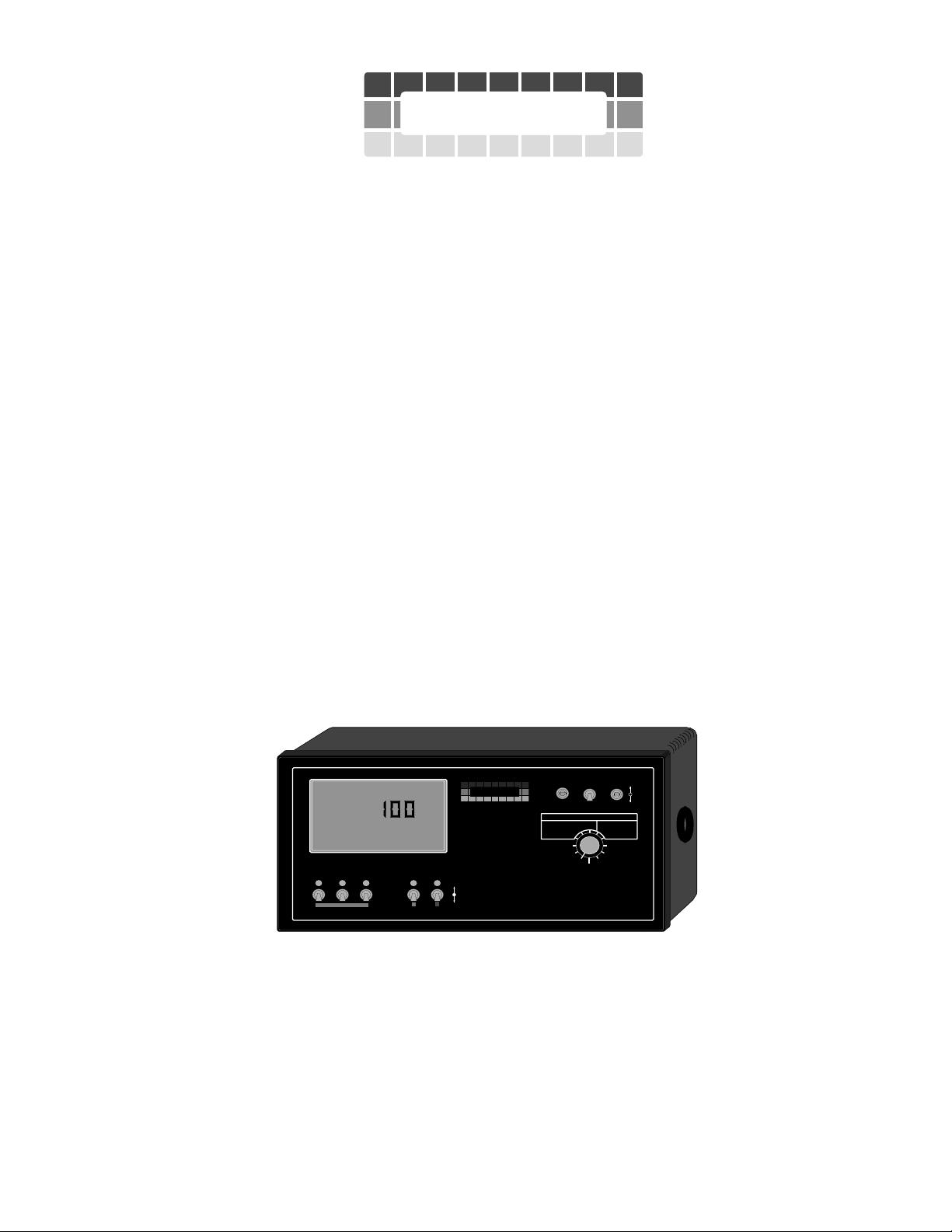
TASC 6 200/6500 S PREADER C ONTROL
®
Flow
RATE
TASC-6500
CHEMICAL APPLICATORS
123
-Ac
.
Gal./
L
MID-TECH
MIDWEST TECHNOLOGIES, INC.
Alt.Rate
ON
C
OFF
ON OPERATE INC.
OFF SET- UP DEC.
RATE CONTROL CHANNELS
L & CHEMICALS CARRIER
%Rate
Appl. Rate
Appl. Rate
Vol. Applied
Speed
123456789
BOOMS
Area
Scan
Test
Speed
DISPLAY SELECTOR
Vol. Applied
Distance
Fan RPM
Width
98-05019
Rev- 1
INTRODUCING TASC FOR THE NEW GENERATION APPLICATORS
The TASC 6500 is a five channel controller. Two channels are designed to operate positional control valves, such as
hydraulic or liquid flow control valves, while the other three channels are designed to operate either positional
control valves or DC motors. This gives the MID-TECH TASC 6500 the flexibility to control almost any mobile
applicator using a single console.
All five channels control spread or spray rates in relation to ground speed and width. Each channel has two programmable rates or can be changed by a percentage amount "ON THE GO". The TASC 6500 is easy to calibrate and
operate and incorporates many self check features to help the operator keep the system running at peak performance.
The TASC 6200 is a simpler version of the TASC 6500 console. The TASC 6200 has two channels designed to
operate positional control valves only.
1-1
CE & S
TANDARD VERSION
Page 6
98-05019
TASC 6200/6500
Rev- 1
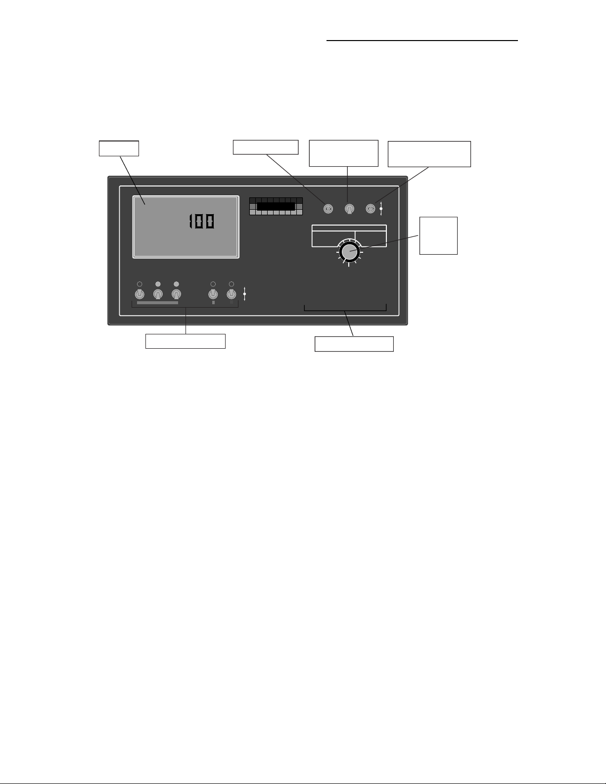
1.0 SWITCHES AND CONTROLS
The figure below shows the switches and displays on the TASC 6500 Control Console. The TASC 6200 Console is
the same with the exception of the Chemical Applicator Product Switches.
Display
Flow
RATE
TASC-6500
CHEMICAL APPLICATORS
123
Product Switches
Gal./
Power Switch
-Ac
.
C
L
MID-TECH
MIDWEST TECHNOLOGIES, INC.
Alt.Rate
ON
OFF
Mode Selector
Switch
®
ON OPERATE INC.
OFF SET- UP DEC.
RATE CONTROL CHANNELS
L & CHEMICALS CARRIER
%Rate
Appl. Rate
Vol. Applied
Area
Speed
123456789
BOOMS
Appl. Rate
Vol. Applied
Width
Distance
Fan RPM
Scan
Test
Speed
DISPLAY SELECTOR
Boom Indicators
Increase/Decrease
switch
Display
Selector
Switch
1.1 POWER SWITCH
The power switch controls power to the console. The console has an "Auto Power Down" feature which powers the
console off after an operator selectable time (default is 30 min) has elapsed. The console has a nonvolatile memory
so it "remembers" the constants and data previously entered, even if the power is removed.
NOTE: The “Auto Power Down Feature is only available on the CE version of the console (CE designation label on
back of console).
1.2 MODE SELECTOR " OPERATE/SET-UP " SWITCH
The mode selector switch selects between the operate mode and the set-up mode. This switch must be in the operate
position for the system to control the chemical application process. The set-up position is used for entering information into the console. Anytime an incorrect switch setting is selected, an "Err" message will appear on the display.
1.3 THE INC/DEC SWITCH
The INC/DEC switch is used to change values appearing on the display. This switch is also used to zero accumulated data and to select special programming modes for the console.
1.4 THE DISPLAY SELECTOR SWITCH
The display selector switch is used to select information displayed and console functions to be adjusted. Each
position will display different information depending on the mode selector switch setting. The following pages will
explain the information displayed and functions available for each display selector switch setting. Anytime an
incorrect switch setting is selected, an "Err" message will appear.
CE & STANDARD VERSION
1-2
Page 7

TASC 6200/6500
ON
OFF
Alt.-
Rate
123456789
BOOMS
MID-TECH
MIDWEST TECHNOLOGIES, INC.
%Rate
DISPLAY SELECTOR
Speed
Area
Width
Distance
Vol. Applied
Test
Speed
Fan RPM
Vol. Applied
Appl. Rate
Appl. Rate
Scan
RATE CONTROL CHANNELS
L & CHEMICALS CARRIER
.
-Ac
al./
®
L
C
98-05019
Rev- 1
1.4.1 DISPLAY SELECTOR FUNCTIONS-OPERATE MODE
OPERATE
®
OPERATE
ON
SET- UP
OFF
RATE CONTROL CHANNELS
%Rate
Appl. Rate
Area
Speed
Scan
Test
Speed
DISPLAY SELECTOR
Appl. Rate
Vol. Applied
Width
Distance
Fan RPM
INC.
DEC.
Flow
RATE
.
Gal./
RATE CONTROL CHANNELS
TASC-6500
L & CHEMICALS CARRIER
CHEMICAL APPLICATORS
Vol. Applied
123
%Rate
Appl. Rate
L
Area
Speed
Scan
Test
Speed
DISPLAY SELECTOR
-Ac
MIDWEST TECHNOLOGIES, INC.
Alt.-
Rate
Appl. Rate
ON
Vol. Applied
C
OFF
Width
Distance
Fan RPM
MID-TECH
SET- UP
L & CHEMICALS CARRIER
Vol. Applied
123456789
BOOMS
SPEED: The current vehicle speed.
AREA: Accumulated Area.*
L & CHEMICALS - Vol. Appl.: The total amount of material actually discharged by channels 1, 2, 3, & L.
Units are not displayed. The display cycles through the active channels in sequence (all channels if none are turned
on).*
L & CHEMICALS - Appl. Rate: The target application rate, for channels 1, 2, 3, & L, when the ground speed
is zero or all booms are OFF. Once application has started, the actual application rate is displayed here. The display
cycles through the active channels in sequence (all channels if none are turned on).***
L & CHEMICALS - % RATE: The percent of programmed application rate at which all active channels (1, 2,
3, L, C) are operating. Alarm beeps and display flashes indicating abnormal operation. Switching to another position
cancels alarm and rate change.***
CARRIER APPL. RATE: Shows the target application rate, when the ground speed is zero or all booms are
OFF. Once application has started, the actual application rate is displayed here.***
CARRIER - VOL. APPLIED: The total volume discharged by the conveyor, as measured by the rate sensor.
Rounds to Tons (Metric Tons) after accumulating 19999 pounds (10,000 Kg).*
WIDTH: The active boom width in Feet (meters). Value depends on individual boom section lengths and which
sections are active.
DISTANCE: The total distance in feet (miles after 5,280 Ft.) or meters (kilometers after 1000 meters).*
FAN RPM: The current speed of the fans (spinners) in RPM
TEST SPEED: The speed the console uses for stationary tests. Use the INC/DEC switch to change this value.
(When this function is selected, and booms and applicators are turned on, the system applies as if it were actually
traveling at this speed.)**
SCAN: The display scans SPEED, AREA, L & CHEMICALS - VOL. APPLIED & APPL. RATE, CAR-
RIER - APPLICATION RATE & VOL. APPLIED, and FAN RPM
display holds at each position for approximately two seconds before advancing to the next.
(if FAN RPM Cal. # not set to zero). The
NOTES: * Totals can be zeroed in this mode.
** Values are programmable in this mode.
*** Values changeable by a % increase or decrease.
1-3
CE & S
TANDARD VERSION
Page 8

98-05019
ON
OFF
Alt.-
Rate
123456789
BOOMS
MID-TECH
MIDWEST TECHNOLOGIES, INC.
%Rate
DISPLAY SELECTOR
Speed
Area
Width
Distance
Vol. Applied
Test
Speed
Fan RPM
Vol. Applied
Appl. Rate
Appl. Rate
Scan
RATE CONTROL CHANNELS
L & CHEMICALS CARRIER
.
-Ac
./
L
C
TASC 6200/6500
Rev- 1
1.4.2 DISPLAY SELECTOR FUNCTIONS-SET-UP MODE
OPERATE
®
ON
Flow
RATE
.
Gal./
RATE CONTROL CHANNELS
TASC-6500
CHEMICAL APPLICATORS
L & CHEMICALS CARRIER
123
Vol. Applied
%Rate
Appl. Rate
L
Area
Speed
Scan
Test
Speed
DISPLAY SELECTOR
-Ac
MIDWEST TECHNOLOGIES, INC.
Alt.-
Rate
Appl. Rate
ON
C
OFF
Vol. Applied
Width
Distance
Fan RPM
MID-TECH
SET- UP
L & CHEMICALS CARRIER
Vol. Applied
123456789
BOOMS
SPEED: Ground Speed Override (GSO) Value. INC/DEC Switch changes.**
AREA: Total accumulated Area.
L & CHEMICALS - Vol. Appl.: Channel 1, 2, 3, or L Product switch "ON": Product Density. Channel 1, 2, 3,
or L Product switch "ALT-RATE": Cal. # for active channel. (Other channels, including C, must be off.) (Channel in
split drive: All booms with a programmed width must be on to view calibration number. Err is displayed until a
channel is selected.) Channel in non-peristaltic: Density. **
OPERATE
OFF
SET- UP
RATE CONTROL CHANNELS
%Rate
Appl. Rate
Area
Speed
Scan
Test
Speed
DISPLAY SELECTOR
Appl. Rate
Vol. Applied
Width
Distance
Fan RPM
INC.
DEC.
L & CHEMICALS - Appl. Rate: The target application rates for channels 1, 2, 3, & L. Each channel can be
set to different rates in the "ON" and "ALT-RATE" positions.**
L & CHEMICALS - % RATE: The percent of change in programmed application rate at which all five
channels are changed by each activation of the INC/DEC switch.**
CARRIER APPL. RATE: The target application rate for the C Channel. Different rates can be programmed
into the "ON" and "ALT-RATE" positions. Displays Err unless C Channel switch is on.**
CARRIER - VOL. APPLIED: C Channel Product switch - "ON": Product Density. C Channel Product switch
- Alt. Rate: Calibration number.**
WIDTH: Individual boom section widths in inches (meters). Display cycles through all sections unless one section
is turned on. Each section width can be set, using the INC/DEC Switch, as the desired section appears on the display,
or the switch for each section can be turned "ON" individually. Boom Section C is the "Test Boom Width" used for
pump calibration etc. (normally set to the total boom width).**
DISTANCE: The Distance Calibration Number.**
Fan RPM: The current Fan RPM Calibration number. Should be set to the number of pulses the fan sensor will
generate for each revolution of the fan. This Cal. # can be set to zero to remove the FAN RPM reading from the
"SCAN" feature.**
TEST SPEED: The current Test Speed.**
SCAN: The "All Booms OFF" Hold/Close response is set in this position.
NOTES: * Totals can be zeroed in this mode.
CE & STANDARD VERSION
** Values are programmable in this mode.
***Values changeable by a % increase or decrease.
1-4
Page 9

TASC 6200/6500
98-05019
Rev- 1
1.5 BOOM SECTION "ON/OFF" INDICATORS
The boom section on/off indicators show which boom sections have been selected. There is a maximum of nine
boom sections available. When a boom section is selected, its indicator light will light.
1.6 FLOW CONTROL CHANNELS, PRODUCT SWITCHES
Two channels on the TASC are designated as flow control channels only. Both are designed to operate positional
control valves. Channel C is normally used to control the spreader conveyor using a positional hydraulic control
valve. Channel L is normally used to control a liquid application using either a positional flow control valve or a
positional hydraulic control valve. This could be either a wet boom applicator or a liquid impregnation applicator.
Both channels can be preset for a standard rate and an alternate rate. When the switch is turned "ON", its indicator
lamp lights to show the applicator has been selected at its standard rate. When "Alt.-Rate" is selected, the indicator
lamp flashes to indicate a non-standard application rate.
1.7 CHEMICAL APPLICATOR CHANNELS, PRODUCT SWITCHES (TASC 6500 only)
Channels 1, 2, or 3, operating in Peristaltic or Non-Peristaltic modes, require that Channel L or C be ON in order for
them to operate.
Channels 1,2 and 3, are used to control up to three separate chemical applicators. When operating in peristaltic or
non-peristaltic mode, these three channels control the speed of a motor by varying the drive signal to that motor.
Typical installations include the control of liquid injection pumps on a wet boom or granular co-applicators with a
dry conveyor.
When channels 1, 2, or 3 are running in Flow Mode they operate like the L and C channels and can be used to
control a positional control valve.
All three channels can be set for a standard or alternate application rate. When the switch is turned "ON", its indicator lamp lights to show the applicator is selected at its standard rate. When "Alt.-Rate" is selected, the indicator lamp
flashes to indicate a non-standard application.
1.8 BOOM CONTROL SWITCHES
Externally mounted boom control switches are necessary for the proper operation of a TASC system. MIDWEST
TECHNOLOGIES can provide several optional configurations for these switches to meet differing needs. The
console must receive 12 VDC on the boom status line whenever a boom is turned ON.
A boom master switch is a recommended feature. It can be used to turn on or off all selected booms simultaneously.
MASTER
ON
OFF
BOOM
LEFT RIGHT
BOTH
Ground Speed
Override
OFF
AUTO
MID-TECH
MIDWEST TECHNOLOGIES, INC.
WET BOOMS
ON
OFF
Mid-Tech 105-0025 Boom Control Switch Box used on some applicators
Wet Boom
PUMP
AUTO
MANUAL
1-5
CE & S
TANDARD VERSION
Page 10

98-05019
TASC 6200/6500
Rev- 1
1.9 GROUND SPEED OVERRIDE SWITCH
An optional ground speed override (GSO) switch can be used to temporarily operate the system using a pre-selected
minimum speed. GSO brings the applicator on line quickly when starting from a dead stop and can also be used to
maintain a minimum application rate when maneuvering the vehicle at very low ground speeds (Actual application
rate, based on actual ground speed, is displayed). Finally, GSO can be used to empty the applicator from the cab
while the vehicle is stopped (zero ground speed) (Display reads "- FLO").
TASC operates normally, when traveling above GSO speed or when the GSO switch is OFF. When the GSO switch
is closed (ON), and the actual ground speed is less then the minimum speed preset in the console, the console
automatically selects the GSO speed value to control application rates. As soon as the switch is turned OFF, or the
actual ground speed increases above the GSO speed, TASC controls application rates based on the actual ground
speed.
BOOM CONTROL SWITCHES
MASTER
ONOFF
MID-TECH
MIDWEST TECHNOLOGIES, INC.
GSO
®
AUTO
OFF
Mid-Tech 405-0075 Single Conveyor Switchbox
with Master Switch and Off/Auto/GSO Switch
If your GSO Switch is labeled "OFF / AUTO / GSO", then you must have the switch in AUTO (console controls to
ground speed only) or GSO position (console controls to GSO speed if ground speed is below GSO speed). The OFF
position operates the same as turning the STATUS switch off. (See paragraph 1.10 below)
CAUTION: When traveling at a speed slower than the GSO speed setting, this feature causes the product to
be applied at a rate consistent with the GSO speed, rather than the true ground speed. Caution must be
exercised when operating in this mode as serious over application can occur, if not used properly. When GSO
is being used, and the true ground speed is less than the pre-selected “GSO” speed, the console sounds an
alarm and the display flashes a “Too Slow” message to warn the operator of possible over application.
1.10 STATUS SWITCH
An externally mounted status switch can be used to turn TASC on and off. As long as this switch is ON (closed)
TASC operates normally. Whenever the switch is OFF (open), TASC turns off the applicator channels.
The intent of the status switch is to control TASC through the normal operation of the vehicle. The status switch may
sense the ON/OFF condition of the main applicator or it may sense an implement UP/DOWN condition. Use of the
status switch can ease the operator work load.
CE & STANDARD VERSION
1-6
Page 11

TASC 6200/6500
98-05019
Rev- 1
2.0 CALIBRATION AND SET UP
NOTE: PLEASE READ THROUGH THE FOLLOWING SECTIONS COMPLETELY BEFORE YOU BEGIN CALIBRATION!
In order to control accurately, the TASC console requires certain information about your system, such as application
rates, boom widths, test speed, etc.. Next, the rate sensor and ground speed sensor must be calibrated.
2.1 U.S. OR METRIC UNITS
The control console is capable of displaying two different units of measure, US and Metric.
2.1.1 UNITS FOR EACH FUNCTION DISPLAYED POSITION (LIQUID APPLICATION) FUNCTION U.S. METRIC
Speed Miles/Hour (MPH)* Kilometers/Hour (KPH)*
Area Acres (-Ac)* Hectares (-Ha)*
Chem. Vol. Applied Ounces-U.S. Gallons (TOTAL)* Liters (TOTAL)*
Chem. Appl. RateOunces/Acre (RATE -Ac)* Liters/Acre (RATE -Ha)*
Carrier Appl. Rate U.S. Gallons/Acre (Flow RATE -Ac)* Liters/Hectare (Flow RATE -Ha)*
Carrier Vol. Applied U.S. Gallons (TOTAL Flow)* Liters (TOTAL Flow)*
Width Inches-Feet (TOTAL Boom Ft.)* Meters (TOTAL Boom Meters)*
Distance Feet-Miles (Dist. Ft.)*** Meters-Kilometers (Dist. Meters)***
2.1.2 UNITS FOR EACH FUNCTION DISPLAYED POSITION (GRANULAR APPLICATION) FUNCTION U.S. METRIC
Speed Miles/Hour (MPH)* Kilometers/Hour (KPH)**
Area Acres (-Ac)* Hectares (-Ha)*
Chem. Vol. Applied Pounds (TOTAL)* Kilograms (TOTAL)*
Chem. Appl. Ratepounds/Acre (RATE -Ac) Kilograms/Hectare (RATE -Ha)*
Carrier Appl. Rate Pounds/Acre Kilograms/Hectare
(Flow RATE -Ac)* (Flow RATE -Ha)*
Carrier Vol. Applied Pounds-Tons (TOTAL Flow)* Kilograms-Metric Tons (TOTAL Flow)*
Width Inches-Feet (TOTAL Boom Ft.)* Meters (TOTAL Boom Meters)*
Distance Feet-Miles (Dist. Ft.)*** Meters-Kilometers (Dist. Meters)***
Product Density Pounds/Cubic Ft. (Cu. Ft.)* Kilograms/Tenths of Meter3 (Meters C)*
* Items in parenthesis are the abbreviations that appear on the screen.
** No units displayed
*** No units displayed after roll over of feet to miles or meters to kilometers
2.1.3 CHANGING UNITS
To change units, set the Mode Switch to “OPERATE” and the Display Selector to “SPEED”. The current speed units
are displayed (MPH or KPH). Holding the INC/DEC switch down for about 10 sec. causes the display to alternate
between U.S. and Metric modes. Release the DEC Switch when the desired mode is displayed.
2.2 SETTING CHANNEL 1, 2, 3 DRIVE METHOD (TASC 6500 ONLY)
The TASC 6500 Chemical Applicator channels (1, 2, 3) can use three different drive methods, depending on the type
of equipment being controlled by the individual channel. "Peristaltic Drive" is used for peristaltic injection pumps.
"Non-Peristaltic Drive" can be used for a granular bin motor. "Flow Mode" is used to control a positional control
valve, such as a hydraulic flow control valve. You must use the appropriate drive method for proper operation.
A. Use the following switch settings to select the desired drive method (You should have to do this only once
unless you change your equipment configuration.).
2-1
CE & STANDARD VERSION
Page 12

98-05019
TASC 6200/6500
Rev- 1
Power OFF
Mode selector SET-UP
Display selector DISTANCE
B. Turn the rate selector switches, for any channels (1,2 or 3) that you want to set to non-peristaltic to "ON".
C. Turn the rate selector switches, for any channels (1,2 or 3) that you want to set to FLOW MODE, to
"ALTERNATE RATE".
Any channels left "OFF" will be set to the peristaltic mode.
D. Hold the INC/DEC switch down while turning on the TASC power. After completing the start up routine,
the display settles on a series of o's, -'s, and F's. The o's correspond to the channels that are set to nonperistaltic drive, -'s indicate peristaltic channels, and F's indicate channels that are in Flow Mode.
F o -
Indicates channel 1 is set to "Flow Mode", 2 is set to non-peristaltic drive and channel 3 is set for peristaltic.
E. If it is ever necessary to reset the channel configuration, simply repeat the above procedure selecting the
desired switch configuration.
F. Whenever the TASC power is turned ON, the console momentarily displays the drive status of the three
chemical applicator channels (unless all three channels are in peristaltic mode).
2.3 SETTING THE SPLIT DRIVE OPTION
Each TASC control channel (1, 2, 3, L, C) has the option of operating in either standard or split drive. Split drive is
used to control a channel where changes in boom settings do not affect the drive speed of the controlled shaft or
motor. An example is a split conveyor with two separate drive motors feeding a two boom granular air delivery
applicator.
If you can't decide whether to use split or standard drive on a particular control channel, contact your MID-TECH
supplier, or the factory, for help.
A. Use the following switch settings to change from standard to split drive (you should have to do this only
once).
Power OFF
Mode selector SET-UP
Display selector L & CHEMICALS, APPL. RATE
Booms and pumps OFF
Hold the INC switch UP while turning the power on
The display will show an Err message when power up is completed.
B. Turn the desired product switch ON and the display shows which drive configuration is set (Stnrd for
standard or SPLit for split).
C. Select the desired configuration by holding the INC switch UP. The display alternates between standard and
split. The selection being displayed as you release the INC switch is locked in. (If the channel is in peristaltic mode the only choice is Stnrd.)
CE & S
D. Repeat steps B and C for each channel independently.
E. Turn the display selector switch or move the Mode switch to OPERATE to exit this function.
TANDARD VERSION
2-2
Page 13

TASC 6200/6500
98-05019
Rev- 1
NOTE: Whenever a channel is set to the split drive
option, all booms, to be used, must be turned "ON"
and have widths entered before the calibration number can be changed. If a boom position will not be used
it must be set to 0.
2.4 SETTING APPLICATION RATES
Each TASC channel can maintain a constant, preset application rate. To do this, the operator must enter the desired
application rates.
2.4.1 SETTING C CHANNEL APPLICATION RATE
A. Set the console switches to the following positions:
Power ON
Mode Selector SET-UP
Channel C Product Switch ON (CENTER)
Display Selector CARRIER, APPL. RATE
The display shows the current channel C application rate.
B. Use the INC/DEC switch to set the value displayed to the new desired rate.
C. Repeat with the Channel C Rate set to ALT-RATE. This establishes an alternate rate.
2.4.2 SETTING C CHANNEL PRODUCT DENSITY
TASC needs to know the product density in order to control the application rate of the product accurately. Product
density is entered in pounds per foot3 (kilograms/tenths of meters3).
A. Set the console switches to the following positions:
Power ON
Mode Selector SET-UP
Channel C Product Switch ON
Display Selector CARRIER, VOL. APPLIED
The display shows the current channel C product density.
B. Use the INC/DEC switch to set the value displayed to the new desired rate.
C. NOTE: If channel C is being used as a liquid control channel, set the Product Density to 1.0
2.4.3 SETTING ALL OTHER APPLICATION RATES
A. Set the console switches to the following positions:
Power ON
Mode Selector SET-UP
Display Selector L & CHEMICALS, APPL. RATE
Channel 1,2,3 or L Product Switch ON (CENTER)
The display shows the current standard application rates for each channel.
2-3
CE & STANDARD VERSION
Page 14

98-05019
TASC 6200/6500
Rev- 1
B. Use the INC/DEC switch to set the desired rate. Example, 64.0 for 64 Fluid Oz. (2 qts.) per acre.
NOTE: The Mode Switch must be moved back to OPERATE for the new rate to be registered by the console.
C. Repeat with the Product Switch set to ALT-RATE. This will establish an alternate rate.
D. Program the remaining channels, one at a time, using the procedure outlined in steps A through C above.
NOTE: Set the rates for granular co-applicators in Lbs/acre (Kg./Ha.). Set
the rates for chemical injection pumps in oz./acre (L/Ha.). Set the rates for
liquid channels in gallons per acre (L/Ha.).
2.4.4 SETTING PRODUCT DENSITY, CHANNELS 1, 2, 3 and L
In order to control accurately, the TASC controller requires a product density value for channel L (and for channels
1, 2, and 3 when they are set to the non-peristaltic or Flow mode). It is important to ensure the density is set correctly
for the material you are applying.
A. Set the console switches to the following positions:
Power ON
Mode Selector SET-UP
Display Selector L & CHEMICALS, VOL. APPLIED
Channel 1, 2, 3 or L Product SwitchON (CENTER) (one at a time)
B. Use the INC/DEC switch to set the density. Example cu25.0 for 25.0 pounds per cubic foot
(kg./0.1m3).
NOTE: If the channel is being used to control a liquid pump in the non-peristaltic or flow mode, set the density
to 1.0.
C. If no channel is selected or, if more than one channel is selected, the display will read Err.
2.5 SETTING THE % RATE CHANGE
This feature allows the operator to change application rates ON THE GO. Rates are changed with a simple actuation
of the INC/DEC switch. The amount of change each switch actuation makes is the value set into the % RATE/SETUP position, (e.g. 20 =20% change in the target rate). For example, if the application rate (on channel C) is set to 400
Lb per acre, a single actuation of the INC switch will cause the rate to go to 480 Lb per acre (400 + 20% = 480).
A. Set the Console switches to the following positions;
Power ON
Mode Selector SET-UP
Display Selector % RATE
The display shows the current % change value.
B. Use the INC/DEC switch to set this number to the desired % change.
2.6 SETTING THE HOLD OR CLOSE RESPONSE OF CHANNEL C, L, 1, 2, & 3 CONTROL
VALVES
(Channels 1, 2, 3 in Flow Mode Only)
The operator has the option of selecting the response of the control valve, associated with each channel, to the
"Booms OFF" condition. When the valve response CLOSE is selected, TASC closes the control valve when the
booms are shut OFF. When the HOLD response is selected, TASC holds the valve in its current position when the
CE & S
TANDARD VERSION
2-4
Page 15

TASC 6200/6500
98-05019
Rev- 1
booms are turned OFF. HOLD is useful in maintaining pressure to the boom shut-off valves on a liquid control
channel.
To check or change the valve response, use the following procedure:
A. Set the console switches as shown:
Power ON
Mode selector SET-UP
Display selector SCAN
Booms OFF
Product L, C, 1, 2, or 3 ON (CENTER) (one at a time)
The display will read HOLD or CLOSE. The response can be changed using the INC switch. (Hold the INC
switch up until the display changes. The response shown on the display when the switch is released is the
selected response for that channel.) There is no selectable response when the channel is in peristaltic or nonperistaltic mode.
B. If no channel is selected or, if more than one channel is selected, the display will read Err.
2.7 SETTING THE GROUND SPEED OVERRIDE SPEED (GSO)
The GSO function generates an operator selectable speed signal which TASC will use whenever the GSO switch is
turned on and actual ground speed is less than the selected setting.
A. Use the following switch settings to enter the desired GSO speed.
Power ON
Mode selector SET-UP
Display selector SPEED
B. Use the INC/DEC switch to set the desired speed.
C. The GSO speed will be used by TASC whenever the GSO switch is ON (closed) and the actual ground
speed is less than the GSO speed selected.
NOTE: If you do not have a GSO switch, the only way to turn GSO off is to set the GSO speed to zero.
CAUTION: When traveling at a speed slower than the GSO speed setting, this feature causes the product to
be applied at a rate consistent with the GSO speed, rather than the true ground speed. Caution must be
exercised when operating in this mode as serious over application can occur if not used properly. When GSO
is being used, and the true ground speed is less than the pre-selected “GSO” speed, the console sounds an
alarm and the display flashes a “Too Slow” message to warn the operator of possible over application.
2.8 SETTING THE TEST SPEED VALUE
The Test Speed function generates an operator selectable speed signal which TASC will use whenever the Display
Selector Switch is set to the Test Speed position.
A. Use the following switch settings to enter the desired test speed.
Power ON
Mode selector SET-UP or OPERATE
Display selector TEST SPEED
B. Use the INC/DEC switch to set the desired speed.
2-5
CE & STANDARD VERSION
Page 16

98-05019
TASC 6200/6500
Rev- 1
2.9 SETTING BOOM WIDTHS
TASC automatically compensates for changes in the swath width, caused by changing active boom sections. To do
this, it is necessary for the operator to define the boom widths using the following procedure.
A. Set the Console switches to the following positions;
Power ON
Mode Selector SET-UP
Display Selector WIDTH
All Boom Switches (external) OFF
The display cycles through each boom position and displays its current width.
B. As each boom position appears on the display, use the INC/DEC switch to set the display to the number of
inches (meters) covered by that boom section.
C. Set all unused boom sections (up to a total of nine) to a width of zero “0” inches (meters). This ensures that
an accidental boom switch ON signal does not affect application rates.
D. Finally, let the boom width display cycle through the boom sections until it shows Boom C. As the width of
C is displayed, it can also be changed with the INC/DEC switch. This value is used by the console to control
the operating rate for each channel during calibration operations where the boom switches are normally
OFF. This value is normally set to the total operating width of the entire applicator, in inches (meters).
E. When the boom widths are set turn all the live booms ON and return to the OPERATE mode, the new total
boom width is displayed in feet (meters). If this does not agree with your total boom width, check the
individual boom widths again, (steps B and C).
2.10 DISTANCE CALIBRATION
The ground speed sensor must be calibrated to ensure accurate application rates. This calibration should be periodically checked, especially if the sensor has been moved or the tires have been changed.
2.10.1 INITIAL CALIBRATION SETTINGS
The following values will be close. Use them for the initial settings so you get an initial reading of distance during
the calibration procedure.
NOTE: IT IS IMPORTANT TO FIELD CALIBRATE THE GROUND SPEED SENSOR TO INSURE OPTIMUM
ACCURACY.
MID-TECH COMPACT RADAR - 779 DICKEY- john RADAR - 1000
WHEEL SENSOR - 3500 SPEEDOMETER SENSOR - 3500
A. Use the following switch settings to enter the initial distance calibration number.
Power ON
Mode selector SET-UP
Display selector DISTANCE
B. The INC/DEC switch is used to set the initial number.
2.10.2 DISTANCE CALIBRATION PROCEDURE
A. Fill the machine 1/2 full of product to approximate average load conditions.
B. Measure a known distance of 400 feet (150 meters) or more along a field or roadway. It should be in an easy
CE & S
TANDARD VERSION
2-6
Page 17

TASC 6200/6500
place to maneuver the vehicle. The longer the distance, the more accurate the test.
C. Drive to the starting point and STOP. Make sure all booms are OFF. Turn ON the TASC power switch.
D. Turn the display selector to DISTANCE and put the mode selector in SET-UP. The TASC displays the
current distance calibration number. Record this number for reference.
E. Put the mode selector switch to the OPERATE position and use the DEC switch to set the accumulated
distance reading to ZERO. (If the console shows a distance being accumulated while the vehicle is station-
ary, the radar is vibrating. Change engine RPM or install dampening material under the radar mounting
bracket to stop the vibration.)
F. Drive the vehicle to the other end of the measured distance using a speed of five to ten miles per hour (ten to
fifteen kilometrs per hour). Stop at the end marker.
G. The TASC displays the accumulated distance. Compare the accumulated distance to the measured distance,
if they are the same, calibration is complete. If they are different, correct as follows:
H. Calculate the new calibration number using the formula:
(ACTUAL DISTANCE ÷ DISPLAYED DISTANCE) X CALIBRATION NUMBER = NEW
CALIBRATION NUMBER. (If the distance shown on the console is greater than the actual
distance, the calibration number will decrease.
98-05019
Rev- 1
Use the INC/DEC switch to change the distance calibration number, in the SET-UP mode, until
the displayed distance in the OPERATE mode is the same as the actual distance.
RECORD THE DISTANCE CALIBRATION NUMBER HERE
2.11 CALIBRATION OF CHANNEL C
Channel C is typically a granular channel. It may be necessary to adjust the calibration number in the TASC console
to ensure an accurate output from the machine. If applying a granular product the calibration number represents the
number of sensor pulses per cubic foot of material discharged. If applying a liquid product the calibration number
represents the number of sensor pulses per gallon of material discharged.
The conveyor must be calibrated whenever there are changes to the discharge gate openings. (NOTE: Other
factors, such as moisture content, granule size, granule shape, etc., may also affect this constant.)
THE CALIBRATION PROCEDURE IS SIMPLE. IT IS IMPORTANT TO CALIBRATE FOR THE MATERIAL
AND GATE OPENINGS YOU ARE USING. Be sure you have entered the proper PRODUCT DENSITY (SEE
2.4.2).
A. Use the following switch settings.
Power ON
Mode selector SET-UP
Display selector CARRIER, VOL. APPLIED
Booms ON (if channel is in split drive)
Channel C Product switch ALT. RATE
The display shows the current calibration number. Record for reference. Turn the booms OFF.
B. Weigh the machine and load. Back up to a location where you can safely collect the discharged material.
2-7
CE & STANDARD VERSION
Page 18

98-05019
TASC 6200/6500
Rev- 1
C. Set an application rate similar to one you would use in the field (see 2.4.1). Zero the accumulated volume
for Channel C (see 3.1.4).
D. Set a normal field speed into the TEST SPEED position (see 3.7). Select TEST SPEED and OPERATE
mode. Turn the channel C product switch and the booms ON. The machine will begin to discharge product.
E. Discharge enough material to get an accurate measurement. For example: if your scale reads in 20 lb (10 kg)
increments, you must discharge at least 2000 lbs (1000 kg) to be able to measure within 1% accuracy.
F. When enough material has been discharged, switch the booms OFF and rotate the display selector to
CARRIER, VOL. APPLIED. TASC displays the calculated amount discharged by the machine, in pounds
(kg).
G. Weigh the truck and load (be sure the driver is included if he was in the truck when it was weighed the first
time). The difference between the starting weight and the ending weight is the actual amount discharged.
H. To correct the calibration number, use the following formula:
(INDICATED WEIGHT ÷ ACTUAL WEIGHT) X CAL # = NEW CAL #. If the weight read from
the console is greater than the weight actually measured, the calibration number will increase.
I. Put the mode selector switch in SET-UP and the C Channel Product Switch in ALT. RATE. (IF YOU ARE
IN SPLIT DRIVE, YOU MUST HAVE ALL THE PROGRAMED BOOM SECTIONS TURNED ON.)
Use the INC/DEC switch to change the calibration number. Turn all booms OFF. Switch back to OPERATE
and the corrected indicated weight is displayed. If the indicated weight now matches the actual weight, the
machine is calibrated.
FOR GRANULAR PRODUCTS WRITE DOWN THE CALIBRATION NUMBERS FOR DIFFERENT MATERIALS AND DIFFERENT GATE SETTINGS. USE THOSE NUMBERS WHENEVER YOU ARE SPREADING THAT MATERIAL AT THE SAME GATE SETTING.
Note: If channel C is being used as a liquid control channel, start with the typical flow meter calibration
number for the flow meter installed. Adjust the calibration number according to the testing and adjustment
procedure in Section 2.12 except the C channel switch is turned on instead of the L channel switch.
NOTE: Channel C Product Density must be set to 1.0 to use it as a liquid control channel (See Section
2.4.2)
IF IT IS NOT CONVENIENT TO CONDUCT AN ACTUAL CATCH TEST,
FIELD EXPERIENCE WILL ALLOW YOU TO FINE TUNE THE CALIBRATION NUMBER. IF CHANNEL C IS APPLYING TOO MUCH, DECREASE THE CALIBRATION NUMBER BY THE SAME PERCENTAGE
AS THE OVER APPLICATION. IF CHANNEL C IS APPLYING TOO
LITTLE (YOU HAVE MATERIAL LEFT OVER) INCREASE THE CALIBRATION NUMBER BY THE SAME PERCENTAGE AS THE UNDER
APPLICATION.
2.12 CALIBRATING THE L CHANNEL
It may be necessary to adjust the L Channel calibration number to get an accurate application.
When used as a liquid control channel the density must be set to 1.0 and the initial calibration number represents
CE & S
TANDARD VERSION
2-8
Page 19

TASC 6200/6500
98-05019
Rev- 1
pulses per gallon. If the system uses a flow meter to sense the liquid flow, use the following chart to get the initial
calibration number for the flow meter you have installed.
SIZE SUPPLIER CAL.# SIZE SUPPLIER CAL.#
.75 inch (Mid-Tech) 396.9 3.00 inch (Mid-Tech) 5.0
1.00 inch (Mid-Tech) 153.1
1.50 inch (Mid-Tech) 38.8 1.25 inch (Raven) 75.0*
2.00 inch (Mid-Tech) 23.8 3.00 inch (Raven) 16.4*
* Raven flow meters, use the factory calibration number divided by 10. All other flow meters,
use the manufacturers' supplied information regarding the pulses per gallon.
When being used to control a granular product set the product density, using the procedure outlined in section 2.4.4,
and enter an initial calibration number, which represents pulses/ft3, using the procedure outlined below to do a
calibration test.
A. Use the following switch settings to start the calibration:
Power ON
Mode selector SET-UP
Display selector L & CHEMICALS, VOL. APPLIED
Booms ON (if channel is in split drive)
Channel L Product SwitchALT. RATE
TASC will display the current calibration number for channel L. Record for reference. The INC/DEC
switch is used to change this number.
B. Move the Mode Switch to OPERATE and use the DEC switch to set the accumulated total to zero.
C. Use a catch test (or weight loss test) to fine tune the calibration. Divert channel L output to an appropriate
catch basin. If calibrating for liquid operation, route material through an adjustable pressure relief valve or
manually operated throttling valve.
D. Rotate the display selector to TEST SPEED and turn ON the booms. Channel L begins to discharge. When
sufficient material has been collected, turn OFF the booms and rotate the display selector to L & CHEMI-
CALS, VOL. APPLIED.
E. The TASC console displays the calculated amount of discharge. Measure the amount actually discharged.
Correct the calibration number using the following formula:
(INDICATED AMOUNT ÷ MEASURED AMOUNT) X CALIBRATION NUMBER = NEW
CALIBRATION NUMBER. If the amount read from the console is greater than the measured
amount, the calibration number will increase.
F. Set the L Channel Product Switch to ALT. RATE and the Mode Selector switch to SET-UP (if console is
being operated in Split Drive all active booms must be ON), and adjust the calibration number using the
INC/DEC switch. Turn booms off. Return the mode selector to OPERATE and TASC should display the
amount actually measured. The calibration is complete.
CALIBRATING WITH WATER WILL BE SUFFICIENT FOR MOST MATERIALS; HOWEVER, FACTORS SUCH AS VISCOSITY AND DENSITY
CAN SLIGHTLY AFFECT THE CALIBRATION. FOR MATERIALS THAT
ARE MUCH DIFFERENT THAN WATER, THE CHANNEL SHOULD BE
CALIBRATED WITH THE MATERIAL TO BE APPLIED.
2-9
CE & STANDARD VERSION
Page 20

98-05019
TASC 6200/6500
Rev- 1
IF IT IS NOT CONVENIENT TO CONDUCT AN ACTUAL CATCH TEST,
FIELD EXPERIENCE WILL ALLOW YOU TO FINE TUNE THE L CHANNEL CALIBRATION NUMBER. IF CHANNEL L IS APPLYING TOO
MUCH, DECREASE THE CALIBRATION NUMBER BY THE SAME
PERCENTAGE AS THE OVER APPLICATION. IF CHANNEL L IS APPLYING TOO LITTLE (YOU HAVE MATERIAL LEFT OVER) INCREASE
THE CALIBRATION NUMBER BY THE SAME PERCENTAGE AS THE
UNDER APPLICATION.
2.13 CALIBRATING PRODUCTS 1,2 AND 3 (TASC 6500 ONLY)
Channels 1,2 or 3 can be used as either liquid injection channels or granular co-applicator channels. The calibration
methods are similar. It is necessary for you to be able to catch and measure the discharge from each channel.
NOTE: If you are using channels 1, 2, or 3, in "Flow Mode" follow the procedure in section 2.12 to calibrate except
the desired channel switch (1, 2, 3) must be turned on instead of the L channel switch.
2.13.1 CALIBRATING MID-TECH
If you are using a MID-TECH® injection pump, use the following calibration numbers to get started. (Be sure the
channel is set to peristaltic drive, section 2.2 of the manual.)
The following values are typical calibration numbers (PC#’s) you can expect to see on MID-TECH
injection pumps after performing the field calibration procedure. If your pump calibration number
differs from the typical range, check the calibration. Enter these numbers for your initial pump calibration numbers, before conducting the actual prime or pump calibration procedure.
MODEL # DESCRIPTION TYPICAL PC# PC#
RANGE
TASC-20 PUMP 0.2 to 20-Oz./Min. (1/4"Dia. Tube) 32.0 27/37
TASC-50 PUMP 1.5 to 29-Oz./Min. (3/16"Dia. Tube) 65.0 58/72
TASC-50 PUMP 2.6 to 53-Oz./Min. (1/4"Dia. Tube) 110.0 100/120
TASC-100 PUMP 1.0 to 100-Oz./Min. (3/8"Dia. Tube) 145.0 130/160
TASC-150 PUMP 1.5 to 150-Oz./Min. (3/8"Dia. Tube) 145.0 130/160
TASC-200 PUMP 6.4 to 128-Oz./Min. (3/8"Dia. Tube) 285.0 256/314
TASC-200 PUMP 10.7 to 213-Oz./Min. (1/2"Dia. Tube) 485.0 436/534
TASC-350 PUMP 22.0 to 220-Oz./Min. (3/8"Dia. Tube) 285.0 256/314
TASC-350 PUMP 37.0 to 370-Oz./Min. (1/2"Dia. Tube) 485.0 436/534
MODEL # DESCRIPTION TYPICAL PC# PC# RANGE
TASC-20 PUMP 5.9 - 591 Ml/Min. (2.75 mm Dia. Tube) 32.0 27/37
TASC-50 PUMP 44.0 - 858 Ml/Min. (2.75 mm Dia. Tube) 65.0 58/72
TASC-50 PUMP 76.9 - 1567 Ml/Min. (4.75 mm Dia. Tube) 110.0 100/120
TASC-100 PUMP 0.029 - 2.9 L/Min. (6.18 mm Dia. Tube) 145.0 130/160
TASC-150 PUMP 0.044 - 4.4 L/Min. (6.18 mm Dia. Tube) 145.0 130/160
TASC-200 PUMP 0.189 - 3.8 L/Min. (6.18 mm Dia. Tube) 285.0 256/314
TASC-200 PUMP 0.316 - 6.3 L/Min. (12.7 mm Dia. Tube) 485.0 436/534
TASC-350 PUMP 0.650 - 6.5 L/Min. (6.18 mm Dia. Tube) 285.0 256/314
TASC-350 PUMP 1.09 - 10.9 L/Min. (12.7 mm Dia. Tube) 485.0 436/534
®
INJECTION PUMPS
U.S. VALUES
METRIC VALUES
CE & S
TANDARD VERSION
2-10
Page 21

TASC 6200/6500
A. Use the following switch settings to start the calibration:
Power ON
Mode selector SET-UP
Display Selector L & CHEMICALS, VOL. APPLIED
Product Switch 1, 2 or 3 ON (one at a time)
All booms OFF
TASC displays the current calibration number for the channel selected. Adjust the number using the
INC/DEC switch. Record the number for reference.
B. Divert the output of the selected channel to an appropriate catch container. Place the magnet on the (*)
target on the pump driver module to turn the pump on. Allow to run until the pump is primed and air is
purged from the lines. Remove the magnet to stop the pump.
C. Set the mode selector switch to OPERATE and use the INC/DEC switch to set the display to zero.
D. Empty the catch container and prepare to do the actual catch test. You must pump enough material to give a
good sample but still to be able to measure the collected material very accurately.
E. Set the mode selector back to SET-UP and again place the magnet on the (*) target and allow the pump to
discharge into the catch container. When enough material has been collected, remove the magnet to stop the
pump.
98-05019
Rev- 1
F. Set the mode selector to OPERATE. TASC displays the calculated amount discharged. Measure the actual
amount discharged and correct the calibration number using the following formula:
(MEASURED AMOUNT ÷ INDICATED AMOUNT) X CALIBRATION NUMBER = NEW
CALIBRATION NUMBER. If the amount read from the console is greater than the amount
actually measured, the calibration number will decrease.
G. Set the mode selector switch to SET-UP and enter the corrected calibration number using the INC/DEC
switch. (Remember, if the channel is set for split drive, all live booms must be ON to view the calibra-
tion number, turn the booms OFF before proceeding further.) Return to OPERATE and the display
should indicate the actual measured amount collected. That channel is calibrated. Calibrate each channel
independently using this procedure.
2.13.2 CALIBRATING GRANULAR BIN APPLICATORS
The first step in calibrating the feed mechanism of the granular co-applicator bin is to enter the initial calibration
number supplied by the equipment manufacturer. If an initial number is not available, you can estimate an initial
calibration number by the following method.
For U.S. Units: Divide the weight discharged (in pounds) during one revolution of the feed mechanism by the
number of sensor pulses generated during each revolution. Multiply the result by 1,000,000 and divide that result by
the product density (in pounds per FT
For metric units: Divide the weight (in kilograms) discharged during one revolution of the feed mechanism by the
number of sensor pulses generated during each revolution. Multiply the result by 3,575,000 and divide that result by
the product density (in kilograms per tenths of a M3). Use this number for the initial calibration.
3
). Use this number for the initial calibration.
For Air Max co-applicator bins, use the following initial calibration numbers:
HIGH RATE ROLLER LOW RATE ROLLER
(deep grooves) (shallow grooves)
-800 -400
The minus sign indicates this is a non-peristaltic drive channel.
2-11
CE & STANDARD VERSION
Page 22

98-05019
TASC 6200/6500
Rev- 1
A. Use the following switch settings to start the calibration (Be sure to set the proper pr oduct density. See
section 2.4.4)
Power ON
Mode selector SET-UP
Display Selector L & CHEMICALS, VOL. APPLIED
Product Switch 1, 2 or 3 ALT RATE POSITION
(Select only one channel at a time)
All booms ON (for observing split drive channels)
TASC displays the current calibration number for the channel selected. Adjust the number using the INC/DEC
switch. Record the number for reference. (Remember, if the channel is set for split drive, all live booms must
be ON to view the calibration number, turn the booms OFF before proceeding further.)
B. Set the mode selector to OPERATE, rotate the display selector to TEST SPEED, and turn ON the booms.
(NOTE: Channel C or L must also be turned on. Set that channel application rate to 0.0 (zero) to
keep alarms from sounding.) (With an Air Max machine it is necessary to run the conveyor in order to
collect material. Set the C product application rate to a normal field rate and turn the C Product Switch ON
before starting catch test. Turn on the machine hydraulics. BE SURE THE MAIN FERTILIZER BOX IS
EMPTY.) Allow material to discharge until you are sure the flow is even. Turn OFF the booms.
C. Rotate the display selector to L & CHEMICALS, VOL. APPLIED and use the DEC switch to set the
display to zero.
D. Divert the output of the selected channel to an appropriate catch container. You must collect enough
material to give a good sample and still be able to measure the collected material very accurately.
E. Rotate the display selector to TEST SPEED and turn all booms ON. The channel selected discharges into
the catch container. When enough material has been collected, turn OFF the booms and rotate the display
selector back to L & CHEMICALS, VOL. APPLIED.
F. TASC displays the calculated amount discharged. Measure the actual amount discharged and correct the
calibration number using the following formula:
(MEASURED AMOUNT ÷ INDICATED AMOUNT) X CALIBRATION NUMBER = NEW
CALIBRATION NUMBER. If the amount read from the console is greater than the amount
actually measured, the calibration number will decrease.
G. Set the mode selector switch to SET-UP and the appropriate Product Switch to ALT. RATE, and enter the
corrected calibration number using the INC/DEC switch. (Remember, if the channel is set for split drive,
all live booms must be ON to view the calibration number, turn the booms OFF before proceeding
further.) Return to OPERATE and the display should indicate the actual measured amount collected. That
channel is calibrated. Calibrate each granular bin channel independently using this procedure.
2.14 SETTING AUTO POWER DOWN TIME
The console has an "Auto Power Down" feature which powers the console off after an operator selectable period
(default is 30 min) has elapsed. If no input is received from the speed sensor or any console switch during this time
the APD feature is activated. The APD time can be set from 15 to 60 minutes. Selecting a period less than 15
minutes disables the APD feature.
CE & S
TANDARD VERSION
2-12
Page 23

TASC 6200/6500
98-05019
Rev- 1
A. Use the following switch settings to adjust the Auto Power down time:
Power OFF
Mode selector SET-UP
Display selector % Rate
Hold the INC switch UP while turning the power on
The display will show the current Auto Power Down time.
B. Select the desired time using the INC/DEC switch.
C. Exit this set-up mode by moving the Display Selector to another position, the Mode Selector to OPERATE,
or turning the console OFF and back ON.
NOTE: The “Auto Power Down Feature is only available on the CE version of the console (CE designation label on
back of console). If you have the standard console model always turn the console power off when not in use to
prevent unnecessary drain on the battery.
2.15 OPERATING UNDER EXTERNAL RATE COMMANDS
When the TASC 6200/6500 console is operating under external rate commands, it must be connected to the computer running the field mapping program, through a 405-0069-96V or 78-05007 Data Link. Minimum and maximum
rates must be programmed into the Rate Switch STANDARD RATE and ALT.-RATE positions respectively and the
Rate Switch must be placed in the Alt.-Rate position. The instructions received with the Data Link will explain in
more detail how to set up the control console and Data Link.
2-13
CE & STANDARD VERSION
Page 24

98-05019
Rev- 1
TASC 6200/6500
This page purposely left blank
CE & S
TANDARD VERSION
2-14
Page 25

TASC 6200/6500
98-05019
Rev- 1
®
Flow
RATE
TASC-6500
CHEMICAL APPLICATORS
123
Gal./
-Ac
.
L
MID-TECH
MIDWEST TECHNOLOGIES, INC.
Alt.Rate
ON
C
OFF
3.0 OPERATION
The TASC console is designed to operate automatically. It accurately applies products, according to the instructions it receives from the operator. Before applying products, it is important to verify that the proper accumulators are zeroed, and that the proper calibration numbers are entered in the console.
3.1 NORMAL START UP AND OPERATION
3.1.1 CALIBRATION NUMBERS AND CONSTANTS
ON OPERATE INC.
OFF SET- UP DEC.
RATE CONTROL CHANNELS
L & CHEMICALS CARRIER
%Rate
Appl. Rate
Appl. Rate
Vol. Applied
Area
Speed
123456789
BOOMS
Vol. Applied
Width
Distance
Fan RPM
Scan
Test
Speed
DISPLAY SELECTOR
With all boom sections OFF, check to see that the proper calibration numbers and constants are entered in the
console. Pay particular attention to the density factors. Refer to the calibration section of the manual for specific
help.
3.1.2 APPLICATION RATES
With all boom sections OFF, and the MODE SELECTOR switch in the SET-UP position, review the application
rates for each control channel. Remember to check the alternate rates also.
3.1.3 ACCUMULATED AREA
The area accumulators can be reset to zero by selecting AREA and holding the DEC switch down until the
display resets to zero. There are two accumulators, one in the OPERATE mode and one in the SET-UP mode.
The accumulators are zeroed independently. Keep track of field area in OPERATE/AREA and keep track of
total area in SET-UP/AREA.
3.1.4 ACCUMULATED AMOUNTS
Check the accumulated total discharge from each channel by viewing CARRIER, VOL. APPLIED or L &
CHEMICALS, VOL. APPLIED, while in the OPERATE mode. Use the DEC switch to reset to zero.
3.1.5 OPERATE
The TASC system is ready to start applying. Set the MODE SELECTOR switch to OPERATE. Turn ON the
proper product switches. Select an appropriate display function, SCAN for example.
3.1.6 CHECK THE VEHICLE
Make sure the hydraulics (or liquid) pumps are engaged and operating normally.
3.1.7 START APPLYING
Drive the vehicle toward the application area and turn booms ON to start applying. TASC automatically controls
application of the selected channels. Area and amounts applied will begin to accumulate. The console will
display actual application rates.
3-1
CE & STANDARD VERSION
Page 26

98-05019
TASC 6200/6500
Rev- 1
3.1.8 STOP APPLYING
Reaching the end of the field, turn the booms OFF. The application stops. After the vehicle has turned, switch
the booms back ON to continue application.
3.2 GROUND SPEED OVERRIDE (GSO)
An optional ground speed override switch can be used to operate the machine using the GSO speed. Ground
speed override is used to bring the applicator channels on line quickly when starting from a dead stop. Ground
speed override will also ensure a minimum acceptable pattern when the vehicle is maneuvering at very low
ground speeds. GSO can also be used to flush the applicator from the cab, with the vehicle stopped.
The TASC system operates normally when the GSO switch is in the OFF (open) condition. When the GSO
switch is ON (closed), and the actual ground speed is less than the GSO speed, TASC uses the GSO speed to
control the product flow rates. When the actual ground speed increases above the preset GSO speed, TASC
controls flow rates using the actual ground speed. See the following table for a better example of GSO operation.
GSO GSO speed GROUND SPEED TASC CONTROL
OFF 5 MPH (KPH) 6 MPH (KPH) 6 MPH (KPH)
OFF 5 MPH (KPH) 4 MPH (KPH) 4 MPH (KPH)
ON 5 MPH (KPH) 6 MPH (KPH) 6 MPH (KPH)
ON 5 MPH (KPH) 4 MPH (KPH) 5 MPH (KPH)
CAUTION: When traveling at a speed slower than the GSO speed setting, this feature causes the product
to be applied at a rate consistent with the GSO speed, rather than the true ground speed. Caution must
be exercised when operating in this mode as serious over application can occur, if not used properly.
When GSO is being used, and the true ground speed is less than the pre-selected “GSO” speed, the
console will sound an alarm and the display will flash a “Too Slow” message to warn the operator of
possible over application.
3.3 CHANGING ACTIVE BOOM SECTIONS
The active boom sections can be changed at any time by turning the boom switches ON or OFF. The TASC
automatically adjusts application flow rates to account for the change in width. Area accumulators and total
applied accumulators are also adjusted automatically for the change in width. When all boom sections are turned
OFF, application stops.
3.4 CHANGING APPLICATION CHANNELS
The TASC console allows the operator to start and stop the application of individual products "ON THE GO".
When a Product Switch is turned OFF, the flow of material stops and the totals accumulator for that channel
stops. If any of the other Product Switches are still active however, the area accumulators continue to count area.
3.5 CHANGING APPLICATION RATES ON THE GO
The TASC console allows the operator to change the rates of any or all of the Products "ON THE GO". The
change can be to a predetermined rate or, using the INC/DEC switch, percentage changes can be made.
3.5.1 ALTERNATE APPLICATION RATES FOR EACH CHANNEL
An alternate application rate can be selected for each channel using the ALT-RATE position on its Product
Switch. Selection of an alternate rate for one channel does not affect the rates of the other channels. The TASC
system will continue to apply material at the alternate rate until the Product Switch is returned to the normal ON
position.
CE & S
TANDARD VERSION
3-2
Page 27

TASC 6200/6500
98-05019
Rev- 1
The programmed rates and alternate rates can be viewed with the vehicle stopped, booms OFF, and the TASC
console in the OPERATE or SET-UP modes. Turn the display selector to L & CHEMICALS, APPL. RATE and
select one of the product switches 1,2,3 or L. Switching the rate selection switch for that channel between ON
and ALT-RATE displays both preset rates. To view the rates set for the C product, turn the display selector
switch to CARRIER, APPL. RATE and select ON or ALT-RATE with C Product Switch. Normal and alternate
rates can be changed in the SET-UP mode using the INC/DEC switch.
CAUTION: Operating in an alternate application rate is not a normal condition. The TASC console will
continue to remind the operator that a non-standard rate has been selected. TASC will flash the channel
indicator light and display a flashing RATE message on the display.
3.5.2 CHANGING THE PERCENT RATE ON THE CARRIER CHANNEL ONLY
The TASC console allows the operator to change the application rate of the C channel product by a percentage
amount using the INC/DEC switch. The change does not affect the other products. The percentage change
affects either the normal or alternate rate of the channel, depending on which has been chosen with the Product
Switch.
The operator selects the CARRIER, APPL. RATE position while in the OPERATE mode. The console displays
the actual application rate while applying (or the target rate with the vehicle at rest). Toggling the INC/DEC
switch changes the channel rate up or down by the percentage set in the % RATE/SET-UP position. The display
momentarily shows the new target rate of channel C before displaying the actual discharge rate. The percent rate
change is canceled by switching out of the CARRIER, APPL. RATE function.
CAUTION: Operating with a modified application rate is not a normal condition. The TASC will continue to remind the operator that a non-standard rate has been selected. TASC will beep an alarm and
display a flashing % RATE message on the display.
3.5.3 CHANGING THE PERCENT RATE OF CHANNELS 1, 2, 3 AND L SIMULTANEOUSLY
The TASC console allows the operator to change the application rate of channels 1,2,3 and L by a percentage
amount using the INC/DEC switch. The change does not affect channel C. The percentage change does affect
either the normal or alternate rate of each channel, depending on which has been chosen with the Product
Switch.
The operator selects the L & CHEMICALS, APPL. RATE position while in the OPERATE mode. The console
displays the actual application rates while applying (or the target rates with the vehicle at rest). Toggling the
INC/DEC switch changes rates up or down by the percentage set in the % RATE/SET-UP position. The display
momentarily shows the new percentage target rate before displaying the actual discharge rates. The percent rate
change is canceled by switching out of the L & CHEMICALS, APPL. RATE function.
CAUTION: Operating with a modified application rate is not a normal condition. The TASC console will
continue to remind the operator that a non-standard rate has been selected. TASC will beep an alarm and
display a flashing % RATE message on the display.
3.5.4 CHANGING THE PERCENT RATE OF ALL CHANNELS SIMULTANEOUSLY
The TASC console allows the operator to change the application rate of all channels by a percentage amount
using the INC/DEC switch. The percentage change affects either the normal or alternate rate of each channel,
depending on which is chosen with the rate selector switch.
The operator selects the % RATE position while in the OPERATE mode. The console displays 100. Toggling
the INC/DEC switch changes all rates up or down by the percentage set in the % RATE/SET-UP position. The
display shows the new percentage target. The percent rate change is canceled by switching out of the % RATE
function.
CAUTION: Operating with a changed application rate is not a normal condition. The console will
continue to remind the operator, that a non-standard rate has been selected. TASC will beep an alarm
and display a flashing % RATE message on the display.
3-3
CE & STANDARD VERSION
Page 28

98-05019
TASC 6200/6500
Rev- 1
3.6 MANUAL OVERRIDE OF CONTROL VALVE
Sometimes it is necessary to manually override the control valves. This feature is useful for stationary unloading
of the vehicle or for priming of the liquid pump when first starting the machine. TASC allows the control valves
on flow channels to be overridden easily.
3.6.1 OVERRIDE CHANNEL C CONTROL
Select the CARRIER-Appl. Rate position with the Display Selector switch while in the SET-UP mode with all
booms OFF. Set the C Product Switch to the center ON position. Use the DEC switch to zero the channel C
application rate. Switch the mode selector to OPERATE. The display shows "Flow Contl OFF Auto". Channel
C flow control valve now responds to toggling of the INC/DEC switch. INC opens the valve and DEC closes the
valve. The switch must be held for a few seconds for the valve to open or close all the way. NOTE: The Display
Selector must remain in the CARRIER-APPL. RATE position.
When the booms are turned on and there is some ground speed, the actual application rate of the C channel will
be displayed.
Re-entering an application rate for channel C causes the TASC to resume normal operation.
3.6.2 OVERRIDE CHANNEL L, 1, 2, & 3
(Channels 1, 2, and 3 "Flow Mode" only)
While in the SET-UP mode, select the L & CHEMICALS, Appl. Rate position on the display selector switch.
Turn the product switch, for the desired channel, to the center ON position. Use the DEC switch to zero the
channel application rate. Switch the mode selector to OPERATE. The display shows "Flow Contl OFF Auto".
The control valve, for the chosen channel, now responds to toggling of the INC/DEC switch. INC opens the
valve and DEC closes the valve. The switch must be held for a few seconds for the valve to open or close all the
way.
To view the actual application rate of the L channel while in the manual override mode, the booms must be on
and there must be some ground speed.
Re-entering an application rate for the channel causes the TASC to resume normal operation.
3.7 SETTING TEST SPEED
The TASC console provides a simulated speed signal which can be used for stationary testing (see calibration
procedures - sect. 2.11, 12, 13) or in emergencies when the vehicle speed sensor fails (see Emergency Operations - sect. 6.1).
CE & S
TANDARD VERSION
3-4
Page 29

TASC 6200/6500
98-05019
Rev- 1
4.0 MAINTENANCE
Maintenance is a matter of common sense. Here are a few tips.
SOAP
4.1 FLUSHING AND CLEANING
It is important to keep the chemical applicator clean. Chemicals are becoming more and more potent and environmental considerations are becoming more demanding. Keeping the equipment clean also makes it easier to maintain
the vehicle and increases its working life.
Always refer to the chemical manufacturer's directions regarding cleaning and flushing. For example; if the manufacturer requires a triple rinsing, then all parts of the applicator that have come in contact with the chemical must be
triple rinsed with clear water. If the manufacturer requires rinsing with a special solution, then all parts of the
applicator that have come in contact with the chemical should be rinsed with the solution.
As a general rule, MIDWEST TECHNOLOGIES recommends the following:
WARNING: Failure to follow the manufacturer's recommended
cleaning and flushing procedures may result in chemical damage to
crops receiving later treatment. All flushed material must be
collected and disposed of in accordance with the applicable federal,
state, and local regulations for your area.
1. Do not leave chemical in injection or application lines overnight. The system should be flushed and
cleaned at the end of each day's operation. Some chemicals can bind to the walls of the containers and lines. The
longer the chemical is in contact, the greater the possibility this will occur. Bound chemical has been known to
release during subsequent application operations, seriously affecting the crop being treated. Flushing and cleaning so
that chemical is not left in the sprayer for long periods of time makes this less of a concern.
2. All injection pumps should be flushed daily, regardless of use. Exercising the pumps is good for them. It
helps to keep pumps in good working order. Also, unless the pump has a positive shut off valve, some of the chemical applied that day may migrate up the injection line. Flushing all the injection pumps helps guard against contamination.
4.2 TASC CONTROL CONSOLE
The TASC console requires no maintenance other than general cleanliness and auditing the constants stored in
memory. The console can be kept clean by wiping with a damp cloth. Unused connectors should be covered with the
dust covers provided. The constants can be monitored by checking each of the calibration constants and each of the
desired application rates.
TASC uses non-volatile memory to store constants. It is unlikely there will be a need to reenter constants, however,
there have been rare cases of constants being changed as a result of random electrical interference. For this reason,
MIDWEST TECHNOLOGIES strongly recommends keeping a written record of the calibration constants. Check
daily, before commencing applications.
4-1
CE & STANDARD VERSION
Page 30

98-05019
TASC 6200/6500
Rev- 1
4.3 GROUND SPEED SENSOR
4.3.1 WHEEL SENSOR
Check the sensor daily for loose or bent fittings. Mud or trash can push the sensor out of alignment or knock magnets
off. Repair or replace any damaged parts immediately and calibrate the sensor.
4.3.2 RADAR SENSOR
Check the sensor daily to make sure its face is clean and the mounting bracket and hardware is tight. The sensor can
be wiped clean with a damp cloth. If it is suspected that the radar sensor mounting position has shifted, the mounting
bracket must be tightened and the sensor must be calibrated.
CAUTION: While inspecting and cleaning the
radar speed sensor, do not look directly into the
face of the unit. The radar generates a low level
microwave signal which could be dangerous to the
eyes.
4.4 FLOW METER
Prior to each day's application, inspect the flow meter to be sure there are no leaks around its fittings. At the end of
the day, take care to thoroughly flush the flow meter with clean water.
BE CAREFUL THAT WATER OR SEDIMENT IS NOT TRAPPED IN THE FLOW METER, PARTICULARLY IN COLD WEATHER, AS DAMAGE TO THE MECHANISM CAN OCCUR.
The flow meters supplied by MIDWEST TECHNOLOGIES are inherently rugged but continued use will eventually
wear the internal bearings and shafts until the meter becomes inaccurate. Repair kits are available to repair the
meters.
4.5 HYDRAULIC FLOW CONTROL VALVES
The most critical maintenance item for the hydraulic valves is the hydraulic oil filter. Keep the filters clean and
always use a good grade of replacement oil. Also do a daily check of the oil cooler heat exchanger to be sure it has a
good flow of air. Cool oil lasts longer and performs better.
Some valves have a removable cover over the motor actuator. Be sure the cover is secure and that any gaskets are in
place.
4.6 LIQUID FLOW CONTROL VALVES
Inspect the liquid flow control valve before each day's operation. Look for leaks around the attachment fittings and
valve stems. If the valve has a removable cover over the motor actuator, be sure the cover is secure and that any
gaskets are in place.
At the end of the day, care should be taken to thoroughly flush the valve with clean water.
BE CAREFUL THAT WATER OR SEDIMENT IS NOT TRAPPED IN THE FLOW CONTROL VALVE,
PARTICULARLY IN COLD WEATHER, AS DAMAGE TO THE MECHANISM CAN OCCUR.
CE & S
TANDARD VERSION
4-2
Page 31

TASC 6200/6500
98-05019
Rev- 1
4.7 ROTATIONAL SENSORS
Periodically check rotational sensors to make sure that they are secured tightly to the shafts being measured. Also
check the torsion strap on slotted disc sensors to be sure it is not damaged or loose. Be sure the mounting brackets
for proximity sensors have not been bent or damaged. Replace any damaged parts immediately and calibrate the
associated channel.
4.8 MID-TECH PERISTALTIC LIQUID INJECTION PUMPS (TASC 6500 ONLY)
4.8.1 DAILY
Clean and lubricate the flexible tubing in the injection pumps prior to each day's operation. Use only the tube lube
from your supplier.
Check the calibration of the injection pumps. Calibration numbers will change as the pumps and tubes age.
At the end of the day, disconnect the pump from the MID-TECH TANK
chemical tank), connect the pump to fresh water and flush according to the chemical manufacturers's directions.
CAUTION: BE SURE THE CHEMICAL LINES ARE
DISCONNECTED OR THE TANK VALVES ARE OFF, SO
THAT LIQUIDS CAN NOT DRAIN OR SIPHON INTO
THE MAIN BOOM SUPPLY LINE WHEN THE TUBES
ARE REMOVED FROM THE INJECTION PUMP.
Then, remove the tube from the pump housing to prevent it from developing a hard spot under the roller. This is
particularly important in cold weather, or when the pump will be idle the next day.
4.8.2 WEEKLY
Check the flexible tubing for wear. Look for cracking, side splits or other signs of material fatigue. Damaged tubing
must be replaced immediately. When tubing is replaced, the pump should be calibrated. Replacement tubing kits are
available through your MID-TECH dealer.
4.8.3 SEASONAL
Replace the flexible tubing before application season begins each year. Calibrate the pump at the start of each
season.
4.8.4 PERIODIC
(or turn OFF the valve at the outlet of the
Check calibration whenever it is suspected the system accuracy has deteriorated, or anytime tubing is changed.
4.9 OTHER INJECTION PUMPS (TASC 6500 ONLY)
CAUTION: BE SURE THE CHEMICAL LINES ARE DISCONNECTED OR THE TANK VALVES ARE OFF, SO THAT LIQUIDS CAN NOT DRAIN OR SIPHON THROUGH THE PUMP
INTO THE MAIN BOOM SUPPLY LINE.
At the end of the day, disconnect the pump from the tank (or turn OFF the valve at the outlet of the chemical tank),
connect the pump to fresh water and flush according to the chemical manufacturer's directions.
4-3
CE & STANDARD VERSION
Page 32

98-05019
TASC 6200/6500
Rev- 1
BE CAREFUL THAT WATER OR SEDIMENT IS NOT TRAPPED IN THE INJECTION PUMP, PARTICULARLY IN COLD WEATHER, AS DAMAGE TO THE MECHANISM MAY OCCUR.
4.9.1 SEASONAL
Calibrate the pump at the start of each season.
4.9.2 PERIODIC
Check calibration whenever it is suspected the system accuracy has deteriorated.
4.10 WIRING HARNESS
Inspect the external cabling for abrasion, stretched or pinched wires. If such a condition is seen, reroute the cabling
and wrap it to protect it from further damage. If a broken wire is found, temporarily repair it by stripping the wire
back on either side of the break, twisting it together and soldering the connection (USE ONLY ROSIN CORE
SOLDER). The bare connection must be well insulated with heat shrinkable tubing or electrical tape.
MID-TECH strongly recommends replacement of damaged cables as soon as possible. Once a cable is damaged,
moisture and chemicals can work their way under the insulation and cause corrosion to the conductor. In the end,
continued problems will be experienced until the cable is replaced.
Periodically inspect the connectors on all cables. Use a non-lubricating spray solvent to clean connectors. Lubricating sprays leave a film which collects dirt and can eventually lead to connector failure. Clean connectors with a soft
swab, like a Q-TIP. Do not use abrasive materials to clean connector contacts.
Check all fuses and fuse holders for any signs of corrosion and clean as necessary. There are fuses on the power
connections at the battery, some boom control cables have a fuse for each boom section, and some of the newer
motorized boom valves have fuses in the connector cables.
CE & S
TANDARD VERSION
4-4
Page 33

TASC 6200/6500
5.0 TASC ERROR MESSAGES, COMMON CONDITIONS AND SOLUTIONS
FIRST Check the battery connections, this is the MOST common fault.
ERROR CODE CAUSE REMEDY
Err 0
A required constant is set to zero.
Sometimes this is caused by poor power
connections at the battery.
Err 0, Pump ?: reset Cal# for that channel. An
Err 0, Pump C shuts down the TASC system.
On any other channel, only the affected channel
is shut down.
Err 0, Dist. Cal#: reset distance Cal#.
Err 0, Boom #: reset boom widths (including
boom width C.
98-05019
Rev- 1
Err 1
PUMP-C, L
(PUMP 1, 2, 3 "Flow Mode")
(Flashing "Too
Fast")
(Liquid Product)
Err 1
PUMP-C, L, 1,
2, 3
(Flashing "Too
Fast")
(Granular
Product)
Liquid servo valve is fully open, traveling
too fast for desired application.
Nozzles too small for rate, speed and
boom width. (boom pressure reads HIGH).
Too much product being diverted to
sparge.
Strainer or nozzle screens plugged.
Boom pressure LOW, main strainer; boom
pressure HIGH, nozzle screens.
Servo valve is fully open, traveling too fast
for desired application.
Hydraulic strainer plugged.
Pressure LOW indicates main strainer;
pressure HIGH indicates strainer upstream
from valve.
Slow down, or check hydraulic flow to a
hydraulically driven pump.
Change to larger nozzles.
Reduce sparging or turn up product pump
output.
Clean screens.
Slow down.
Increase gate height and adjust cal. #.
Increase hydraulic flow if adjustable.
Clean screens (replace filter elements).
Err 1
PUMP-1, 2, 3
Granular bins
Hydraulic oil temperature too high.
Low hydraulic oil.
Worn hydraulic pump or motor.
Bin running at 100% power, cannot
meet target rate.
5-1
Check Oil cooler for blockage, check temperatures and oil levels.
Check oil levels and refill as necessary. Be
sure to use clean oil.
Check hydraulic pump or motor output and
rebuild or replace as necessary.
Slow down or change to higher rate feed rollers
(be sure and change Cal #).
Check for obstructions or chunks in the bin
which may be putting too high a load on the
CE & STANDARD VERSION
Page 34

98-05019
TASC 6200/6500
Rev- 1
TASC ERROR MESSAGES, COMMON CONDITIONS AND SOLUTIONS
FIRST Check the battery connections, this is the MOST common fault.
ERROR CODE CAUSE REMEDY
feed roller motor. Clear as necessary.
Err 1
PUMP-1,2, 3
Granular bins
(Cont.)
Check motor connections, contacts and brushes for
dirt or corrosion. May not be getting full electrical
power to the feed roller motor.
Err 1
PUMP-1,2, 3
Liquid pumps
Err 2
Pump 1, 2, 3
(Flashing "Too
Slow")
Pump running at 100% power, cannot
meet target rate.
Pump or pump motor binding up.
Pump motor not receiving full electrical
power.
A faulty tube causing an intermittent
Error 1 message when using peristaltic
pumps.
Speed and rates too low to do an
accurate job of product delivery.
Slow down
Peristaltic pump; Change to larger tube (if available)
and change Cal #. May need larger capacity pump or
run two pumps to meet target rate at the desired
speed.
Piston pump; Change stroke setting to higher rate and
change Cal#. See comments above.
Check bearings for free movement of pump and pump
motor. Replace worn bearings or motor as necessary.
Check connections and contacts or brushes on the
motor, Clean or replace as necessary.
Possibly a hard spot on the pump tube which causes
the pump motor to momentarily stall. Inspect and
replace the tubing.
Speed up, change to low rate rollers, smaller tubes or
lower capacity pumps.
Err 3
PUMP-C, L
(PUMP 1, 2, 3 "Flow Mode")
(Liquid Product)
(Shuts down
system after about
15 seconds)
(Requires "All
Booms OFF",
"Imp. Status
OFF", or "zero
ground speed" to
clear)
CE & S
TANDARD VERSION
Error three indicates the console is not
receiving any flow signals from the
sensor.
Check for actual flow in the product
line, if none.
Check connections on the back of the console. Secure
if loose.
Turn product pump ON. Check for empty tank.
Check that the boom valves are opening, may be fuse
or electrical connection problem.
Check for correct operation of hydraulic control valve
feeding the pump motor, may be fuse or electrical
connection problem.
5-2
Page 35

TASC 6200/6500
TASC ERROR MESSAGES, COMMON CONDITIONS AND SOLUTIONS
FIRST Check the battery connections, this is the MOST common fault.
ERROR CODE CAUSE REMEDY
98-05019
Rev- 1
Err 3
PUMP-L
(Cont.)
Err 3
PUMP-C, L, 1, 2,
3
(Granular
Product)
(Shuts down
system after about
15 seconds)
(Requires "All
Booms OFF",
"Imp. Status
OFF", or "zero
ground speed" to
clear completely)
If there is flow in the product line but
no flow meter signals registered.
Error three indicates the console is not
receiving any signals from the conveyor
rate sensor.
Check for actual movement of the
conveyor, if none.
If the conveyor runs for 10 to 15
seconds, then stops.
Check for air lock in the product pump, causing no
output. Purge pump using the VALVE OVERRIDE
function.
Clear blockage in product strainer.
Clear blockage of the flow meter rotor.
Test flow meter sensor, replace if faulty. See test
procedure in the service manual.
Check connections on the back of the console.
Secure if loose.
Turn hydraulic pump ON. Check for empty oil tank
or obstructions to oil flow.
Check for correct operation of hydraulic valves
feeding the conveyor motor.
Clear blockage in hydraulic oil strainer (filter).
Check connections on the back of the console.
Secure if loose.
Check rate sensor connectors for corrosion or dirt.
Clean or replace as necessary.
Err 3
PUMP-1,2, 3
Granular bins
(12V motor
driven)
(Shuts down
system after about
15 seconds)
Bin feed roller does not turn at all. Rate
sensor is generating no signals.
5-3
Check wiring harness for breaks, repair or replace
as necessary.
Test rate sensor, replace if faulty.
Check channel control connections on the back of
the console. Secure if loose.
Check for power and ground at the bin roller motor.
If no power, check fuse and battery connection for
the bin driver module. If fuse and battery connections check ok and there is still no power to the
motor, replace the driver module.
Check for obstruction in the bin that may be keeping
the feed roller from turning.
CE & STANDARD VERSION
Page 36

98-05019
Rev- 1
TASC ERROR MESSAGES, COMMON CONDITIONS AND SOLUTIONS
FIRST Check the battery connections, this is the MOST common fault.
ERROR CODE CAUSE REMEDY
Err 3
PUMP-1,2, 3
Granular bins
(Cont.)
(Requires "All
Booms OFF",
"Imp. Status
OFF", or "zero
ground speed" to
clear)
Roller turns for 10 to 15 seconds
and stops. Console is receiving
no signals from the rate sensor.
NOTE: Control Channels 1, 2,
and 3 will not operate independently unless in flow mode or
either channel L or C is turned
on.
Check channel control connections on the back of the
console. Secure if loose.
Check rate sensor connectors for corrosion and wiring for
breaks. Repair, clean or replace as necessary.
Test rate sensor, replace if faulty.
TASC 6200/6500
Err 3
PUMP-1, 2, 3
Liquid injection
pumps
Err 4
PUMP-1,2,3
Pump does not turn at all. Rate
sensor is generating no signals.
Pump runs for 10 to 15 seconds
and stops. Console is receiving
no signals from the rate sensor.
NOTE: Control Channels 1, 2,
and 3 will not operate independently unless in flow mode or
either channel L or C is turned
on.
Console senses that the bins or
pumps are running when they
shouldn't be.
Check channel control connections on the back of the
console. Secure if loose.
Check for power and ground at the pump motor. If no
power, check fuse and battery connection for the pump
driver module. If fuse and battery connections check ok and
there is still no power to the motor, replace the pump driver
module.
Check for obstruction in the pump that may be keeping it
from turning.
Check channel control connections on the back of the
console. Secure if loose.
Check rate sensor connectors for corrosion and wiring for
breaks. Repair, or replace as necessary.
Test rate sensor, replace if faulty.
If the bins or pumps are actually running when they are not
turned on, remove the driver module fuse and call for service
help.
Err 5
PUMP-C,L
(PUMP 1, 2, 3 Flow Mode)
CE & S
TANDARD VERSION
Will shut down C or L Channel
after 5 seconds of Err 4. If ERR 4
corrects itself, then C or L
Channel will recover by itself. If
ERR 4 doesn't last for 5 seconds,
then C or L channel will not be
affected.
Application rate is exceeding the
target rate by 15%. Valve is
stuck.
If bins are not running, check the mounting straps on the
slotted disk rate sensors to be sure the sensor is not moving
and sending false rate signals to the console.
Check battery connections for driver module.
Check for and replace the faulty fuse on the valve power
connection.
5-4
Page 37

TASC 6200/6500
TASC ERROR MESSAGES, COMMON CONDITIONS AND SOLUTIONS
FIRST Check the battery connections, this is the MOST common fault.
ERROR CODE CAUSE REMEDY
98-05019
Rev- 1
Err
Err C
Err E
Err L
This is often this is caused by loss of
power to the valve.
Incorrect switch sequence is selected on the
console.
Possible damaged Fan RPM sensor
Communications problem with L Channel
slave board or Data Link.
Memory error.
This is often the result of a poor battery
connection.
The vehicle electrical system voltage has
fallen below about 10.0 VDC.
Check, at the valve connector, for the proper
voltages during the OPEN and CLOSE commands
to the valve. Replace faulty wiring or valve as
necessary.
Verify the servo control valve is responding, fix
faulty wiring or replace the valve if the problem
is diagnosed as the valve.
Consult Operator's Manual for the correct switch
sequence.
Disconnect fan sensor. If trouble clears replace
sensor.
Contact Mid-Tech.
Hold down the decrease switch until the alarm
stops. Check to see which constants have been set
to zero and re-enter the correct values.
Establish good ground and battery connections. This is the most common fault when
system is acting erratically.
Err n, hook
(backward 7)
Err P
OFLO
Internal diagnostics.
Unable to print.
Value to be displayed exceeds the maximum allowable size.
Check and service or replace the vehicle battery.
Check and service or replace the vehicle alternator/voltage regulator.
May appear from time to time. A momentary
appearance, followed by no other problems, can
be safely ignored. If occurs frequently, or if comes
on and stays on, contact your Mid-Tech dealer.
This message should appear only if you have a
Mid-Tech printer attached to the TASC console.
Console has received a print request from the
printer but cannot respond until the current control
function is completed. Verify that the Master
Switch is turned off.
Hold down the decrease switch until the display
re-sets to zero.
5-5
CE & STANDARD VERSION
Page 38

98-05019
Rev- 1
TASC 6200/6500
This page purposely left blank
CE & S
TANDARD VERSION
5-6
Page 39

TASC 6200/6500
98-05019
Rev- 1
6.0 EMERGENCY OPERATIONS
MIDWEST TECHNOLOGIES has gone to great lengths to make the TASC System as foolproof and reliable as possible.
However, we recognize that things break from time to time, despite our best efforts. If the operator does experience a failure
of the ground speed sensor, the main flow control valve, or, the flow meter, or rate sensor, the first thing to do is to carefully
check the wiring harnesses for obvious breaks and follow the suggested troubleshooting advice outlined in Section 6.0. in this
manual. Assuming there is no success in attempts to get the failed component to respond, MIDWEST TECHNOLOGIES
suggests the following procedures, as a temporary measure, until the component can be fixed or replaced.
If the operator chooses to follow one of the following procedures, he should recognize that the accuracy of application is
reduced. If this reduced accuracy is acceptable, these procedures will allow the operator to continue on a temporary basis.
6.1 GROUND SPEED SENSOR FAILURE
The Control Console has an internally generated speed signal when operated with the "GROUND SPEED OVERRIDE"
function activated. When the unit is operated in the GSO speed mode, the Control Console will establish the APPLICATION
RATE as if the vehicle were actually moving across the field at the programmed GSO speed, even though there is no real
speed input. This feature can be used to operate the machine under a reduced accuracy, in the event of a failure of the speed
sensor.
A. Disconnect the speed sensor cable from the back of the TASC console.
B. With all boom section switches OFF, Power ON, Mode Selector in the SET-UP position and the vehicle stopped,
rotate the Display Selector to the SPEED position. Using the INC/DEC switch, set the ground speed override speed for
the normal spraying/spreading speed, (See Section 2.7. for additional information).
C. Set the Mode Selector switch back to OPERATE. Start the vehicle and steer toward the desired swath, accelerating to
normal application speed (as close as possible to the GSO speed value). As the vehicle reaches the start of the desired
swath, turn on the booms and begin applying. IF YOU HAVE A GSO SWITCH, BE SURE IT IS TURNED ON.
D. The Control Console will control application as if the vehicle were moving at the established GSO speed. The actual
accuracy of application will therefore depend upon the ability of the operator to maintain the desired vehicle speed. If the
vehicle is traveling at exactly the established GSO speed, the application will be nearly exact. If the vehicle is
traveling faster or slower than the established GSO speed, the APPLICATION RATE will be under or over the desired
rate by a proportional amount.
E. The console will still keep track of the TOTAL APPLIED, and the system will adjust to changes in boom width. These
functions can be monitored on the display.
F. The TASC display will continue to flash a too slow message, and an audible alarm will sound ,to indicate abnormal
operation. There will be no SPEED displayed. AREAS will not accumulate. APPLICATION RATE information is
meaningless.
MIDWEST TECHNOLOGIES RECOMMENDS THIS PROCEDURE ONLY AS AN EMERGENCY, TEMPORARY PROCEDURE. THE PROBLEM WITH THE GROUND SPEED SENSOR SHOULD BE RESOLVED AS
SOON AS PRACTICAL SO THAT FULL CONTROL OF THE APPLICATOR CAN AGAIN BE ENJOYED.
6.2 FLOW CONTROL VALVE FAILURE (LIQUID APPLICATOR)
The TASC System can be operated at a reduced level of control in the event of a flow control valve failure. To operate the
sprayer, it will be necessary to manually adjust the flow control valve so that sufficient pressure is available to the booms to
give a good spray pattern. Thus, there is no longer positive control over the flow. Use the following procedure to manually
position the flow control valve.
NOTE: If the TASC console is connected to a Data Link, verify that the Data Link is set to LOCAL CONTROL. If it is not,
switch the Data Link to LOCAL CONTROL and turn the TASC console OFF and back ON.
A. With the vehicle stopped, turn all boom sections OFF, set the product switch to the ON (center) position, and the mode
switch to SET-UP (See Section 2.4). Use the INC/DEC switch to set the application rate to 0.0. Return the mode switch
to OPERATEand set the Product Switch to the ON or ALT. RATE position (to view application rate).
6-1
CE & STANDARD VERSION
Page 40

98-0501
TASC 6200/6500
Rev- 1
B. Remove the fuse for the flow control valve at the cable disconnect. If the valve has failed in an open position, allowing
sufficient flow to pass to keep a good pattern at the nozzles, no further action is needed to adjust the valve. If the valve
has failed in a closed or nearly closed position, it will be necessary to remove the electric actuator assembly and manually
rotate the valve stem to an open position. BE CAREFUL. MARK THE VALVE POSITION TO START. TYPICALLY FULL OPEN TO FULL CLOSE IS ONLY A 90
hydraulic control valve to regulate the pump speed, loosen the locking collar at the base of the actuator, and rotate the
complete actuator until the desired boom pressure is achieved. Retighten the locking collar.
C. Turn ON the normal boom sections. Use a nozzle chart to determine the boom pressure that will give the desired
APPLICATION RATE at the target speed. Adjust the pump bypass valve (if one is provided) or manually turn the
control valve stem to generate the desired boom pressure. Turn all boom sections OFF.
D. Start the vehicle moving toward the swath to be covered. When the vehicle reaches the starting point of the desired
swath, turn on the appropriate boom switches and the sprayer will start to spray. At this point, the operator is enjoying
some monitoring functions of the TASC, but has no positive control of the flow control valve.
E. Monitor APPLICATION RATE. Actual APPLICATION RATE will be displayed. Adjust the ground speed to reach
the APPLICATION RATE desired.
F. The console cannot automatically adjust for changes in boom widths. If booms are shut off, pressure must be reset.
VOLUMES and AREAS will accumulate normally. SPEED will read correctly.
MIDWEST TECHNOLOGIES RECOMMENDS THIS PROCEDURE ONLY AS AN EMERGENCY, TEMPORARY PROCEDURE. THE PROBLEM WITH THE FLOW CONTROL VALVE SHOULD BE RESOLVED AS
SOON AS PRACTICAL SO THAT FULL CONTROL OF THE SPRAYER CAN AGAIN BE ENJOYED.
0
ROTATION. For machines that use Mid-Tech's EXR
6.3 FLOW METER FAILURE (LIQUID APPLICATOR)
Channels C, L (1, 2, 3 in Flow Mode only)
The procedure is very similar to operating without the flow control valve except , in this instance, the flow control valve is
cycled using a manual override procedure.
NOTE: If you are operating under GPS, first return the console to Local Control as described in the note in section 6.2.
A. Shut all boom sections OFF and stop the vehicle. Disconnect the flowmeter wiring harness at the sensor (3 pin
connector).
B. Set the application rate to 0.0 (see sect. 2.4) and return the Mode Selector to OPERATE. The Flow Control Valve will
now respond only to manually activated INC/DEC commands from the Control Console.
C. Turn ON the normal boom sections and allow spray. Use a nozzle chart to determine the boom pressure that will
give the desired APPLICATION RATE at the target speed. Adjust the boom pressure using the INC/DEC switch on the
Control Console. INC will open the Flow Control Valve and DEC will close the valve. Once the desired pressure is
attained, turn all boom sections OFF.
D. Start the vehicle moving toward the swath to be covered. When the vehicle reaches the starting point of the desired
swath, turn on the appropriate boom switches and the sprayer will start to spray. At this point, the operator is enjoying
some monitoring functions of the TASC 6500, but has no automatic control of the flow control valve.
E. Monitor SPEED. Adjust the ground speed to reach the target speed desired.
F. The console cannot automatically adjust for changes in boom widths. If booms are shut off, pressure must be reset
using the INC/DEC switch.
NOTE: The display selector must be turned to the APPLICATION RATE position in order for the INC/DEC switch to
control the valve. AREAS will accumulate normally and SPEED will read correctly.
MIDWEST TECHNOLOGIES RECOMMENDS THIS PROCEDURE ONLY AS AN EMERGENCY, TEMPORARY PROCEDURE. THE PROBLEM WITH THE FLOW METER OR PRESSURE SENSOR SHOULD BE
RESOLVED AS SOON AS PRACTICAL SO THAT FULL CONTROL OF THE SPRAYER CAN AGAIN BE
ENJOYED.
CE & STANDARD VERSION
6-2
Page 41

TASC 6200/6500
98-05019
Rev- 1
6.4 APPLICATION RATE SENSOR FAILURE (GRANULAR APPLICATION)
The TASC Spreader System, suffering a rate sensor failure, can be operated in a manner similar to the previously described
sprayer failure (section 6.3).
NOTE: If you are operating under GPS, first return the console to Local Control as described in the note in section 6.2.
A. Turn the Conveyor Switch OFF, so that no boom lights are lit, and stop the vehicle. Disconnect the rate sensor from
the flow control harness (3 pin connector).
B. Set the application rate to 0.0 (see sect. 2.4) and return the Mode Selector to OPERATE. The Hydraulic Flow Control
Valve will now respond only to manually activated INC/DEC commands from the Control Console.
C. Start the vehicle moving toward the swath to be covered. When the vehicle reaches the starting point of the desired
swath, turn on the Conveyor Switch and the spreader will start spreading. At this point, the operator is enjoying some
monitoring functions of the TASC, but has no automatic control of the hydraulic flow control valve. NOTE: On some
systems, the hydraulic control valve is used to turn the spreader on and off. If this is the case, it will be necessary to hold
the INC/DEC switch up to start spreading, and down, to stop spreading.
NOTE: The display selector must be turned to the APPLICATION RATE position in order for the INC/DEC switch to
control the valve.
D. Monitor SPEED. Adjust the ground speed to reach the target rate desired. SPEED will read correctly and AREAS will
accumulate normally. The Application Rate will not be displayed.
MIDWEST TECHNOLOGIES RECOMMENDS THIS PROCEDURE
RARY PROCEDURE. THE PROBLEM WITH THE RATE SENSOR SHOULD BE RESOLVED AS SOON AS
PRACTICAL SO THAT FULL CONTROL OF THE SPREADER CAN AGAIN BE ENJOYED.
ONLY AS AN EMERGENCY, TEMPO-
6-3
CE & STANDARD VERSION
Page 42

98-0501
Rev- 1
TASC 6200/6500
This page purposely left blank
CE & STANDARD VERSION
6-4
Page 43

TASC 6200/6500
98-05019
Rev- 1
A.0 APPENDIX
Appendix-A
A-1
CE & STANDARD VERSION
Page 44

98-05019
Rev- 1
TASC 6200/6500
A.1 TASC 6500 SYSTEM DRAWING
®
and antenna
DGPS Receiver
COMPUTER WITH
MAPPING PROGRAM
BOOM CONTROL CABLE
Granular Bin
Booms
To Spray
Boom Valves
(Up to 9 Total)
AUTO-RANGE
FLOW CONTROL VALVE
FLOW METER
Bypass Line
In-Line Filter
Application
Rate Sensor
Applicators
Chemical T ank
Carrier Pump
Chemical Injection Pump
Conveyor
INC.
OPERATE
ON
CE & S
#405-0069
INVALID
DATALINK
DATA
TASC CONSOLE
DATALINK INTERFACE
INVALID
CONSOLE
DATA
LOCAL
CONTROL
DATALINK
INVALID
EXTERNAL
DATA
CTS
ENABLE
EXTERNAL
DATA FLOW DATA FLOW
RTS
EXTERNAL DEVICE
INTERFACE
MID-TECH
MIDWEST TECHNOLOGIES, INC.
TASC DATA LINK
TASC 6500 CONSOLE
DEC.
SET-UP
OFF
L & CHEMICALS CARRIER
MPH
C
L
AUTO
12.6
123
TANDARD VERSION
Box
Granular
Conveyor
Control V alve
BOOM CONTROL SWITCHBOX
Suction Line
CarrierTank
TASC 6500
GROUND
SPEED
SENSOR
A-2
GRANULAR / LIQUID CONTROLLER
Page 45

TASC 6200/6500
AUTO
PUMP
MANUAL
Wet Boom
ON
OFF
WET BOOMS
105-0025
GRANULAR SWITCHBOX
MASTER
MID-TECH
Override
Ground Speed
BOOM
ON
MIDWEST TECHNOLOGIES, INC.
LC
AUTO
OFF
BOTH
LEFT RIGHT
OFF
CONNECTION
REMOTE MASTER SWITCH
404-0079
404-0079
404-0048
SWITCHED
+12 VDC
GROUND
AIR CLUTCH
A.2 TASC 6500 SYSTEM DIAGRAM
VALVE
CONVEYOR
ABC
D
ABC
A
402-0024
402-0065
402-0024
405-0056
402-0031
BIN CLUTCH
+-
D
A
CONVEYOR
RATE SENSR
RIGHT
BOOM
LEFT
BOOM
VALVE
WET BOOM
FLOW METER
98-05019
Rev- 1
and Injection
w/Granular Bins
TASC 6500 Combo
CHANNEL L
CHANNEL C
BOOM INTERFACE
C
L
Width
Vol. Applied
Distance
Fan RPM
Appl. Rate
BOOM
Test
Speed
%Rate
Scan
DISPLAY SELECTOR
POWER
Area
RATE CONTROL CHANNELS
ON OPERATE INC.
Speed
OFF SET- UP DEC.
Appl. Rate
Vol. Applied
L & CHEMICALS CARRIER
®
MID-TECH
MIDWEST TECHNOLOGIES, INC.
-Ac
.
Gal./
Flow
TASC 6500 CONSOLE
RATE
GROUND
SPEED
123456789
ON
OFF
Alt.-
Rate
C
114-0005
L
TASC 6500
TASC-6500
123
CHEMICAL APPLICATORS
BOOMS
321
FAN
45-05037
401-0010
1
23FAN
BATTERY
BIN
600-0056
A
B
A
B
MOTOR/SENSOR
BIN
A
B
A
1
B
MOTOR/SENSOR
401-0008
600-0056
2
105-0105 Bin driver
105-0105 Bin driver
3
A
PUMP
INJECTION
404-0049
FAN SENSOR
If these units are not needed a TASC 6200 Console can be used.
RADAR
120-0000-KIT
A-3
CE & STANDARD VERSION
Page 46

98-05019
TASC 6200/6500
Rev- 1
A.4 FUSES AND POWER CONNECTIONS
(See illustration below)
TASC uses the inherent capacitance of the vehicle battery to protect the electronics against voltage spikes
and electrical ground reference variations. For this reason:
IT IS EXTREMELY IMPORTANT THAT ALL CONNECTIONS BE MADE DIRECTLY TO THE VEHICLE BATTERY. ON VEHICLES WITH MORE THAN ONE BATTERY, ALL CONNECTIONS
SHOULD BE MADE TO THE SAME BATTERY.
All fuses will be located near the battery connection. TASC components use automotive type, in line fuses
that are readily available from any auto parts store or most automotive repair facilities.
CAUTION !
CONNECT ALL POWER LEADS DIRECTLY TO THE VEHICLE BATTERY.
+12 Volts D.C.
Positive Terminal
Chassis Ground
Negative Terminal
DO NOT SUBSTITUTE HIGHER AMPERAGE FUSES.
Red Wires
Black Wires
Fuse Holder
DO NOT SUBSTITUTE HIGHER AMPERAGE FUSES.
THIS SYSTEM HAS BEEN DESIGNED TO GIVE OPTIMUM PERFORMANCE
WHEN CONNECTED AS SHOWN. POWER CONNECTIONS OTHER THAN
DIRECTLY TO THE VEHICLE BATTERY AND/OR THE USAGE OF HIGHER
AMPERAGE FUSES MAY DAMAGE THE SYSTEM AND VOID THE WARRANTY
CE & S
TANDARD VERSION
A-4
.
Page 47

TASC 6200/6500
A.5 USEFUL FORMULAS
CARRIER RELATED, (Liquid):
Noz. Press. = [(Rate x Speed x Noz.Spacing) / (GPM40 x 939.2)]2
Where; Rate = GPA , Speed = MPH, Noz. Spacing = Inches and GPM40 = Noz.Flow @ 40 PSI
GSOP Min = [GPM40 x 939.2 x (PMin)1/2] / (Noz. Spacing x GPA)
GSO(10 PSI) = (GPM40 x 2970) / (Noz. Spacing x Rate)
GSO(15 PSI) = (GPM40 x 3637.5) / (Noz. Spacing x Rate)
Where; GSO = Speed to Maintain a Min. Press(PMin), Rate = GPA, Noz. Spacing = Inches
and GPM40 = Noz. Flow @ 40 PSI
Gal/Min Boom = (Rate x Speed x Boom Width) / 495
Where; Rate = GPA , Speed = MPH and Boom Width = Ft.
Gal/Min Noz = (Rate x Speed x Noz. Spacing) / 5940
Where; Rate = GPA , Speed = MPH and Noz. Spacing = Inches
CARRIER RELATED, (Granular):
Cal # (Pulses/Lb) = {Pulses/Rev.} / {(Gate Width X Height X 3.1416) / (1728 in3/ft3)}{Density (Lb/Ft3)}
98-05019
Rev- 1
Lbs/Min Conv = (Rate x Speed x Width)/495
Where; Rate = Lb/Ac , Speed = MPH and Boom Width = Ft.
RPM Conveyer = (Lb/Min x Spreader Const.) / (Prod. Density x Pulses/Rev)
Where; RPM = Conveyer Speed, Spreader Const. =Pulses/Cu.Ft., Prod. Density = Lbs/Cu.Ft.
LORAL Trucks
RPM360 = (Lb/MinConv x Spreader Const.) / (Prod. Density x 720) w/ a 360 Slot Sensor
RPM60 = (Lb/MinConv x Spreader Const.) / (Prod. Density x 120) w/ a 60 Slot Sensor
INJECTION PUMPS, (Liquid):
Oz/Min = (Rate x Speed x Boom Width) / 495
Where; Rate = Oz/Ac , Speed = MPH and Boom Width = Ft.
RPM Pump = (Oz/Min x 1000) / (PC# x Pulses/Rev.)
Where; Oz/Min. = Pump Rate, PC# = Pump Cal. # and Pulses/Rev. = No. of Magnets/Rev.
RPMBarnet = (Oz/Min x 333.33) / (PC#)
RPMRandolph = (Oz/Min x 500) / (PC#)
GRANULAR BIN APPLICATORS:
Cal # = {(Lbs.discharged/Rev) / (Pulses/Rev) X 1,000,000} / {Density of product (Lb./Ft3)}
Lbs/Min = (Rate x Speed x Boom Width) / 495
Where; Rate = Lb/Ac , Speed = MPH and Boom Width = Ft.
RPM Bin = (Lb/Min x 1,000,000) / (PC# x Prod. Density x Pulses/Rev.)
Where; PC# = Bin Cal. #, Prod. Density = Lbs/Cu.Ft., and Pulses/Rev. = No. of Sensor Slots /Rev.
RPM30 = (Lb/Min x 33333.3) / (PC# x Prod. Density), 30-Slot Sensor
RPM60 = (Lb/Min x 16666.7) / (PC# x Prod. Density), 60-Slot Sensor
RPM34 = (Lb/Min x 29411.8) / (PC# x Prod. Density), Sensor on Motor Shaft
A-5
CE & STANDARD VERSION
Page 48

98-05019
Rev- 1
1/8 Pint = 2 Fluid Ounces
1/4 Pint = 4 Fluid Ounces
1/3 Pint = 5.33 Fluid Ounces
1/2 Pint = 8 Fluid Ounces
2/3 Pint = 10.67 Fluid Ounces
3/4 Pint = 12 Fluid Ounces
1 Pint = 16 Fluid Ounces
1 1/2 Pint = 24 Fluid Ounces
2 Pints/1 Quart = 32 Fluid Ounces
2 1/2 Pints = 40 Fluid Ounces
3 Pints = 48 Fluid Ounces
A.6 FLUID OUNCES CONVERSION TABLE
TASC 6200/6500
4 Pints/2 Quarts = 64 Fluid Ounces
5 Pints = 80 Fluid Ounces
6 Pints/3 Quarts = 96 Fluid Ounces
7 Pints = 108 Fluid Ounces
8 Pints/4 Quarts/1 Gallon = 128 Fluid Ounces
1 Liter = 33.8 Fluid Ounces
LIQUID MEASURE WEIGHT TABLE (WATER)
1 Pint Water @ 60F = 16 Fl. Oz. = 1.042 Lbs.
1 Quart Water @ 60F = 32 Fl. Oz. = 2.084 Lbs.
1 Gallon Water @ 60F = 128 Fl. Oz. = 8.337 Lbs.
(Note: Fluid Ounces are not = Dry Weight Ounces)
CE & S
TANDARD VERSION
A-6
Page 49

TASC 6200/6500
A.7 METRIC / U.S. UNIT CONVERSION CHART
Miscellaneous Conversion factors
U.S. to Metric Metric to U.S.
1 Acre = 0.405 Hectares 1 Hectare = 2.471 Acres
1 mile = 1.61 Kilometers 1 Kilometer = .62 Miles
1 Foot = 0.305 Meters 1 Meter = 3.28 Feet
1 Inch = 2.54 Centimeters 1 Centimeter = 0.394 Inches
1 US Gallon = 3.785 Liters 1 Liter = 0.2642 Gallons
1 Fluid Ounce = 29.57 Milliliters 1 Milliliter = 0.034 - Fluid Ounces
1 pound = 0.454 Kilogram 1 Kilogram = 2.205 Pounds
98-05019
Rev- 1
1 Cubic Foot (ft
1 Pound per Gallon = 119.68 Grams per Liter 1 Kilogram per Liter = 8.36 Pounds per
Gallon
1 US Gallon per Acre = 9.35 Liters per Hectare 1 Liter per Hectare = 0.107 Gallons per Acre
3
) = 0.028 Cubic Meters (M3) 1 Cubic Meter = 35.31 Cubic Feet
A-7
CE & STANDARD VERSION
Page 50

98-05019
Rev- 1
TASC 6200/6500
This page purposely left blank
CE & S
TANDARD VERSION
A-8
 Loading...