

Page 1
TASC-6100
LIQUID/GRANULAR
APPLICATION CONTROL SYSTEM
USER GUIDE
PN - 98-05018
Standard Rate
R2
®
MID-TECH
MPH
MIDWEST TECHNOLOGIES, INC.
Alt.-Rate
OFF
ON OPERATE INC.
OFF SET- UP
DEC.
%Rate
Product Vol.
Appl. Rate
Fan RPM
Total Applied
Area
Width
Speed
Distance
Scan
PSI/Prime
Test
Speed
DISPLAY SELECTOR
123 456789
BOOMS
Software Version 1.30
CE & STANDARD VERSION
TASC-6100
Rate Controller
Midwest Technologies, Inc. of Illinois
Springfield, IL 62703
Page 2

TASC 6100
98-05018
R2
CHANGE LOG
DATE: DATE CODE: PAGES AFFECTED: SW VERSION
4/24/98 98114 New Manual(TASC-6100 w/Fan RPM) 1.20
10/1/98 98114 A-4 (No Revision Change) 1.20
5/15/00 00060 All - New Format/SW, CE Console 1.30
2/20/00 01110 Corrected graphic, updatedlogo & 1.30
warranty, cleaned up text
II
CE & S
TANDARD V ERSION
II
Page 3

TASC 6100
98-05018
R2
TABLE OF CONTENTS
CHANGE LOG II
TABLE OF C ONTENTS III
LIST OF I LLUSTRATIONS V
HOW TO USE THIS MANUAL VI
CHAPTER 1 SWITCHES AND C ONTROLS 1-1
CONSOLE SWITCHES AND INDICATORS 1-1
OWER SWITCH 1-1
P
M
ODE S ELECTOR SWITCH 1-1
INC / DEC SWITCH 1-2
BOOM SECTION “ON/OFF” INDICATORS 1-2
RATE S WITCH 1-2
ISPLAY SELECTOR SWITCH 1-2
D
I
MPLEMENT STA T U S I NPUT 1-6
GROUND SPEED OVERRIDE S WITCH (GSO) 1-7
CHAPTER 2 CALIBRATION 2-1
SELECTING THE A PPLICATION PROGRAM 2-1
SELECTING ENGLISH OR METRIC , UNITS 2-1
UNITS FOR E ACH DISPLAY SELECTOR SWITCH POSITION 2-2
UNITS FOR E ACH DISPLAY SELECTOR SWITCH POSITION 2-2
CHANGING UNITS 2-2
LIQUID/GRANULAR COMMON SETUP I TEMS 2-3
SETTING A PPLICATION RATES 2-3
SETTING THE % RATE CHANGE 2-3
SETTING BOOM W IDTHS 2-4
DISTANCE CALIBRATION - GROUND SPEED SENSOR 2-5
SETTING T HE HOLD/CLOSE R ESPONSE OF T HE FLOW CONTROL VALVE 2-7
SETTING THE GROUND SPEED O VERRIDE (GSO) VALUE 2-9
PRODUCT VOLUME (F ULL LOAD V ALUE) 2-10
RESETTING A CCUMULATORS 2-11
OPERATING UNDER E XTERNAL RATE COMMANDS 2-11
LIQUID ONLY SET-UP 2-12
SETTING THE C ORRECTION FACTOR 2-12
FLOW SENSOR C ALIBRATION 2-12
GRANULAR ONLY SET-UP 2-20
SETTING THE P RODUCT DENSITY 2-20
SETTING THE FAN TACH C AL. # 2-20
RATE S ENSOR CALIBRATION 2-21
SETTING A UTO POWER DOW N TIME 2-24
CHAPTER 3 OPERATION 3-1
NORMAL STA RT-UP AND OPERATION 3-1
CHANGING A CTIVE BOOM S ECTIONS 3-2
CHANGING A PPLICATION RATE 3-2
ALTERNATE APPLICATION RATE 3-2
% RAT E C HANGE 3-2
PRIMING THE MAIN PUMP AND BOOM 3-3
RAPID UNLOAD U SING T HE CONVEYOR 3-4
GROUND SPEED O VERRIDE (GSO) 3-5
III
CE & STANDARD V ERSION
Page 4

98-05018
R2
TASC 6100
CHAPTER 4 MAINTENANCE 4-1
FLUSHING AND CLEANING 4-1
C
ONTROL CONSOLE 4-1
ROUND SPEED SENSOR 4-2
G
F
LOW A ND PRESSURE SENSOR 4-2
CONVEYOR RAT E S ENSOR 4-3
LOW CONTROL V ALVE 4-3
F
W
IRING HARNESS 4-3
CHAPTER 5 TROUBLE SHOOTING - ERROR MESSAGES 5-1
LIQUID ERROR M ESSAGES 5-1
G
RANULAR ERROR M ESSAGES 5-5
CHAPTER 6 EMERGENCY OPERATION 6-1
GROUND SPEED S ENSOR FAILURE 6-1
LOW CONTROL V ALVE FAILURE 6-2
F
F
LOWMETER OR PRESSURE SENSOR F AILURE 6-4
APPENDIX A - SYSTEM DIAGRAMS A-1
APPENDIX B - SYSTEM OVERVIEW B-1
HOW THE TASC 6100 CONTROLS A PPLICATION RATE B-2
TASC 6100 S
YSTEM COMPONENTS B-3
AUTO TIP CONTROL B-7
XTERNAL RATE CONTROL B-7
E
APPENDIX C - GLOSSARY/TABLES C-1
GLOSSARY C-2
SEFUL FORMULAS C-4
U
E
NGLISH/METRIC CONVERSION C-4
MISCELLANEOUS NOTES C-6
CALIBRATION NUMBERS C-6
TANDARD V ERSION
IV
IVCE & S
Page 5

TASC 6100
List of Illustrations
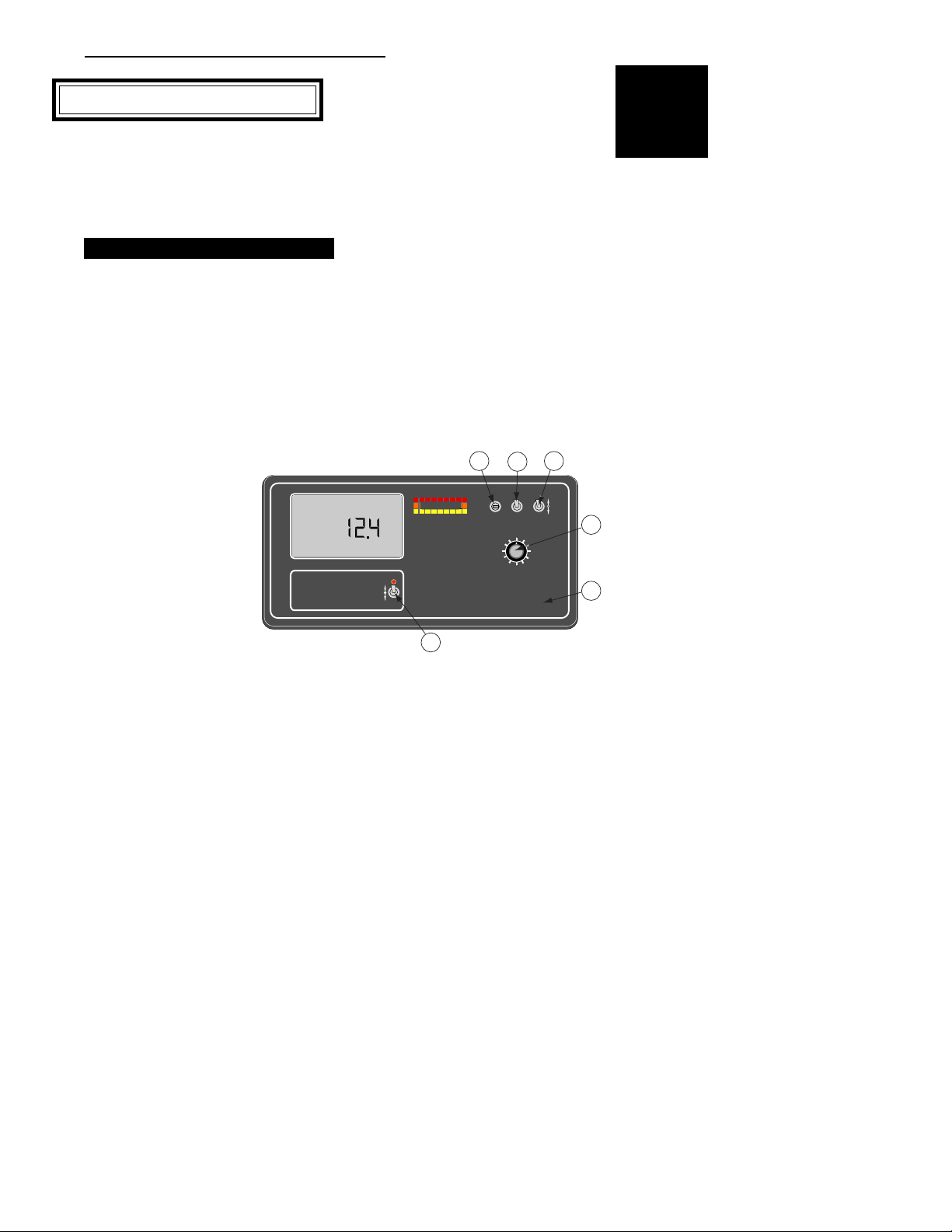
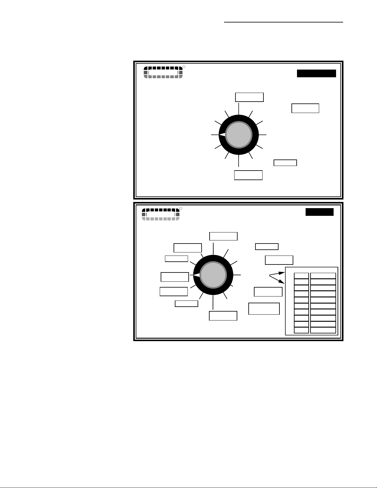
FIG. 1-1. TASC CONSOLE SWITCHES AND INDICATORS 1-1
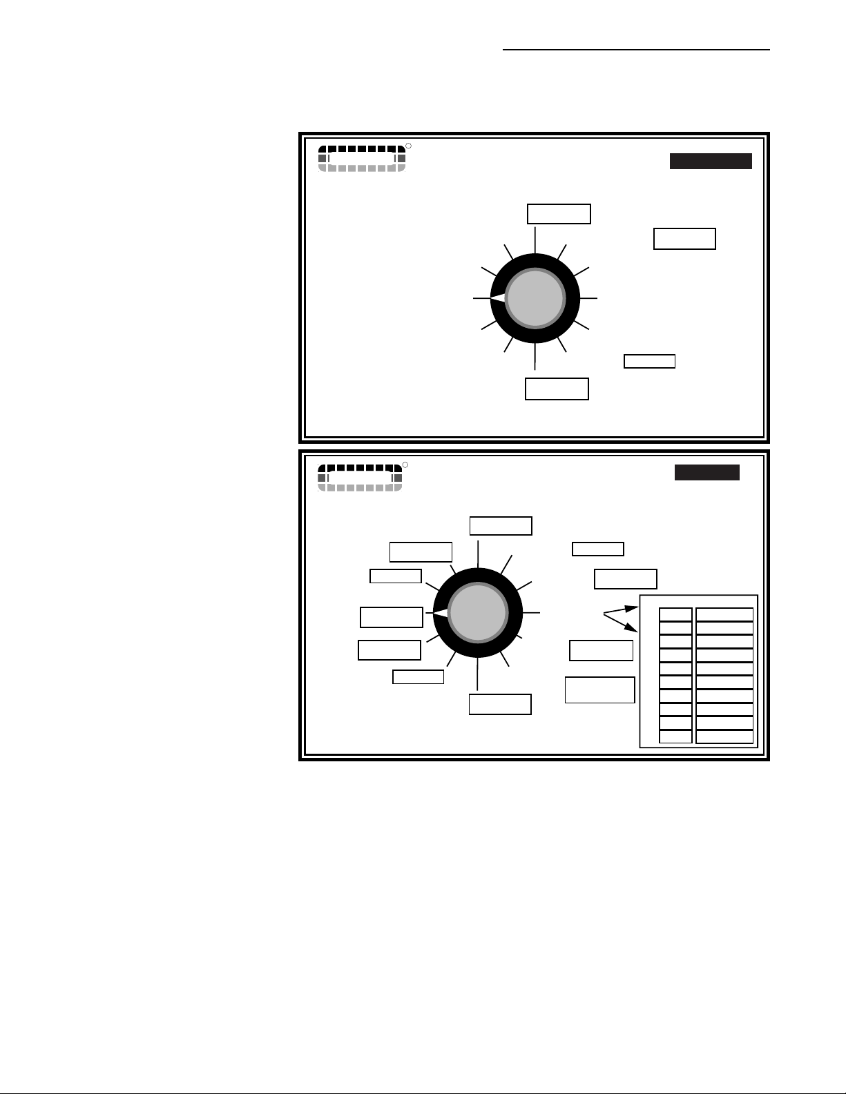
IG. 1-2. DISPLAY SELECTO R FUNCTIONS - OPERATE MODE 1-3
F
F
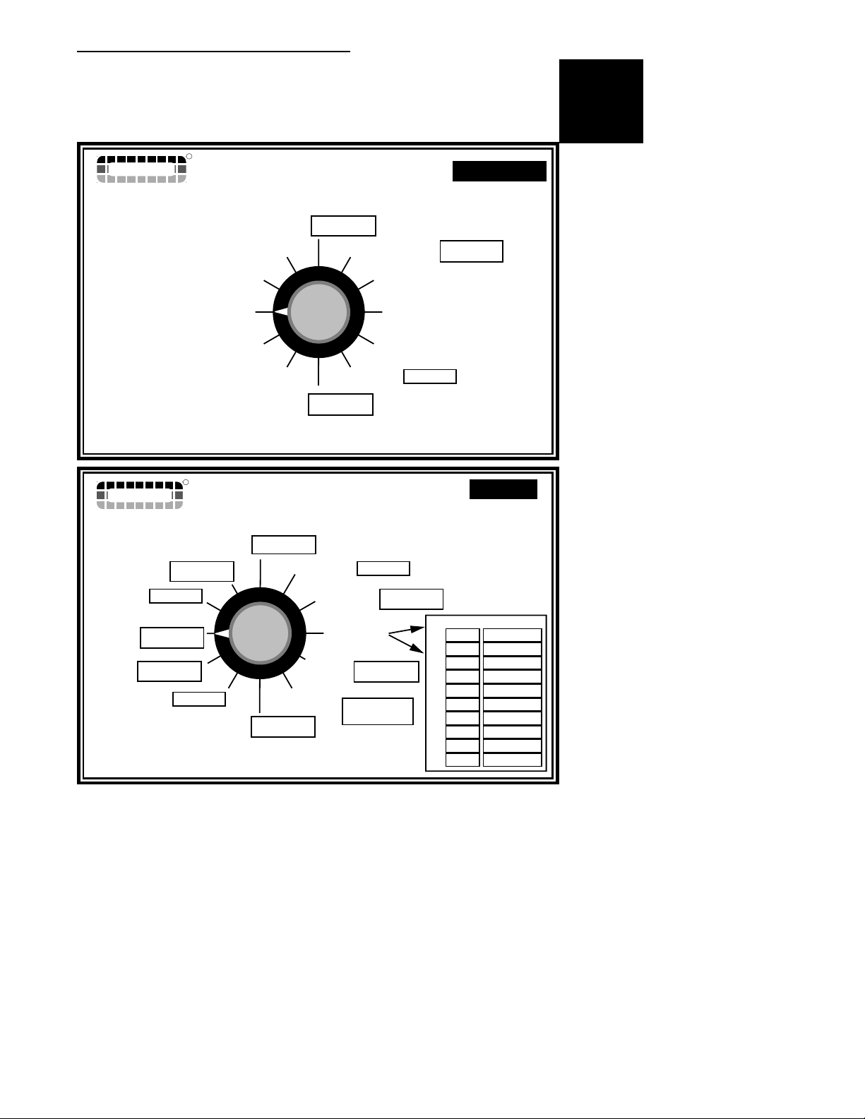
IG. 1-3. DISPLAY SELECTOR FUNCTIONS - SET-UP MODE 1-4
IG. 1-4. TASC 6100 DEFAULT VALUES - LIQUID STANDARD MODE 1-8
F
F
IG. 1-5. TASC 6100 DEFAULT VALUES - LIQUID PRESSURE MODE 1-9
FIG. 1-6. TASC 6100 DEFAULT VALUES - GRANULAR MODE 1-10
IG. A1 - TYPICAL FLOW/PRESSURE B ASED WIRING DIAGRAM A-2
F
F
IG. A 2. TYPICAL FLOW/PRESSURE BASED PLUMBING D IAGRAM A-3
IG. A 3. TYPICAL TASC 6100 GRANULAR SYSTEM WIRING DIAGRAM A-4
F
F
IG. A 4. TASC 6100 W/AUTO TIP CONTROL WIRING DIAGRAM A-5
FIG. A 5. SERVICE FORM A-6
IG. B-1 TASC 6100 SYSTEM DATA FLOW B-2
F
F
IG. B-2. TASC 6100 CONSOLE B-3
IG. B-3. GROUND SPEED R ADAR B-4
F
F
IG. B-4. FLOWMETER B-5
FIG. B-6. 100 PULSE SENSOR B-5
IG. B-5. PRESSURE SENSOR B-5
F
F
IG. B-7. FLOW CONTROL V ALVE B-6
IG. B-8. BOOM CONTROL S WITCHBOX B-7
F
F
IG. B-10. DATA LINK B-7
FIG. B-9. AUTO TIP CONTROL BOX B-7
98-05018
R2
V
CE & STANDARD V ERSION
Page 6

98-05018
Mid-T
ech
R2
HOW TO USE THIS MANUAL
TASC 6100
his manual is designed to provide you with the basic
information needed to set up and operate the Mid-Tech
T
TASC 6100 control system. Actual procedures may vary
somewhat, depending on the configuration of your system.
When you see "Mitch", he is pointing out special information
that you should be aware of, regarding safety, preventing
console damage, an easier way to perform an operation, etc..
Below is a listing of the chapters in this manual, along with a
brief description of the information found in each chapter.
Chapter 1 - Switches and Controls - Lists each control switch,
on the face of the console, and gives a brief description of its
use.
Chapter 2 - Calibration and Setup - Takes you, step by step,
through the calibration of each sensor providing input to the
console, and entering other information the console needs to
perform the functions you require.
Chapter 3 - Operation - Briefly describes how to initiate the
application operation.
Chapter 4 - Trouble shooting - Lists possible causes and
remedies for the error codes that appear on the TASC display
if the console detects a problem.
®
M
id
-
T
e
c
h
Chapter 5 - Maintenance - Covers the basic maintenance
needed to keep your system operating at peak performance.
Chapter 6 - Emergency Operations - Suggests ways to operate,
under reduced accuracy, in the event of a major fault.
Appendix A - Sample system wiring and plumbing diagrams.
Appendix B - System Overview - Describes the major compo-
nents of the TASC system and their individual functions in
application control.
Appendix C - Glossary/Tables
Back Cover - Quick Start/Quick Set Up Guides
CE & STANDARD V ERSION
VI
Page 7
TASC 6100
CHAPTER 1 SWITCHES AND CONTROLS
everal switches and indicators serve as the
interface between the operator and the Mid-
S
Tech control system.
CONSOLE SWITCHES AND INDICATORS
his section shows the location of each switch
and indicator found on the TASC 6100 control
T
console and discusses its function in both the
Operate and Setup modes.
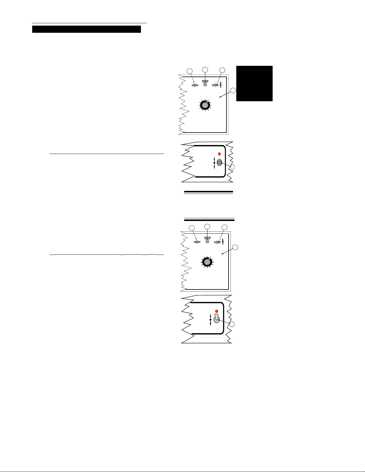
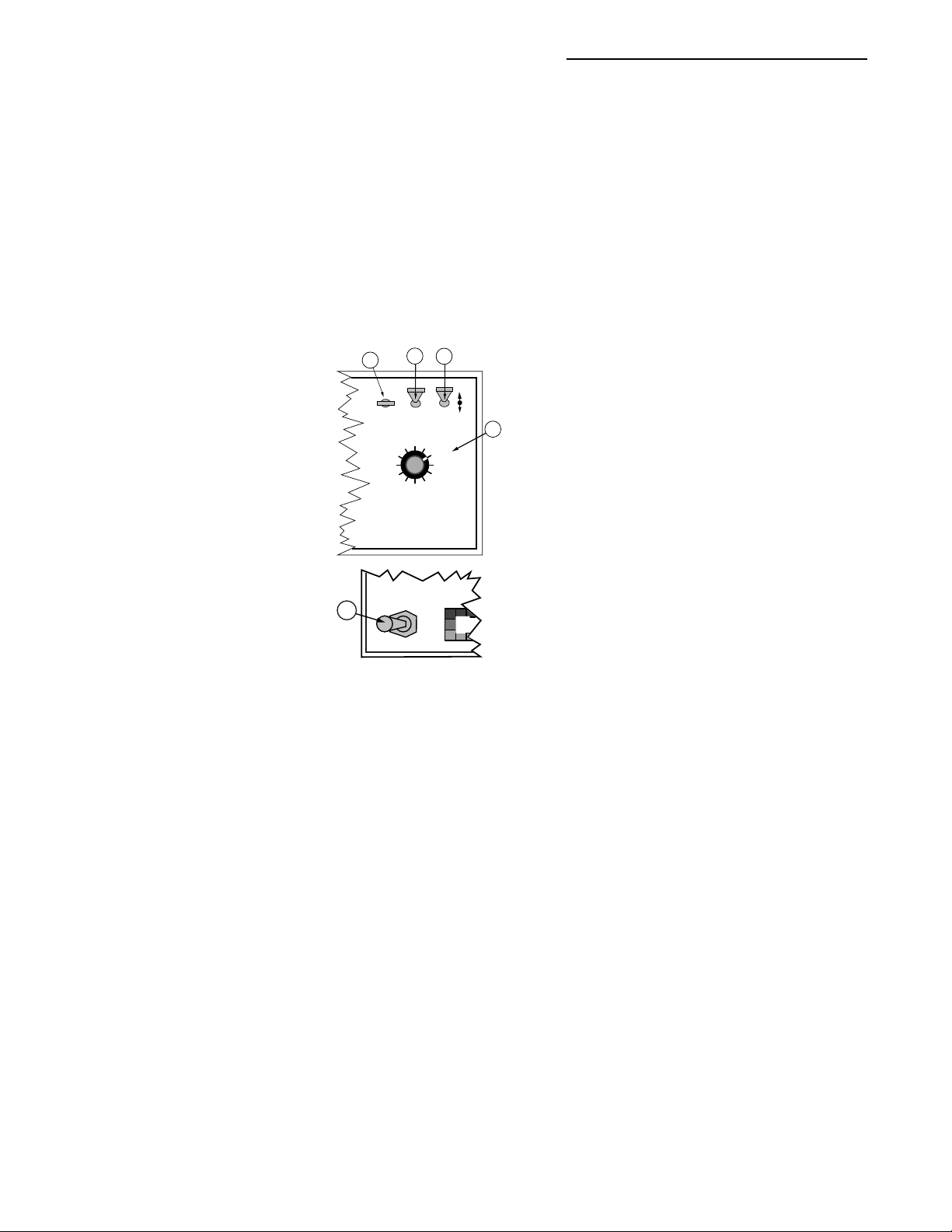
POWER SWITCH
The power switch (see #1 in Fig. 1-1) controls power
to the console. The CE console has an "Auto Power
Down" feature which
powers the console off
after a operator selectable
time has elapsed. The
console has a nonvolatile
memory so it "remembers"
the constants and data
previously entered, even
with the power removed.
NOTE: The “Auto Power Down Feature is only
available on the CE version of the console (CE
designation label on back of console).
Flow
TASC-6100
Rate Controller
Gal./
Standard Rate
Alt.-Rate
98-05018
R2
Switches
& Cont.
3
2
1
ON OPERATE INC.
MID-TECH
-Ac
MIDWEST TECHNOLOGIES, INC.
OFF
®
OFF SET- UP
DEC.
%Rate
Product Vol.
Appl. Rate
Fan RPM
Total Applied
Area
Width
Speed
Distance
Scan
PSI/Prime
Test
Speed
DISPLAY SELECTOR
123 4567 89
BOOMS
6
Fig. 1-1. TASC
Console Switches and
Indicators
4
5
MODE SELECTOR SWITCH
The Mode Selector switch (see #2 in Fig. 1-1)
switches between the OPERATE and SET-UP modes
of the control console. This switch must be in the
“OPERATE” position when applying product. The
“SET-UP” position is used for entering set-up
information into the console. In the SET-UP Mode an
“Err” message appears if a position which can not be
programmed is selected.
1-1
CE & STANDARD V ERSION
Page 8

98-05018
R2
TASC 6100
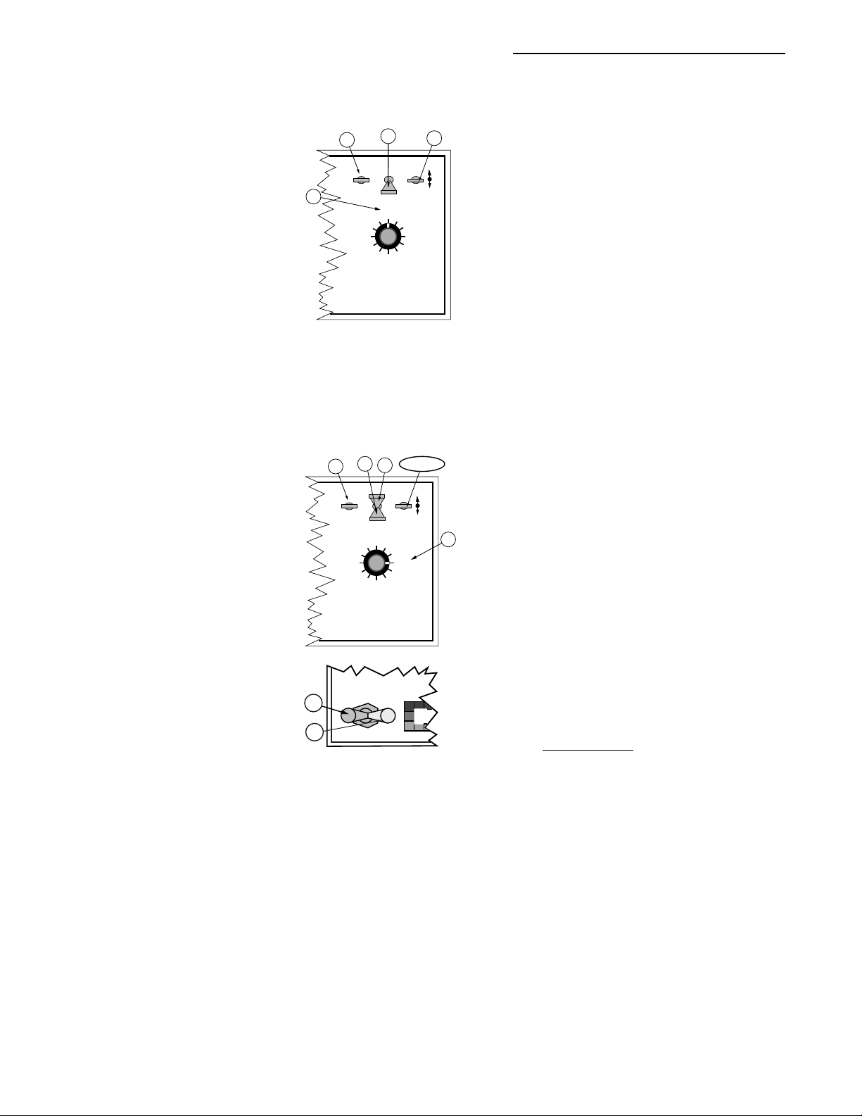
INC / DEC SWITCH
The Increase/Decrease (INC/DEC) switch (see #3 in
Fig. 1-1) is used, in both the OPERATE and SET-UP
modes, to adjust the values appearing in the display.
BOOM SECTION “ON/OFF” INDICATORS
The boom section On/Off indicators (see #5 in Fig. 1-
1) indicate which boom sections the operator has
selected. When a boom is turned on, its indicator is lit.
There are a maximum of nine boom sections available.
RATE SWITCH
The Rate Selector switch (see #6 in Fig. 1-1) is a three
position switch that allows the operator to select
either a pre-selected standard rate, an alternate rate, or
stop the application.
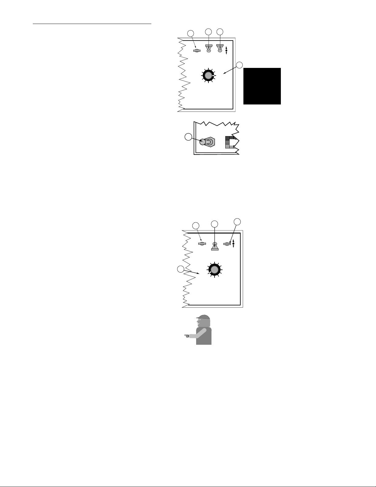
DISPLAY SELECTOR SWITCH
The Display Selector (see #4, Fig. 1-1) is used to
choose which of the console functions is displayed on
the screen and is available for setting by the operator.
Display Selector - Operate Mode (Liquid)
(See Fig. 1-2)
Speed: The current vehicle speed.
Area: Area Accumulator #1. The total area treated
since the counter was last reset.*
Fan RPM: Not used in liquid mode.
Product Vol: Amount of product aboard the vehicle.
Value counts down as the product is applied and
alarm sounds when 10 % of the full load is left.**
CE & STANDARD V ERSION
1-2
Page 9

TASC 6100
®
OFF
567 89
MPH
123
BOOMS
OFF
DEC.
4
OFF
MIDWEST TECHNOLOGIES, INC.
% Rate: The percent
of programmed
application rate
at which the
MPH
system is applying product.***
Application Rate:
Displays the
target application
rate when the
ground speed is
zero or all booms
are OFF.** The
Product Vol.
TASC-6100
Fan RPM
Rate Controller
Speed
%Rate
Area
Scan
DISPLAY SELECTOR
Test
Speed
PSI/Prime
Appl. Rate
Total Applied
Width
Distance
actual application
rate is displayed
here once
application has started.
Total Applied: The total volume of product applied
since the last time the counter was reset, as
measured by the pressure sensor or flow meter.*
OPERATE
MID-TECH
SET- UP
MIDWEST TECHNOLOGIES, INC.
98-05018
R2
OPERATE
Scan
SET- UP
%Rate
Test
Speed
4
INC.
DEC.
Appl. Rate
Total Applied
Width
Distance
PSI/Prime
567 89
ON
®
OFF
Product Vol.
Fan RPM
Area
Speed
DISPLAY SELECTOR
123
BOOMS
Fig. 1-2. Display Selector
Functions - Operate Mode
Switches
& Cont.
Impl. Width: The active boom width, (total of all
boom sections turned ON).
Distance: The total distance traveled since the last
time the counter was reset.
PSI/Prime: Used to open the control valve during
product pump priming, for fast unload, and to
display boom pressure when operating in pressure
based mode.
Test Speed: The speed the console uses for stationary
tests of the sprayer.**
Scan: The display scans Speed, Area #1, Product
Vol., Application Rate, Total Applied, and Fan
RPM, stopping at each position for approximately
two seconds before automatically cycling to the
next.
* Totals can be zeroed in
this mode.
** Values are programmable
in this mode.
*** Values changeable by a %
increase or decrease.
1-3
CE & STANDARD V ERSION
Page 10

98-05018
R2
Product Vol.
Fan RPM
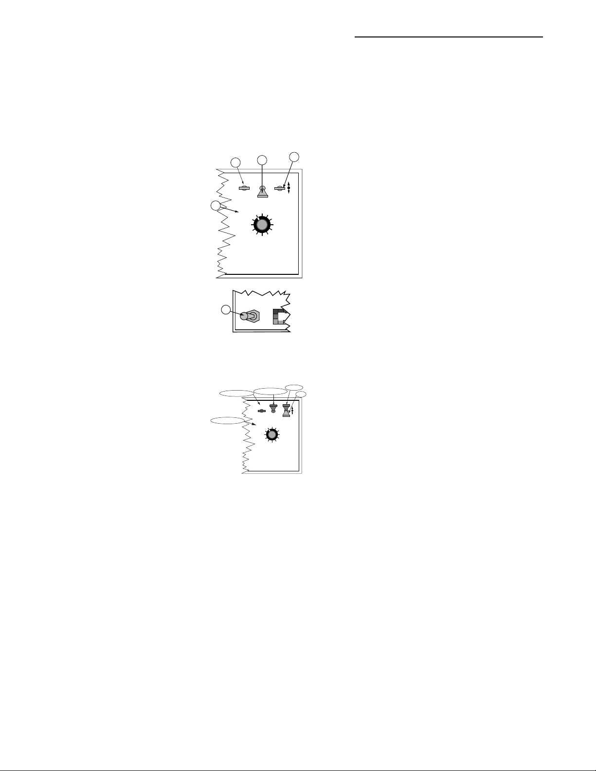
Fig. 1-3. Display Selector
Functions - Set-Up Mode
%Rate
TASC-6100
Rate Controller
Area
Speed
Scan
Test
Speed
DISPLAY SELECTOR
PSI/Prime
MPH
Appl. Rate
Total Applied
Width
Distance
TASC 6100
Display Selector - Setup Mode (Liquid)
(See Fig. 1-3)
Speed: Ground speed
OPERATE
INC.
ON
OPERATE
SET- UP
®
OFF
Product Vol.
Fan RPM
Area
Speed
Scan
DISPLAY SELECTOR
123
BOOMS
SET- UP
%Rate
Appl. Rate
Total Applied
Width
Distance
PSI/Prime
Test
Speed
567 89
4
DEC.
MID-TECH
MIDWEST TECHNOLOGIES, INC.
mode, can be set to zero to remove the fan
RPM reading from the scan feature.**
Product Volume: Used to set the full load value of the
vehicle.**
% Rate: The percent rate change value (the percent
by which the programmed application rate can be
changed with each activation of the INC/DEC
switch).**
override (GSO) value.**
Area: Area Accumulator
#2. The total area treated
since the counter was last
reset.*
Fan RPM: The current fan
RPM. calibration number.
Since not used in liquid
* Totals can be zeroed in
this mode.
** Values are programmable
in this mode.
*** Values changeable by a %
increase or decrease.
CE & STANDARD V ERSION
Application Rate: Psi mode - A flow sensor cal. #
correction factor that allows for corrections due to
differences in product viscosities without changing
the base cal. #. STnrd and rEFLO modes - ERR, No
function in this mode.
Total Applied: The pressure sensor or flow meter
calibration number. NOTE: Must have all booms
ON when in REFLOW Mode.**
Width: Individual boom section widths. The display
cycles through the individual boom sections, in
order, unless a particular boom switch is activated
and the boom master switch is ON.**
Distance: The current distance calibration number.**
PSI/Prime: The current console operating mode.**
Test Speed: The current test speed.**
Scan: ERR, No function in SETUP mode.
1-4
Page 11

TASC 6100
Display Selector - Operate Mode (Gran.)
(See Fig. 1-2)
Speed: The current vehicle speed.
Area: Area Accumulator #1. The total area treated
since the counter was last reset.*
Fan RPM: The current speed of the fan (spinners).
Product Vol.: Amount of product aboard the ve-
hicle.**
% Rate: The percent of programmed application rate
at which the product is being applied.***
Application Rate: Displays the target application rate,
when the ground speed is zero or all booms are
OFF. ** Once application begins, the actual
application rate is displayed here.
Total Applied: The total volume applied since the
accumulator was last reset, as measured by the rate
sensor.*
98-05018
R2
Switches
& Cont.
Impl. Width: The active spread width, (total of all
spreader sections turned “ON”).
Distance: The total distance traveled since the last
time the counter was reset.
Prime: Used to open the control valve. It can be used
in the granular application to unload the vehicle at
its maximum discharge rate.
Test Speed: The speed the console uses for stationary
tests of the spreader.**
Scan: The display scans Speed, Area #1, Product
Volume, Application Rate, Total Applied, and Fan
RPM (if Fan RPM Cal # not set to zero). The
display stops at each position for approximately
two seconds before automatically cycling to the
next.
1-5
* Totals can be zeroed in
this mode.
** Values are programmable
in this mode.
*** Values changeable by a %
increase or decrease.
CE & STANDARD V ERSION
Page 12

98-05018
R2
TASC 6100
Display Selector - Set-Up Mode (Gran.)
(See fig. 1-3)
Speed: Ground Speed Override (GSO) value.**
Area: Area Accumulator #2. The total area treated
since the counter was last reset.*
Fan RPM: The current fan RPM calibration
number. This cal # can be set to zero to remove the
fan RPM reading from the scan feature.**
Product Volume: Used to set the full load capacity of
the vehicle.**
% Rate: The percent rate change value (the percent
by which the programmed application rate can be
changed with each activation of the INC/DEC
switch).**
Application Rate: Product density.**
Total Applied: The rate sensor calibration number
[spreader constant].**
* Totals can be zeroed in
this mode.
** Values are programmable
in this mode.
*** Values changeable by a %
increase or decrease.
CE & STANDARD V ERSION
Width: Individual boom section widths.**
Distance: The current distance calibration number.**
Prime: The current console operating mode.**
Test Speed: The current test speed.**
Scan: Err, No function in the SETUP mode.
IMPLEMENT STATUS INPUT
n external “Implement Status” input can be
used to override the TASC control. The
A
VDC) on the boom interface cable sense line. As long
as this condition is present, the control console
operates normally. If the voltage is interrupted, the
control console automatically stops applying. At the
same time, the control console will either "HOLD" or
input must present a positive voltage (+12.0
1-6
Page 13

TASC 6100
Mid-T
ech
"CLOSE" the control valve, depending on the
response selected by the operator. (See Page 2-7).
This feature allows the operator to control the
operation of the control valve through the normal
operation of the vehicle. The implement status input
can be used to sense the ON/OFF condition of the
main vehicle pump switch, a separate Master switch,
or, an external switch sensing an implement "UP"/
"DOWN" condition.
GROUND SPEED OVERRIDE SWITCH (GSO)
f your TASC system includes an optional MIDTECH® Boom Control Switch Box, the GSO
I
switch is already installed. An optional, externally
mounted, GSO switch can be used to temporarily
operate the vehicle using a pre-selected GSO minimum speed rather than the actual speed registered by
the ground speed sensor. The override feature is used
to allow the vehicle to reach the application rate
quickly when starting from a complete stop or to
maintain a good application pattern when the vehicle
is moving at very low ground speeds. It can also be
used to allow the operator to flush or empty the tank
of a sprayer, or empty the bed of a spreader, from the
cab, with the vehicle stopped.
98-05018
R2
Fig. B-8, in Appendix B,
shows a “Boom Control
Switch Box” which incorporates the Implement Status
Switch and the GSO function
into one switch. The “OFF”
position provides a Status
Switch “OFF” condition,
“AUTO” furnishes Status
Switch ON, and “GSO”
activates the GSO function.
Other methods of controlling
these functions are also
available. This switchbox
also includes an individual
ON/OFF switch for each
boom section.
Switches
& Cont.
The control console operates normally as long as the
GSO switch condition is open (OFF). Whenever the
override switch is closed (ON) and the actual ground
speed is
less than the GSO Speed, the control console
automatically uses the GSO Speed to control application rate. As soon as the switch reverts to its normally
open (OFF) condition, or the actual ground speed
increases above the preset GSO speed, the control
console will adjust the rate based on the actual ground
speed.
CAUTION: Controlling application rates based on
a GSO Speed is not as accurate as using the actual
ground speed. When GSO is being used and the true
ground speed is less than the GSO speed", the
console sounds an alarm and the display flashes a
"Too Slow" message to warn the operator of over
application.
1-7
M
id
-T
e
c
h
CE & STANDARD V ERSION
Page 14
98-05018
R2
TASC 6100
MID-TECH
MIDWEST TECHNOLOGIES, INC.
Specialists In Control System Electronics Since 1983
R
TASC 6100, DISPLAYED VALUES WHEN IN
Use INC switch to set full load,
INC/DEC to change
Product Vol.
Fan RPM
Area
Use DEC switch to zero display
Speed
Test Speed
Default values shown in upper left of boxes.
MID-TECH
MIDWEST TECHNOLOGIES, INC.
Specialists In Control System Electronics Since 1983
Product Vol.
Fan RPM
Full Load Amount
500
2.00
R
TASC 6100, DISPLAYED VALUES WHEN IN
Rate Change Increment
10
% Rate
Use INC/DEC switch to change up or down
100
% Rate
Scan
10.0
Use INC/DEC switch to change up or down
Application Rate
Total Applied
Application Rate
Use INC/DEC switch to change up or down
Total Applied
Use DEC switch to zero display
Impl. Width
Distance
PSI/Prime
Correction factor
1.00
Hold increase switch to drive valve OPEN
-----
Rate Sensor Cal#
71.0
OPERATE
SOFTWARE VER. 1.30
LIQUID STD MODE
Preset #1
10.0/12.0
SET-UP
SOFTWARE VER. 1.30
LIQUID STD MODE
Preset #1
0.0
Area
Ground Speed Override
7.0
Speed
Scan
Err
Test Speed
Default values shown in upper left of boxes.
Use the INC/DEC switch to change values.
CE & STANDARD V ERSION
Impl. Width
Distance Sensor Cal#
Distance
PSI/Prime
10.0/
1000
DEC sets to granular
INC sets to liquid
Stnrd L
Fig. 1-4. TASC 6100 Default Values
- Liquid Standard Mode
1-8
Default Custom
960
C
120
1
2
200
3
320
4
200
5
120
6
7
0
8
0
9
0
0
99362
Page 15
TASC 6100
98-05018
R2
Switches
& Cont.
MID-TECH
MIDWEST TECHNOLOGIES, INC.
Specialists In Control System Electronics Since 1983
R
TASC 6100, DISPLAYED VALUES WHEN IN
Use INC switch to set full load,
INC/DEC to change
Product Vol.
Fan RPM
Use DEC switch to zero display
Area
Speed
Test Speed
Default values shown in upper left of boxes.
MID-TECH
MIDWEST TECHNOLOGIES, INC.
Specialists In Control System Electronics Since 1983
Product Vol.
Fan RPM
Full Load Amount
500
2.00
R
TASC 6100, DISPLAYED VALUES WHEN IN
Rate Change Increment
10
% Rate
Use INC/DEC switch to change up or down
100
% Rate
Scan
10.0
Use INC/DEC switch to change up or down
Application Rate
Total Applied
Application Rate
Use INC/DEC switch to change up or down
Total Applied
Use DEC switch to zero display
Impl. Width
Distance
PSI/Prime
Correction factor
1.00
Hold increase switch to drive valve OPEN
Ps---
Rate Sensor Cal#
10.0/12.0
OPERATE
SOFTWARE VER. 1.30
LIQUID PSI MODE
Preset #1
10.0
SET-UP
SOFTWARE VER. 1.30
LIQUID PSI MODE
Preset #1
Area
0.0
Ground Speed Override
7.0
Speed
Scan
Default values shown in upper left of boxes.
Use the INC/DEC switch to change values.
Err
Test Speed
10.0
Fig. 1-5. TASC 6100 Default Values
Impl. Width
Distance Sensor Cal#
Distance
PSI/Prime
1000
DEC sets to granular
INC sets to liquid
PSi
- Liquid Pressure Mode
1-9
Default Custom
960
C
120
1
2
200
3
320
4
200
5
120
6
7
0
8
0
9
0
0
99362
CE & STANDARD V ERSION
Page 16
98-05018
R2
TASC 6100
MID-TECH
MIDWEST TECHNOLOGIES, INC.
Specialists In Control System Electronics Since 1983
R
TASC 6100, DISPLAYED VALUES WHEN IN
Use INC switch to set full load,
INC/DEC to change
Product Vol.
Fan RPM
Use DEC switch to zero display
Area
Speed
Test Speed
Default values shown in upper left of boxes.
MID-TECH
MIDWEST TECHNOLOGIES, INC.
Specialists In Control System Electronics Since 1983
Product Vol.
Fan RPM
Full Load Amount
10750
2.00
R
TASC 6100, DISPLAYED VALUES WHEN IN
Rate Change Increment
10
% Rate
Use INC/DEC switch to change up or down
100
% Rate
Scan
10.0
Use INC/DEC switch to change up or down
Application Rate
Total Applied
Application Rate
Use INC/DEC switch to change up or down
Total Applied
Use DEC switch to zero display
Impl. Width
Distance
Hold increase switch to drive valve OPEN
PSI/Prime
Density
65.0
-----
Rate Sensor Cal#
1630.0
OPERATE
SOFTWARE VER. 1.30
GRANULAR MODE
Preset #1
200/250
SET-UP
SOFTWARE VER. 1.30
GRANULAR MODE
Preset #1
0.0
Area
Ground Speed Override
7.0
Speed
Scan
Err
Test Speed
Default values shown in upper left of boxes.
Use the INC/DEC switch to change values.
CE & STANDARD V ERSION
Impl. Width
Distance Sensor Cal#
Distance
PSI/Prime
10.0
1000
DEC sets to granular
INC sets to liquid
Stnrd C
Fig. 1-6. TASC 6100 Default Values
- Granular Mode
1-10
Default Custom
720
C
360
1
2
360
3
0
4
0
5
0
6
7
0
8
0
9
0
0
99362
Page 17

TASC 6100
Mid-T
ech
CHAPTER 2 CALIBRATION
NOTE: PLEASE READ THROUGH THE FOLLOWING SECTIONS COMPLETELY BEFORE YOU
BEGIN CALIBRATION!
pecific information about your applicator (i.e.
application rates, boom widths, test speed, etc.)
must be programmed into the control console and
S
the flow/rate and ground speed sensors must be calibrated
before the system is ready to use. The calibration and set
up procedures are not difficult but must be followed
precisely in order to get the maximum possible accuracy
out of the system.
SELECTING THE APPLICATION PROGRAM
erify that the proper console application pro
gram is selected.
8
To view the program currently selected, set the Mode switch
to Setup and the Display Selector to PSI/Prime.
M
id
-
T
e
c
h
98-05018
R2
Setup
& Cal.
Pump L PSi(bAr) is LIQUID PRESSURE application (normal pressure based spraying)
Pump L STnrd is STANDARD LIQUID application (normal flow based spraying)
Pump L rEFLO is LIQUID REFLOW application (for use on some European sprayers)
Pump C STnrd is standard GRANULAR application (single conveyor spreaders)
Pump C SPLit is GRANULAR SPLIT DRIVE application (dual conveyor spreaders)
To change programs, hold the INC. switch up to set LIQUID
and cycle between standard, reflow, and pressure. Hold the
DEC. switch down to set GRANULAR and cycle between
standard and split drive. The display changes about every
ten seconds. The program being displayed, when the INC./
DEC. switch is released, is the program selected. If you have
a question about which application to use, check with your
dealer or call MID-TECH Customer Service.
SELECTING ENGLISH OR METRIC, UNITS
he control console is capable of displaying either
US or Metric units of measure.
T
2-1
CE & StandardVersion
Page 18
98-05018
R2
TASC 6100
UNITS FOR EACH DISPLAY SELECTOR SWITCH POSITION
(Liquid Mode)**
POSITION US METRIC
Speed Miles/Hour (mph) Kilometers/Hour (kmph)
Field Area Acres (acre) Hectares (ha)
Total Area Acres (acre) Hectares (ha)
Product Vol. US Gallons (gal.) Liters (l)
Appl. Rate US Gallons/acre (gpa) Liters/Hectare (l/ha)
Total Applied US Gallons (gal.) Liters (l)
Impl. Width Inches - Feet (in., ft.) Meters (m)
Distance Feet - Miles (ft.-miles)* Meters - Kilometers (m-km)*
Test Speed Miles/Hour (mph) Kilometers/Hour (kmph)
UNITS FOR EACH DISPLAY SELECTOR SWITCH POSITION
(Granular Mode)**
POSITION US METRIC
Speed Miles/Hour (MPH) Kilometers/Hour (KPH)
Field Area Acres (Ac) Hectares (-Ha)
Total Area Acres (Ac) Hectares (-Ha)
Product Vol. Pounds (lb) Kilograms
Appl. Rate pounds/Acre (lb/Ac) Kilograms/Hectare (-Ha)
Total Applied Pounds-Tons (lb -Tons) Kilograms-Metric Tons
Impl. Width Inches-Feet (In.-Ft.) Meters (Meters)
Distance Feet-Miles (Ft.)* Meters-Kilometers (Meters)*
Test Speed Miles/Hour (MPH) Kilometers/Hour (KPH)
Prod. Density Pounds/Cubic Ft. (Cu Ft.) Kilograms/Tenths Meter3 (Meters Cu)
* No units displayed after roll over of feet to miles or meters to kilometers
** Items in parenthesis are the abbreviations that appear on the screen.
A-1
ON
OFF SET- UP DEC.
Product Vol.
Fan RPM
A-3
CE & S
Area Impl. Width
Speed
Scan
DISPLAY SELECTOR
123456789
BOOMS
TANDARD V ERSION
A-2
OPERATE INC.
% Rate
Application Rate
Total Applied
Distance
PSI/Prime
Test
Speed
CHANGING UNITS
A. Set the console switches to the following positions:
B
1. Power ON
2. Mode Selector OPERATE
3. Display selector Speed
The display shows the current speed units.
B. Hold down the INC./DEC. switch for approximately
5 sec. The display alternates between MPH (US) and
KPH (Metric). Release the switch when the mode
that you desire is being displayed.
2-2
Page 19
TASC 6100
LIQUID/GRANULAR COMMON SETUP ITEMS
SETTING APPLICATION RATES
98-05018
R2
he TASC 6100 system is designed to maintain a
constant, pre-selected application rate. In order for
T
the control console to do this, the operator must
enter the desired application rate. Two, switch selectable,
rates can be pre-programmed into the console.
Standard Rate
A. Set the console switches to the following positions:
1. Power ON
2. Mode Selector OPERATE
(APPLICATION RATE IS SET IN THE OPERATE MODE!!!)
3. Display Selector Application Rate
4. Rate switch Standard Rate
The display shows the current application rate.
B. Use the INC./DEC. switch to set the desired rate.
Alternate Rate
C. Set the console switches to the following positions:
1. Power ON
2. Mode Selector OPERATE
(APPLICATION RATE IS SET IN THE OPERATE MODE!!!)
3. Display Selector Application Rate
4. Rate switch Alt.- Rate
The display shows the current application rate.
D. Use the INC./DEC. switch to set the desired rate.
A-2
A-1
ON
OPERATE INC.
OFF SET- UP DEC.
% Rate
Product Vol.
Fan RPM
Area Impl. Width
Speed
Scan
Test
Speed
DISPLAY SELECTOR
123456789
BOOMS
Alt.-Rate
Standard Rate
Application Rate
Total Applied
Distance
PSI/Prime
OFF
B
Setting the APPLICATION RATE to 0.0 will
turn off the flow
control function.
A-2
A-1
ON
OPERATE INC.
OFF SET- UP DEC.
% Rate
Product Vol.
Fan RPM
Area Impl. Width
Speed
Scan
Speed
DISPLAY SELECTOR
123456789
BOOMS
Test
Application Rate
Total Applied
Distance
PSI/Prime
B
A-3
Setup
& Cal.
A-4
A-3
SETTING THE % RATE CHANGE
his feature allows the operator to change the
application rate “ON THE GO” with a simple
T
actuation of the INC./DEC. switch. The amount of
change each switch actuation makes is proportional to
the value programmed into this position, (e.g. 20 =20%
2-3
Alt.-Rate
Standard Rate
OFF
A-4
CE & StandardVersion
Page 20
98-05018
R2
A-2
A-1
ON
OPERATE INC.
A-3
A-4
E
OFF SET- UP DEC.
% Rate
Product Vol.
Fan RPM
Area Impl. Width
Speed
Scan
Test
Speed
DISPLAY SELECTOR
123456789
BOOMS
A-2
A-1
Fan RPM
123456789
BOOMS
OFF
E
ON
OPERATE INC.
OFF SET- UP DEC.
% Rate
Product Vol.
Area Impl. Width
Speed
Scan
Test
Speed
DISPLAY SELECTOR
MASTER
ON
Application Rate
Total Applied
Distance
PSI/Prime
B, C, D, E
Application Rate
Total Applied
Distance
PSI/Prime
MI
TASC 6100
change in the target rate). For example, with the application rate set to 10.0 gallons per acre, a single actuation of
the INC. switch causes the system to control flow at the
rate of 12.0 gallons per acre (10.0 + 20% = 12.0).
B
A. Set the console switches to the following positions:
1. Power ON
2. Mode Selector SET-UP
3. Display Selector % Rate
The display shows the current % change value.
B. Use the INC./DEC. switch to set this number to the
desired % change value.
SETTING BOOM WIDTHS
he MID-TECH control console is designed to
automatically compensate for changes in the swath
T
width, caused by turning boom sections on or off.
To accurately respond to changes in swath width, the
console must know the length of each boom section. Use
the following procedure to set boom section widths.
A. Set the console to the following positions;
A-3
1. Power ON
2. Mode Selector SET- UP
3. Display Selector Impl. Width
4. Boom switches OFF
(or Master switch)
The display cycles through each boom position (1
through 9) and displays its current width in inches
(meters).
B. As each boom position appears on the display, use
the INC./DEC. switch to set the display to the
number of inches (meters) covered by that boom.
Repeat for each section.
CE & S
TANDARD V ERSION
C. Set all unused boom sections to a width of zero “0”
inches (meters). This insures that accidentally
turning a boom switch ON doesn’t affect the control
console. (An ERROR 0 Boom # will then result if an
unused boom gets accidentally turned on)
2-4
Page 21

TASC 6100
D. Finally, let the boom width display cycle through the
boom sections until it shows “Boom C”. When the
“C” width is displayed, set it to the normal operating
width of the entire sprayer, in inches (meters), using
the INC./DEC. switch.
E. The boom width is now set. Turn all booms ON and
return to the OPERATE mode. The new total boom
width will be displayed in feet (meters). If this does
not agree with your total applicator width, check the
individual boom widths, ( steps B and C).
Record these calibration numbers
on last page of manual.
DISTANCE CALIBRATION - GROUND SPEED SENSOR
General Considerations and Initial Calibration
Numbers
he control console must be calibrated for the
ground speed sensor installed to ensure accurate
T
application rates. The procedure involves physically measuring an accurate distance along a road or
field, driving the vehicle through that distance, mathematically comparing the distance computed by the
control console to the actual measured distance, and
making any necessary adjustments to the distance
calibration number. Follow the recommended procedure
below to ensure accuracy of operation.
98-05018
R2
Boom widths are
entered in inches in
the US system. For
example; for a liquid
boom with 7 nozzles
on 30" spacings, enter
210 for that boom.
There is no need to
convert to feet, the
control console does
that automatically
when it is switched
back to the Operate
Mode. (In metric, all
widths are entered in
meters.)
Setup
& Cal.
The distance calibration should be checked periodically
to maintain its accuracy. This is especially important if
the sensor mounting has become loose or has been
repositioned, or if the tires have been changed.
Use the following initial calibration numbers. It is
important to field calibrate the distance sensor to
insure maximum accuracy!
MID-TECH® COMPACT RADAR - 780
Dj RADAR - 1000
WHEEL SENSOR - 3500
SPEEDOMETER SENSOR - 3500
2-5
CE & StandardVersion
Page 22

98-05018
R2
A-1
ON
OFF SET- UP DEC.
Product Vol.
Fan RPM
Area Impl. Width
Speed
DISPLAY SELECTOR
A-2
OPERATE INC.
% Rate
Scan
Test
Speed
Application Rate
Total Applied
Distance
PSI/Prime
TASC 6100
B
A. Set the control console switches to the following
settings:
1. Power ON
2. Mode Selector SETUP
3. Display Selector Distance
A-3
The display shows the current distance calibration
value.
123456789
BOOMS
B. Use the INC./DEC. switch to enter the initial
distance calibration number suggested.
You can now perform the distance calibration.
Distance Calibration Procedure
The following procedure is recommended by MIDWEST
TECHNOLOGIES for establishing an accurate distance
calibration. NOTE: All boom switches should remain
OFF during the entire procedure.
A. Fill the vehicle 1/2 full of material (unless it is a pull
type unit with the speed sensor mounted on the tow
vehicle), to approximate average load conditions.
B. Measure a known distance of at least 400 ft. in a
field or roadway (preferably in terrain similar to that
being treated). A longer distance, allows for a more
accurate calibration.
C. Record the current distance cal. #, which can be
viewed using the switch settings shown in the
“G
ENERAL C ONSIDERATIONS AND INITIAL CALIBRATION
NUMBERS” section above. For this example assume
an initial cal. # of 760.
CE & S
TANDARD V ERSION
D. Move the vehicle to the starting point of the
measured distance.
E. Reset the distance accumulator to zero (see page 2-
11)
F. Drive the vehicle to the other end of the measured
distance at a speed of between five and ten miles per
hour. Distance will accumulate on the display.
2-6
Page 23

TASC 6100
G. Stop the vehicle at the measured distance end marker.
Compare the distance indicated by the console to the
actual measured distance, to determine how much
correction is necessary. For example: if the indicated
distance is 396 Ft. after driving over a 400 foot
range, the error in the distance calibration is 1.0%.
H. Calculate the new distance calibration number using
the following formula:
Measured distance
Indicated distance
Example:
400
x 760 = 768, the New DC#
396
NOTE: Use the same equation, regardless of the type of
distance sensor .
I. Enter the corrected cal. # using the switch settings
shown in the “GENERAL CONSIDERATIONS AND INITIAL
CALIBRATION NUMBERS” section above. Switch back to
the OPERATE mode. The distance accumulator
should now agree with the measured distance that
you traveled. If it doesn't , recheck your calculations.
x Old DC# = New DC#
98-05018
R2
Setup
& Cal.
RECORD THIS CALIBRATION NUMBER
LAST PAGE OF MANUAL.
ON
SETTING THE HOLD/CLOSE RESPONSE OF THE FLOW
CONTROL VALVE
he operator can select a "Hold" or "Close" response
of the flow control valve to both “Implement
T
Status switch” and “All Booms OFF" conditions.
These responses are independent of each other, allowing
the operator to select a "Hold" condition for one and a
"Close" for the other. Careful consideration should be
given to both conditions and the response selected for
your application.
Implement Status Switch
When the operator selects the "Hold" condition, deactivation of the Implement Status switch (open circuit) hold’s
the flow control valve in its current position. When
2-7
CE & StandardVersion
Page 24
98-05018
R2
TASC 6100
turning on the Implement Status switch (closed circuit)
the flow control valve is already open and product flow
is instantaneous. This response assumes that some other
device, such as a boom section valve, has stopped the
product flow.
When the operator selects the "Close" condition,
deactivation of the Implement Status Switch (open
circuit) automatically causes the flow control valve to
close. This response is preferred when it is necessary to
use the flow control valve to stop the product flow.
Use the following procedure to set the Status switch
response.
A-2
A-1
ON
OPERATE INC.
OFF SET- UP DEC.
% Rate
Product Vol.
Fan RPM
123456789
BOOMS
B
OFF
Application Rate
Scan
PSI/Prime
Test
Speed
DISPLAY SELECTOR
MASTER
ON
Total Applied
Distance
Area Impl. Width
Speed
C
A. Set the console to the following positions;
1. Power ON
2. Mode Selector OPERATE
A-3
3. Display Selector Total Applied
4. Boom switches OFF
(or Master switch)
B. Hold the INC./DEC. switch up to display the current
setting (Hold or Close). Continuing to hold the INC.
switch up will cause the display to alternate
between the two options at about three to ten
second intervals. The option appearing in the
display when the INC. switch is released is the
MI
response selected.
All Booms Off
When the operator selects a "Hold" condition, an “All
Booms OFF" condition (either all Boom switches or the
Master switch OFF) hold’s the flow control valve in its
current position. When the boom valves are turned ON
again the flow control valve is already open and product
flow is instantaneous.
CE & S
TANDARD V ERSION
When the "Close" condition is selected, an “All Booms
OFF" condition automatically causes the flow control
valve to close. This response is preferred when it is
necessary to use the flow control valve to stop the
product flow.
2-8
Page 25
TASC 6100
Mid-T
ech
Use the following procedure to set the “All Booms OFF”
response.
A. Set the console to the following positions;
1. Power ON
2. Mode Selector OPERATE
3. Display Selector Impl. Width
4. Boom switches OFF
(or Master switch)
B. Hold the INC./DEC. switch up to display the current
setting (Hold or Close). Continuing to hold the
switch up causes the display to alternate between the
two options at about three to ten second intervals.
The option appearing in the display when the INC.
Switch is released is the response selected.
SETTING THE GROUND SPEED OVERRIDE (GSO)
VALUE
o use the GSO feature, set the GSO value to the
minimum ground speed you want to control to
T
when the GSO switch is activated. This should be
the lowest speed at which the vehicle can dispense
material satisfactorily. If you do not intend to use this
feature, set this value to zero (0.0). (See page 1-7 for a
more complete description of GSO operation.)
Use the following procedure to set the GSO Speed.
A. Set the console to the following positions;
1. Power ON
2. Mode Selector SET-UP
3. Display Selector Speed
A-2
A-1
ON
OPERATE INC.
OFF SET- UP DEC.
% Rate
Product Vol.
Fan RPM
Area Impl. Width
Speed
Scan
Test
Speed
DISPLAY SELECTOR
123456789
BOOMS
MASTER
B
OFF
A-1
A-3
A-2
ON
OPERATE INC.
OFF SET- UP DEC.
% Rate
Product Vol.
Fan RPM
Area Impl. Width
Speed
Scan
Speed
DISPLAY SELECTOR
123456789
BOOMS
98-05018
R2
C
Application Rate
Total Applied
Distance
PSI/Prime
ON
Application Rate
Total Applied
Distance
PSI/Prime
Test
MI
A-3
B
Setup
& Cal.
B. Use the INC./DEC. switch to set the GSO speed to the
desired value.
CAUTION: When traveling at a speed slower than the
GSO speed setting, this feature will cause the product to
be applied at a rate consistent with the GSO speed,
rather than the true ground speed, possibly resulting in
serious over application. When Ground Speed Override is being used, and the true ground speed is less
2-9
M
id
-T
e
c
h
CE & StandardVersion
Page 26
98-05018
R2
A-1
ON
OPERATE INC.
OFF SET- UP DEC.
A-3
Product Vol.
Fan RPM
Area Impl. Width
Speed
Scan
DISPLAY SELECTOR
123456789
BOOMS
MASTER
B
OFF
A-2
% Rate
Test
Speed
ON
Application Rate
Total Applied
Distance
PSI/Prime
MI
than the pre-selected GSO Speed, the console will sound
an alarm and the display will flash a “Too Slow”
message to warn the operator of possible over application.
PRODUCT VOLUME (FULL LOAD VALUE)
Setting the Full Load Value
C
The Full Load Value of the vehicle can be preset into the
console and automatically recalled when the vehicle is
reloaded.
Use the following procedure to set the Full Load Value
into the console.
A. Set the console to the following switch settings:
1. Power ON
2. Mode Selector SET-UP
3. Display Selector Product Vol.
4. Boom switches OFF
(or Master switch)
TASC 6100
Recall & Set
Recall & Set
CE & S
TANDARD V ERSION
ON
OPERATE INC.
OFF SET- UP DEC.
% Rate
Application Rate
Total Applied
Area Impl. Width
Distance
Scan
PSI/Prime
Test
Speed
DISPLAY SELECTOR
Recall
Recall & Set
Product Vol.
Fan RPM
Speed
123456789
BOOMS
The display shows the current Full Load Value.
B. Use the INC./DEC. switch to set the desired Full Load
Set
Value.
Recalling the Full Load Value
When Product Vol. and OPERATE mode are selected,
the Full Load Value of the vehicle can be recalled by
holding the INC. switch up for at least three seconds.
Setting a Load Value Less than Full Load
If a full load is not taken aboard the vehicle, the actual
amount loaded can be set without changing the Full Load
Value. First recall the Full Load Value as explained in the
previous section, then use the INC./DEC. switch to set the
actual volume loaded into the tank.
2-10
Page 27

TASC 6100
Low Product Alarm
The Low Product Alarm alerts the operator when the
Product Vol., displayed on the console, reads 10% of the
Full Load Capacity. The console beeps for three seconds
and displays the message "LO” - ”PROD". Console
control functions are not affected by this alarm. To
disable the alarm, do not recall the Full Load Capacity.
98-05018
R2
Setup
& Cal.
RESETTING ACCUMULATORS
se the following method to reset the Area,
Distance, and Total Applied accumulators to
U
zero:
A. Set the Console to the following switch settings:
1. Power ON
2. Mode Selector OPERATE
3. Display Selector Area / Total
Applied /Distance
B. Hold the INC./DEC. Switch to DEC. until the display
reads zero (Approximately 3 sec.)
NOTE: There is also an Area/SET-UP accumulator.
OPERATING UNDER EXTERNAL RATE COMMANDS
hen the TASC 6100 console is operating under
external rate commands, it must be connected
W
program through a Mid-Tech Data Link. Minimum and
maximum anticipated rates must be programmed into the
Standard Rate and Alt.-Rate positions of the Rate switch
respectively and the Rate switch must be placed in the
Alt.-Rate position. The instructions, received with the
Data Link, explains in more detail how to set up the
TASC 6100 and Data Link.
to the computer running the field mapping
A-2
A-1
ON
OPERATE INC.
OFF SET- UP DEC.
% Rate
Product Vol.
Application Rate
Fan RPM
123456789
BOOMS
Total Applied
Area Impl. Width
Speed
Distance
Scan
PSI/Prime
Test
Speed
DISPLAY SELECTOR
B
A-3
2-11
CE & StandardVersion
Page 28

98-05018
R2
2
1
ON
OPERATE INC.
OFF SET- UP DEC.
% Rate
Product Vol.
Fan RPM
123456789
BOOMS
Application Rate
Area Impl. Width
Speed
Scan
PSI/Prime
Test
Speed
DISPLAY SELECTOR
Total Applied
Distance
LIQUID ONLY SET-UP
SETTING THE CORRECTION FACTOR
(Pressure based (Pump L Psi (br)) only)
NOTE: The Correction Factor is locked at 1.00 when in
STnrd and rEFLO modes
f you are spraying water solutions, the correction
factor should be set to 1.00. If you are spraying a
I
solution with a specific gravity different than that of
water, adjust the correction factor according to the following
chart.
Weight of Solution Correction Factor
7.0 lbs/gal .92
8.0 lbs/gal .98
8.34 lbs/gal - Water 1.00
9.0 lbs/gal 1.04
10.0 lbs/gal 1.10
10.65 lbs/gal - 28% Nitrogen 1.13
11.0 lbs/gal 1.15
12.0 lbs/gal 1.20
4
To enter the correction factor, set the console to the
following switch settings:
3
14.0 lbs/gal 1.30
1. Power ON
2. Mode Selector SET-UP
3. Display Selector Application Rate
4. Use the INC./DEC. switch to adjust the correction
factor.
TASC 6100
CE & S
TANDARD V ERSION
FLOW SENSOR CALIBRATION
Determining The Initial Calibration Number
The control console must be calibrated for the flow sensor
being used. The calibration number required by the control
console is the actual number of electrical pulses per unit
volume generated by the sensor, or, for the pressure sensor,
the gallons per acre rating of the nozzles being used. If you
have any doubts as to the accuracy of the application rate,
2-12
Page 29

TASC 6100
a field calibration/catch test should be performed. (see
page 2-16)
Verify that the correct application program is selected.
(see page 2-1)
Check the Correction Factor, to ensure that it is set
correctly. (see page 2-11)
FLOWMETER
(for Pump L STnrd applications)
Flowmeters are calibrated for water at the factory and the
suggested calibration numbers are listed below. These numbers are meant to be initial cal. #’s since actual flow characteristics may differ, due to plumbing variations or other
factors.
STANDARD FLOWMETERS
SIZE SUPPLIER CAL. # SIZE SUPPLIER CAL. #
.75 inch (Mid-Tech) 396.9 3.00 inch (Mid-Tech) 5.0
1.00 inch (Mid-Tech) 153.1
1.50 inch (Mid-Tech) 38.8 1.25 inch (Raven) 75.0*
2.00 inch (Mid-Tech) 23.8 3.00 inch (Raven) 16.4*
98-05018
R2
Setup
& Cal.
MID-TECH RAPID CHECK FLOWMETERS
SIZE RANGE CAL. # SIZE RANGE CAL. #
1.00 inch 0.75 - 5 gpm 3200 1.50 inch 2.5 - 25 gpm 612.4
1.00 inch 2.5 - 16 gpm 800 1.50 inch 2.6 - 53 gpm 361.9
* Raven flow meters, use the factory calibration number divided by 10. All other
flowmeters use the manufacturers' supplied information regarding the pulses per
gallon (usually provided on a tag on the flowmeter).
2.00 inch 20.0 - 195 gpm 94.5
Once the initial calibration number is entered into the
console, per page 2-14, proceed to page 2-16 to fine tune
the flowmeter for maximum accuracy.
Pressure Sensor (U.S. Units)
(for Pump L Psi "US" applications)
The Pressure Sensor calibration number can be found by
determining the "Gallons per Acre" rating for the type of
nozzles being used. Find the chart that represents the
nozzle series you are using and the nozzle spacing of
your boom. Then find the nozzle size needed for the
2-13
CE & StandardVersion
Page 30

98-05018
R2
TASC 6100
range of speeds and the rate needed. When the nozzle is
selected, find the column of nozzle ratings in "Gallons per
Acre" at 10 MPH. Then, on the left of the chart, find the
horizontal line representing the ratings at 30 PSI. Where
the column and row intersect you will find the "Gallons
per Acre" rating of your nozzles at 10 MPH and 30 PSI.
This is the value to enter into the console as the pressure
sensor cal. #. For example, in the following chart, for a
floodjet K-SS10 nozzle, the row for 30 PSI and column
for 10 MPH intersect at 26 gallons per acre, the pressure
sensor cal. number for this particular nozzle.
NOTE: You must use the 30 PSI / 10 MPH value
regardless of the speed and pressure at which you are
operating.
Type Gallons per Acre
Liquid Capacity 40” Spacing
Floodjet Floodjet Pressure in 6 8 10 12
Tip No. Nozzle in PSI GPM MPH MPH MPH MPH
10 1.0 25.0 16.6 14.9 12.4
TK-SS10 K-SS10 20 1.4 35.0 26.0 21.0 17.5
30 1.7 43.0 32.0 26.0 21.0
40 2.0 50.0 37.0 30.0 25.0
10 1.5 37.0 28.0 22.0 18.6
TK-SS15 K-SS15 20 2.1 53.0 39.0 32.0 26.0
30 2.6 64.0 48.0 39.0 32.0
40 3.0 74.0 56.0 45.0 37.0
CE & S
TANDARD V ERSION
Use the circled number for the flowmeter cal. number in
this example.
Pressure Sensor (Metric Units)
(for Pump L bAr "Metric" applications)
The pressure sensor calibration number can be found by
determining the "Liters per Hectare" rating for the type of
nozzles being used. First find the chart that represents the
nozzle series you are using and the nozzle spacing of
your boom. Then find the nozzle size needed for the
range of speeds and the rate needed. When the nozzle is
selected find the column of nozzle ratings in "Liters per
Hectare" at 10 KPH. Then, on the left of the chart, find the
horizontal line representing the ratings at 2.0 BAR.
Where the column and row intersect you will find the
"Liters per Hectare" rating of your nozzles at 10 KPH and
2-14
Page 31

TASC 6100
2.0 BAR. This is the value to enter into the console as the
pressure sensor cal. #. For example, in the following chart,
for a 8002-SS nozzle, the row for 2.0 BAR and column
for 10 KPH cross at 78.0 Liters per Hectare, the pressure
sensor cal. # for this particular nozzle.
NOTE: You must use the 2.0 BAR / 10 KPH value
regardless of the speed and pressure at which you are
operating.
Liters per Hectare
Liquid Capacity 50 cm Spacing
Pressure in 7 8 10 12
Tip No. in bar l/min km/h km/h km/h km/h
2.0 0.65 111 97.5 78.0 65.0
TP8002-SS 2.5 0.72 123 108 86.4 72.0
3.0 0.79 135 119 94.8 79.0
Use the circled number for the pressure sensor calibration number.
Entering The Flow Sensor Calibration Number
98-05018
R2
Setup
& Cal.
Use the following procedure to enter the flow sensor
calibration number.
A. Set the console to the following positions;
1. Power ON
2. Mode Selector SET- UP
3. Display Selector Total Applied
4. Master switch OFF (ON If using
/Booms Pump L rEFLO)
B. Use the INC./DEC. switch to set the desired flow
sensor calibration number.
NOTE: If the console is in Reflow Mode (Pump L
rEFLOW), the flowsensor cal. # can only be viewed
or changed when all programmed booms are on.
2-15
Application Rate
PSI/Prime
Test
ON
B
A-3
Total Applied
Distance
MI
A-2
A-1
ON
OPERATE INC.
OFF SET- UP DEC.
% Rate
Product Vol.
Fan RPM
Area Impl. Width
Speed
Scan
Speed
DISPLAY SELECTOR
123456789
BOOMS
If using "Pump L STnrd"
or "Pump L PSi"
A-4
If using "Pump L rEFLO"
MASTER
OFF
CE & StandardVersion
Page 32

98-05018
R2
A-4
1 234567 89
BOOMS
A-2
A-1
ON
OPERATE INC.
OFF SET- UP DEC.
% Rate
Product Vol.
Fan RPM
Area Impl. Width
Speed
Scan
Test
Speed
DISPLAY SELECTOR
Application Rate
Total Applied
Distance
PSI/Prime
TASC 6100
Pressure Sensor High/Low Calibration
B
The pressure sensor's Zero and High Set Point values must
be set to match the readings from your manual pressure
gauge. To do this, follow the procedure below.
A-3
Setting The Zero Set Point
BOOM CONTROL SWITCHES
A-4
MASTER
A-5
OFF
ON
MID-TECH
MIDWEST TECHNOLOGIES, INC.
A-8
MPH / KPH
A-2
A-1
ON
OPERATE INC.
OFF SET- UP DEC.
% Rate
Product Vol.
Fan RPM
Area Impl. Width
Speed
Scan
Test
Speed
DISPLAY SELECTOR
123456789
BOOMS
Alt.-Rate
Standard Rate
OFF
A-5
MASTER
OFF
ON
A-7
MPH / KPH
GSO
®
AUTO
Application Rate
Total Applied
Distance
PSI/Prime
MI
A-6
A. Set the console to the following positions;
A-6
OFF
1. Power switch ON
2. Mode Selector OPERATE
3. Display Selector switch PSI/Prime
4. At least one Boom switch ON
A-7
5. Master switch ON
(to release any trapped pressure)
6. GSO switch OFF
MT 1000
7. Supply Pump OFF
8. Zero ground speed (vehicle not moving)
NOTE: Before adjusting the Zero Set Point, make sure
there is no pressure in the boom. It may be necessary to
loosen the diaphragm check valves on the boom to
B
achieve this.
B. Hold INC./DEC. switch to DEC. until console
reads “PSi 0” (“br 0”).
A-3
Setting The High Set Point
A. Set the console to the following positions;
A-4
MT 1000
1. Power Switch ON
2. Mode Selector OPERATE
3. Display Selector Switch PSI/Prime
4. Rate Switch Standard Rate
5. Master Switch ON
6. Supply Pump ON
7. Zero ground speed (Vehicle not moving)
B. Hold INC./DEC. switch to INC. for about 3
seconds. Display will read "OPEN". Release the INC
as soon as the “OPEN” message appears. Slowly
increase the engine RPM to adjust the pressure
reading, on the pressure gauge, to a maximum of no
CE & S
TANDARD V ERSION
2-16
Page 33

TASC 6100
Mid-T
ech
more than 100 PSI (6.8 br). Push INC. switch again
and hold for about 3 seconds. Display reads "PSi (br)
xxx". The xxx is a pressure reading. The INC./DEC.
switch can now be used to adjust the pressure reading
on the console to match the reading on the pressure
gauge. If no switch changes are detected for 3
seconds, the console display reverts to "OPEN"
again. Actuating the DEC. switch when the console
reads "OPEN" causes the console to read "CLOSE"
and the valve closes.
Note: A display reading of "PSi (br) - - " indicates that the
pressure sensor is not connected. A reading of "PSi (br) 0" indicates a reading of less than 0 PSI (br). This
suggests that the sensor may need to be recalibrated to 0
pressure. (See "Setting The Zero Set Point" on the
previous page.)
Fine Tuning The Flow Sensor Sensor Cal. #
NOTE: We recommend that these tests be done using
water, and only after neutralizing the tank and system.
M
id
-T
e
c
h
98-05018
R2
Setup
& Cal.
Once the initial calibration number is determined and
entered into the console, a calibration run should be
made to adjust the number for maximum accuracy.
The most critical part of the calibration procedure is
accurately measuring the discharge of large volumes of
liquid. Increased accuracy of measurement means
increased calibration accuracy. Since each operator's
facilities are different, it is not possible to prescribe a
standard method of measuring discharge. Successful
methods include using a second, calibrated flow meter,
using a truck scale and calculating volumes based on
weight and density of the liquid discharged, and by
discharging into a calibrated tank.
It will be necessary to pump and measure at least 100
gallons and as much as 300 gallons, depending on the
accuracy required. Larger volumes allow greater accuracy.
2-17
CE & StandardVersion
Page 34

98-05018
R2
TASC 6100
A method similar to the following is recommended.
1. If using Pump L Psi, enter the appropriate "Correction Factor" for the material that you will be using
for the test (Use factor of 1.00 for Pump L STnrd
applications) (see page 2-11).
2. Enter the desired application rate (see page 2-3).
3. Verify that the boom switches are OFF.
4. Verify that the correct initial flow sensor calibration
number is entered into the console (See pages 2-12
through 2-14). Use the INC./DEC. switch to adjust
as necessary.
5. Reset the Total Applied accumulator to zero (see
page 2-11).
6. Make sure there is enough liquid in the main tank
to perform the test. Weigh the sprayer and load of
water. Position the sprayer in the test area.
7. Start the main carrier pump. Set the Display
Selector switch to Test Speed and the Rate Switch
to “Standard Rate”. Turn ON the Master switch
and the Boom switches. The sprayer starts to spray.
Allow the sprayer to run until the desired amount
of liquid is discharged. Turn OFF the booms
8. Weigh the sprayer again and calculate the amount
of water discharged.
9. View the total amount of dispensed liquid as
measured by the console (Total Applied/OPER-
ATE). If the total shown on the console agrees
with the total amount actually discharged, no
further action is necessary. The pressure sensor, or
flowmeter, is now calibrated.
10. If the indicated volume pumped does not agree
with the actual volume pumped, calculate a new
calibration # as follows:
CE & S
TANDARD V ERSION
2-18
Page 35

TASC 6100
Pressure Sensor:
New Cal. # =
MEASURED A MOUNT
INDICATED A MOUNT
X OLD C AL. #
If the measured amount is more than the indicated
amount, the new cal# should be larger.
If the measured amount is less than the indicated
amount, the new cal# should be smaller.
Flow Meter:
New Cal. # =
INDICATED A MOUNT
MEASURED A MOUNT
X OLD C AL. #
If the measured amount is more than the indicated
amount, the new cal. # should be smaller.
If the measured amount is less than the indicated
amount, the new cal# should be larger.
11. Correct the cal. # in the console. Return the mode
selector to OPERATE. The amount displayed
should now match the amount measured. The flow
sensor is now calibrated.
98-05018
R2
Setup
& Cal.
11a. An alternate method, of correcting the cal. #, at
this point, is to switch back and forth, between
OPERATE/Total Applied and SET-UP/ Total
Applied, changing the cal. # until the Total
Applied display, in operate mode, equals the
amount actually dispensed.
12. Write this number down for future reference. This
is the number to use for this specific combination
(material and applicator configuration).
Another method of fine tuning the sensor cal. # is to
weigh the sprayer with a full tank of water, reset the Total
Applied to zero (see page 2-11), set the GSO speed to 10
MPH, and start spraying while watching the Total
Applied accumulate. When the Total Applied reaches at
least 100 gallons, re-weigh the sprayer and determine the
actual amount dispensed as compared to that indicated
by the console. Use the method described in step 9 and
10 above to correct the Cal. #.
2-19
CE & StandardVersion
Page 36

98-05018
R2
L Psi (bAr) Mode - Material left over - Adj. Cal. # down slightly
L STnrd Mode - Material left over - Adj. Cal. # up slightly
A-1
A-2
ON
OPERATE INC.
OFF SET- UP DEC.
% Rate
Product Vol.
Fan RPM
123456789
BOOMS
Application Rate
Area Impl. Width
Speed
Scan
PSI/Prime
Test
Speed
DISPLAY SELECTOR
Total Applied
Distance
The calibration number can also be calibrated based on
field experience.
- Short of material - Adj. Cal. # up slightly
- Short of material - Adj. Cal. # down slightly
GRANULAR ONLY SET-UP
erify that the correct application program has
been selected. (see page 2-1)
V
SETTING THE PRODUCT DENSITY
(for granular applications only.
he Product Density must be entered into the
TASC 6100 for the console to accurately control
6
Product density is entered as pounds per cubic foot (Lb /
Ft3) in US units and kilograms per tenths of a cubic meter
(Kg / 0.1m3) in Metric units. Product Density should be
measured and entered frequently to ensure accurate
B
application.
A-3
the application rate.
A. Set the console to the following positions:
1. Power ON
2. Mode Selector SET-UP
3. Display Selector Application Rate
The current product density is displayed.
B. Use the INC./DEC. switch to set the display to the
desired density.
TASC 6100
CE & S
TANDARD V ERSION
SETTING THE FAN TACH CAL. #
he TASC 6100 console includes a Tach port that
allows you to monitor the speed of the fan (spin
T
ner) on a granular spreader. For the console to
accurately measure the fan (spinner) RPM, the number of
pulses generated by the fan RPM sensor for each revolu-
2-20
Page 37

TASC 6100
tion of the fan (spinner) must be entered using the
following procedure:
A. Set the console to the following positions;
1. Power ON
2. Mode Selector SET- UP
3. Display Selector Fan RPM
The current Fan Calibration number is displayed.
B. Use the INC./DEC. switch to set this number to the
desired value.
RATE SENSOR CALIBRATION
Calculating The Initial Rate Sensor Cal. #
(Spreader Constant)
It is necessary to enter a Spreader Constant in TASC 6100
to ensure an accurate output from the conveyor. The
spreader constant represents the number of sensor pulses
per cubic foot of material discharged. The constant is
different for different gate settings on adjustable spreaders. Constants relating to particular gate settings should
be calibrated and recorded for the spreader.
98-05018
R2
A-1
A-2
ON
OPERATE INC.
OFF SET- UP DEC.
% Rate
Product Vol.
Fan RPM
123456789
BOOMS
Application Rate
Area Impl. Width
Speed
Total Applied
Scan
PSI/Prime
Test
Speed
DISPLAY SELECTOR
Distance
B
A-3
Setup
& Cal.
Calculation of the initial spreader constant requires the
following information:
1) Gate height (H) and width (W) in inches
2) Number of sensor pulses for each revolution of the
spreader rate sensor (P)
3) The distance the conveyor moves during one
revolution of the spreader rate sensor (D), in inches.
Calculate the initial spreader constant as follows:
Where: Ft
D x W x H
1728
3
is the volume discharged during each
r
= Ft
3
r
revolution of the spreader rate sensor, in Cubic Feet.
Continue as follows:
P
= Initial Calibration Number (Spreader Constant)
3
Ft
r
2-21
CE & StandardVersion
Page 38

98-05018
Mid-T
ech
Mid-T
ech
R2
A-2
A-1
ON
OPERATE INC.
OFF SET- UP DEC.
% Rate
Product Vol.
Fan RPM
Area Impl. Width
Speed
Scan
Test
Speed
DISPLAY SELECTOR
123456789
BOOMS
If using "Pump C STnrd"
A-4
If using "Pump C rEFLO"
MASTER
OFF
ON
B
Application Rate
Total Applied
Distance
PSI/Prime
MI
ech
Mid-T
TASC 6100
Entering The Rate Sensor Calibration Number
Enter this calibration number into the console using the
procedure that follows.
A-3
A. Set the console to the following positions:
1. Power ON
2. Mode Selector SET-UP
3. Display Selector Total Applied
4. Booms ON
(If Split Drive option is active)
The current Spreader Constant is displayed.
NOTE: If you have a single conveyor bed, the
"Pump C STnrd" application program must be
selected in order to view or set the Spreader
Constant (See page 2-1)
ech
Mid-T
NOTE: If the console is in Split Drive Mode (Pump
C SPLit), the Spreader Constant can only be viewed
or changed when all programmed booms are on.
B. Use the INC./DEC. switch to set the display to the
calculated Spreader Constant.
Fine Tuning The Rate Sensor cal. #
The accuracy of the Spreader Constant should be verified
and adjusted as necessary. The following procedure is
suggested as a simple means of testing the calibration of
the spreader constant. BE SURE THE PROPER PRODUCT DENSITY HAS BEEN ENTERED BEFORE PERFORMING THE CALIBRATION OR THE RESULTS
WILL BE INACCURATE.
A. Verify the current Spreader Constant (see previous
page). Record this number for reference.
B. Enter the desired application rate (see page 2-3).
C. Load the vehicle with product of known density.
Be sure the Density is properly entered in the
TASC 6100 (see page 2-20). Use enough material
CE & S
TANDARD V ERSION
2-22
Page 39

TASC 6100
to get an accurate measurement but be careful to
keep the conveyor running full. As an example: if
the truck scale reads in 20 lb. (10 Kg.) increments,
at least 1000 lbs. (500Kg.) must be discharged to
be able to calibrate within 2%.
D. Weigh the truck and load and record this weight.
Back up to a location where you can safely unload
the material through the conveyor.
E. Reset the Total Applied accumulator (see page 2-
11).
98-05018
R2
Setup
& Cal.
F. Dispense the desired amount of material by setting
the console switches as follows:
1. Power ON
2. Mode Selector OPERATE
3. Display Selector Test Speed
4. Rate Switch Standard Rate
5. Programmed Booms ON
6. Master Switch ON
The conveyor will start to discharge. Allow the
conveyor to run until the desired amount has been
discharged.
7. Turn OFF the Master switch.
G. Rotate the Display Selector to Total Applied.
TASC 6100 displays the INDICATED AMOUNT
discharged by the conveyor in lbs (Kg.) or tons if
over 20,000 lbs. (metric tons if over 10,000 Kg.).
H. Weigh the truck and load (be sure the driver's
weight is included if he was on the truck when it
was weighed the first time). The difference
between the starting weight and the ending weight
is the ACTUAL AMOUNT discharged by the
conveyor. (This procedure assumes fuel use is
minimal during the test).
F-1
ON
OFF SET- UP DEC.
Product Vol.
Fan RPM
Area Impl. Width
Speed
Scan
DISPLAY SELECTOR
F-4
1 23456789
BOOMS
Standard Rate
F-7
MASTER
OFF
F-2
OPERATE INC.
% Rate
Application Rate
PSI/Prime
Test
Speed
Alt.-Rate
OFF
F-6
ON
B
Total Applied
Distance
F-3
F-4
MI
I. To adjust the Spreader Constant, use the following
formula:
Indicated Amount
Actual Amount
X Current Spreader Constant = New Spreader Constant
2-23
CE & StandardVersion
Page 40

98-05018
Mid-T
ech
R2
TASC 6100
If the weight displayed on the console is greater than
the weight actually measured, the calibration number
will increase.
J. Turn the Mode Selector to SET-UP and use the
INC./DEC. switch to change the Spreader Constant. (REMEMBER, IF SPLIT DRIVE IS ACTIVE,
THE BOOMS MUST BE ON.) Turn the booms
OFF and switch the Mode Selector back to
OPERATE, the corrected Indicated Amount will
be displayed. If this number does not match the
actual amount, check the calculation.
If it is not convenient to conduct an actual test, field
experience will allow fine tuning of the spreader constant.
If the vehicle is applying too much, decrease the spreader
constant by the same percentage as the over application.
If too little material is being discharged, increase the
ech
Mid-T
spreader constant by the same percentage as the under
application.
Suggestion: Make a list of spreader constants for
different product/gate setting combinations. This will
allow you to change from one product or gate setting to
another with a minimum of recalibration.
A-1
ON
A-3
CE & S
OFF SET- UP DEC.
Product Vol.
Fan RPM
Area Impl. Width
Speed
Scan
DISPLAY SELECTOR
123456789
BOOMS
TANDARD V ERSION
A-2
OPERATE INC.
% Rate
Application Rate
Total Applied
Distance
PSI/Prime
Test
Speed
SETTING AUTO POWER DOWN TIME
he CE console has an "Auto Power Down" feature
which powers the console off after an operator
T
selectable period (default is 30 min) has elapsed. If
no input is received from the speed sensor or any console
switch during this time the APD feature is activated. The
APD time can be set from 15 to 60 minutes. Selecting a
period less than 15 minutes disables the APD feature.
B
A. Use the following switch settings to adjust the
Auto Power down time:
1. Power OFF
2. Mode selector SET-UP
3. Display selector % Rate
4. Hold the INC switch UP while
turning the power on
The display will show the current Auto Power
Down time.
2-24
Page 41

TASC 6100
Mid-T
ech
B. Select the desired time using the INC/DEC switch.
C. Exit this set-up mode by moving the Display
Selector to another position, the Mode Selector
to OPERATE, or turning the console OFF and
back ON.
NOTE: The “Auto Power Down Feature is only available
on the CE version of the console (CE designation label
on back of console). If you have the standard console
model always turn the console power off when not in use
to prevent unnecessary drain on the battery.
M
id-
T
ech
98-05018
R2
Setup
& Cal.
2-25
CE & StandardVersion
Page 42

98-05018
R2
TASC 6100
This page purposely left blank
CE & S
TANDARD V ERSION
2-26
Page 43

TASC 6100
Chapter 3 Operation
Normal Start-up and Operation
t is important to verify that the control console is
programmed correctly before beginning operations
each day. Refer to Chapter 2 to review the proce-
I
dures for entering this information.
A. CONSTANTS: Verify that the proper Distance, Flow/
Rate Sensor, and Boom/Spread Width constants are
still entered in the console. It is a good idea to write
these constants down in a convenient location like
the space provided on last page of this manual.
B. APPLICATION RATES: Verify the application rate
settings (Standard Rate & Alternate Rate).
C. ACCUMULATED AREA: If desired, the two acre
accumulators can be reset to zero independently to
allow the tracking of two separate areas.
98-05018
R2
Operate
D. ACCUMULATED VOLUME: Accumulated volume
can be reset to zero. Product Vol. (the count down
register) can be set for the load aboard.
E. The control system is now ready to begin automated
application. Set the Mode Selector switch to the
OPERATE position. Select an appropriate display,
such as Scan.
F. Start the vehicle engine and make sure the pumps
and/or hydraulics are engaged.
G. As you reach the starting point of the first swath, turn
ON the desired Boom switches, and the Master
switch. The TASC 6100 controls application. The
function selected on the Display Selector begins to
register.
H. When you reach the end of the swath, turn OFF the
Boom switches, or Master switch to temporarily stop
application. When the vehicle has been turned and is
ready to start applying on the next swath, turn the
Booms back ON and controlled application resumes.
3-1
CE & STANDARDVERSION
Page 44

98-05018
R2
TASC 6100
Changing Active Boom Sections
BOOM CONTROL SWITCHES
MASTER
OFF
ON
MIDWEST TECHNOLOGIES, INC.
Fig. 3-1. Boom Section
Switches
MID-TECH
¨
AUTO
he active boom sections can be changed at any
time using Boom switches, similar to those seen
T
at the top of Fig. 3-1. The control system,
automatically adjusts the flow rate as individual boom
sections are activated or deactivated. When the Master
GSO
switch (or all Boom switches) is turned OFF, the
OFF
application stops. This allows the operator to select
active boom sections “on the go”, while depending on
the control system to adjust the flow rate appropriately.
Changing Application Rate
he TASC 6100 console provides two ways to
change the chemical application rate “on the
T
go”.
ALTERNATE APPLICATION RATE
During the set-up procedure, the operator can set a
second application rate into the Alt.-Rate position of
the Rate switch (see page 2-3). The operator can now
select this rate "on the go" by simply moving the Rate
switch to the Alt.-Rate position. The console now
controls at the new rate until Standard Rate is again
selected. The indicator lamp, above the Rate switch,
flashes to remind the operator that a non-standard rate
is selected.
CE & STANDARDVERSION
% RATE CHANGE
We will use an example to illustrate the use of this
feature.
The operator choses a desired application rate and
enters this value into the console using the procedure
outlined on page 2-3. Anticipating the need to increase
or decrease the application rate, the operator also
establishes a % Rate change using the procedure
described on page 2-3 of the manual. As an example,
assume the console is set up to apply 10.0 gallons per
acre with the % Rate change set at 20%
During normal spraying, the control console maintains
the application rate at 10.0 gallons per acre. However,
3-2
Page 45

TASC 6100
Mid-T
ech
if the operator is spraying an aqueous fertilizer and
encounters a soil type change that requires a 40%
higher application in order to reach desired fertility
levels, the operator can select % Rate with the
Display Selector. The display shows the current percent
of the programmed application rate, in this case 100%,
being applied. Pushing the INC/DEC switch up twice
increases the application rate by 2 X 20% = 40%. The
display shows 140%. The flow
control valve opens until the
flow meter measures a rate
% Rate
Flow
providing 14.0 gallons per acre.
None of the other control
functions of the console are
affected.
TASC-6100
Rate Controller
Alt.-Rate
Standard Rate
OFF
The new application rate is
maintained until a further
activation of the INC./DEC. switch requires additional
change, or a different position is selected with the
Display Selector. When the Display Selector is turned
to any other position, the TASC 6100 reverts to
controlling application rate according to the original
target rate. The % Rate value remains at the last
setting so the operator can reselect it by moving the
Display Selector switch back to % Rate. There is an
approximate two second delay in valve response after
the console has been switched to % Rate to prevent the
rates from changing by mistake if the Display Selector
is turned through the % Rate position.
Select "% Rate"
MID-TECH
MIDWEST TECHNOLOGIES, INC.
Select "INC" twice
ON OPERATE INC.
®
OFF SET- UP
Product Vol.
Fan RPM
Area
Speed
Scan
DISPLAY SELECTOR
123 4567 89
BOOMS
Fig. 3-2. Changing App.
Rate “On The Go”.
M
id
-T
e
c
h
98-05018
R2
DEC.
%Rate
Appl. Rate
Total Applied
Width
Distance
PSI/Prime
Test
Speed
Operate
Operation at a changed application rate is not a
normal condition. The console beeps and controls at
the changed rate only as long as the Display Selector
is turned to % Rate.
Priming the Main Pump and Boom
se the following procedure to Prime the
main product pump and boom lines prior to
U
spraying. Instructions unique to pressure
based operation are so noted.
3-3
CE & STANDARDVERSION
Page 46

98-05018
R2
A-1
ON
OFF SET- UP DEC.
Product Vol.
Total Area
Field Area Impl. Width
Speed
Scan
DISPLAY SELECTOR
A-2
OPERATE INC.
% Rate
Application Rate
Total Applied
Distance
Prime
Test
Speed
TASC 6100
C
A. Set the console switches to the following posi-
tions:
1. Power ON
2. Mode Selector OPERATE
3. Display Selector PSI/Prime
A-3
B. Five dashes (- - - - -) appear on the display. (If in
pressure based mode the display reads Pr - - -.)
123456789
BOOMS
A-1
A-2
ON
OPERATE INC.
OFF SET- UP DEC.
% Rate
Product Vol.
Fan RPM
Area Impl. Width
Speed
Application Rate
Total Applied
Test
Speed
Distance
PSI/Prime
Scan
DISPLAY SELECTOR
C. Hold the INC./DEC. switch up for about three
seconds. The main control valve moves to full
open and the display reads (OPEN). While
operating in this mode, there is no accumulation of
area, distance or carrier.
D. The main pump can be run, with the booms or
handgun open, to prime the sprayer. The control
valve remains open.
E. To resume normal spraying, hold the INC./DEC.
switch down for three to five seconds to close the
control valve (the display reads CLOSE), or move
the Display Selector switch away from the PSI/
Prime position.
RAPID UNLOAD USING THE CONVEYOR
(Granular Application)
se the following procedure to operate the
C
spreader conveyor at maximum speed.
U
A. Set the console switches to the following positions:
1. Power ON
2. Mode Selector OPERATE
3. Display Selector PSI/Prime
A-3
B. Five dashes (- - - - -) appear on the display.
123456789
BOOMS
CE & STANDARDVERSION
C. Hold the INC./DEC. switch up for about three
seconds. The display reads “OPEN” and the
hydraulic control valve moves to full open and
remains there. While operating in this mode, there
is no accumulation of area, distance or product.
3-4
Page 47

TASC 6100
D. When the vehicle hydraulics are engaged, the
conveyor operates at maximum speed. This
procedure is useful for rapid unloading of the
vehicle.
E. To return to normal operation, hold the INC./
DEC. switch down for three to five seconds or
move the Display Selector switch away from the
PSI/Prime position.
Ground Speed Override (GSO)
98-05018
R2
n optional Ground Speed Override switch
can be used to allow temporary operation
A
speed registered by the ground speed sensor (see page
2-9). The override feature is used to bring the
applicator up to rate quickly when starting from a
complete stop or to maintain an adequate pattern
when the vehicle is operating at very low ground
speeds.
The TASC 6100 operates normally when the Ground
Speed Override switch is in the OFF (open) condition. (If you do not have a GSO switch, the short-
ing connector must be in place in the Boom
Interface cable connector labled “GSO”.) This
feature can then be disabled by setting the GSO speed
to zero.
When the Override switch is ON (closed), and the
actual ground speed is less than the GSO speed, the
console automatically uses the "GSO speed" value to
control application rate. If the actual ground speed
increases above the preset GSO speed, the control
console reverts to controlling application rate on the
basis of the actual ground speed.
using the "GSO Speed" instead of the actual
Operate
3-5
CE & STANDARDVERSION
Page 48

98-05018
Mid-T
ech
R2
to
TASC 6100
Examples:
GSO Switch "GSO Speed" Ground Speed Speed controlled
"OFF" 5 mph 6 mph 6 mph
"OFF" 5 mph 4 mph 4 mph
"ON" 5 mph 6 mph 6 mph
"ON" 5 mph 4 mph 5 mph
h
c
e
T
-
id
M
CAUTION: When traveling at a speed slower than
the GSO speed setting, this feature will cause the
product to be applied at a rate consistent with the
GSO speed, rather than the true ground speed.
Caution must be exercised when operating in this
mode as serious over application can occur, if not
used properly.
CE & STANDARDVERSION
3-6
Page 49

TASC 6100
Mid-T
ech
CHAPTER 4 MAINTENANCE
MID-TECH recommends the following maintenance
to keep your Control System operating at peak
efficiency.
Flushing and Cleaning
lways follow carefully the chemical
manufacturer's directions regarding
)
As a general rule, MID-TECH recommends the
following. Do not leave chemicals in the applicator
overnight. The system should be cleaned at the end of
each day's operation.
WARNING: Failure to follow the chemical
manufacturer's recommended cleaning and
flushing procedures may result in chemical damage
to crops receiving later treatment. All flushed
material must be collected and disposed of in
accordance with the applicable federal, state and
local regulations in your area.
cleaning and flushing.
M
id
-
T
e
c
h
98-05018
R2
Maintenance
Control Console
he control console requires no maintenance,
other than checking the constants stored in
T
memory and an occasional cleaning. Clean the
console by wiping with a damp cloth and by covering
unused connectors with the attached dust covers.
Verify the constants by checking each of the calibration numbers, and the desired application rate values
(Refer to Chapter 2, Calibration.)
Since the control console uses nonvolatile memory for
storing the constants, reentering them is seldom
necessary. However, there have been cases of constants being distorted as a result of electromagnetic
interference. For this reason, MID-TECH strongly
4-1
It is important to keep
your chemical applicator
clean. Chemicals are
becoming more potent
and environmental
considerations are
becoming more demanding. Keeping the equipment clean also makes it
easier to maintain the
vehicle and extends its
working life.
CE & STANDARD V ERSION
Page 50

98-05018
Mid-T
ech
Mid-T
ech
Mid-T
ech
R2
h
c
e
T
-
d
i
M
TASC 6100
recommends recording the current calibration numbers
in a convenient location and checking them daily,
before operating the sprayer. The last page of this
manual provides space for recording this information.
WARNING: Always
disconnect all Mid-Tech
power cables, at the
battery, when welding on
the sprayer. Serious
damage can result if left
connected during these
times.
h
c
e
T
-
id
M
WARNING: While
inspecting and cleaning
the radar speed sensor, do
not to look directly into
the face of the unit.
When operating, the radar
generates a low level
microwave signal that
may be dangerous to the
eyes.
Ground Speed sensor
HEEL SENSOR: Check the sensor frequently
for loose or bent parts. Repair or replace any
W
damaged parts immediately and recalibrate
the sensor (Refer to page 2-5, Distance Calibration
Procedure).
RADAR SENSOR: Check the sensor frequently to
ensure the face of the sensor is relatively clean (no dirt
build up) and that the mounting bracket and hardware
is tight and has not shifted in position. Clean the sensor
using a damp cloth. If it is suspected that the radar
sensor mounting position has shifted, the mounting
bracket must be tightened and the sensor recalibrated.
(Refer to page 2-5, Distance Calibration Procedure)
Flow And Pressure Sensor
(Liquid Application)
rior to each day’s spraying, inspect the flow
meter or pressure sensor to ensure there are no
P
leaks around the attachment fittings. Thoroughly flush the flow sensor with clean water at the
end of the day.
ech
Mid-T
CE & STANDARD V ERSION
Make sure that water or sediment is not trapped in
the flow sensor, particularly in cold weather, as
damage to the mechanism may occur.
The impeller type flowmeters supplied by MIDWEST
TECHNOLOGIES are inherently rugged. However,
continued use eventually wears the internal bearings
and shafts until the flowmeter becomes inaccurate.
Replacement kits are available to repair the flowmeters. Contact your MID-TECH dealer for these parts.
4-2
Page 51

TASC 6100
Mid-T
ech
CONVEYOR RATE SENSOR
(Granular Application)
rior to each day's operation, check the
restraining strap to make sure it is securely
P
attached to the sensor. Some installations
require two restraining straps mounted at right
angles to each other. This keeps the sensor from
emitting false signals to the control console.
Flow Control Valve
nspect the flow control valve occaisionally to
ensure there are no leaks around the attachment
I
fittings. Thoroughly flush the flow control
valve with clean water at the end of the day.
Make sure that water or sediment is not trapped
in the flow sensor, particularly in cold weather,
as damage to the mechanism may occur.
98-05018
R2
M
id
-T
e
c
h
Maintenance
Wiring Harness
ost failures of electronic systems, like the
MID-TECH control system, are the result
M
Taking time to periodically inspect and clean the
wiring harness will help prevent these types of
failures.
Inspect the external cabling for abrasion, and
stretched or pinched wires. Reroute any damaged
cabling and wrap it to protect it from further
damage. A broken wire can be temporarily repaired
by stripping the wire back on each side of the break,
twisting it together, and soldering the connection'
(Do not use acid core solder). Insulate the bare
connectionwith heat shrink material or electrical
tape.
Periodially inspect and clean the connectors at the
ends of the cables. Use a non-lubricating spray
solvent (such as a tuner cleaner) to clean the
connections. If the contact is so dirty it must be
wiped clean, use a non abrasive swab (like a Q-
of broken wires or poor connections.
4-3
CE & STANDARD V ERSION
Page 52

98-05018
Mid-T
ech
Mid-T
ech
R2
TASC 6100
TIP), along with the solvent, to avoid wear to the
contact.
If your connectors become damaged or worn out,
h
c
e
T
-
d
i
M
contact your MID-TECH supplier for a replacement
connector kit.
MID-TECH strongly recommends replacement of
damaged cables as soon as possible. Once the cable
insulation is damaged, moisture and chemicals can
work their way under the insulation and cause
h
c
e
T
-
id
M
corrosion of the conductor resulting in continued
problems with the cable.
NOTICE: A Returned Material Authorization
Number (RMA #) must be obtained from Mid-Tech
or your dealer for all items returned to Mid-Tech
for repair or replacement.
Mid-Tech product(s) returned for repair or replacement must be cleaned and free of all chemical
contamination before arriving at the Mid-Tech
facility.
CE & STANDARD V ERSION
Due to increasing OSHA requirements regarding
the handling of chemically contaminated items,
along with EPA restrictions regarding the disposal
of chemical contaminants, Mid-Tech technicians
will not be allowed to handle, nor will we be able to
dispose of the contaminants on, returned item(s).
The chemically contaminated items will be returned
to you without action taken by Mid-Tech.
The items can then be returned, after a thorough
cleaning, to Mid-Tech, by requesting a new RMA #.
4-4
Page 53

TASC 6100
Mid-T
ech
Chapter 5 Trouble Shooting - Error Messages
Trouble shooting of the Mid-Tech control system begins when the control
console senses a problem or inconsistency in the system. When this happens, the
control console alerts the operator with a visual and audible alarm. The following
charts present the error messages that may appear on the display and possible
causes and remedies.
LIQUID E RROR M ESSAGES
FIRST check the battery connections!!
ERROR CODE CAUSE REMEDY
Err 0
A required calibration number
is set to zero.
98-05018
R2
M
id
-T
e
c
h
Err 1
Pump L
(TOO FAST)
Sometimes caused by poor
power connections at the
battery.
Pump servo valve, or liquid
flow control valve is fully
open, or is no longer responding to an open signal, and the
system cannot meet the rate
called for.
Traveling too fast for desired
application rate.
Nozzles are too small for rate
and speed. (pressure will read
HIGH).
Err 0/Pump L: reset flow
meter or pressure sensor
Cal#.
Err 0/Dist. Cal#: reset
distance Cal#.
Err 0/Boom #: reset boom
widths (including boom
width C.
Slow down, or check
hydraulic flow to a hydraulically driven pump.
Change to larger nozzles or
slow down.
Errors
Too much product being
diverted to sparge.
5-1
Reduce sparging or increase
pump output.
CE & STANDARD V ERSION
Page 54

98-05018
R2
Err 1
Pump L
(Cont.)
Strainer or nozzle screens
plugged.
Pressure LOW, main
strainer;
Pressure HIGH, nozzle
screens.
TASC 6100
Clean screens.
Err 2
Err 3
Pump L
Not a diagnostic function in
the TASC 6100 console.
Console is not receiving
pulses from the flow sensor.
Check for actual spraying at
nozzles.
No flow in the product line.
Main supply tank is empty.
Leak in main feed line.
No output from product
pump.
Contact your MID-TECH
dealer if you see this
message on a TASC 6100
controller.
Refill tank.
Check for ruptures or leaks
at joints, fittings, etc.
Turn product pump ON.
Check for correct operation
of hydraulic valves feeding
the pump motor.
Check for air lock in the
product pump, causing no
output. Purge pump using
the PRIME function.
CE & S
TANDARD V ERSION
Obstruction in main supply
line.
Main flow control valve not
opening.
5-2
Check for blockage in
product strainers.
Check “Flow Control”
connections on the back of
the console. Secure if loose.
Check in-line fuse (optional)
near + battery connection.
Check valve control signals.
Page 55

TASC 6100
Err 3
Pump L
(Cont.)
98-05018
R2
Check cables, from “Flow
Control” port on back of
console, to valve for bad
connections, abrasions, and
pinched or broken wires.
Err 4
Err 5
Pump L
Boom valves are not opening.
Flow in the product line.
Not a diagnostic function in
the TASC 6100.
Application rate is exceeding
the target rate by 15%. Valve
is not responding.
Check for blown fuses
Check cables, from “Boom
Interface” port on back of
console, to valves for bad
connections, abrasions, and
pinched or broken wires.
Check for blockage of the
flow meter rotor.
Check cables, from “Flow
Control” port on back of
console, to flowmeter for bad
connections, abrasions, and
pinched or broken wires.
Contact your MID-TECH
dealer if you see this message
on a TASC 6100 controller.
Check “Flow Control”
connections on the back of
the console. Secure if loose.
Errors
Err
Often caused by loss of power
to valve.
Incorrect switch sequence is
selected on the console.
5-3
Check in-line fuse (optional)
near positive
battery connection.
Check valve control signals.
Check cables, from “Flow
Control” port on back of
console, to valve, for bad
connections, abrasions, and
pinched or broken wires.
Consult
for the correct switch
sequence.
Operator's Manual
CE & STANDARD V ERSION
Page 56

98-05018
R2
Err E
Memory error.
This is often the result of a
poor battery connection.
TASC 6100
Hold down the decrease
switch until the alarm stops.
Check for any constants that
may have been set to zero
and re-enter the correct
values. (See Chapter 2)
OFLO
Err L
Err C, n,
hook (backward 7)
Value to be displayed on
console exceeds the maximum
allowable size.
The vehicle electrical system
voltage has fallen below about
10.0 VDC.
Internal Diagnostics.
Hold down the decrease
switch until the display resets to zero.
Establish good ground and
battery connections. This is
the most common fault when
system is acting erratically.
Check and service or replace
the vehicle battery.
Check and service or replace
the vehicle alternator/
voltage regulator.
A momentary appearance,
followed by no other
problems, can be safely
ignored. If messages occur
frequently during operation,
or come on and stay on,
contact your dealer for
further assistance.
PSI - (br - -)
PSI - 0
(br - 0)
CE & S
TANDARD V ERSION
Pressure sensor is not connected.
Pressure sensor is detecting a
pressure less than its 0 setting.
5-4
Connect pressure sensor.
Recalibrate pressure sensor
to 0 PSI (br).
Page 57

TASC 6100
Mid-T
ech
G
RANULAR E RROR M ESSAGES
FIRST check the battery connections!!
98-05018
R2
M
id
-T
e
c
h
Err 0
Err 1
Pump C
A required constant is set
to zero.
This can be caused by
poor power connections
at the battery.
Servo valve is fully open,
traveling too fast for
desired application.
Hydraulic strainer
plugged.
Pressure LOW, main
strainer;
pressure HIGH, strainer
upstream from valve.
Err 0, Pump C and Cal#:
reenter rate sensor Cal#
(Spreader Constant).
Err 0, Dist. Cal#: reset
distance Cal#.
Err 0, Boom #: reset
boom widths (including
boom width C).
Slow down.
If spreader has an adjustable gate height, open the
gate higher and adjust the
spreader constant.
Clean screens (replace
filter elements).
Errors
Err 2
Hydraulic oil temperature
too high.
Low hydraulic oil.
Worn hydraulic pump or
motor.
Not a diagnostic function
in the TASC 6100.
5-5
Check Oil cooler for
blockage, check temperatures and oil levels.
Check oil levels and refill
as necessary. Be sure to
use clean oil.
Check hydraulic pump or
motor output and rebuild
or replace as necessary.
Contact MID-TECH if
you see this message on a
TASC 6100 controller.
CE & STANDARD V ERSION
Page 58

98-05018
R2
Err 3
Pump C
Conveyor is not running.
TASC 6100
Turn hydraulic system
ON.
Check for correct operation of hydraulic valves
feeding the conveyor
motor.
Check clutch if applicable.
Clear blockage in
hydraulic oil lines.
Check Flow control and
Boom connections on the
back of the console.
Secure if loose.
Err 4
Err 5
Pump C
Conveyor runs but no
rate sensor signals
registered.
Not a diagnostic function
in the TASC 6100.
Application rate is
exceeding the target rate
by 15%. Valve is stuck.
Often this is caused by
loss of power to the
valve.
Check continuity of
wiring and connectors.
Test rate sensor and
replace if faulty.
Contact MID-TECH if
you see this message on
an TASC 6100 controller.
Check, at the valve
connector, for the proper
voltages during the OPEN
and CLOSE commands to
the valve. Replace faulty
wiring or driver module
if necessary.
Verify the servo control
valve is responding, fix
faulty wiring or replace
actuator if the problem is
diagnosed as the valve.
CE & S
TANDARD V ERSION
5-6
Page 59

TASC 6100
Err
Incorrect switch sequence is selected on the
console.
98-05018
R2
Consult Operator's
Manual for the correct
switch sequence.
Err E
OFLO
Err L
Memory error.
This is often the result of
a poor battery connection.
Value to be displayed
exceeds the maximum
allowable size.
The vehicle electrical
system voltage has fallen
below about 10.0 VDC.
Hold down the decrease
switch until the alarm
stops. Check to see
which constants have
been set to zero and reenter the correct values.
Hold down the decrease
switch until the display
re-sets to zero.
Establish good ground
and battery connections.
This is the most common
fault when system is
acting erratically.
Check and service or
replace the vehicle
battery.
Check and service or
replace the vehicle
alternator/voltage
regulator.
Errors
5-7
CE & STANDARD V ERSION
Page 60

98-05018
R2
TASC 6100
This page purposely left blank
CE & S
TANDARD V ERSION
5-8
Page 61

TASC 6100
Mid-T
ech
CHAPTER 6 EMERGENCY OPERATION
f the operator is experiencing a failure of the
ground speed sensor, the main flow control valve,
I
or the flow or rate sensor, the first step is to
carefully check the wiring harnesses for obvious
problems and follow the suggested troubleshooting
advice outlined in chapter 5.0 of this manual. Assuming there is no success in getting the failed component
to respond, the following procedures are suggested, as
temporary measures, until the component can be
repaired or replaced.
The operator, choosing to use one of the following
procedures, should realize that application accuracy is reduced. If this reduced accuracy is acceptable, these procedures will allow operation to
continue on a temporary basis.
GROUND SPEED SENSOR FAILURE
98-05018
R2
M
id
-T
e
ch
he control console internally generates a speed
signal when operated with the "GROUND
T
SPEED OVERRIDE" (GSO) function activated.
When the unit is operated in the GSO mode, the
control console establishes the application rate as if the
vehicle were actually moving across the field at the
programmed GSO speed. This feature can be used to
operate the unit, under reduced accuracy, in the event
of a failure of the speed sensor.
A. Disconnect the speed sensor cable from the back
of the TASC 6100 console.
B. With the vehicle stopped, condition the console
as follows:
1. All Boom switches (or Master switch)OFF
2. Power ON
3. Mode Selector SET-UP
4. Display Selector SPEED
5. Using the INC./DEC. switch, set the GSO
speed for the normal spraying speed, (See
Page 3-5 for additional information).
BOOM CONTROL SWITCHES
B-1
D
MASTER
OFF
ON
MID-TECH
MIDWEST TECHNOLOGIES, INC.
B-3
B-2
ON
OPERATE INC.
OFF SET- UP DEC.
% Rate
Product Vol.
Total Area
Field Area Impl. Width
B-4
Speed
Scan
Test
Speed
DISPLAY SELECTOR
123456789
BOOMS
C-3
¨
AUTO
C-1
B-5
Application Rate
Total Applied
Distance
Prime
Emergency
GSO
OFF
6-1
CE & STANDARD V ERSION
Page 62

98-05018
Mid-T
ech
R2
Alt.-Rate
Standard Rate
h
c
e
T
-
id
M
OFF
C-2
MID-TECH recommends this procedure as
a temporary, emergency
procedure only. The
problem should be
resolved as soon as
possible to allow full
automatic control of the
sprayer to be reestablished.
TASC 6100
C. Prepare the sprayer
1. Mode Selector switch OPERATE
2. Rate switch Desired position
(Standard Rate/Alt.-Rate)
3. GSO switch ON
4. Drive toward the desired swath, accelerating
to normal application speed (as close as
possible to the GSO speed value).
D. Start Spraying - As the vehicle reaches the start of
the desired swath, turn booms ON and begin
applying.
E. The control console controls the application as if
the vehicle is moving at the established GSO
speed. The actual accuracy of application therefore
depends upon the ability of the operator to
maintain the desired vehicle speed. If the vehicle is
traveling at the GSO speed, the application is
nearly exact.
F. The console still keeps track of the Total Applied,
and the system still adjusts to changes in boom
width. These functions can be monitored on the
display.
G. The TASC 6100 display flashes a too slow
message, and an audible alarm sounds, to indicate
abnormal operation. There is no speed displayed,
areas do not accumulate, and displayed application
rate information is meaningless.
CE & STANDARD V ERSION
FLOW CONTROL VALVE FAILURE
he TASC 6100 system can be operated, at a
reduced level of control, in the event of a flow
T
control valve failure. To operate the sprayer, it is
necessary to manually adjust the flow control valve so
that sufficient pressure is available to the booms to give
a good spray pattern. Thus, there is no longer positive
control over the flow. Use the following procedure to
manually position the flow control valve.
6-2
Page 63

TASC 6100
M
i
d
-
T
Mid-Te
c
h
ech
A. With the vehicle stopped
1. All boom sections OFF
2. Power ON
3. Mode Selector OPERATE
4. Display Selector Application Rate
5. Rate Switch Standard Rate
6. Use the INC/DEC switch to set an application rate of 0.0.
B. Disconnect the flow control valve at the cable
disconnect. If the valve has failed in a position
that does not allow proper flow for a good spray
pattern at the nozzles, it will be necessary to
remove the electric actuator assembly and
manually rotate the valve stem to an suitable
position. CAUTION. MARK THE VALVE POSI-
TION BEFORE REMOVING ACTUATOR. FULL
OPEN TO FULL CLOSE IS ONLY 90
ROTATION. For machines that use Mid-Tech's
0
OF
EXR II hydraulic control valve to regulate the
pump speed, loosen the locking collar at the base
of the actuator, and rotate the complete actuator
until the desired boom pressure is achieved.
Retighten the locking collar.
A-2
Total Area
Field Area Impl. Width
123456789
BOOMS
C-1
A-1
C-4
A-3
ON
OPERATE INC.
OFF SET- UP DEC.
% Rate
Product Vol.
Speed
Application Rate
Scan
Prime
Test
Speed
DISPLAY SELECTOR
MASTER
OFF
Alt.-Rate
Standard Rate
OFF
Total Applied
Distance
ON
98-05018
R2
A-5
A-4
MI
A-4
C. Adjust the Boom Pressure:
1. Turn ON the desired boom sections
2. Using a nozzle chart, determine the boom
pressure that gives the desired application
rate at the target speed.
3. Adjust the pump bypass valve (if one is
provided) or manually turn the valve stem
to generate the desired boom pressure.
4. Turn all boom sections OFF.
D. Drive to the area to be covered. When the vehicle
reaches the starting point of the desired swath,
turn ON the appropriate Boom switches and the
sprayer starts to spray. At this point, the operator
is enjoying some monitoring functions of the
TASC 6100, but has no positive control of the
flow control valve.
E. Monitor Application Rate. Actual application rate
is displayed. Adjust the ground speed to maintain
the desired rate.
6-3
Emergency
MID-TECH recommends this procedure as
a temporary, emergency
procedure only. The
problem should be
resolved as soon as
possible to allow full
automatic control of the
sprayer to be reestablished.
CE & STANDARD V ERSION
Page 64

98-05018
R2
TASC 6100
F. The console cannot automatically adjust for
changes in boom widths. If booms are shut off,
pressure must be reset. Volumes and areas accumulate normally. Speed reads correctly.
FLOWMETER OR PRESSURE SENSOR FAILURE
his procedure is very similar to operating
without the flow control valve except the flow
T
control valve is controlled using a manual
override procedure.
A. With the vehicle stopped:
A-1
MASTER
OFF
A-3
Product Vol.
Total Area
Field Area Impl. Width
123456789
BOOMS
ON
A-4
ON OPERATE INC.
OFF SET- UP DEC.
% Rate
Application Rate
Speed
Scan
Test
Speed
DISPLAY SELECTOR
Alt.-Rate
Standard Rate
OFF
Flow
ContL
Auto
OFF
BOOM CONTROL SWITCHES
MASTER
D
ON
MIDWEST TECHNOLOGIES, INC.
C-1
MID-TECH
C-4
OFF
Total Applied
Distance
Prime
A-7
¨
A-6
1. Boom Sections OFF
2. Disconnect the flowmeter cable at the first
MI
connector back from the flowmeter (3 pin
connector).
3. Power ON
4. Mode Selector switch OPERATE
5. Display Selector Application Rate
6. Rate Switch Standard Rate
A-5
7. Using the DEC. switch, set the display to 0.0.
and continue to hold the DEC. switch down
for another 5 seconds until the display
indicates "Flow Contl OFF Auto" (see
screen display to left).
B. The flow control valve now responds only to
manual commands from the INC./DEC. switch on
the control console. The control system remains in
this mode until the control console power has been
A-6
switched OFF and back ON. NOTE: When
returning to automatic control, the application
rate must be reentered.
C. Adjust the Boom Pressure.
1. Turn ON the desired boom sections and
allow spray.
2. Use a nozzle chart to determine the boom
pressure that gives the desired application
rate at the target speed.
GSO
AUTO
OFF
CE & STANDARD V ERSION
6-4
Page 65

TASC 6100
Mid-T
ech
3. Adjust the boom pressure using the INC./
DEC. switch on the control console. INC.
will open the flow control valve and DEC.
will close the valve.
4. Once the desired pressure is attained, turn all
boom sections OFF.
D. Drive to the area to be covered. When the vehicle
reaches the starting point of the desired swath, turn
on the appropriate boom switches and the sprayer
starts to spray. At this point, the operator is
enjoying some monitoring functions of the TASC,
but has no automatic control of the flow control
valve.
E. Monitor Speed. Adjust the ground speed to reach
the target speed desired.
F. The console cannot automatically adjust for
changes in boom widths. If booms are shut off,
pressure must be reset using the INC./DEC.
switch. Areas accumulate normally. Speed reads
correctly.
98-05018
R2
M
id
-T
e
c
h
MID-TECH recommends this procedure as a
temporary, emergency procedure only. The problem should be resolved as soon as possible to allow
full automatic control of the sprayer to be reestablished.
6-5
Emergency
CE & STANDARD V ERSION
Page 66

98-05018
R2
TASC 6100
This page purposely left blank
CE & STANDARD V ERSION
6-6
Page 67

TASC 6100
98-05018
R2
APPENDIX A - SYSTEM DIAGRAMS
Appendix A
System Diagrams
A-1
CE & STANDARD V ERSION
Appndx-A
Page 68

98-05018
R2
GPS Controlled
Rate Information
TASC CONSOLE
DATA FLOW
DATALINK
CTS
DATA FLOW
RTS
TASC-Datalink
#405-0069-96V
EXTERNAL DEVICE
DEC.
ON OPERATE INC.
OFF SET- UP
®
MID-TECH
MIDWEST TECHNOLOGIES, INC.
TASC 6100
POWER
OFF - ON - TEST
MID-TECH
#117-0011
BP-6000 Printer (Optional)
INVALID
DATALINK
DATA
#405-0069
DATALINK INTERFACE
INVALID
CONSOLE
DATA
LOCAL
CONTROL
INVALID
EXTERNAL
DATA
ENABLE
EXTERNAL
MID-TECH
MIDWEST TECHNOLOGIES, INC.
or
Width
Total Applied
Distance
Appl. Rate
PSI/Prime
Test
Speed
%Rate
Scan
DISPLAY SELECTOR
Area
Speed
Fan RPM
Product Vol.
BOOMS
1234567 89
not used.
NOTE: Install Shorting Plug,
if optional switch is
To boom Interface
G.S.O. Switch
(optional)
To Implement Status Switch
(optional)
(To Boom Control Switches)
NOTE: Boom Status Lines must
be wired to go high (+12 V.dc)
12345
#405-0036
(either/or, not both)
Boom Interface Cable
when the Boom Valves are ON.
#404-0022
405-xxxx
OPTIONAL
Boom Switch Box
Flow Control Cable
Status
Implement
Auxilary Power
GSO
123
MASTER
40X-xxxx
Boom Solenoid Cable
Accessory Power
M-T 97191
MIDWEST TECHNOLOGIES, INC.
(Flow/Pressure based)
TASC 6100, WIRING DIAGRAM
CE & S
TANDARD V ERSION
TASC-6100
Rate Controller
#401-0010
Console Power Cable
Included w/114-0020 console
Fuse,(5 amp)
Fuse,(10 amp)
peed
round S
G
#45-05037
Battery cable
120-0000-KIT
Mid-Tech Compact Radar
White
Black
+
(12 Volts)
Vehicle Battery
Flow Control Valve
Fig. A1 - Typical Flow/Pressure Based Wiring Diagram
A-2
Valve Interface Cable
#405-0143
or
120-0032
#405-0044
PRESSURE SENSOR
Flowmeter Interface Cable
Flow Meter
Page 69

TASC 6100
98-05018
R2
To Booms
Auto-RangeControl Valve
Plumbing
TASC 6100
Flow/Pressure Based
Auto-Range
s
or
Sensor
Pressure
Regulated Line
M
In-Line Filter
Bypass Line
s
s
Boom
Valves
Flow
Meter
Sparge Control Valve (Manual or Electric)
Sparge Line
(OPTIONAL)
Carrier Pump
Quick Fill
(OPTIONAL)
M-T 94048
Supply Tank
Supply Line
Fig. A 2. Typical Flow/Pressure Based Plumbing Diagram
A-3
CE & STANDARD V ERSION
MIDWEST TECHNOLOGIES, INC. - SPRINGFIELD ILL. - Ph. (217) 753-8424
Appndx-A
Page 70

98-05018
R2
90-02008
TASC 6100 Console
DEC.
Width
Total Applied
Appl. Rate
%Rate
ON OPERATE INC.
Area
OFF SET- UP
Fan RPM
Product Vol.
®
MID-TECH
MIDWEST TECHNOLOGIES, INC.
TASC 6100
#405-0069
INVALID
DATALINK
DATA
DATALINK INTERFACE
INVALID
CONSOLE
DATA
LOCAL
CONTROL
INVALID
EXTERNAL
DATA
Data Link
ENABLE
EXTERNAL
DATA FLOW DATA FLOW
EXTERNAL DEVICE DATALINK TASC CONSOLE
Distance
PSI/Prime
Test
Speed
Scan
DISPLAY SELECTOR
Speed
BOOMS
1234567 89
405-0069-96V
RTS CTS
MID-TECH
MIDWEST TECHNOLOGIES, INC.
OFF
GSO
AUTO
¨
MID-TECH
BOOM CONTROL SWITCHES
MIDWEST TECHNOLOGIES, INC.
ON
MASTER
405-0075
OFF
(Spinner)
Fan Tach Sensor
120-0046
Sw. Box, Single Conveyor Interface
404-0049
Fan RPM Cable
#404-0061
FlowControl Cable
Single Conveyor
TASC-6100, Granular,
CE & S
TANDARD V ERSION
TASC-6100
Rate Controller
401-0010
Incl. w/console
Console Power Cable
Fuse,(5 amp)
Fuse,(10 amp)
405-0143
Valve Driver
Interface Cable
#45-05037
Battery cable
+
(12 Volts)
Vehicle Battery
Wiring Diagram
120-0000-KIT
Mid-Tech Compact Radar
White
Black
Fig. A 3. Typical TASC 6100 Granular System Wiring Diagram
A-4
120-0009
360 SLOT SENSOR
35-02024
30 GPM Hyd. Valve
MIDWEST TECHNOLOGIES, INC. 97191
Page 71

TASC 6100
GPS Controlled
Rate Information
TASC CONSOLE
DATALINK
TASC-Datalink
#405-0069-96V
EXTERNAL DEVICE
ON OPERATE INC.
®
MID-TECH
98-05018
R2
DCBA
DCBA
5
ON
4
4
MASTER
OFF
BOOMS
23
MID-TECH
MIDWEST TECHNOLOGIES, INC.
SPEED / BOOMS
AUTOMATIC TIP CONTROL
1
INC.
DEC.
CAL.
ZERO
SETUP
DOWN DELAY
DISPLAY SELECTOR
PSI
UP DELAY
LOW SET
HIGH SET
C
A+B
MANUAL MODE
B
A
AUT
A+B+C
BOOMS
TEST
TIP SELECTOR
SPEED
O
Remote Master
ADC Pressure Input
INVALID
DATALINK
DATA
#405-0069
DATALINK INTERFACE
DATA FLOW
INVALID
CONSOLE
DATA
LOCAL
CONTROL
CTS
INVALID
EXTERNAL
DATA
ENABLE
EXTERNAL
DATA FLOW
RTS
MID-TECH
MIDWEST TECHNOLOGIES, INC.
DEC.
Width
Total Applied
Distance
Appl. Rate
PSI/Prime
Test
Speed
%Rate
Scan
DISPLAY SELECTOR
Area
OFF SET- UP
Speed
Fan RPM
Product Vol.
BOOMS
1234567 89
MIDWEST TECHNOLOGIES, INC.
90-01006
Auto Tip Control
DCBA
VALVES
VALVES
45-05025
78-05000
Boom Driver Module
PORT BPORT A
S/N:
P/N: 78-05000
â
for Auto Tip Control
MID-TECH
REPLACE PROTECTIVE COVERS WHEN NOT IN USE
BOOM DRIVER
MIDWEST TECHNOLOGIES , INC.
404-0022
Flow Control Cable
DCBA
DCBA
DCBA
DCBA
DCBA
Boom Control Cables
45-05025 - Boom Valves 1 - 3
45-05026 - Boom Valves 1 - 5
45-05027 - Port B - Air Solenoids 1-3
45-05028 - Port A - Air Solenoids 4, 5
DCBA
AUTO TIP CONTROL
TASC-6100 WIRING DIAGRAM
Accessory Power
TASC-6100
Rate Controller
401-0010
(Included w/Console)
Console Power Cable
Fuse,(5 amp)
Fuse,(10 amp)
405-0143
90-02008
TASC-6100 CONSOLE
www.mid-tech.com
2733 East Ash Street
Springfield IL - (217) 753-8424
MIDWEST TECHNOLOGIES INC.
Mid-Tech
120-0000-KIT
Compact Radar
White
Black
#45-05037
Battery cable
+
(12 Volts)
Vehicle Battery
Valve Interface Cable
Flow Control Valve
Fig. A 4. TASC 6100 w/Auto Tip Control Wiring Diagram
A-5
CE & STANDARD V ERSION
120-0032
0-100 PSI
Pressure Sensor
Appndx-A
Page 72

98-05018
R2
VALUES DISPLAYED BY TASC 6100
SOFTWARE VERSION: ____________________
Number displayed when console first powers up; e.g. 1.20
MODE SWITCH
SETTING
AREA
FAN RPM
PRODUCT VOL.
% RATE
APPLICATION RATE
TOTAL APPLIED
TASC 6100
FILL OUT BEFORE CALLING FOR
FASTER SERVICE
OPERATE SET-UP
IMPL. WIDTH
DISTANCE
PSI/PRIME
TEST SPEED
SCAN
SPEED
ERROR MESSAGE DISPLAYED?
______________________________________________________
______________________________________________________
OTHER INFORMATION?
______________________________________________________
______________________________________________________
______________________________________________________
______________________________________________________
Fig. A 5. Service Form
C
1
2
3
4
5
6
7
BOOM WIDTHS
8
9
CE & S
TANDARD V ERSION
A-6
Page 73

TASC 6100
98-05018
R2
Appendix B - System Overview
Appendix B
System Overview
B-1
CE & STANDARD V ERSION
Appndx-B
Page 74

98-05018
Mid-T
ec
R2
Fig. B-1 TASC 6100
System Data Flow
TASC 6100
Appendix B SYSTEM OVERVIEW
How The TASC 6100 Controls Application Rate
he TASC 6100 system is designed as a control
ler for both liquid and granular application.
T
There are two independent programs in the
console, one for liquid and one for granular. The
operator can select either program with a simple
switch activation. Calibration constants that are set in
the granular program stay in memory, even if the
corresponding constants are changed in the liquid
program. This allows a single console to be moved
between a spreader and a sprayer, without requiring
complete reprogramming.
The TASC 6100 system senses ground speed, active
application width, and product flow rate. A change in
ground speed or boom width results in a proportional
change of material flow rate to maintain a constant,
pre-selected application rate. Comparisons of flow
Ground Speed
Data
Application Rate
Data
CE & S
TANDARD V ERSION
M
i
d
-
T
e
c
h
ON OPERATE INC.
®
TASC-6100
Rate Controller
MID-TECH
MIDWEST TECHNOLOGIES, INC.
OFF SET- UP
DEC.
%Rate
Product Vol.
Appl. Rate
Fan RPM
Total Applied
Area
Width
Speed
Distance
Scan
PSI/Prime
Test
Speed
DISPLAY SELECTOR
123 4567 89
BOOMS
Operator/Console
Input
Rate Change
Commands
Boom Width
Data
B-2
Page 75

TASC 6100
rate, active boom width, and ground speed are made
approximately four times each second and any
necessary flow rate corrections are made as soon as
the need is detected. High speed microprocessors and
high resolution sensors are used in the TASC 6100
system to allow it to control the carrier application rate
precisely.
MID-TECH
MIDWEST TECHNOLOGIES, INC.
®
TASC-6100
Rate Controller
TASC 6100 System Components
ON OPERATE INC.
OFF SET- UP
Product Vol.
Fan RPM
Area
Speed
Scan
DISPLAY SELECTOR
123 4567 89
BOOMS
DEC.
%Rate
Appl. Rate
Total Applied
Width
Distance
PSI/Prime
Test
Speed
Fig. B-2. TASC 6100
Console
98-05018
R2
ach of the five major components are described
below so the operator has a general under
E
standing of how each part performs its job.
1. CONTROL CONSOLE
The TASC 6100 control console is the heart of the
system and actually performs three separate functions.
The console contains a small computer with a sophisticated control program developed by MIDWEST
TECHNOLOGIES. The console continually monitors
ground speed and active boom width. As these values
change, the console immediately recalculates the
required flow rate and makes necessary corrections.
The TASC 6100 console performs the second function
of allowing the operator to command the entire system
“ON THE GO” from the operator’s seat. The operator
has complete control over the application rate which
can be altered “on the go”.
B-3
Appndx-B
CE & STANDARD V ERSION
Page 76

98-05018
R2
TASC 6100
The third control console function is to keep the
operator informed of the status of the applicator. The
control console continually monitors the flow rate,
vehicle ground speed and swath width, and immediately warns the operator if the system can no longer
maintain accurate application. The warnings are both
visual and audible, to attract immediate attention. The
large, backlighted liquid crystal display(LCD) gives
instant readouts of application rate, volume applied,
vehicle ground speed, active boom width, distance
traveled, and the area covered while applying.
2. GROUND SPEED SENSOR
The TASC 6100 requires an accurate ground speed
sensor. A magnetic pickup wheel sensor, mounted on
a non-driven wheel, is very accurate and dependable
for most operations.
An optional radar ground speed sensor is available
from MID-TECH® for applications where wheel
slippage and variations in ground conditions are a
concern. The radar sensor does not depend on ground
contact and is unaffected by these variables.
Fig. B-3. Ground
Speed Radar
CE & S
TANDARD V ERSION
Some applicators may already be equipped with a
ground speed sensor. If the sensor meets the accuracy
requirements of the TASC 6100 system, it can often
be adapted for use with the TASC 6100 Console.
Check with your MID-TECH® dealer, or the factory,
regarding the use of a specific sensor.
3. APPLICATION RATE SENSOR
LIQUID APPLICATION
Liquid TASC 6100 systems require a flowmeter or
pressure sensor in the main boom feed line to measure
flow rate and to determine when changes are needed
in the position of the flow control valve.
Flowmeter
The flowmeter precisely measures the flow rate of the
liquid being discharged. The flowmeter is an impeller
device. This means a specific volume of liquid flowing
through the flowmeter rotates an impeller a specific
B-4
Page 77

TASC 6100
number of revolutions. The TASC 6100 System
counts the revolutions of the impeller very accurately,
allowing the console to calculate the exact flow rate of
the liquid in the applicator supply line.
Sometimes an applicator is already equipped with a
flowmeter. Existing flowmeters can usually be adapted
to work with the TASC 6100 system, as long as the
flowmeter measures the total liquid flow to the booms.
Check with your MID-TECH® dealer, or the factory,
regarding the use of a specific flowmeter. Note: Some
flowmeters may require a special adapter cable.
Pressure Sensor
When an TASC system is operating in the pressure
based mode, a pressure sensor, rather than a flow
meter, is used to determine rate of flow. Knowing the
characteristics of the nozzles being used, the console
can determine the flow rate of the liquid by monitoring the pressure in the boom line.
GRANULAR APPLICATION
98-05018
Fig. B-4. Flowmeter
C
B
A
Fig. B-5. Pressure Sensor
R2
C
AB
When using the TASC console to control a granular
application, a rate sensor is necessary to measure the
flow of material to the distribution system. Granular
rate sensors are usually devices used to measure the
rotation of a conveyor feed shaft. Each rotation of the
shaft is directly related to the discharge of a specific
volume of material.
The most successful rate sensors are usually the slotted
disk type, giving 50 to 360 signals per revolution of
the shaft. Rate sensors which give only a few signals
for each revolution are usually not precise enough for
MID-TECH® controllers.
4. FLOW CONTROL VALVE
TASC 6100 systems require a flow control valve to
provide automatic rate control. The console uses this
valve to control the chemical flow rate. To be effective
in controlling flow, this valve must be both fast acting
and precise in its movements.
B-5
Fig. B-6. 100 Pulse
Sensor
Appndx-B
CE & STANDARD V ERSION
Page 78

98-05018
R2
Fig. B-7. Flow
Control Valve
TASC 6100
The flow control valve may be a straight through
valve, or a three port Auto-Range® type valve (poly or
stainless), controlling the liquid flow directly, or it
may be a hydraulic valve, controlling the speed of a
hydraulic motor driving the liquid pump or granular
conveyor.
Sometimes an applicator is already equipped with an
electronically controlled flow control valve. If the
valve meets the speed and precision requirements of
the TASC 6100 system, it can possibly be adapted for
use. Check with your MID-TECH® dealer, or the
factory, about the use of a specific valve.
5. BOOM INTERFACE
The TASC 6100 control console must know what
boom sections are active at any time, in order to adjust
chemical flow rates appropriately. The console can
monitor the status of as many as nine separate boom
sections. The console can also sense the operation of
an Implement Status switch which would result in a
selectable response by the flow control valve (position
held or full closure). Finally, the system can be
equipped with an optional Ground Speed Override
switch which, when activated, will cause the control
console, under certain conditions, to ignore the actual
ground speed and use a pre-selected "Override Speed”
to control the application rate.
BOOM CONTROL SWITCHES
MASTER
OFF
ON
MIDWEST TECHNOLOGIES, INC.
Fig. B-8. Boom Control
Switchbox
CE & S
TANDARD V ERSION
MID-TECH
®
The standard TASC 6100 System is supplied with a
five position boom interface cable which plugs
directly into the rear of the TASC 6100 console and
allows connection of up to five boom control switches
and one status switch. An optional nine boom interface
cable is available for larger applicators.
An optional boom control switch box, such as the one
shown in Fig. B-8, is available to serve those sprayers
not already equipped with boom switches. Boom
switch boxes are offered in three, five, or nine boom
GSO
AUTO
OFF
sizes and they are complete with wiring harnesses. The
switch box also provides a Master ON/OFF boom
switch and a Ground Speed Override switch and acts
as an interface for an implement status switch. The
wiring harness from the boom switch box plugs
directly into the back of the TASC 6100 control
B-6
Page 79

TASC 6100
console and usually receives 12 VDC power from the
vehicle's accessory electrical circuit.
98-05018
R2
SPEED / BOOMS
12 3
Manual Mode
B
A
A
BOOMS
U
T
SPEED
O
TIP SELECTOR DISPLAY SELECTOR
A+B
A+B+C
TEST
C
UP DELAY DOWN DELAY
LOW SET
HIGH SET
PSI
SETUP
ZERO
CAL.
INC.
DEC.
MIDWEST TECHNOLOGIES, INC.
AUTOMATIC TIP CONTROL
AUTO TIP CONTROL
The TASC 6100 has additional capabilities that enhances its
operation with the 90-01006 Auto Tip Control System. This
allows the automatic control of up to three different sized sets
of nozzles, extending the speed and application rate ranges of
the system. Enhanced control of the displays allow simultaneous viewing of speed, pressure, and application rate.
EXTERNAL DEVICE DATALINK TASC CONSOLE
MID-TECH
MIDWEST TECHNOLOGIES, INC.
DATA FL OW DATA FLOW
RTS CTS
EXTERNAL
ENABLE
INVALID
EXTERNAL
DATA
BOOMS
MID-TECH
®
Fig. B-9. Auto Tip
Control Box
INVALID
CONSOLE
DATA
LOCAL
CONTROL
Fig. B-10. Data Link
4
4
MASTER
INVALID
DATALINK
DATA
DATALINK INTERFACE
5
ONOFF
EXTERNAL RATE CONTROL
Using the Mid-Tech Data Link, the TASC 6100 console is
capable of operating under the control of external rate
commands from a large variety of GPS/GIS and Field Control
systems.
B-7
Appndx-B
CE & STANDARD V ERSION
Page 80

98-05018
R2
TASC 6100
This page purposely left blank
CE & S
TANDARD V ERSION
B-8
Page 81

TASC 6100
98-05018
R2
Appendix C - Glossary/Tables
Appendix C
Glossary/Tables
C-1
CE & STANDARD V ERSION
Appndx-C
Page 82

98-05018
R2
TASC 6100
Glossary
The definitions in this glossary are worded to fit the
needs of this manual only and may not apply to all
sprayer operations in general.
Auto-Range® Valve - A three port valve which
controls both the main liquid flow and bypass flow.
Boom - An application width that is assigned a value
and is used to calculate area.
Boom Section - A complete boom or part of a boom
that can be turned on or off independent of other
boom sections.
Bypass - The process of routing excess product pump
output back to the low pressure side of the pump to
control the amount of product available to the spray
booms for application. This process is also used in
hydraulic flow control also.
CE & S
TANDARD V ERSION
Carrier - A liquid or dry material that is used to
convey herbicide, insecticide, fungicide, micronutrients, etc., to the ground.
Control Console - An operator console that constantly
monitors all application conditions, such as speed,
swath width, and current product flow rate, etc.,
and sends the necessary control signals to the spray
system to maintain the application rate at that
designated by the operator.
Electromagnetic Interference - Externally generated
electromagnetic fields, such as those from a high
voltage transmission line, a vehicle alternator with a
bad diode, sparkplugs, etc., which can disrupt the
normal operation of an electronic device.
Flow Control System - A system that includes a
Control Console, a rate sensor device, and a servo
control. This system is designed to control product
to a target rate.
Flowmeter - A device which measures volumetric
liquid flow. Mid-Tech uses two different basic types
of flowmeters.
C-2
Page 83

TASC 6100
Standard Flowmeters - Each standard flowmeter
has a standard range that it can accurately
measure. To change ranges requires changing
flowmeters.
Rapid Check Flowmeters - Similar to a standard
flowmeter but has several different “inserts”, each
with a different effective range, that can be
installed. To change the range of the flowmeter
just remove one insert and insert one having the
desired flow range.
GSO - Ground Speed Override is a minimum applica-
tion speed. When the vehicle speed drops below
GSO, the Control Console controls the output to the
GSO speed. Area is accumulated at the actual
ground speed.
Hydraulic Servo Control Valve – The term used to
describe a control valve that is capable of receiving
and acting upon increase and decrease information
from the Control Console and in turn controls the
flow of hydraulic fluid.
98-05018
R2
Impeller - A metallic device, similar to a propeller,
used in a flowmeter to monitor the liquid flow.
Liquid flowing past the impeller causes it to turn. A
magnet sensor, placed near the flowmeter wall,
senses the impeller blades as they pass and generates pulses to be sent to the control console.
Implement Status Switch - Provides another means
to stop the spraying operation. This switch may
take the form of a foot swich or an implement
switch mounted on the toolbar that opens a circuit
as the tool bar is raised, effectively stopping the
spraying operation..
Liquid Flow Control Valve – The term used to
describe a control valve that is capable of receiving
and acting upon increase and decrease information
from the Control Console and in turn controls the
flow of liquid product.
Master switch - A control switch that allows the
operator to turn on and off all active booms with
one switch.
C-3
Appndx-C
CE & STANDARD V ERSION
Page 84

98-05018
R2
TASC 6100
Product – Refers to the material that is to be metered
and therefore controlled by the Control Console.
This material can be grouped into the following
categories:
Liquid – Includes, but is not limited to, liquid
fertilizer, liquid fertilizer with chemical, water,
water with chemical, liquid lime, deicing solutions, salt solutions, liquid manure, etc.
Chemical – Includes, but is not limited to, herbicide,
liquid fertilizer, spray adjuvants, fungicides,
insecticide, etc.
NH3 – (Anhydrous Ammonia) A fertilizer material
that is condensed from a gas to a liquid in order to
be metered. Density of this material is entered into
the equation in order for pounds of Nitrogen to
be targeted and recorded.
Returned Material Authorization Number (RMA) -
A number obtained from Mid-Tech or your dealer,
which serves as your approval to return the item
and informs Mid-Tech of the circumstances of the
return so that proper action (repair, replacement,
credit, etc.) can be initiated quickly upon receit of
the item at Mid-Tech.
CE & S
TANDARD V ERSION
Swath – A boom section or group of boom sections
that should accumulate area and volume as a group.
Sparge - The process of routing excess product pump
output back to the product tank for agitation to keep
dissolved products in suspension.
Valve Driver Module - An electronic circuit, usually
enclosed in a “potted boot” attached to a cable. This
unit acts as an interface between the console control
signals and the actual drive signals to the valve.
C-4
Page 85

TASC 6100
USEFUL FORMULAS
Noz. Press. = [(Rate x Speed x Noz.Spacing) / (GPM40 x 939.2)]2
Where; Rate = GPA , Speed = MPH, Noz. Spacing = Inches and GPM40
= Noz.Flow @ 40 PSI
GSOP. Min = [GPM40 x 939.2 x (PMin)1/2] / (Noz. Spacing x GPA)
GSO(10 PSI) = (GPM40 x 2970) / (Noz. Spacing x Rate)
GSO(15 PSI) = (GPM40 x 3637.5) / (Noz. Spacing x Rate)
Where; GSO = Speed to Maintain a Min. Press(PMin), Rate = GPA,
Noz. Spacing = Inches and GPM40 = Noz. Flow @ 40 PSI
Gal/MinBoom = (Rate x Speed x Boom Width) / 495
Where; Rate = GPA , Speed = MPH and Boom Width = Ft.
Gal/MinNoz = (Rate x Speed x Noz. Spacing) / 5940
Where; Rate = GPA , Speed = MPH and Noz. Spacing = Inches
English/Metric Conversion
U.S. to Metric
98-05018
R2
1 Acre = 0.405 Hectares
1 mile = 1.61 Kilometers
1 Foot = 0.305 Meters
1 Inch = 2.54 Centimeters
1 US Gallon = 3.785 Liters
1 Fluid Ounce = 29.57 Milliliters
1 pound = 0.454 Kilogram
1 Cubic Foot (ft3) = 0.028 Cubic Meters (M3)
1 Pound per Gallon = 119.68 Grams per Liter
1 US Gallon per Acre = 9.35 Liters per Hectare
Metric to U.S.
1 Hectare = 2.471 Acres
1 Kilometer = .62 Miles
1 Meter = 3.28 Feet
1 Centimeter = 0.394 Inches
1 Liter = 0.2642 Gallons
1 Milliliter = 0.034 - Fluid Ounces
1 Kilogram = 2.205 Pounds
1 Cubic Meter = 35.31 Cubic Feet
1 Kilogram per Liter = 8.36 Pounds per Gallon
1 Liter per Hectare = 0.107 Gallons per Acre
C-5
Appndx-C
CE & STANDARD V ERSION
Page 86

98-05018
R2
CALIBRATION NUMBERS
Booms:
1. _____ 3. _____ 5. _____ 7. _____ 9. _____
2. _____ 4. _____ 6. _____ 8. _____ C. _____
DISTANCE: _______
FLOW METER: _______
MISCELLANEOUS NOTES
TASC 6100
CE & S
TANDARD V ERSION
C-6
 Loading...