

Page 1

CenterLine
SWATH XL / GUIDELINE / CENTERLINE
SMARTPAD II
USER GUIDE
Software Version 4.03
98-05067-R1
Midwest Technologies
2864 Old Rochester Road
Springfield, IL 62703
217-753-8424
www.mid-tech.com www.teejet.com
MID-TECH
Page 2

SmartPad II
Software Version 4.03
Copyrights
© 1999 Midwest Technologies Inc. All rights reserved. No part of this document or the computer programs
described in it may be reproduced, copied, photocopied, translated or reduced in any form or by any means,
electronic or machine readable, recording or otherwise, without prior written consent from Midwest Technologies, Inc.
Trademarks
Unless otherwise noted, all other brand or product names are trademarks or registered trademarks of their
respective companies or organizations.
Limitation of Liability
MIDWEST TECHNOLOGIES, INC. PROVIDES THIS MATERIAL “AS IS” WITHOUT WARRANTY
OF ANY KIND, EITHER EXPRESSED OR IMPLIED. NO COPYRIGHT LIABILITY OR PATENT IS
ASSUMED. IN NO EVENT SHALL MIDWEST TECHNOLOGIES, INC BE LIABLE FOR ANY LOSS
OF BUSINESS, LOSS OF PROFIT, LOSS OF USE OR DATA, INTERUPTION OF BUSINESS, OR FOR
INDIRECT, SPECIAL, INCIDENTIAL, OR CONSEQUENTIAL DAMAGES OF ANY KIND, EVEN IF
MID-TECH HAS BEEN ADVISED OF SUCH DAMAGES ARISING FROM MID-TECH SOFTWARE.
Page 3

Table of Contents
Chapter 1 - Introduction .............................................................................1
Welcome to SmartPad II ..................................................................................................2
What’s New in Version 4.03 .........................................................................................4
SmartPad II Handheld Button Functions ......................................................................5
SmartPad II Installation Instructions .............................................................................6
Unpacking Your System ...............................................................................................6
Installing Your System .................................................................................................6
GPS Receiver ................................................................................................................6
GPS Antenna .................................................................................................................7
Lightbar ........................................................................................................................7
SmartPad II and Interface Cable ...................................................................................8
System Specifications and Requirements .......................................................................9
Lightbar .........................................................................................................................9
Interface Cables ............................................................................................................9
SmartPad II ...................................................................................................................9
GPS Receiver Compatibility .........................................................................................9
Optional CompactFlash Storage Card ..........................................................................9
CompactFlash Card Instructions ..................................................................................10
Inserting the CompactFlash Card ...............................................................................10
Storing Data on the CompactFlash Card ....................................................................11
Fieldware/SmartPad II File Types ................................................................................12
RCD ......................................................................................................................12
GMF ......................................................................................................................12
BND ......................................................................................................................13
GLN ......................................................................................................................13
Chapter 1 Notes ...............................................................................................................14
Chapter 2 - Software Overview ..................................................................1
SmartPad II Software Overview .....................................................................................2
Operating SmartPad II Software ...................................................................................3
The Arrow Keys ......................................................................................................3
The Enter Key .........................................................................................................3
The Exit Key ...........................................................................................................3
On-Screen Keyboard ...............................................................................................4
Manual Entry ..........................................................................................................4
Key Code Box .........................................................................................................4
Page 4

SmartPad II
Software Version 4.03
Info Bar ...................................................................................................................4
First Time Setup Process ..................................................................................................7
SmartPad II Main Launcher ...........................................................................................8
Launching an Application ................................................................................................9
Main Setup .......................................................................................................................10
Communications Setup ...................................................................................................11
Port Baud Rate.................................................................................................................. 12
Port Data Bits.................................................................................................................... 13
Port Stop Bits ..............................................................................................................14
Port Parity ......................................................................................................................... 15
SmartPad II Setup .......................................................................................................16
Display Brightness............................................................................................................ 17
Display Backlight ............................................................................................................. 18
System Setup ...............................................................................................................19
Unit ................................................................................................................................... 20
Language........................................................................................................................... 21
GPS Receiver ..............................................................................................................22
DGPS Type....................................................................................................................... 23
SmartPad II Tools ...........................................................................................................24
Receiver Status ................................................................................................................. 25
GPS Logger....................................................................................................................... 26
Lightbar Test..................................................................................................................... 27
Delete Files ....................................................................................................................... 28
Set Date and Time............................................................................................................. 29
Clock................................................................................................................................. 30
Chapter 2 Notes ...............................................................................................................31
Chapter 3 - Real-Time Guidance ................................................................1
About the Guidance Application .....................................................................................2
Starting Guidance for the First Time ............................................................................2
Guidance Setup .................................................................................................................3
Swath Width .......................................................................................................................5
......................................................................................................................................6
Look Ahead ...................................................................................................................6
Direction to Swath ..............................................................................................................7
Distance to Swath ...............................................................................................................8
Antenna Height ...................................................................................................................9
Status Detect .....................................................................................................................10
GPS Type ..........................................................................................................................12
GPS Data Rate ..................................................................................................................13
Table of Contents
Page 5

Data Setup .......................................................................................................................14
As Applied ........................................................................................................................16
Boundary ...........................................................................................................................17
Map Object .......................................................................................................................18
Data Examples ..................................................................................................................19
Example 1: All Data Menu Items Set to OFF .......................................................19
Example 2: Store As Applied Data Only ..............................................................20
Example 3: Creating or Showing an Existing Field Boundary .............................21
Example 4: Setting up the Point and Hazard Mapping Objects ...........................23
Lightbar Setup ................................................................................................................25
Use Lightbar .....................................................................................................................27
Drive Sensitivity ...............................................................................................................28
Display Mode ....................................................................................................................29
Parallel MSG 1 ..................................................................................................................31
Parallel MSG 2 ..................................................................................................................32
Parallel MSG 3 ..................................................................................................................33
Curved MSG .....................................................................................................................34
LED Brightness .................................................................................................................35
Alarm ................................................................................................................................36
Using the Alarm Setting to Detect a Previously Applied Area ............................36
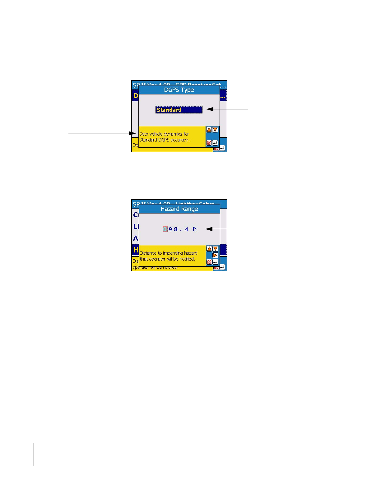
Hazard Range ....................................................................................................................38
About the Real-Time Guidance Process .......................................................................39
Starting Real-Time Guidance .....................................................................................39
The Real-Time View Page ..........................................................................................39
SmartPad II View Page Buttons .................................................................................41
Real-Time View Options ......................................................................................42
Solid View ............................................................................................................42
Spray Boom View .................................................................................................42
Zoom Pan Mode ....................................................................................................43
North Up View ......................................................................................................44
COG View ............................................................................................................44
Guidance Application Modes .........................................................................................45
The Parallel Guidance Mode .........................................................................................46
Turning On Applied Swath ...............................................................................................48
The Curved A-B Guidance Mode ..................................................................................49
The Curved Guidance Mode ..........................................................................................51
Applying Multiple Headland Circuits .........................................................................51
Switching from One Guidance Mode to Another .......................................................54
The Circle Pivot Guidance Mode ..................................................................................56
Marking Point A .........................................................................................................56
Marking Point B ..........................................................................................................57
Circle Guideline Guidance ..........................................................................................57
Page 6

SmartPad II
Software Version 4.03
Viewing Data in Fieldware Map Manager .................................................................61
Lightbar Curved Guidance Graphics ...........................................................................62
A Note on Driving Curved Guidance .........................................................................62
Applied Area Detection ..................................................................................................63
Creating a Field Boundary .............................................................................................65
Mapping Points and Hazards ........................................................................................68
Hazard Detection ............................................................................................................72
Lightbar Index ................................................................................................................74
Swath XL / GuideLine Lightbar .................................................................................75
CenterLine Lightbar ..........................................................................................................78
Chapter 3 Notes ...............................................................................................................81
Chapter 4 - Waypoint Navigation ...............................................................1
About the Nav 2 Point Application .................................................................................2
Getting to the Nav 2 Point Application ........................................................................2
Setting Up the Nav 2 Point Application ..........................................................................4
Lightbar Setup ..................................................................................................................5
Use Lightbar .......................................................................................................................6
LED Brightness ...................................................................................................................7
Alarm ..................................................................................................................................8
Alarm Range .......................................................................................................................9
Display Message ...............................................................................................................10
Antenna Setup .................................................................................................................11
Offset Direction ................................................................................................................13
Offset Distance .................................................................................................................14
Data Setup .......................................................................................................................15
Point/Grid File ..................................................................................................................17
Boundary ...........................................................................................................................18
Background .......................................................................................................................19
Sample Number ................................................................................................................20
Sample Name ....................................................................................................................21
About Nav 2 Point Real-Time Navigation ....................................................................22
The Real-Time View Page ................................................................................................24
Nav2Point Real time View Buttons ............................................................................25
Real-Time View Options ............................................................................................26
North Up View ......................................................................................................26
COG View ............................................................................................................26
Nav 2 Point Real-Time Scenarios ..................................................................................27
Mapping a Field Boundary .........................................................................................27
Table of Contents
Page 7

Dropping a Sample Point ..................................................................................................30
Detecting Nearness to a Sample Point ..................................................................31
Adding the Start Navigation Button .....................................................................32
Navigating to Points ..........................................................................................................33
Editing or Deleting a Sample Point ..................................................................................37
Editing a Sample Point .........................................................................................37
Deleting a Sample Point .......................................................................................38
Lightbar Index ................................................................................................................40
Chapter 4 Notes ...............................................................................................................42
Chapter 5 - Field Mapping .......................................................................... 1
About the Mapper Application ........................................................................................2
Getting to the Mapper Application ...............................................................................2
Setting Up the Mapper Application ................................................................................3
Data Setup .........................................................................................................................4
Boundary .............................................................................................................................6
Antenna Setup ...................................................................................................................7
Offset Direction ..................................................................................................................9
Offset Distance .................................................................................................................10
About Mapper Real-Time Mapping .............................................................................11
The Real-Time View Page ................................................................................................13
Real-Time View Buttons ..................................................................................................14
Real-Time View Options ..................................................................................................15
North Up View ......................................................................................................15
COG View ............................................................................................................15
Creating a Field Boundary .............................................................................................16
Mapping Points and Hazards ........................................................................................17
Marking a Hazard .............................................................................................................19
Mapper Application Modes ...........................................................................................20
The Polygon Stream Mode .............................................................................................21
The Polygon Mark Mode ...............................................................................................22
The Polyline Stream Mode .............................................................................................23
The Polyline Mark Mode ...............................................................................................24
Chapter 5 Notes ...............................................................................................................25
Page 8

SmartPad II
Software Version 4.03
Table of Contents
Page 9

Chapter 1 - Introduction
Simple, straight forward guidance and mapping.
Software Version 4.03
Midwest Technologies Inc.
Vehicle Guidance and Mapping Software
Page 10

SmartPad II
Software Version 4.03
Welcome to SmartPad II
SmartPad II is a GPS driven swath guidance and mapping system. The SmartPad II system comes complete
with Lightbar, Interface cable and SmartPad II.
Guidance
The SmartPad II Guidance software allows an operator to perform product application while receiving guidance information from the Lightbar. The operator can select between four different guidance modes, Parallel, Curved, Curved A-B, and Center Pivot. Using SmartPad II you can map field boundaries while applying
products around the headlands, perform guidance in most any weather and visibility conditions. SmartPad II
utilizes the Lightbar as a visual aide, minimizing operator fatigue by reducing the need to constantly watch a
display. The Lightbar can display cross track error, swath number as well as several other useful text messages such as a warning when the vehicle enters a previously applied area. The SmartPad II system allows
you to create and view an as applied map of your field and vehicle swath trajectory while applying product
to the field. Application Reports can be generated in Fieldware Map Manager software.
Using SmartPad II is simple and intuitive. The Parallel and Curved A-B mode allows the operator to drive
the initial guide line, marking the start (A) point and the end (B) point. Once the initial line (A-B) has been
established, the operator can drive parallel or curved lines with respect to this line. The operator can at any
time during guidance create additional initial A-B guidelines in any orientation. This allows the operator to
employ parallel and curved swathing in as many suitable directions as required within a single field. In the
Curved mode; the operator can make several passes around the field headlands and receive curved guidance
information via the Lightbar, once the multiple headland passes are completed the operator has the option to
switch to Parallel, Curved A-B, or Circle Pivot mode or remain in curved guidance mode. The Circle Pivot
mode allows the user to drive an initial circle pass, marking the start (A) point and the end (B) point. This
establishes the initial circle guideline, the operator can now drive parallel circle lines with respect to the initial circle guideline. The SmartPad II software will automatically sense when the vehicle is departing one
line and approaching a new line and begin guiding the operator to, and along, the new line. This eliminates
the need to manually notify the software that you want to move to a new guideline.
Nav2Point
The SmartPad II Waypoint Navigation (Nav2Pt) software allows the operator to navigate to specific locations in and around a field. The Nav2Pt program allows you to navigate to specific pre-determined point
locations or to more generalized areas of a field based on various types of background data such as soil sample point maps. Once at a desired location you can add that location as a sample point and assign a point
number and name. The primary use of the Nav2Pt program will be for soil sampling. Sample points and
grids created in the Fieldware - Tools Form a Sampling Pattern program can be imported into this program.
When used in conjunction with the Lightbar, Nav2PT application can guide the operator to desired point
locations using the lightbar as a visual aide.
Mapper
The SmartPad II Mapper application allows the operator to map field boundaries, weed patches, insect infestation, ponds, tile lines, as well as any other feature important to field application. These features can be
mapped as points, lines, or polygons. The data collected in Mapper is stored in a file that can be used as a
background map when using the Guidance or Nav2Point application.
1-2 Chapter 1 - Introduction
Welcome to SmartPad II
Page 11

SmartPad II
Software Version 4.03
Data collected using SmartPad II software can be viewed, edited or converted into other files formats using
the Fieldware - MapManager software, or imported directly into several standard Agricultural GIS packages
on the market today. This User’s Guide describes how to install, configure and use the SmartPad II product.
For technical information regarding other MID-TECH products such as the MID-TECH line of GPS receivers and rate controllers, please refer to the appropriate MID-TECH user’s guide.
We recommended that you read this user’s guide prior to using the SmartPad II product. This user’s guide
contains the following:
• Chapter 1, Introduction to SmartPad II, contains a product overview and instructions for installing the
SmartPad II hardware.
• Chapter 2, Getting Started, gives instructions on how to setup and configure the SmartPad II and software.
• Chapter 3, Real-Time Operation, describes SmartPad II real-time guidance and mapping.
• Chapter 4, Waypoint Navigation, describes SmartPad II real-time Nav2Point.
• Chapter 5, Mapper, describes SmartPad II real-time mapping options.
Using the optional CompactFlash data card, SmartPad II can also create and save to the card a vehicle application trajectory record file (.RCD). The CompactFlash data card is required to store any data, no data is
stored internally to the SmartPad II. You can also map points and hazards during the real-time guidance process. Any data saved to the CompactFlash card can be viewed and printed using MID-TECH FieldwareTools software included as an option with SmartPad II. If a field boundary is not available one can be created
based on the boom width while the operator is spraying or driving the perimeter of the field. Total field area,
in Acres or Hectares, is calculated, as well as total area applied. If a field boundary already exists, possibly
created using the MID-TECH Fieldware - Field Mapping application, it can be viewed in the background.
Chapter 1 - Introduction 1-3
Welcome to SmartPad II
Page 12

SmartPad II
Software Version 4.03
What’s New in Version 4.03
There is one new application and several new features released in Version 4.03.
General
• Touch scr ee n
• Uses Compact Flash storage cards
• Uses existing Swath XL and Guideline interface and lightbar
• Software now called “Fieldware for the Smart Pad II”
• Pop up keyboard for touch screen entry of names and values
• View and delete files from card
• Adjust brightness and backlight with keys on keypad
• Added “Pan” feature allowing users to move around and zoom in on the map in real time with
key strokes
• Touching objects in real time brings up the object’s info
• E-Dif ready
• Added a “GPS Logger” application under Tools to log raw GGA output from a receiver
• Communication with the CenterLine lightbar for Mapping and Data Storage
• Tilt Sensor ready
Nav-2-Point
• View GMF files as background
• Show BND files as background
• Last visited sample point is “remembered” eliminating need to scroll to next sample number
Guidance
• As Applied data can now be viewed in Solid view or Boom Pattern view
• Curved AB now a guidance type
• Guidance Type now selected in real time menu
• Distance to next pass information displayed on lightbar
• Verification before creating a new guideline when one already exists
• Can now collect where-applied data without lightbar connected
• Last guidance type selected now remembered on exit and for next job
New Application "Mapper"
• Mapper now added as an application
• Allows mapping of points, hazards, lines, polygons and boundaries
1-4 Chapter 1 - Introduction
Welcome to SmartPad II
Page 13
SmartPad II
Software Version 4.03
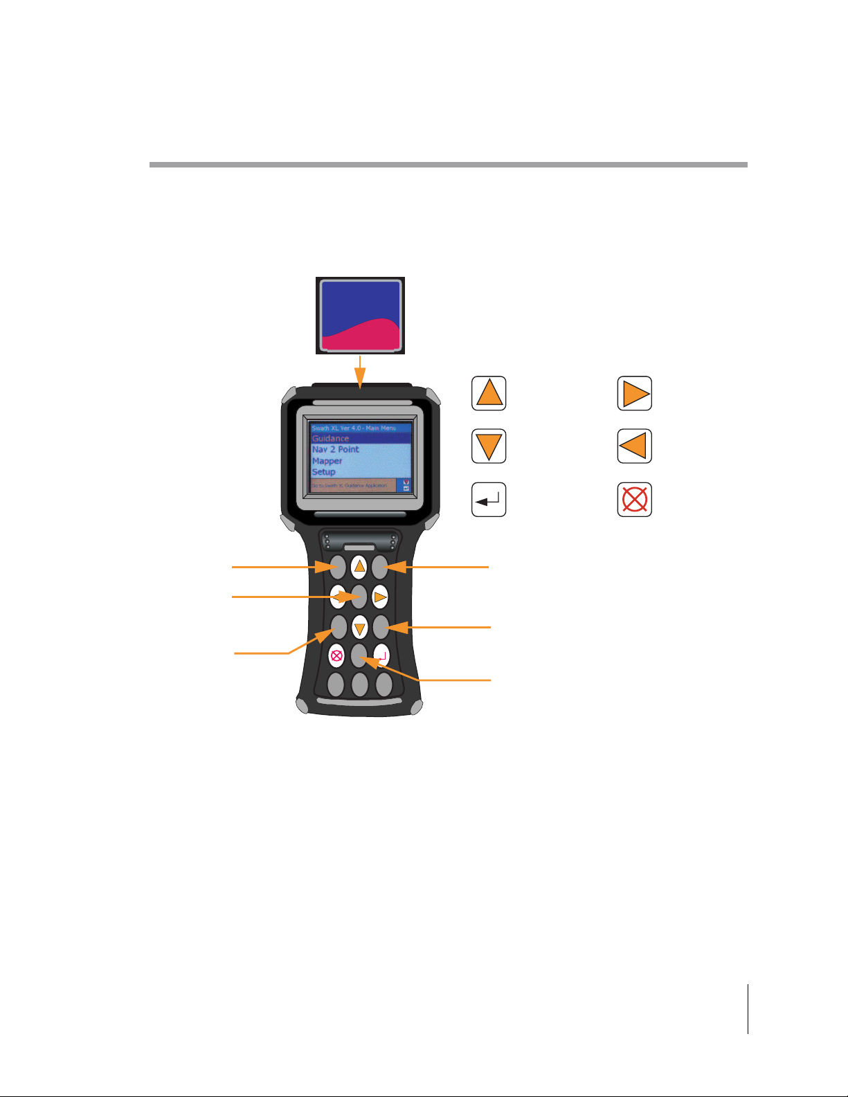
SpartPad II Handheld Button Functions
One of the new features on the SmartPad II is the ability to change the backlight and lightbar brightness On
The Go! Please review Figure 1-1 to see which buttons control the screen and backlight.
COMPACTFLASH CARD 256MB
CompactFlash
MB
256
San Disk
BACKLIGHT
DIM
CENTER
SCREEN
LIGHTBAR
DIM
SHIFT
CTRL
UP ARROW
DOWN ARROW
ENTER
2ND
CHG
LOW
BAT
CAPS
ALT
BACKLIGHT
RIGHT ARROW
LEFT ARROW
EXIT
BRIGHT
LIGHTBAR
BRIGHT
BACKLIGHT
ON / OFF
Figure 1-1:
Chapter 1 - Introduction 1-5
SpartPad II Handheld Button Functions
Page 14

SmartPad II
Software Version 4.03
SmartPad II Installation Instructions
Unpacking Your System
Open the shipping box and examine the contents for any signs of damage. Please notify the shipper and
MID-TECH Customer Support of any damage to the shipping box or its contents. Make sure you have
received all items that you purchased with the SmartPad II System. Contents may vary according to what
you ordered. Table 1-1 lists the standard components that should arrive with your SmartPad II system. Please
keep your invoice and original shipping box. If you need to return the Lightbar, it must be returned in the
original shipping box.
Swath XL / GuideLine Kits Part # Quantity
SmartPad II handheld 75-30005 1
SmartPad II to Swath XL or GuideLine
Interface Cable
SmartPad II Swath XL / GuideLine
Lightbar with Mounting Bracket
78-05050 1
MT 78-50058
TJ 78-50075
1
Table 1-1: SmartPad II Swath XL / GuideLine Components
CenterLine Kits Part # Quantity
SmartPad II handheld 75-30005 1
SmartPad II to Centerline
Interface Cable
SmartPad II CenterLine Lightbar with
Mounting Bracket
78-05427 1
MT 78-50112
TJ 78-50111
1
Table 1-2: SmartPad II CenterLine Components
Installing Your System
It is important that you setup and install the SmartPad II hardware properly. Incorrect setup or poor installation may result in intermittent and erratic operation of both the SmartPad II hardware and software. This
User’s Guide does not cover GPS receiver setup and operation. You should review the appropriate operators
manual for installation instructions. We recommend connecting all hardware components prior to permanently installing each component in the vehicle. Once you have concluded that all components are interfaced
and running properly, you should disconnect everything and install them in the vehicle.It is very important
that you choose the installation location carefully, making sure that all cables and connections are easily
reached and there is no excess strain on any connections. A clean and proper installation will ensure hours
and hours of trouble free operation.
GPS Receiver
Please review your GPS receiver User’s Guide for specific installation instructions. Always check each cable
length prior to permanently installing the receiver. Make sure the serial cable from the GPS receiver to the
SmartPad II Interface cable is not crimped or damaged and is placed so that it will not get caught inadvertently by a foot or door.
1-6 Chapter 1 - Introduction
SmartPad II Installation Instructions
Page 15
SmartPad II
Software Version 4.03
GPS Antenna
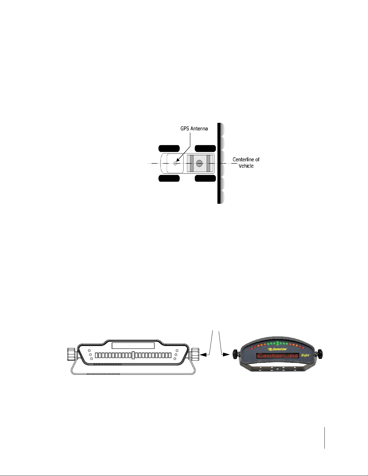
Care should be taken as to where you locate the D-GPS antenna. The most accurate D-GPS system in the
world is of no value if the antenna is located incorrectly. For any MID-TECH application employing guidance, the GPS antenna should be located along the long axis center line of the vehicle. If the vehicle long
axis center line and the center of the spray boom are not the same, i.e. the boom is not mounted to match the
center of the vehicle, then the antenna should be mounted in a location on the vehicle that matches the center
of the spray boom.
Figure 1-2: Mounting the GPS Antenna
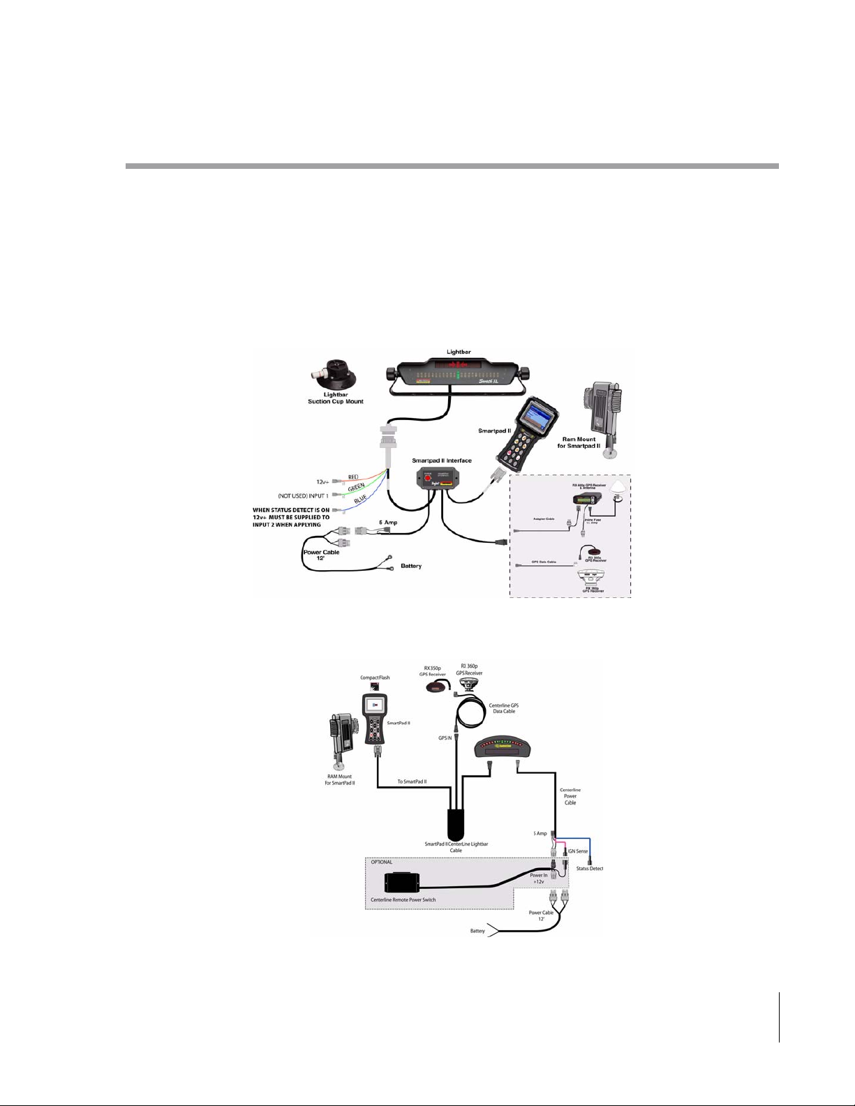
Lightbar
The Lightbar should be located with in the operators field of view while under normal driving conditions.
The Lightbar can be mounted on the vehicle cab dash or ceiling. Interior installation is recommended. The
Lightbar is weather proof and can be mounted to the exterior of a vehicle. Exterior mounting may require
additional lengths of cable, measure this distance prior to permanent installation. Lightbar extension cables
are available through MID-TECH or your MID-TECH distributor. For in cab installation, minimize the head
movement required by the operator to view the Lightbar. When the Lightbar is installed in a location that
requires minimum or no effort to view, operator fatigue is greatly reduced. Use the two knobs on either end
of the Lightbar to adjust the tilt, see Figure 1-3.
Knobs for tilt adjustment
Figure 1-3: Lightbar
Chapter 1 - Introduction 1-7
SmartPad II Installation Instructions
Page 16
SmartPad II
Software Version 4.03
SmartPad II and Interface Cable
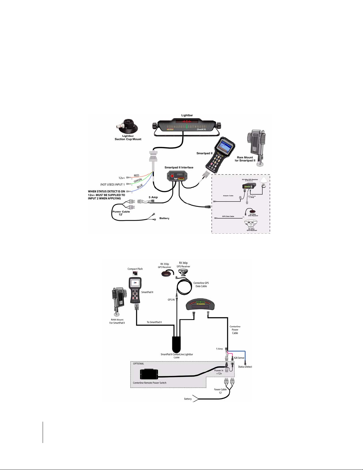
The SmartPad II and Interface cable should be located in the cab so that the operator can easily reach, view
and operate the system. See Figure 1-4 and Figure 1-5 for instruction on how to connect the Lightbar and
SmartPad II to the interface cable. Make sure the interface cables are not under any excess strain, can not be
closed in a cab door or window, or stepped on by the operator. We recommended that the interface box be
mounted within arms reach of the operator and out of harms way.
Figure 1-4: Connecting SmartPad II Swath XL / GuideLine Components
Figure 1-5: Connecting SmartPad II CenterLine Components
1-8 Chapter 1 - Introduction
SmartPad II Installation Instructions
Page 17

Software Version 4.03
System Specifications and Requirements
Lightbar
• ABS / Polycarbonate alloy construction,
• Molded cables with weatherproof connectors,
• High-lumen red, yellow and green LEDs,
• 8 character, high-intensity alpha-numeric LED display.
Interface Cables
• 12 V DC power,
• Reverse polarity and high / low voltage protection,
• Status detection leads for boom master on/off,
• Additional cables lengths available for increased mounting capabilities.
SmartPad II
SmartPad II
• VGA - TFT (Touchscreen) with adjustable backlight,
• Sealed membrane keypad,
• Internal alarm,
• Dimensions: 4.75" W x 9.84" H x 1.83" D (120.7 mm x 250 mm x 46.5 mm),
• Weight: 23 Oz. (652 g.),
• OS: Windows CE.Net 4.2
GPS Receiver Compatibility
The SmartPad II product does not include a GPS receiver. SmartPad II is compatible with any differentially
corrected, sub-meter GPS (D-GPS) receiver which outputs NMEA 0183 data at 2Hz or greater. MID-TECH
recommends the MID-TECH Rx-350p, Rx-360p or Rx400p DGPS receiver for the SmartPad II product.
Optional CompactFlash Storage Card
• SanDisk Standard Grade 128MB CompactFlash
MID-TECH can not guarantee data integrity if the optional SanDisk 128MB CompactFlash storage card is
not used with the SmartPad II system. Not all CompactFlash cards are created equal. If you choose to use a
CompactFlash card other than the recommended card option; MID-TECH will not be held responsible for
lost data, product malfunction or card incompatibility. MID-TECH will not make any hardware modifications to the SmartPad II product to accommodate any non-compatible CompactFlash cards.
Chapter 1 - Introduction 1-9
System Specifications and Requirements
Page 18
SmartPad II
Software Version 4.03
CompactFlash Card Instructions
Inserting the CompactFlash Card
The following instructions describe the basic procedure for inserting the optional 128MB CompactFlash
Data card into the SmartPad II:
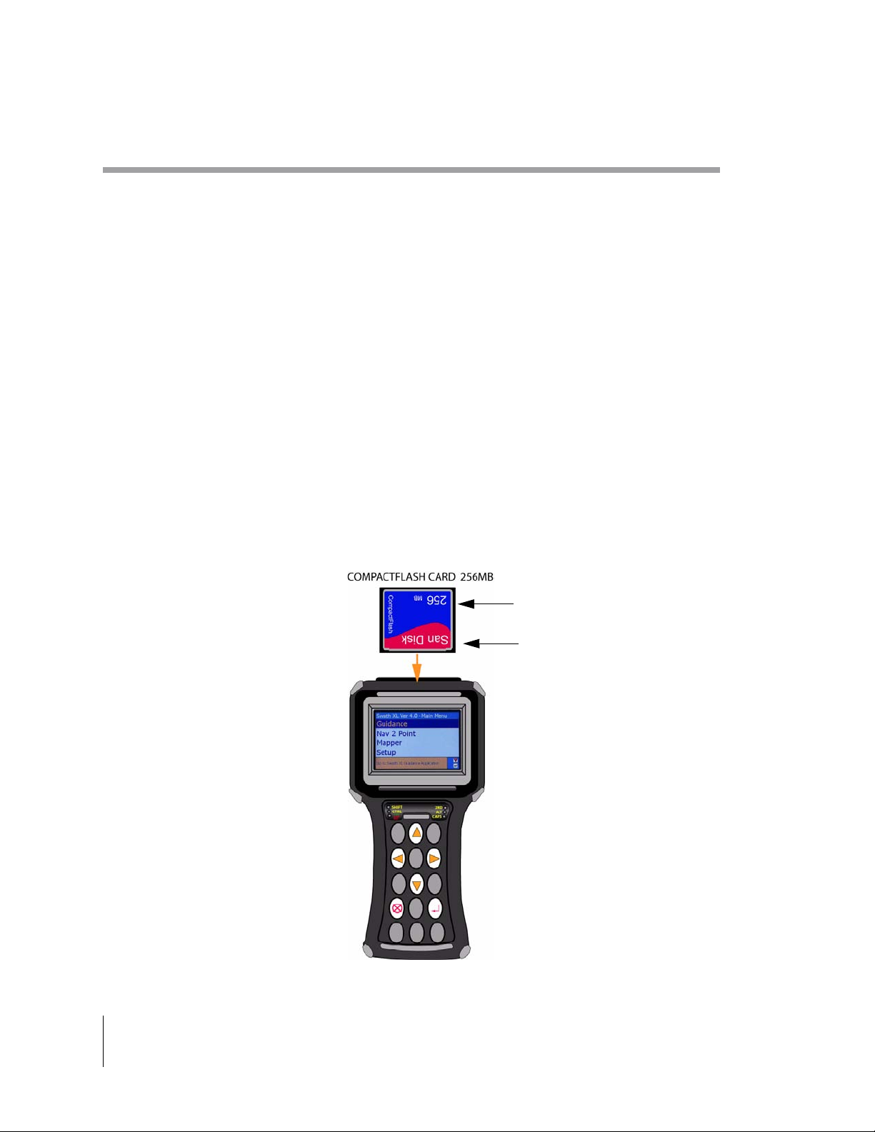
• With power off, locate the CompactFlash card socket on the top of the SmartPad II, see Figure 1-6.
• Insert the CompactFlash card into the CompactFlash card socket. Make sure that the CompactFlash card
logo is facing out. Slide the card along the guide slots until it makes contact with the SmartPad II expansion socket.
• The card will slide freely until it reaches the pins on the SmartPad II’s expansion socket, at which point,
you will feel some resistance.
• At this point, you should feel the card settle onto the expansion socket pins. Only a slight amount of
force is required to seat the card into the socket.
• Once you are certain the card is properly aligned with the SmartPad II expansion socket, insert the card
slightly beyond the resistance point to ensure it is fully seated into the socket. DO NOT FORCE THE
CARD.
CompactFlash
Flash Data
Card Logo
Figure 1-6: Inserting the CompactFlash Card
1-10 Chapter 1 - Introduction
CompactFlash Card Instructions
Page 19

SmartPad II
Software Version 4.03
Storing Data on the CompactFlash Card
If you purchase the optional CompactFlash card with the SmartPad II product, you will be able to store As
Applied, boundary and point data to the card. The CompactFlash card must be inserted into the SmartPad II
card slot during the real-time guidance process. No data is stored internal to the SmartPad II.
In order for the SmartPad II software to recognize the CompactFlash card, the card must be inserted into the
SmartPad II prior to turning the unit on.
All data written to the CompactFlash card is stored at the root directory of the card. If you choose to view
existing data such as a previously mapped field boundary, the boundary file or any other compatible file type
(.RCD, GMF and.BND) must reside in the root directory of the CompactFlash card. If you create a folder or
directory on the CompactFlash card and store data it that folder, the SmartPad II software will not be able to
access that data.
Chapter 1 - Introduction 1-11
CompactFlash Card Instructions
Page 20

SmartPad II
Software Version 4.03
Fieldware/SmartPad II File Types
The SmartPad II software can store and view three different types of files, GMF, RCD and BND, all
described below in more detail. These file types are also compatible with the MID-TECH Fieldware software suite. That means data collected using the SmartPad II product can also be used in the Fieldware software suite. You can also use any RCD, BND or GMF file that was created using the Fieldware software suite
with the SmartPad II product. As an example, a field boundary (BND) created using Fieldware - Field Mapping software can be viewed in the SmartPad II software. All data collected using SmartPad II can be viewed
and printed using the Fieldware - Tools Map Manager program.
RCD
The RCD (Record) file type will contain a record of a product application created using SmartPad II, Fieldware-Parallel Swath Guidance and Fieldware-ARM. The contents of the RCD file will be the vehicle spray
trajectory and any controller feed back information that is supplied to the Fieldware software. SmartPad II
software does not record any controller feedback. No mapping attribute data will be stored in the record file.
Any attribute mapping done in applications that use the RCD file will be stored in a GMF file.
The last guideline used prior to exiting out of the SmartPad II software will be saved. If RCD data is not
stored to the CompactFlash card no guideline information will be saved.
MID-TECH software products that can create or view an RCD file are:
• SmartPad II,
• Fieldware-Parallel Swath Guidance,
•Fieldware-ARM,
• Fieldware-Tools Map Manager
GMF
The GMF (General Map File) file type encompasses all data collected that is not specific to any of the other
file type themes. Any general attribute/feature mapping such as weed boundaries will be stored in this file
type. All applications that allow attribute mapping will use a GMF file to store this data. As an example, the
SmartPad II software will allow the user to map a limited number of field attributes such as points and hazards, this data will not be written to the RCD file, instead this data will be written to a user selected GMF
file. By moving all additional attribute data out of the application specific file and into a GMF file we allow
the user to append additional data at a later date by using Fieldware - Field Mapping or Map Manager or any
other application that accepts a GMF file. Applications that will provide attribute mapping capabilities and
therefore use a GMF file are as follows:
• SmartPad II,
• Fieldware-Field Mapping,
• Fieldware-Parallel Swath Guidance,
•Fieldware-ARM,
• Fieldware-Sample and Waypoint Navigation,
• Fieldware-Tools Map Manager,
• Fieldware-Tools Form Grid.
1-12 Chapter 1 - Introduction
Fieldware/SmartPad II File Types
Page 21

SmartPad II
Software Version 4.03
BND
The primary purpose of the BND file is to contain the boundary data for a particular field. Perimeter data
stored in a BND file can be viewed as a background map in several of the other Fieldware software applications. Boundary files can be created and appended to in SmartPad II, Fieldware-Mapper, Fieldware-Guide
and Fieldware-ARM applications. The BND file structure is identical to the GMF file structure, the BND
allows us to rapidly locate the boundary data for a particular field with in the client, farm filed directory
structure. SmartPad II does not utilized the Client Farm and Field directory structure. MID-TECH software
applications that utilize a BND file are:
• SmartPad II,
• Fieldware-Field Mapping,
• Fieldware-Parallel Swath Guidance,
•Fieldware-ARM,
• Fieldware-Sample and Waypoint Navigation,
• Fieldware-Tools Map Manager,
• Fieldware-Tools Form Grid.
GLN
The Guideline (GLN) file contains the guideline information created during the swathing or application process. This file can be automatically named to match the RCD file name, or can be custom named. The GLN
file can be used year after year in the same field, this eliminates the need to mark A and B points each time
you use the SmartPad II in the same field. MID-TECH software applications that utilize a GLN file are:
• SmartPad II,
• Fieldware-Parallel Swath Guidance,
•Fieldware-ARM,
• Fieldware-Tools Map Manager.
Chapter 1 - Introduction 1-13
Fieldware/SmartPad II File Types
Page 22

SmartPad II
Software Version 4.03
Chapter 1 Notes
1-14 Chapter 1 - Introduction
Chapter 1 Notes
Page 23

Chapter 2 - Software Overview
An introduction on how to use SmartPad II software.
Software Version 4.03
Midwest Technologies Inc.
Vehicle Guidance and Mapping Software
Page 24
Fieldware for Smartpad II
Software Version 4.03
SmartPad II Software Overview
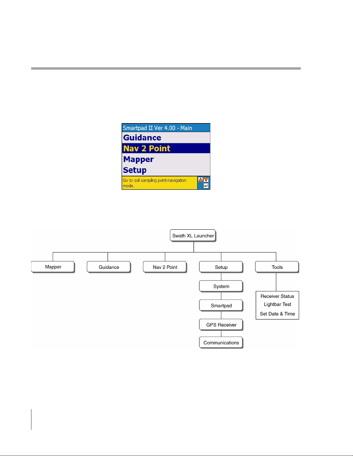
The SmartPad II software suite is made up of a Main Launcher and three software applications (programs), Guidance,
Nav2Point and Mapper. Each application can be broken down into two main components, Setup and Real-Time Mapping. Each of these components are described in more detail in following chapters. Figure 2-11 shows a flow diagram
of the SmartPad II software suite. All menu and menu items can be accessed and changed using the touchscreen or
the six keys located on the SmartPad II. For more description on how to use these six keys see “Operating SmartPad
II Software” on page 2-3.
The first time you run the SmartPad II software you may need to set a few system settings such as Date and Time
Zone, Units, SmartPad II settings and possibly Language, to configure the SmartPad II software suite the way you
prefer it. See “First Time Setup Process” on page 2-7 for more detail on setting up SmartPad II for the first time.
SmartPad II Main Launcher
Once the unit has powered up a SmartPad II splash screen will briefly appear, displaying the version number of the
software you have installed on the SmartPad II. The Main Launcher Menu page follows the splash screen, Figure 2-1.
The Main Launcher is where you can pick an application to run, either Guidance, Nav2Pt, or Mapper; System Settings and Tools are also located in the Main Launcher page. The Tools component of the Main Launcher contains several diagnostic tools that may help trouble-shoot problems with your GPS receiver and lightbar, see “SmartPad II
Tools” on page 2-24 for more details. For more information on the Main Launcher see “SmartPad II Main Launcher”
on page 2-8.
Figure 2-1: The SmartPad II Main Launcher Page
2-2 Chapter 2 - Software Overview
SmartPad II Software Overview
Page 25
Fieldware for Smartpad II
Software Version 4.03
Operating SmartPad II Software
The SmartPad II software was designed to be both easy and intuitive to use. Once an initial setup process is completed, starting up and running a SmartPad II software application can require as few as three key-strokes. The rest of
this section will describe the SmartPad II software and how to operate it. Reading the rest of this section is highly recommended.
SmartPad II Keys
There are six keys located on the SmartPad II front panel. The entire SmartPad II suite of software can be operated
using this key set.
The Arrow Keys
The four arrow keys are used to navigate between the SmartPad II menu pages, highlight menu items, and scroll
through input options in most all dialog boxes.
The Enter Key
The Enter key is typically used to enter a new menu page item and accept a dialog box value or setting.
The Exit Key
The escape key is used to return back to a previous menu page or exit out of a menu item or dialog box without affecting any of the current settings.
Chapter 2 - Software Overview 2-3
SmartPad II Software Overview
Page 26
Fieldware for Smartpad II
Software Version 4.03
Screen Selection
Touch Screen
To make a selection use a stylus and single tap the screen on the desired menu.
Manual Selection
Items can only be selected when highlighted. Use the Up and Down arrows to highlight the desired selection.
Press Enter to select.
Data Entry
On-Screen Keyboard
Select the desired menu to be changed. Select the Keyboard icon to bring up the on screen keyboard. This icon
will appear is the upper left corner of the screen only when text can be entered. Select the desired character using a
stylus and press Enter to accept.
Manual Entry
Select the desired menu to be changed, and use the Up and Down arrows to change the character. Use the Left
and Right arrows to advance to the next character. Press Enter to accept.
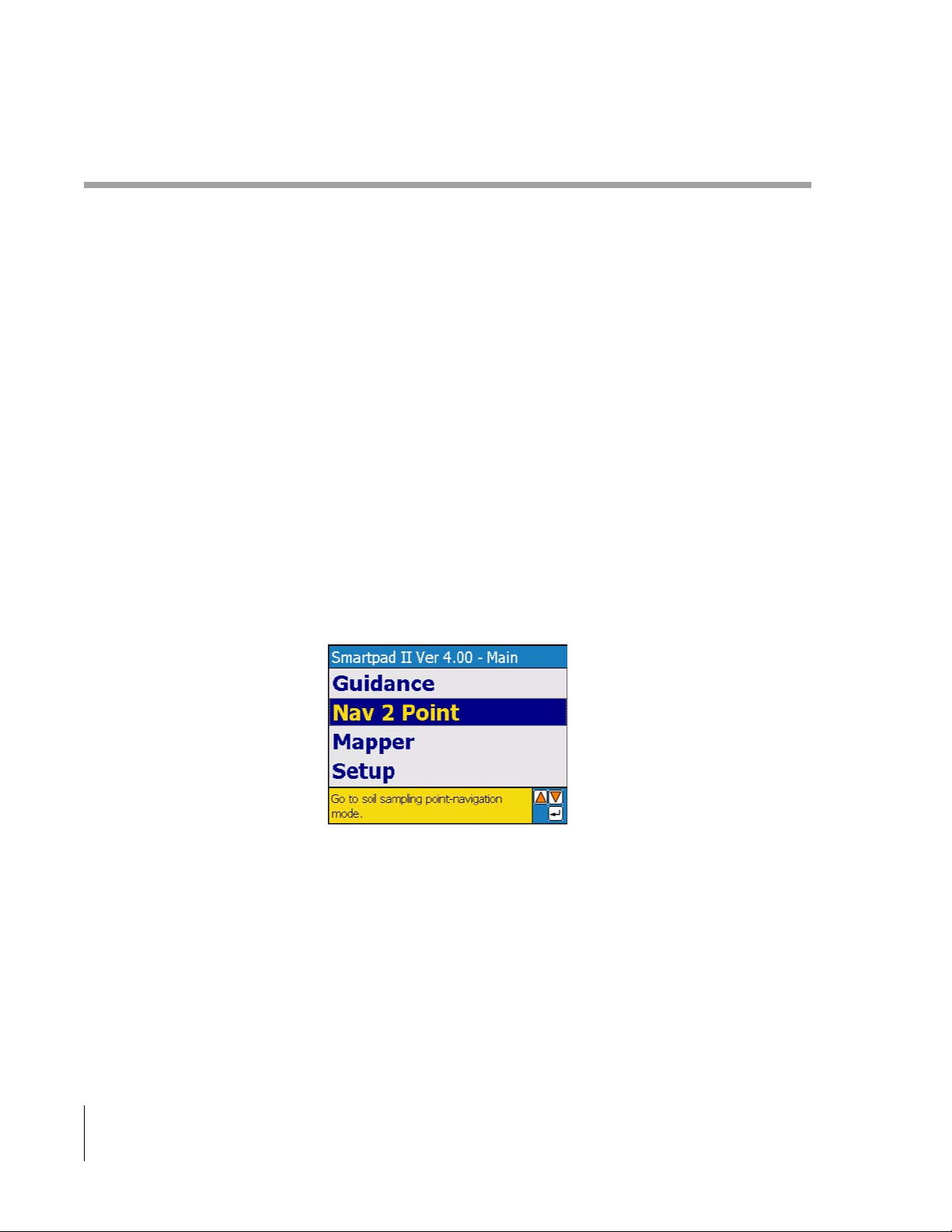
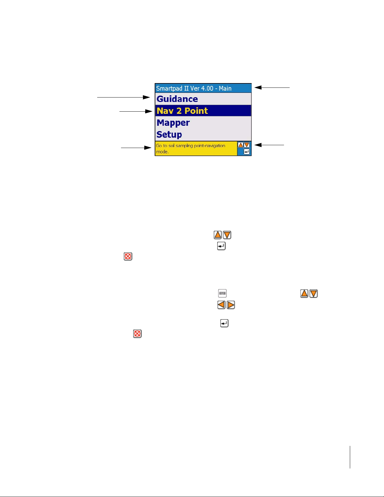
Menu Pages
Figure 2-2 shows a typical menu page containing several menu items. To select a menu item, highlight the item using
the keys. To enter a highlighted menu item use the key. To return to the previous menu page press the
key. In Figure 2-2 the current menu page is the Setup Menu, to move back to the Main Menu page, simply press the
Escape key, .
Key Code Box
On each menu page and dialog box there is a key code box, always located in the lower right corner. The purpose of
the key code box is to inform the user which keys can be used based on the highlighted menu item in a menu page, or
value setting in a dialog box. The key code box in Figure 2-2 informs the user that based on the highlighted menu
item, Nav 2 Point, they can move up and down in the menu page using the keys; enter the Nav 2 Point menu
item using the key or return to the previous menu page using the key. The left and right arrow keys are not
displayed in the key code box shown in Figure 2-2 because they have no purpose in that particular menu page.
Info Bar
Located at the bottom of every menu page and dialog box is an Info Bar. The purpose of the Info Bar is to provide a
brief description of the highlighted menu item or current setting displayed in a dialog box.
2-4 Chapter 2 - Software Overview
SmartPad II Software Overview
Page 27
.
Menu Items
Highlighted menu item
using the up and down
arrow keys
Fieldware for Smartpad II
Software Version 4.03
Current menu page
name. (Setup Menu)
Info Bar displaying
brief description of the
highlighted menu item.
Key code box showing
which keys are available
for use.
Figure 2-2: Menu Page Example
Dialog Boxes
The SmartPad II software uses dialog boxes for entering or selecting settings and values associated with each menu
item. There are two types of dialog boxes a Pick dialog box and an Alpha-Numeric dialog box. Notice that dialog
boxes also contain an Info Bar and a Key Code box.
Figure 2-3 shows an example of a Pick dialog box. A Pick dialog box allows the user to select from a list of existing
settings or values. Pick dialog settings are displayed using the keys, once the desired setting is displayed in
the dialog box, the setting is accepted or entered by pressing the key, this will also exit from the dialog and return
to the previous menu. The key allows the user to exit the dialog box without changing the setting.
Figure 2-4 shows an example of an Alpha-Numeric dialog box. This type of dialog box is used when the user is
required to enter a particular value such as a distance or a name. The complete value is made up of individual dialog
cells. In Figure 2-4, the final value is 22.0 feet and the current or highlighted cell is the 0. To enter 22.0 ft., the user
can use the on-screen keyboard by selecting the keyboard button or by selecting a 2 using the keys until a
2 was displayed. Next the user moves to the next cell, using the keys and selects another 2 using the same
method as the first 2. Finally the user moves to the decimal location and selects a 0. To accept the entire 22.0 ft. value
and return to the previous menu page, the user simply presses the key. The user can exit the dialog without chang-
ing the setting by pressing the key.
Chapter 2 - Software Overview 2-5
SmartPad II Software Overview
Page 28
Fieldware for Smartpad II
Software Version 4.03
Description of the displayed
setting.
Current setting displayed.
Figure 2-3: Pick Dialog Box Example
Dialog cell with current
value displayed.
Figure 2-4: Alpha-Numeric Dialog Box Example
2-6 Chapter 2 - Software Overview
SmartPad II Software Overview
Page 29
Fieldware for Smartpad II
Software Version 4.03
First Time Setup Process
The first time you start up the SmartPad II, you should also make sure that the current date and time are set correctly,
see “Set Date and Time” on page 2-29 for more details.
Power Unit On
Connect the SmartPad II to the SmartPad II Interface Cable, see Figure 2-5, and apply 12 VDC power. It is not necessary to have the Lightbar or GPS receiver connected and running to change any of the settings. Power the unit up by
pressing the On switch.
Figure 2-5: Connecting SmartPad II to Swath XL / GuideLine Interface Cable
Figure 2-6: Connecting SmartPad II to CenterLine Interface Cable
Chapter 2 - Software Overview 2-7
First Time Setup Process
Page 30
Fieldware for Smartpad II
Software Version 4.03
SmartPad II Main Launcher
The Main Launcher is the first menu page you will see after powering up the SmartPad II, Figure 2-7. This is the top
Menu page and from here you can launch an application (Guidance, Nav2Pt, or Mapper), access system level setup
parameters and run diagnostic tools and utilities. See Figure 2-8 for an overview of the entire SmartPad II software
suite. Each sub-menu is discussed in greater detail below.
Figure 2-7: The Main Launcher Menu Page
Figure 2-8: SmartPad II Software Suite Flow Diagram
2-8 Chapter 2 - Software Overview
SmartPad II Main Launcher
Page 31

Fieldware for Smartpad II
Software Version 4.03
Launching an Application
From the Main Launcher, the user can start (launch) a SmartPad II software application. In version 4.03 there are
three software applications Guidance, Nav2Pt, and Mapper. To launch an application highlight the desired application
name, using the up and down arrow keys on the smartpad keypad, and then press enter. The main application menu
will appear. Figure 2-9 shows the launch sequence for the Guidance application and Figure 2-10 shows the launch
sequence for the Nav2Pt application. The same would apply for the Mapper application.
Figure 2-9: Launching the Guidance Software Application
Figure 2-10: Launching the Nav2Pt Software Application
Chapter 2 - Software Overview 2-9
Launching an Application
Page 32

Fieldware for Smartpad II
Software Version 4.03
Main Setup
The Main Launcher Setup Menu, Figure 2-20, contains all setup parameters that are common to both Guidance,
Nav2Pt, and Mapper. Currently there are four setup menu items found in the Main Setup; System, SmartPad, GPS
Receiver and Communications, Figure 2-11 shows the flow diagram for the Main Setup.
Figure 2-11: Main Setup Flow Diagram
2-10 Chapter 2 - Software Overview
Main Setup
Page 33

Fieldware for Smartpad II
Software Version 4.03
Communications Setup
The Communications Setup menu defines the SmartPad II GPS serial port parameters. There are four menu items
associated with this menu page, Baud rate, Data Bits, Stop Bits and Parity, see Table 2-1.
NOTE: When using a CenterLine Lightbar the Communications menu will not be available because the baud rate is
hard coded when the SmartPad II detects a CenterLine lightbar.
To access the Communications menu page, highlight the Setup menu item in the Main menu page and press . This
takes you to the Setup menu page, see Figure 2-12 (right side). Within the Setup Menu the select the Communications
menu item using the arrow keys . Press to enter the Communications menu page. Once in the Communi-
cations menu page, you can change any of the Communications menu items by highlighting the desired menu item
and pressing .
Figure 2-12: Accessing the Communications Menu Page
Setting Name Default Value
Baud Rate Auto Not Recommended
Data Bits 8 Not Recommended
Stop Bits 1 Not Recommended
Parity None Not Recommended
Change at 1st
Time Start up
Table 2-1: Communication Menu Item Default Settings
Chapter 2 - Software Overview 2-11
Communications Setup
Page 34

Fieldware for Smartpad II
Software Version 4.03
Port Baud Rate
The Baud Rate menu item sets the GPS port baud rate on the SmartPad II, see Table 2-2.
To change the Baud Rate setting; highlight the Baud Rate menu item and press . The Port Baud Rate dialog box
will appear. Select the desired setting using the arrow keys , once the desired setting is selected, press to
return back to the Communications setup menu, see Figure 2-13.
Figure 2-13: The Port Baud Rate Menu Item
Setting Description
Auto Automatically determines the GPS port Baud Rate. This is the default setting.
1200 Sets the GPS serial port Baud Rate to 1200.
4800 Sets the GPS serial port Baud Rate to 4800.
9600 Sets the GPS serial port Baud Rate to 9600.
19200 Sets the GPS serial port Baud Rate to 19200.
Table 2-2: The Port Baud Rate Menu Item Settings
2-12 Chapter 2 - Software Overview
Communications Setup
Page 35

Fieldware for Smartpad II
Software Version 4.03
Port Data Bits
The Data Bits menu item sets the GPS port Data Bits on the SmartPad II, see Table 2-3.
To change the Data Bits setting; highlight the Data Bits menu item and press . The Port Data Bits dialog box will
appear. Select the desired setting using the arrow keys , once the desired setting is selected, press to return
back to the Communications setup menu, see Figure 2-14.
Figure 2-14: The Port Data Bit Menu Item
Setting Description
7 Sets the GPS serial port data bit value to 7.
8 Sets the GPS serial port data bit value to 8. This is the default setting.
Table 2-3: The Port Data Bit Menu Item Settings
Chapter 2 - Software Overview 2-13
Communications Setup
Page 36

Fieldware for Smartpad II
Software Version 4.03
Port Stop Bits
The Stop Bits menu item sets the GPS port Stop Bits on the SmartPad II. There are no options for this menu item and
therefore cannot be changed, see Figure 2-15.
Figure 2-15: The Port Stop Bit Menu Item
2-14 Chapter 2 - Software Overview
Communications Setup
Page 37

Fieldware for Smartpad II
Software Version 4.03
Port Parity
The Parity menu item sets the GPS port Parity on the SmartPad II, see Table 2-4.
To change the Parity setting; highlight the Parity menu item and press . The Port Parity dialog box will appear.
Select the desired setting using the arrow keys , once the desired setting is selected, press to return back to
the Communications setup menu, see Figure 2-16.
Figure 2-16: The Port Parity Menu Item
Setting Description
None Sets the SmartPad II GPS serial port parity to None. This is the default setting.
Odd Sets the SmartPad II GPS serial port parity to Odd.
Even Sets the SmartPad II GPS serial port parity to Even.
Table 2-4: The Port Parity Menu Item Settings
Chapter 2 - Software Overview 2-15
Communications Setup
Page 38

Fieldware for Smartpad II
Software Version 4.03
SmartPad II Setup
SmartPad II setup defines all parameters associated with the SmartPad II. There are two SmartPad II setup menu
items, Display Brightness and Display Backlight. SmartPad II Setup default values are listed in Table 2-5. These
menu items can adjusted using the buttons on the SmartPad II handheld. See Bulletin 98-01122 for button description.
The SmartPad II will default to menu settings when the unit is powered off.
To access the SmartPad II menu page, highlight the Setup menu item in the Main menu page and press . This takes
you to the Setup menu page, see Figure 2-17 (right side). With in the Setup Menu, select the SmartPad II menu item
using the arrow keys . Press to enter the SmartPad II menu page. Once in the SmartPad II menu page, you
can change any of the menu item settings by highlighting the desired menu item and pressing .
Figure 2-17: Accessing the SmartPad II Menu Page
Setting Name Default Value
Display Brightness 7 Optional
Display Backlight On Optional
Change at 1st
Time Start Up
Table 2-5: SmartPad II Menu Item Default Settings
2-16 Chapter 2 - Software Overview
Communications Setup
Page 39

Fieldware for Smartpad II
Software Version 4.03
Display Brightness
The Display Brightness setting allows you to set the SmartPad II display brightness. The available settings are 1
through 10, where 10 is the brightest setting.
To change the Display Brightness setting; highlight the Brightness menu item and press . The Display Brightness
dialog box will appear. Select the desired Brightness setting using the arrow keys , once the desired brightness
level is selected, press to return back to the SmartPad II setup menu, see Figure 2-18.
Figure 2-18: The Display Brightness Menu Item
Chapter 2 - Software Overview 2-17
Communications Setup
Page 40

Fieldware for Smartpad II
Software Version 4.03
Display Backlight
The Display Backlight setting controls the SmartPad II display backlight. This menu item can be set to On or Off.
To change the Display Backlight setting; highlight the Backlight menu item and press . The Display Backlight
dialog box will appear. Select the desired setting using the arrow keys , once the desired setting is selected,
press to return back to the SmartPad II setup menu, see Figure 2-19.
Figure 2-19: The Backlight Menu Item
Setting Description
On Turns the SmartPad II display backlight on. This is the default setting.
Off Turns the SmartPad II display backlight off.
Table 2-6: The Display Backlight Menu Item Settings
2-18 Chapter 2 - Software Overview
Communications Setup
Page 41

Fieldware for Smartpad II
Software Version 4.03
System Setup
System setup defines certain system parameters that will affect the entire SmartPad II software suite. There are two
System setup menu items, Unit and Language, see Table 2-7.
To access the System menu page, highlight the Setup menu item in the Main menu page and press . This takes you
to the Setup menu page, see Figure 2-20 (right side). Within the Setup Menu select the System menu item using the
arrow keys . Press to enter the System menu page. Once in the System menu page, you can change any of
the menu item settings by highlighting the desired menu item and pressing .
Figure 2-20: Accessing the System Menu Page
Setting Name Default Value
Unit US Optional
Language English Optional
Change at 1st
Time Start Up
Table 2-7: System Menu Item Default Settings
Chapter 2 - Software Overview 2-19
Communications Setup
Page 42

Fieldware for Smartpad II
Software Version 4.03
Unit
The Unit menu item defines the SmartPad II measurement system. There are two choices, US and Metric. The unit set
in this menu field will effect the entire SmartPad II software suite.
To change the System Unit; highlight the Unit menu item and press . The System Unit dialog box will appear.
Select the desired unit setting using the arrow keys , once the desired unit is selected, press to return back
to the System setup menu, see Figure 2-21.
Figure 2-21: The Unit Menu Item
Setting Description
US All units will be entered and displayed in Feet, Miles, Acres and US volumes. This is
the default setting.
Metric All units will be entered and displayed in Meters, Kilometers, Hectare and Metric vol-
umes.
Table 2-8: The Unit Menu Item Settings
2-20 Chapter 2 - Software Overview
Communications Setup
Page 43

Fieldware for Smartpad II
Software Version 4.03
Language
The Language menu item defines the user language that will be used through out the entire SmartPad II software
suite. All languages that are available to the SmartPad II software suite are stored in the Support folder on the PCM-
CIA Card. To change the System Language; highlight the Language menu item and press . The System Language
dialog box will appear. Select the desired language using the arrow keys , once the desired language is
selected, press to return back to the System setup menu, see Figure 2-22. You will have to power off and then
power on the SmartPad II before a change in system language can take place.
Figure 2-22: The Language Menu Item Setting
Chapter 2 - Software Overview 2-21
Communications Setup
Page 44

Fieldware for Smartpad II
Software Version 4.03
GPS Receiver
GPS Receiver setup defines DGPS Type Accuracy. GPS Receiver Setup default values are listed in Table 2-9.
To access the GPS Receiver menu page, highlight the Setup menu item in the Main menu page and press . This
takes you to the Setup menu page, see Figure 2-23 (Left side). With in the Setup Menu select the GPS Receiver menu
item using the arrow keys . Press to enter the GPS Receiver menu page. Once in the GPS Receiver menu
page, you can change any of the menu item settings by highlighting the desired menu item and pressing
Figure 2-23: Accessing the GPS Receiver Menu Page
Setting Name Default Value
DGPS Type Standard Optional
Change at 1st
Time Start Up
Table 2-9: GPS Receiver Menu Item Default Settings
2-22 Chapter 2 - Software Overview
Communications Setup
Page 45

Fieldware for Smartpad II
Software Version 4.03
DGPS Type
The DGPS Type defines the type and accuracy of the DGPS source used with your GPS Receiver. This setting defines
which set of vehicle dynamic parameters should be used in guidance and point navigation.
To change the Display Backlight setting; highlight the Backlight menu item and press . The Display Backlight
dialog box will appear. Select the desired setting using the arrow keys , once the desired setting is selected,
press to return back to the GPS Receiver setup menu, see
Figure 2-24: Setting the DGPS Type Parameter
Setting Description
Standard Sets vehicle dynamics for Standard DGPS sub-meter accuracy. DGPS sources such as
WAAS, Beacon and Satellite should use the Standard setting.
RTK Sets vehicle dynamics for Real Time Kinematics (RTK) decimeter to centimeter accu-
racy.
Table 2-10: The Display Backlight Menu Item Settings
Chapter 2 - Software Overview 2-23
Communications Setup
Page 46

Fieldware for Smartpad II
Software Version 4.03
SmartPad II Tools
SmartPad II comes with a set of hardware diagnostic tools that will come in handy when trouble shooting a GPS
receiver or lightbar. You can also set the system clock.
To access the Tools menu page, highlight the Tools menu item in the Main Launcher menu page and press . This
takes you to the Tools menu page, see Figure 2-25. Once in the Tools menu page, you can enter any of the Tools menu
items by highlighting the desired menu item and pressing .
Figure 2-25: Accessing the Tools Menu Page
2-24 Chapter 2 - Software Overview
SmartPad II Tools
Page 47

Fieldware for Smartpad II
Software Version 4.03
Receiver Status
The Receiver Status tool allows you to quickly determine if your GPS receiver is operating properly. A Status window
displays easy to understand text information about the operating status of your GPS receiver. The Serial Data Sample
windows displays the current raw position string coming from the GPS receiver. The Last Position window displays
the current position (Latitude, Longitude) in decimal degrees. The Position Rate window displays the GPS receiver
data rate and the total number of positions received.
Figure 2-26: The Receiver Status Tool
Chapter 2 - Software Overview 2-25
SmartPad II Tools
Page 48

Fieldware for Smartpad II
Software Version 4.03
GPS Logger
The GPS Logger tool is used to log and store the GPS coordinates during a session. This tool would be used to create
a.raw file that could be ran using Mid-Tech’s GPSsim program to simulate a live GPS input. The most common use of
this feature is to simulate GPS to a SmartPad II system without moving.
To use this tool select the Data Logger menu and create a Log File name see Figure 2-27. Once a name is created
select go and begin to drive. As the vehicle moves the location is being stored to the Log File. NOTE: If the operator
stops moving the systems does not stop recording GPS coordinates.
2-26 Chapter 2 - Software Overview
SmartPad II Tools
Figure 2-27: Data Logger Setup
Page 49

Fieldware for Smartpad II
Software Version 4.03
Lightbar Test
The Lightbar Test diagnostic allows the users to determine if the SmartPad II is communicating to the lightbar. The
Lightbar Test diagnostic can also be used to determine if any of the guidance LEDs or LEDs in the text display are not
working properly.
To run the lightbar test program, highlight the Lightbar Test menu item using the keys. Once highlighted
press . This will automatically start the lightbar test program. The test consists of the guidance LEDs illuminating
by color, Green first, then all Yellow and finally Reds. Once the guidance LED test cycle is complete, the text display
will illuminate in a series of blocks, this will cycle a few times. The test is completed when the text display displays
End.
Figure 2-28: Lightbar Test
Chapter 2 - Software Overview 2-27
SmartPad II Tools
Page 50

Fieldware for Smartpad II
Software Version 4.03
Delete Files
The Delete Files tool allows the operator to view and delete individual or all files stored on the CompactFlash data
card. The data card must be inserted in the SmartPad II prior to boot up (powering on).
To delete files select the Delete Files menu and then select the desired file to be delete and press enter. A warning will
appears asking if the operator is sure this file is to be deleted Figure 2-29 if accepted the file will be deleted
Figure 2-29: Delete Files from CompactFlash card using the SmartPad II
2-28 Chapter 2 - Software Overview
SmartPad II Tools
Page 51

Fieldware for Smartpad II
Software Version 4.03
Set Date and Time
You may need to set the date and time on the SmartPad II. Several features related to the SmartPad II software will
depend on the current date and time. All data file creation will be tagged with a date and time stamp. The auto-file
name feature will also use the current date to create the file name, therefore it is important that the SmartPad II date
and time are correct.
To change the current date and time settings; highlight the Set Date and Time menu item and press . The Date and
Time dialog box will appear. Enter the current date and time using the arrow keys, , once correct date
and time is entered, press to return back to the Tools setup menu, see Figure 2-30.
Figure 2-30: Setting the Date and Time
Chapter 2 - Software Overview 2-29
SmartPad II Tools
Page 52

Fieldware for Smartpad II
Software Version 4.03
Clock
The Clock program
turns your lightbar into a clock by displaying the time in the text display window on the lightbar. The time displayed
will be based on the system time.
To display time on your lightbar, highlight the Clock menu item using the keys. Once highlighted press .
This will automatically display the time on your lightbar. To exit the Clock program, press the key.
Figure 2-31: The Clock Utility
2-30 Chapter 2 - Software Overview
SmartPad II Tools
Page 53

Chapter 2 Notes
Fieldware for Smartpad II
Software Version 4.03
Chapter 2 - Software Overview 2-31
Chapter 2 Notes
Page 54

Fieldware for Smartpad II
Software Version 4.03
2-32 Chapter 2 - Software Overview
Chapter 2 Notes
Page 55

Chapter 3 - Real-Time Guidance
Mapping product application in real-time using guidance.
Software Version 4.03
Midwest Technologies Inc.
Vehicle Guidance and Mapping Software
Page 56

SmartPad II
Software Version 4.03
About the Guidance Application
Using the lightbar, the guidance function provides the operator with clear and intuitive steering assistance as well as
real-time application information. The operator can select between four different guidance modes, Parallel, Curved,
Curved A-B, and Center Pivot. Using SmartPad II you can map field boundaries while applying products around the
headlands, perform guidance in most any weather and visibility conditions. SmartPad II utilizes the Lightbar as a
visual aide, minimizing operator fatigue by reducing the need to constantly watch a display. The Lightbar can display
cross track error, swath number as well as several other useful text messages such as a warning when the vehicle
enters a previously applied area. The SmartPad II system allows you to create and view a where applied map of your
field and vehicle swath trajectory while applying product to the field. Application Reports can be generated in Fieldware Map Manager software.
Using SmartPad II is simple and intuitive. The Parallel and Curved A-B mode allows the operator to drive the initial
guide line, marking the start (A) point and the end (B) point. Once the initial line (A-B) has been established, the
operator can drive parallel or curved lines with respect to this line. The operator can at any time during guidance create additional initial A-B guidelines in any orientation. This allows the operator to employ parallel and curved swathing in as many suitable directions as required within a single field. In the Curved mode; the operator can make several
passes around the field headlands and receive curved guidance information via the Lightbar, once the multiple headland passes are completed the operator has the option to switch to Parallel mode or remain in curved guidance mode.
The Circle Pivot mode allows the user to drive an initial circle pass, marking the start (A) point and the end (B) point.
This establishes the initial circle guideline, the operator can now drive parallel circle lines with respect to the initial
circle guideline. The SmartPad II software will automatically sense when the vehicle is departing one line and
approaching a new line and begin guiding the operator to, and along, the new line. This eliminates the need to manually notify the software that you want to move to a new guideline.
Starting Guidance for the First Time
The first time you attempt to run the SmartPad II Guidance application you will need to enter the vehicle swath width.
To enter the swath width follow the steps outlined in “Swath Width” on page 3-5. You should also make sure that the
current date and time are set correctly, see Chapter 2 for more details.
Connect the SmartPad II to the SmartPad II Interface Cable, and apply 12 VDC power. It is not necessary to have the
Lightbar or GPS receiver connected and running to change the Vehicle Swath Width. Power the unit up by pressing
the On switch.
3-2 Chapter 3 - Real-Time Guidance
About the Guidance Application
Page 57

SmartPad II
Software Version 4.03
Guidance Setup
Guidance setup allows the user to set up several parameters that pertain to guidance functionality. There are five guidance related menu items, Swath Width, Look Ahead, Direction to Swath, Distance to Swath and Status Detect, see
Figure 3-2 and Table 3-1.
To access the Guidance menu page, highlight the Setup menu item in the Main menu page and press . This takes
you to the Setup menu page, see Figure 3-1. Within the Setup Menu the Guidance menu item is the first item and
should be highlighted. Press to enter the Guidance menu page. Once in the Guidance menu page, you can change
any of the Guidance menu items by highlighting the desired menu item and pressing .
Figure 3-1: Accessing the Guidance Menu Page
Figure 3-2: Guidance Setup Flow Diagram
Chapter 3 - Real-Time Guidance 3-3
Guidance Setup
Page 58

SmartPad II
Software Version 4.03
Setting Name Default Value
Swath Width 0.0 Required
Look Ahead 2.0 s Optional
Direction to Swath None Recommended
Distance to Swath 0.0 ft. Recommended
Antenna Height 9.8ft. Recommended
Status Detect Off Optional
GPS Type DGPS Recommended
GPS Data Rate 5Hz Recommended
Change at 1st
Time Start Up
Table 3-1: Guidance Menu Item Default Settings
3-4 Chapter 3 - Real-Time Guidance
Guidance Setup
Page 59

SmartPad II
Software Version 4.03
Swath Width
The guidance parameter Swath Width is the distance between guidelines. This width is typically determined by the
vehicle swath width or spread area, see Figure 3-3. Setting the swath width slightly smaller than the actual width will
reduce skips. Setting the swath width slightly larger than the actual swath width will reduce overlap.
Figure 3-3: Example of Swath Width
To change the Swath Width value; highlight the Swath Width menu item and press . The Swath Width dialog box
will appear. Enter the desired width using the arrow keys , once the desired width is entered, press
to return back to the Guidance setup menu, see Figure 3-4.
Figure 3-4: The Swath Width Menu Item
Chapter 3 - Real-Time Guidance 3-5
Guidance Setup
Page 60

SmartPad II
Software Version 4.03
Look Ahead
The Look Ahead value is the number of seconds ahead of the vehicle you would like the SmartPad II software to calculate the cross track error. Based on the vehicles speed and trajectory and this look ahead value, SmartPad II can
determine where the vehicle will be with respect to the current guideline. This setting will vary based on the vehicle
operators driving ability and preference. This value is only used with the guidance pattern Parallel. It is not used in
Headland curved guidance or the Circle Pivot pattern. A Look Ahead value that fits the operator best will result in
smoother guidance operations. Typically this value is set to 2 seconds.
To change the Look Ahead value; highlight the Look Ahead menu item and press . The Look Ahead dialog box
will appear. Enter the desired value using the arrow keys, , once the desired value is entered, press
to return back to the Guidance setup menu, see Figure 3-5
Figure 3-5: The Look Ahead Menu Item
3-6 Chapter 3 - Real-Time Guidance
Guidance Setup
Page 61

SmartPad II
Software Version 4.03
Direction to Swath
The guidance parameters, Direction to Swath and Distance to Swath, are used to define the spatial relationship
between the GPS antenna and the product delivery location. Examples of a product delivery location would be the
boom on a sprayer or the spinner box on a fertilizer spreader. The position of the swath with respect to the GPS
antenna will be used to accurately create an As Applied map. The Direction to Swath parameter defines the direction
from the GPS antenna to the delivery location, see Figure 3-6. The GPS antenna should always be mounted on the
center-line of the vehicle.
Figure 3-6: Example of Direction to Swath
To change the Direction to Swath value; highlight the Direction to Swath menu item and press . The Direction to
Swath dialog box will appear. Select the desired position value using the arrow keys , once the desired posi-
tion is selected, press to return back to the Guidance setup menu, see Figure 3-7
Figure 3-7: The Direction to Swath Menu Item
Chapter 3 - Real-Time Guidance 3-7
Guidance Setup
Page 62

SmartPad II
Software Version 4.03
Distance to Swath
The guidance parameters, Distance to Swath and Direction to Swath, are used to define the spatial relationship
between the GPS antenna and the product delivery location. Examples of a product delivery location would be the
boom on a sprayer or the spinner box on a fertilizer spreader. The position of the swath with respect to the GPS
antenna will be used to accurately create an As Applied map. The Distance to Swath parameter defines the distance
from the GPS antenna to the delivery location. The GPS antenna should always be mounted on the center-line of the
Figure 3-8: Example of Distance to Swath
vehicle.
To change the Distance to Swath value; highlight the Distance to Swath menu item and press . The Distance to
Swath dialog box will appear. Enter the desired distance value using the arrow keys, , once the desired
value is entered, press to return back to the Guidance setup menu, see Figure 3-9.
Figure 3-9: The Distance to Swath Menu Item
3-8 Chapter 3 - Real-Time Guidance
Guidance Setup
Page 63

SmartPad II
Software Version 4.03
Antenna Height
The guidance parameter, Antenna Height is used to define the spatial relationship between the GPS antenna and the
ground surface.
Figure 3-10: Example of Antenna Height
To change the Antenna Height value; highlight the Antenna. Height menu item and press . The Antenna Height
dialog box will appear. Enter the desired distance value using the arrow keys, , once the desired value
is entered, press to return back to the Guidance setup menu, see Figure 3-9.
Figure 3-11: The Antenna Height Menu Item
Chapter 3 - Real-Time Guidance 3-9
Guidance Setup
Page 64

SmartPad II
Software Version 4.03
Status Detect
The Status Detect menu item is used to auto detect vehicle boom status. When Status Detect is properly implemented,
SmartPad II will detect when product delivery is on or off based on the vehicles master boom switch. This will eliminate the need to press the spray on and spray off software button in the SmartPad II software during guidance. This is
accomplished by connecting the status detect wires to vehicle boom control switch.
To change the Status Detect setting; highlight the Status Detect menu item and press . The Status Detect dialog
box will appear. Select 1 Section. Currently this is the only available selection, then press to return back to the
Guidance setup menu.
Figure 3-12: The Status Detect Menu Item
Setting Description
OFF No Status Detect implemented. Default setting.
1 Section Status detect will assume a single swath centered on the
vehicle.
Table 3-2: Status Detect Settings
With Status Detect set to off, as applied data can still be recorded by using the Applied On/Off button in the SmartPad
II real-time button bar.
3-10 Chapter 3 - Real-Time Guidance
Guidance Setup
Page 65

Figure 3-13: Single Section Status Detect Setting
SmartPad II
Software Version 4.03
Chapter 3 - Real-Time Guidance 3-11
Guidance Setup
Page 66

SmartPad II
Software Version 4.03
GPS Type
GPS Type allows you to select between DGPS mode and GPS mode. Changing this setting on your
SmartPad II does not make any changes to your GPS receiver. If you want to operate without
Differential corrections you may have to turn off corrections in your GPS receiver.
To change the GPS Type setting; highlight the GPS Type menu item and press . The GPS Type dialog box will
appear. Select GPS or DGPS. Then press to return back to the Guidance setup menu.
Figure 3-14: The GPS Type Menu Item
Setting Description
DGPS Selecting DGPS mode allows you to run with differential
corrections only. This is the default and recommended
mode.
GPS GPS mode allows you to operate guidance without differen-
tial corrections. This feature is primarily for users who are
in areas that do not have deferential correction coverage; or
who have intermittent deferential coverage. GPS mode will
also operate if differential corrections are available.
Table 3-3: GPS Type Settings
3-12 Chapter 3 - Real-Time Guidance
Guidance Setup
Page 67

SmartPad II
Software Version 4.03
GPS Data Rate
Data rate allows you to select between 5 Hz and 1 Hz position data rate. This is for user’s who have a
GPS receiver that only sends data at 1 Hz. Operating guidance at 1 Hz is not recommended, you will
see degraded guidance performance when running in this mode.
To change the Data Rate setting; highlight the GPS Data Rate menu item and press . The Data Rate dialog box
will appear. Select 1Hz or 5Hz. Then press to return back to the Guidance setup menu.
Figure 3-15: The GPS Data Rate Menu Item
Setting Description
1Hz Selecting 1 HZ allows you to run guidance at a one
You GPS receiver must be set to 1 Hz as well.
5Hz Selecting 5 HZ allows you to run guidance at a one Hertz
data rate. Your GPS receiver must be set to 5 Hz. This is the
default setting.
Table 3-4: GPS Data Rate Settings
Chapter 3 - Real-Time Guidance 3-13
Guidance Setup
Page 68

SmartPad II
Software Version 4.03
Data Setup
The Data Setup menu page contains menu items that allow you to set up how you would like to create and store data
during the real - time portion of SmartPad II. There are three menu items under data; As Applied, Boundary and Map
Objects, see Figure 3-17 and Table 3-5. All of these menu fields will directly affect how fast the you can start guidance. For instance, if you decide you do not want to store any data, map any objects and do not want to show a bound-
ary, then you will simply select Start Guidance and press in the main menu and the real time guidance process
will begin. If you elect to do any of the three menu items, then you will be prompted for a file name or other related
information once the Start Guidance process is implemented. There are some examples of how this process will work
described below.
Data can not be recorded without a memory card in the SmartPad II CompactFlash card slot.
To access the Data menu page, highlight the Setup menu item in the Main menu page and press . This takes you to
the Setup menu page, see Figure 3-16. Within the Setup Menu select the Data menu item using the arrow keys
. Press to enter the Data menu page. Once in the Data menu page, you can change any of the Data menu
items by highlighting the desired menu item and pressing .
3-14 Chapter 3 - Real-Time Guidance
Data Setup
Figure 3-16: The Data Menu Page
Page 69

Figure 3-17: Data Setup Flow Diagram
SmartPad II
Software Version 4.03
Setting Name Default Value
As Applied Off Optional
Boundary Off Optional
Map Objects Off Optional
Change at 1st
Time Start Up
Table 3-5: Data Menu Item Default Settings
Chapter 3 - Real-Time Guidance 3-15
Data Setup
Page 70

SmartPad II
Software Version 4.03
As Applied
The As Applied menu item defines if As Applied data will be stored to the CompactFlash card during the real time
guidance process. If this is set to No, then no As Applied data will be stored. If set to Yes then As Applied data will be
stored to the CompactFlash card. As Applied data is not stored internally in the SmartPad II. In order to properly store
As Applied data, you must have the CompactFlash data card inserted into the SmartPad II CompactFlash card slot
during the real time guidance process. As Applied data is written in real time to the CompactFlash card. You will be
prompted for an As Applied data file name when starting the real-time guidance process.
To change the As Applied setting; highlight the As Applied menu item and press . The As Applied dialog box will
appear. Select the desired setting using the arrow keys , once the desired setting is selected, press to return
back to the Data setup menu, see Figure 3-18.
Figure 3-18: The As Applied Menu Item
Setting Description
No No As Applied data will be stored to the PC card.
Yes As Applied data will be stored to a PC card inserted into the SmartPad II PC card slot.
You will be prompted for a file name when starting guidance.
Table 3-6: As Applied Settings
3-16 Chapter 3 - Real-Time Guidance
Data Setup
Page 71

SmartPad II
Software Version 4.03
Boundary
The Boundary menu item allows you to indicate if you want to Show or create a field boundary. An existing boundary
can be displayed in the background of the guidance view page. Field boundaries can also be created while applying
product to the headland area of a field, see Table 3-7.
To change the Boundary setting; highlight the Boundary menu item and press . The Field Boundary dialog box
will appear. Select the desired setting using the arrow keys , once the desired setting is selected, press to
return back to the Data setup menu, see Figure 3-19.
Figure 3-19: The Boundary Menu Item
Setting Description
Show Displays an existing field boundary in the guidance map page. You will be prompted
for the existing boundary file name.
Create on Right The field boundary will be created based on the position of the right edge of the swath.
The edge of the swath is determined by the swath width. You will be prompted for a
new boundary file name.
Create on Left The field boundary will be created based on the position of the left edge of the swath.
The edge of the swath is determined by the swath width. You will be prompted for a
new boundary file name.
Off No boundary will be created or shown.
Table 3-7: The Boundary Menu Item Settings
Chapter 3 - Real-Time Guidance 3-17
Data Setup
Page 72

SmartPad II
Software Version 4.03
Map Object
The Map Object menu item provides the ability to map points in the field during the real-time guidance process.
There is a selection of several point types, or select Off, see Table 3-8. For object selections, named point and named
hazard, you will be prompted for the object name once the Start Guidance menu item is pressed.
To change the Map Object setting; highlight the Map Object menu item and press . The Map Object dialog box
will appear. Select the desired setting using the arrow keys , once the desired setting is selected, press to
return back to the Data setup menu, see Figure 3-20.
Figure 3-20: The Map Object Menu Item
Setting Description
Point Map points in real time and enter a point name each time a point is mapped. You will be
prompted for a file name, existing or new, at the beginning of guidance.
Named Point Enter the point name at the beginning of guidance and map points all named the same.
You will be prompted for a file name, existing or new, at the beginning of guidance.
Hazard Map hazards in real time and enter a hazard name each time a hazard is mapped. You
will be prompted for a file name, existing or new, at the beginning of guidance.
Named Hazard Enter the name of the hazard object at the beginning of guidance and map hazards all
with the same name. You will be prompted for a file name, existing or new, at the
beginning of guidance. Hazard name will be displayed on lightbar.
Show Shows an existing file containing points and hazards. No object mapping.
Off No object mapping or file viewing.
Table 3-8: The Map Object Menu Item Settings
3-18 Chapter 3 - Real-Time Guidance
Data Setup
Page 73

SmartPad II
Software Version 4.03
Data Examples
The following is a series of data storing examples using the menu items described in the Data menu section.
Example 1: All Data Menu Items Set to OFF
This example describes how to start guidance with no As Applied data, or boundary file information and no mapping
objects on the go, Figure 3-21. Therefore when the Start Guidance menu item is selected the software will go directly
in to the real-time guidance process.
Figure 3-21: All Data Items Set to Off
Figure 3-22: Staring Guidance
Figure 3-22 (left side) shows the Start Guidance menu item. When the Start Guidance menu item is pressed the
SmartPad II software will go directly into the real-time navigation page, Figure 3-22 (right side).
Chapter 3 - Real-Time Guidance 3-19
Data Setup
Page 74

SmartPad II
Software Version 4.03
Example 2: Store As Applied Data Only
This example describes how to store As Applied data, there is no boundary mapping or mapping objects. Figure 3-23
shows how the Data menu is setup for Example 2. From the Data menu press to return to the Main Menu.
Figure 3-23: Store As Applied Data Only
Once in the Main menu and the Start Guidance menu item is pressed using , the SmartPad II software will not go
directly to the real time page, first you will be presented with an additional menu page containing a single menu item,
As Applied, this is the file name that the As Applied data will be stored in. Figure 3-24 (right side) shows the As
Applied menu item.
Figure 3-24: Starting Guidance and Storing As Applied Data
3-20 Chapter 3 - Real-Time Guidance
Data Setup
Page 75

SmartPad II
Software Version 4.03
To name an As Applied, highlight the As Applied menu item using , Figure 3-25 (left side). Pressing will
bring up the As Applied dialog box, Figure 3-25 (right side). There are three options once in the As Applied File dialog box, Auto Name, New File or selecting an existing file.
The Auto Name option will automatically name the As Applied file using the current date using the format mmddyyyy-#. For example the first file saved on September 14th, 2004 will be named 091420004-1.rcd. Using this naming method results in a unique file name every time a file is created.
The New File option allows you to enter your own file name using the and keys.
The Existing file option allows you to select any existing As Applied files that are listed in the As Applied File dialog
box. Figure 3-25 shows the existing file named My Field.rcd. To select the existing file, My Field, highlight the file
name using the key and then press to accept it.
Once an As Applied file name has been selected, highlight the GO menu item using and then press to start the
real time guidance process.
Figure 3-25: Changing the As Applied File Name
Example 3: Creating or Showing an Existing Field Boundary
This example describes how to create or show an existing boundary file. With SmartPad II you can map out a field
boundary while spraying or spreading the field headlands. If a file containing the field boundary already exists and is
stored on the CompactFlash card
To select one of the field boundary options in the Data menu, highlight the Boundary menu item using , Figure 3-
26, then press to move to the Boundary dialog box, Figure 3-27. There are four field boundary options to choose
from in the field boundary dialog box see Table 3-7, “The Boundary Menu Item Settings,” on page 3-17. In this exam-
ple the Field Boundary option Show is selected. Once the option is selected using , return to the Main Menu page
using . From the main menu start the guidance process by highlighting the Start Guidance menu item and pressing
. This will bring you to the Start Guidance menu, see Figure 3-28 (left side). Using the key move down to the
Boundary File menu item and press , this will bring up a Boundary File dialog box. Figure 3-28 shows the Bound-
ary File dialog box with the file My Field.BND selected. Selecting an existing file is accomplished by using the
keys. Once the existing file is selected press to accept and return to the start guidance menu page. To start
the guidance process, highlight the Go menu item and press .
, the boundary can be displayed in the background of the guidance view page.
Chapter 3 - Real-Time Guidance 3-21
Data Setup
Page 76

SmartPad II
Software Version 4.03
Figure 3-26: The Boundary Menu Item
Figure 3-27: Field Boundary Menu Item and Dialog Box
Figure 3-28: Selecting an Existing Boundary File to Show in the Background
3-22 Chapter 3 - Real-Time Guidance
Data Setup
Page 77

SmartPad II
Software Version 4.03
Example 4: Setting up the Point and Hazard Mapping Objects
This example describes how to setup SmartPad II to map point objects while running guidance. Refer to “Map
Object” on page 3-18 for a detailed description of what type of objects can be selected and how to select an object in
the Data menu. In this example a Named Point was selected in the Data menu, as shown in Figure 3-29. Once the type
of mapping object has been selected in the data menu, move to the Main menu page using . From the main menu
page highlight the Start Guidance menu item and press .
Figure 3-29: Selecting a Named Point in Data Setup.
Because a Named point object was selected, there are two additional menu items, Map File and Object Name, located
in the Start Guidance menu page, see Figure 3-30.
Figure 3-30: Start Guidance Menu with a Mapping Object Menu Items
Chapter 3 - Real-Time Guidance 3-23
Data Setup
Page 78

SmartPad II
Software Version 4.03
The Map File menu item defines the file where the mapping object Named Point will be stored, this file can be created, or an existing file name can be selected, see Figure 3-31.
Figure 3-31: Selecting a Map File Name
The Object Name menu item is where you will enter the name of the Named Point mapping object Figure 3-32. See
Table 3-8, “The Map Object Menu Item Settings,” on page 3-18 for more description on the Named Point mapping
object.
Figure 3-32: Entering the Point Object Name
Once the Map File and Object name have been selected, highlight the GO menu item and press to start the real-
time guidance process.
This example also describes the Map Object selection Named Hazard, all menus are essentially identical. If the user
had selected either the Point or Hazard map object, the Object Name menu item described above would not appear in
any of the menus. The user would be prompted for the name of the object when the object is actually mapped during
the real time process.
3-24 Chapter 3 - Real-Time Guidance
Data Setup
Page 79

SmartPad II
Software Version 4.03
Lightbar Setup
The Lightbar Setup menu is accessed from the Main Menu Launcher Setup item. There are nine lightbar menu items
associated with the Lightbar Setup process; Drive Sensitivity, Display Mode, Parallel Message 1, Parallel Message 2,
Parallel Message 3, Curved Message, LED Brightness, Alarm and Hazard Range, see Figure 3-34.
To access the Lightbar menu page, highlight the Setup menu item in the Main menu page and press , this takes
you to the Setup Menu, see Figure 3-33. Within the Setup Menu highlight the Lightbar menu item using then
press . You can change any of the Lightbar menu items by highlighting the desired menu item and pressing .
Figure 3-33: Accessing the Lightbar Menu Page
Chapter 3 - Real-Time Guidance 3-25
Lightbar Setup
Page 80

SmartPad II
Software Version 4.03
Figure 3-34: Lightbar Setup Flow Diagram
Setting Name Default Value
Lightbar ON Optional
Drive Sensitivity 1.5 ft. Optional
Display Mode Swath Optional
Parallel Message 1 X-Track Error Optional
Parallel Message 2 Applied Area Optional
Parallel Message 3 Off Optional
Curved Message Off Optional
LED Brightness 7 Optional
Alarm All Optional
Hazard Range 200 ft. Optional
Change at 1st
Time Start up
Table 3-9: Lightbar Menu Item Default Settings
3-26 Chapter 3 - Real-Time Guidance
Lightbar Setup
Page 81

SmartPad II
Software Version 4.03
Use Lightbar
Allows the user to turn the lightbar on or off.
To change the Use Lightbar setting; highlight the Use Lightbar menu item and press . The Use Lightbar dialog
box will appear. Select the desired setting using the arrow keys , once the setting is selected, press to
return back to the Lightbar setup menu, see Figure 3-35.
Figure 4-35: Setup Lightbar Use Lightbar?
Setting Description
No The lightbar will not be used while Guidance is running. The lightbar will not
be required to run Guidance.
Yes The lightbar will be used, and will be required while the Guidance program is
running.
Table 4-10: Use Lightbar Settings
Chapter 3 - Real-Time Guidance 3-27
Lightbar Setup
Page 82

SmartPad II
Software Version 4.03
Drive Sensitivity
The Lightbar Menu item, Drive Sensitivity, allows you to set the distance you would like a single light on the SmartPad II Lightbar to represent. If a value of 1.5 feet is entered, then each light on the lightbar will be equal to 1.5 feet.
This allows you to quickly determine how far off the guideline you are. If the second light to the right of the “stacked”
center light is illuminated, then the vehicle is approximately three feet to the right of the guideline and you need to
turn the vehicle back to the left to get back on line. Figure 3-36 shows the lightbar (Display Mode = Swath) with a Xtrack error of 2.3 ft. When determining what value to enter into the menu field you must consider the accuracy of the
GPS/DGPS system you are using. Different DGPS sources provide different position accuracy. A good rule of thumb
is to set the drive sensitivity to a value slightly less than one half of the position accuracy of your DGPS receiver.
E.G., with a DGPS system that is accurate to with in 3 feet, set the Drive Sensitivity to a value between 1.2 and 1.5
feet.
Figure 3-36: Lightbar with X-Track Error
To change the Drive Sensitivity value; highlight the Drive Sensitivity menu item and press . The Drive Sensitivity
dialog box will appear. Enter the desired value using the arrow keys, , once the desired value is
entered, press to return back to the Lightbar setup menu, see Figure 3-37.
Figure 3-37: The Drive Sensitivity Menu Item
3-28 Chapter 3 - Real-Time Guidance
Lightbar Setup
Page 83

SmartPad II
Software Version 4.03
Display Mode
The Lightbar Display Mode setting defines how the user will interpret the row of LEDs located on the lightbar. The
center stack of Green LEDs can represent either the current guideline or the vehicle, see Table 3-11.
To change the Display Mode setting; highlight the Display Mode menu item and press . The Display Mode dialog
box will appear. Select the desired setting using the arrow keys , once the desired setting is selected, press
to return back to the Lightbar setup menu, see Figure 3-38.
Figure 3-38: The Display Mode Menu Item
Setting Description
Swath When Display Mode is set to Swath, the center stack of Green LEDs will represent the
current guideline. In this mode steer the vehicle to bring the moving LED back to center, see Figure 3-39.
Vehicle When Display Mode is set to Vehicle, the center stack of Green LEDs will represent the
vehicles position. In this mode steer the vehicle to bring the center lights towards the
moving LED, see Figure 3-40.
Table 3-11: Display Mode Settings
Chapter 3 - Real-Time Guidance 3-29
Lightbar Setup
Page 84

SmartPad II
Software Version 4.03
Center LED stack equals current
guideline.
Moving LED represents the
current guideline.
Moving LED represents the vehicle
position.
Figure 3-39: Swath Display Mode
Center LED stack represents
the vehicle.
Figure 3-40: Vehicle Display Mode
3-30 Chapter 3 - Real-Time Guidance
Lightbar Setup
Page 85

SmartPad II
Software Version 4.03
Parallel MSG 1
The Lightbar setup menu item Parallel MSG 1 allows the user to select from a set of predetermined guidance information messages. These messages will be displayed in the lightbar text window during guidance operations. A maximum of three messages can be displayed. During a guidance application, the lightbar will cycle through these three
user defined messages. See Table 3-12 for a list of available messages.
To change the Parallel MSG 1 setting; highlight the Parallel MSG 1 menu item and press . The Parallel MSG 1
dialog box will appear. Select the desired message using the arrow keys , once the desired message is selected,
press to return back to the Lightbar setup menu, see Figure 3-41.
Figure 3-41: The Parallel MSG 1 Menu Item
Message Description
X-Track Displays the error (in distance) between the current guideline and the vehicle position.
Swath # Displays the current guideline number.
Heading Error Displays the difference between the heading of the guideline and the current vehicle
heading.
Ground Speed Displays the vehicles ground speed.
Area Applied Displays the amount of area covered, sprayed or spread in acres or hectares.
COG Course on Ground, displays the vehicle heading in degrees.
Off When Off is selected no message will be displayed in this message slot.
Table 3-12: Lightbar Display Message Options
Chapter 3 - Real-Time Guidance 3-31
Lightbar Setup
Page 86

SmartPad II
Software Version 4.03
Parallel MSG 2
The Lightbar setup menu item Parallel MSG 2 allows the user to select from a set of predetermined guidance information messages. These messages will be displayed in the lightbar text window during guidance operations. A maximum of three messages can be displayed. During a guidance application, the lightbar will cycle through these three
user defined messages. See Table 3-13 for a list of available messages.
To change the Parallel MSG 2 setting; highlight the Parallel MSG 2 menu item and press . The Parallel MSG 2
dialog box will appear. Select the desired message using the arrow keys , once the desired message is selected,
press to return back to the Lightbar setup menu, see Figure 3-42.
Figure 3-42: The Parallel MSG 2 Menu Item
Message Description of Message
X-Track Displays the error (in distance) between the current guideline and the vehicle position.
Swath # Displays the current guideline number.
Heading Error Displays the difference between the heading of the guideline and the current vehicle
heading.
Ground Speed Displays the vehicles ground speed.
Area Applied Displays the amount of area covered, sprayed or spread in acres or hectares.
COG Course on Ground, displays the vehicle heading in degrees.
Off When Off is selected no message will be displayed in this message slot.
Table 3-13: Lightbar Display Message Options
3-32 Chapter 3 - Real-Time Guidance
Lightbar Setup
Page 87

SmartPad II
Software Version 4.03
Parallel MSG 3
The Lightbar setup menu item Parallel MSG 3 allows the user to select from a set of predetermined guidance information messages. These messages will be displayed in the lightbar text window during guidance operations. A maximum of three messages can be displayed. During a guidance application, the lightbar will cycle through these three
user defined messages. See Table 3-14 for a list of available messages.
To change the Parallel MSG 3 setting; highlight the Parallel MSG 3 menu item and press . The Parallel MSG 3
dialog box will appear. Select the desired message using the arrow keys , once the desired message is selected,
press to return back to the Lightbar setup menu, see Figure 3-43.
Figure 3-43: The Parallel MSG 3 Menu Item
Message Description
X-Track Displays the error (in distance) between the current guideline and the vehicle position.
Swath # Displays the current guideline number.
Heading Error Displays the difference between the heading of the guideline and the current vehicle
heading.
Ground Speed Displays the vehicles ground speed.
Area Applied Displays the amount of area covered, sprayed or spread in acres or hectares.
COG Course on Ground, displays the vehicle heading in degrees.
Off When Off is selected no message will be displayed in this message slot.
Table 3-14: Lightbar Display Message Options
Chapter 3 - Real-Time Guidance 3-33
Lightbar Setup
Page 88

SmartPad II
Software Version 4.03
Curved MSG
The Lightbar setup menu item Curved MSG allows the user to select from a set of predetermined guidance information messages. This message will be displayed in the lightbar text window during curved guidance operations only.
This message is activated when the Headland or Circle Pivot guidance pattern is selected. See Table 3-15 for a list of
available messages.
To change the Curved MSG setting; highlight the Curved MSG menu item and press . The Curved MSG dialog
box will appear. Select the desired message using the arrow keys , once the desired message is selected, press
to return back to the Lightbar setup menu, see Figure 3-44
Figure 3-44: The Curved MSG Menu Item
Message Description
X-Track Displays the error (in distance) between the current guideline and the vehicle position.
Ground Speed Displays the vehicles ground speed.
Area Applied Displays the amount of area covered, sprayed or spread in acres or hectares.
COG Course on Ground, displays the vehicle heading in degrees.
Off When Off is selected no message will be displayed in this message slot.
Table 3-15: Curved Message Options
3-34 Chapter 3 - Real-Time Guidance
Lightbar Setup
Page 89

SmartPad II
Software Version 4.03
LED Brightness
The Lightbar LED Brightness menu item sets the brightness level of the LEDs on the lightbar. There are 10 settings,
1 - 10. Setting 1 is the dimmest and setting 10 is the brightest.
To change the LED Brightness level; highlight the LED Brightness menu item and press . The LED Brightness
dialog box will appear. Select the desired level using the arrow keys , once the desired level is selected, press
to return back to the Lightbar setup menu, see Figure 3-45.
Figure 3-45: The LED Brightness Menu Item
Chapter 3 - Real-Time Guidance 3-35
Lightbar Setup
Page 90

SmartPad II
Software Version 4.03
Alarm
The Alarm menu configures operator warnings that can be shown on the lightbar text display when approaching premapped hazards and previously applied areas. Alarm settings are Off, Applied Area, Hazard and All. Each feature is
described below in more detail, see Table 3-16. This menu item is used in conjunction with the Hazard Range menu
item found on page 3-38. Hazard Range is used to define how far in advance of the hazard you will be notified.
To change the Alarm setting; highlight the Alarm menu item and press . The Alarm dialog box will appear. Select
the desired setting using the arrow keys , once the desired setting is selected, press to return back to the
Lightbar setup menu, see Figure 3-46.
Figure 3-46: The Alarm Menu Item
Setting Description
Off User will not be notified of any Hazards or previously sprayed areas.
Applied Area User will be notified when entering a previously applied area, see Figure 3-47. Lightbar
will display APPLIED.
Hazard User will be notified when approaching an previously mapped hazard. Lightbar will
display the name of the Hazard if named, otherwise displays HAZARD. See Figure 3-
48.
All User will be notified when approaching hazards and when they have entered a previ-
ously applied areas.
Table 3-16: Lightbar Alarm Options
Using the Alarm Setting to Detect a Previously Applied Area
The Alarm menu item allows you to detect when the vehicle has entered a previously sprayed area. If the Alarm menu
item is set to Applied Area or All, any area you spread or spray, including headlands will be considered a previously
applied area. Once you enter a previously applied area the Red stop light on the Lightbar will illuminate. If you have
status detect connected and spray is on, the Alarm in the SmartPad will also sound. When you exit an applied area the
Red light will switch to the Green light,
3-36 Chapter 3 - Real-Time Guidance
Lightbar Setup
Page 91

SmartPad II
Software Version 4.03
Figure 3-47: Previously Applied Area Detection
Figure 3-48: Hazard Detection Example
Chapter 3 - Real-Time Guidance 3-37
Lightbar Setup
Page 92

SmartPad II
Software Version 4.03
Hazard Range
The Hazard Range menu item is the distance prior to an impending Hazard the operator wants to be notified. This distance value is set for Hazard detection only. A distance of 100 ft. (30 m) is the minimum setting for this menu item.
This menu item should be used in conjunction with the Alarm menu item found on page 3-36.
To change the Hazard Range setting; highlight the Hazard Range menu item and press . The Hazard Range dialog
box will appear. Enter the desired distance in feet (meters) using the arrow keys, , once the desired dis-
tance is entered, press to return back to the Lightbar setup menu, see Figure 3-49.
Figure 3-49: The Hazard Range Menu Item
3-38 Chapter 3 - Real-Time Guidance
Lightbar Setup
Page 93

SmartPad II
Software Version 4.03
About the Real-Time Guidance Process
Once you have the SmartPad II software correctly setup, the next step is to start up the real-time guidance process.
The real-time component of SmartPad II is where you are actually out in the field running guidance with the SmartPad II Lightbar and SmartPad II. At this stage you should have a DGPS receiver connected to the SmartPad II and
running properly. It is always a good idea to verify that your DGPS receiver is running properly and communicating
with the SmartPad II prior to driving out to the field. To verify that your receiver is working properly, connect it to the
GPS cable on the SmartPad II Interface and run the SmartPad II Receiver Status Tool, see Chapter 2. Once you are
sure your GPS receiver is running properly, you are ready to begin guidance.
Starting Real-Time Guidance
To start the real-time guidance process, highlight the Start Guidance menu item in the Main Menu page and press
, see Figure 3-50. In the example shown in Figure 3-50, the user setup the SmartPad II software not to collect any
data or map any points, hazards or field boundary. Because the user did not want to collect, map or view any data, the
SmartPad II software immediately moves to the Real-Time View page, once the key was pressed. This start up
sequence will vary depending on how you configure the Data Setup menu in the setup process. For more information
about the Data Setup menu see the Data Setup section in Chapter 2 of this User Guide.
Figure 3-50: Starting The Real-Time Guidance Process
The Real-Time View Page
There is only one view page associated with real-time guidance, see Figure 3-51. The left side of this view page contains the map window. This is where the vehicle and its trajectory can be viewed while running guidance. Other features such as the current guideline, hazards, points and the vehicle’s swath are displayed in the map window as well.
The right side of the view page contains several buttons located in the button bar, see Figure 3-51. A detailed description of each button is listed in Figure 3-52. The number of buttons located in the button bar will vary based on how
you have setup the SmartPad II software. For example, if you have selected to create the field boundary in the setup
process, a Map Field Boundary button will be included in the button bar. To navigate up and down in the button bar
use the keys located on the SmartPad II. To select or activate a highlighted button in the button bar press the
key on the SmartPad II.
Chapter 3 - Real-Time Guidance 3-39
About the Real-Time Guidance Process
Page 94

SmartPad II
Software Version 4.03
The bottom of the view page contains the information window. Various information about the current real-time process will be displayed in this window. There is a specific Information button located in the button bar, when this button is either highlighted or pressed, information such as total area applied will be displayed. If you have a field
boundary displayed in the map window, the area of the field boundary, in Acres or Hectares, will also be displayed in
the information window.
Located at the bottom right corner of the view page is the key code box. This box displays which SmartPad II keys are
active based on the current view page and button bar state.
Map Window
Vehicle with Point A
marked
Info Window
Button Bar
Key Code Box
Figure 3-51: The SmartPad II View Page
3-40 Chapter 3 - Real-Time Guidance
About the Real-Time Guidance Process
Page 95

SmartPad II View Page Buttons
SmartPad II
Software Version 4.03
Figure 3-52: View Page Buttons
About the Real-Time Guidance Process
Chapter 3 - Real-Time Guidance 3-41
Page 96

SmartPad II
Software Version 4.03
Real-Time View Options
There are two real-time map view options, North Up and Course on Ground (COG). SmartPad II software versions
prior to 4.03 employ the North Up view only. These options are selectable via buttons in the real-time page button bar.
Solid View
Solid View paints a solid path where the application is taking place. To change between solid view and spray boom
view select the tool icon (swiss army knife) and locate the spray boom button. The spray boom button when pressed
will begin to paint a path until the spray boom button is pressed again to turn the application off. NOTE: If status
detect is being used the spray boom button will automatically be activated with the master switch. See
Figure 3-53 to for an illustration of the Solid View with the option of switch to Spray Boom View. Select the Tool button as shown in the left image of Figure 3-53.
Figure 3-53: Solid View
Spray Boom View
Spray Boom view drops bars resembling the width of the spray boom where the application is taking place. To change
between spray boom view and solid view select the tool icon (swiss army knife) and locate the spray boom button.
The spray boom button when pressed will begin to paint a path until the spray boom button is pressed again to turn
the application off. NOTE: If status detect is being used the spray boom button will automatically be activated
with the master switch. See Figure 3-54 to for an illustration of the Spray Boom view with the option of switch to
Solid View. Notice in the image on the right in Figure 3-54 that the Spray Boom button is applying and bars are
dropped.
3-42 Chapter 3 - Real-Time Guidance
About the Real-Time Guidance Process
Figure 3-54: Spray Boom View
Page 97

SmartPad II
Software Version 4.03
Zoom Pan Mode
In the Zoom Pan Mode the operator is allowed to zoom in and scroll across the screen. This is helpful to locate skips
or over lapped areas.
To activate the Zoom Pan Mode the operator must be zoomed to a point that the some of the view area is missing on
the screen. Locate the hand button down the right side of the real time screen Figure 3-55. When pressed the button
will then provide eight buttons (Up, Down, Left, and Right Arrows, Zoom in and out, Snap, and Exit) see “SmartPad
II View Page Buttons” on page 3-41 for a more detailed description of the buttons.
Figure 3-55: Zoom Pan Mode
Chapter 3 - Real-Time Guidance 3-43
About the Real-Time Guidance Process
Page 98

SmartPad II
Software Version 4.03
North Up View
In the North Up view option, North is always towards the top of the display, see Figure 3-56.
Figure 3-56: North Up View
COG View
In the COG view, the vehicle position is 1/3 up and centered in the width of the view portion of the real-time page and
the ground (map) moves beneath the vehicle. The direction of the vehicle is always to the top of the view. Figure 3-57
is the same scenario as in Figure 3-56, now in the COG view. It shows the vehicle navigating to Sample Point # 12. In
this figure the operator is headed directly towards the point.
Figure 3-57: COG View
3-44 Chapter 3 - Real-Time Guidance
About the Real-Time Guidance Process
Page 99

SmartPad II
Software Version 4.03
Guidance Application Modes
The Guidance application provides the operator with clear and intuitive steering assistance as well as real-time application information. The operator can select between four different guidance modes Figure 3-58. Each mode can be
selected in the real-time screen and the operator has the option of switching from one mode to the next On The Go!
The real-time screen will show the selected guidance mode in Figure 3-59 below the Curved Guidance Mode is the
mode of operation. When the Curved guidance mode button is selected all option become available as shown in the
right image in Figure 3-59.
Figure 3-58: Guidance mode Buttons
Figure 3-59: Real-Time Guidance Mode Selection
Chapter 3 - Real-Time Guidance 3-45
Guidance Application Modes
Page 100

SmartPad II
Software Version 4.03
The Parallel Guidance Mode
This section describes how to run swath guidance when the Parallel pattern option is selected. The first step is to
establish the initial A-B guideline. This initial baseline is used to calculate all other guidelines parallel to it. It is
assumed that the SmartPad II setup described in Chapter 2 is complete and the Guidance Setup Pattern option
selected is Parallel.
Mark Point A
To mark the initial point A, begin driving along the first swath path, typically this would be along a straight edge of a
field boundary. Figure 3-60 shows the vehicle driving along the initial swath, the lightbar in this figure displays the
MARK A message. This message will appear until the guideline point A is established. To establish the guideline
point A, highlight the A button in the button bar and press , Figure 3-61.
Figure 3-60: Establishing the Initial Guideline
Figure 3-61: Guideline Point A Marked
3-46 Chapter 3 - Real-Time Guidance
The Parallel Guidance Mode
 Loading...